
Numerical and Experimental Study on Loading Behavior of Facade Sandwich Panels

 ,
,  , and
, and
Abstract
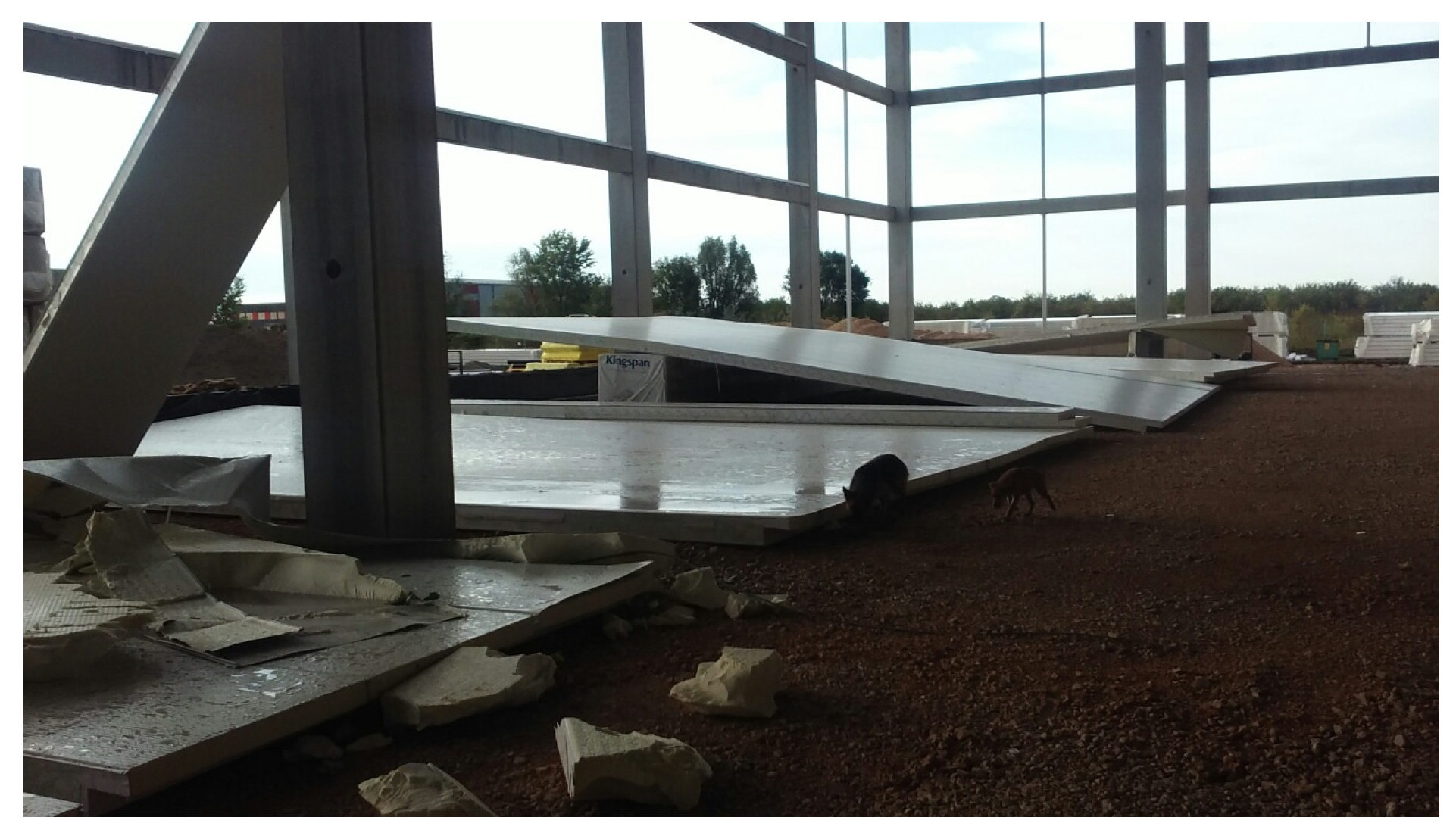
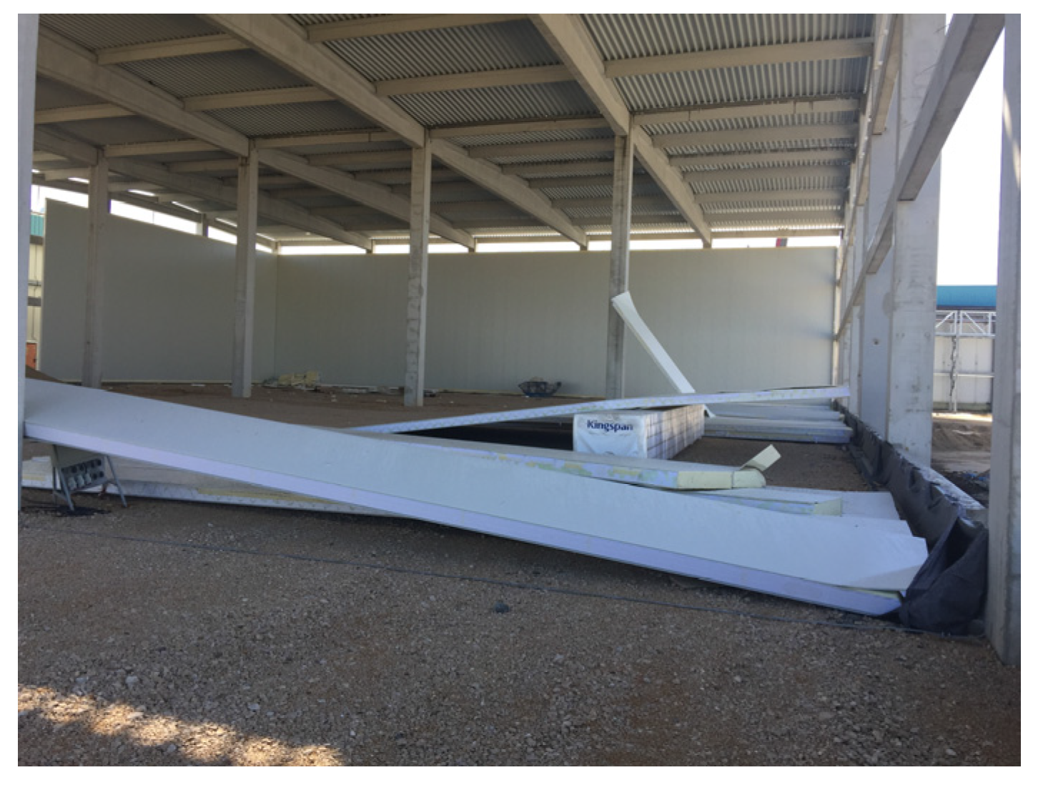
:1. Introduction
- -
- Sheet placement: two flat or slightly profiled galvanized sheets, usually with a thickness of 0.5 to 0.6 mm, are inserted into the machine, for example, PUMA-KROWN. The sheets are positioned horizontally and placed at a distance from each other that corresponds to the desired thickness of the panel.
- -
- Injection of PIR Foam: the polyisocyanurate (PIR) foam is injected between the two sheets. PIR foam is a type of rigid foam insulation known for its excellent thermal properties. The foam is injected as a liquid mixture, and it expands to fill the volume between the sheets. During this expansion, the foam adheres securely to the sheets.
- -
- Foam Expansion and Adhesion: as the PIR foam expands, it forms a strong bond with the sheets. The foam contains various components, including adhesion-promoting agents, that ensure a secure adhesion between the foam and the sheets. This adhesion is important to prevent fractures or separation at the junction between the sheet and the foam when the panel is subjected to tensile stress. Therefore, during tensile stress, the fracture does not occur at the junction of the sheet and the PIR but within the structure itself, as the experiments we performed showed.
- -
- Cooling: After the foam injection, the panels are allowed to cool down. The cooling process allows the foam to harden and set, ensuring structural integrity.
- -
- Cutting and Processing: Once the foam has cooled and hardened, the sandwich panels are cut into the desired dimensions. The sides of the panels may also be processed or trimmed as needed to achieve the desired finish or fit.
- -
- Finishing: The outer surfaces of the panels, typically the sheet surfaces, can be plasticized or coated with a layer of plastic material. This plasticization process serves to enhance the panel’s appearance and protect it from environmental factors. The color of the plasticized surface is customized according to the customer’s requirements.
- -
- Storage: Finally, the finished sandwich panels are stored before they are shipped or used in various applications such as construction, insulation, or industrial purposes.
2. Materials and Methods
2.1. Experimental Test Arrangement
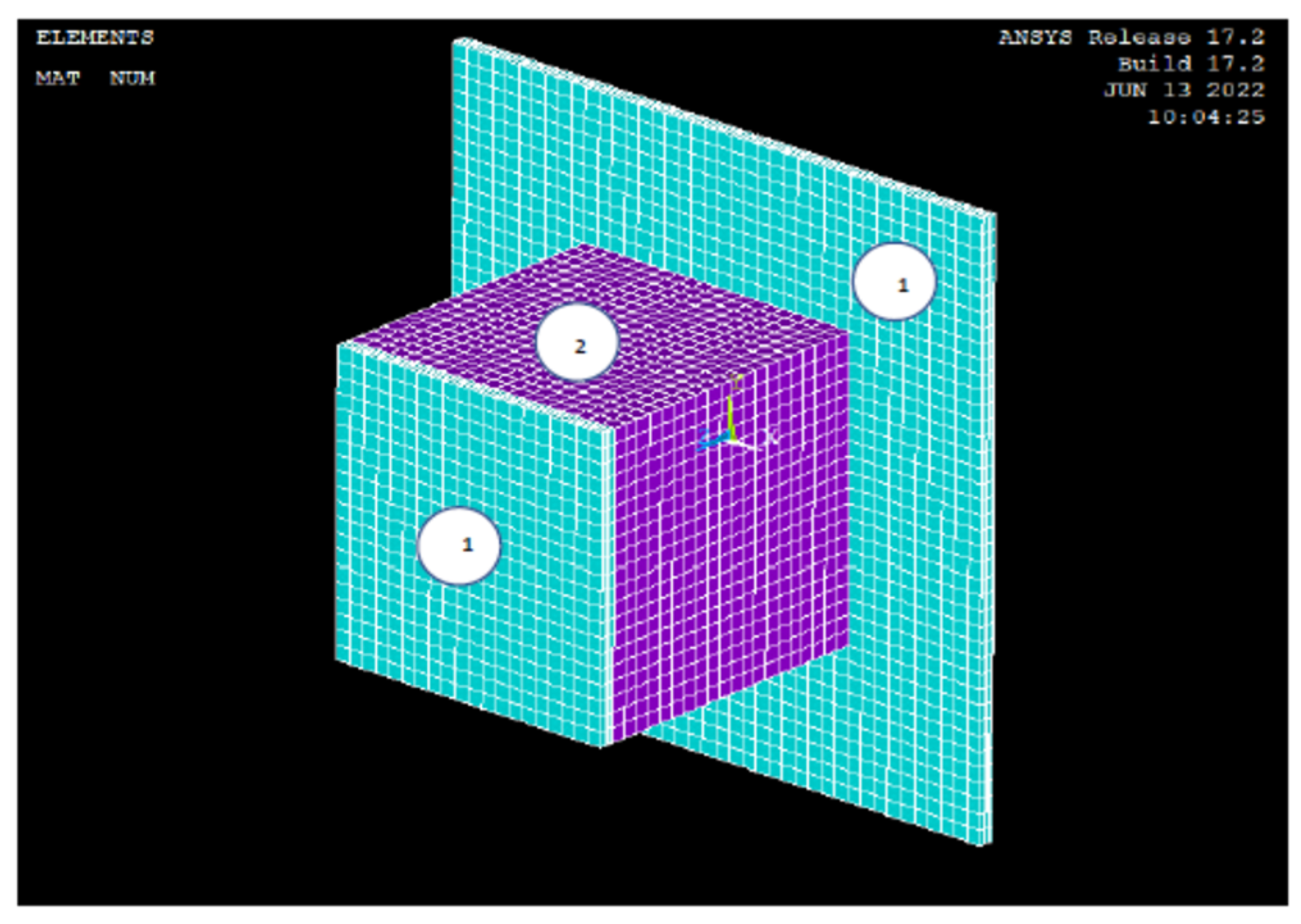
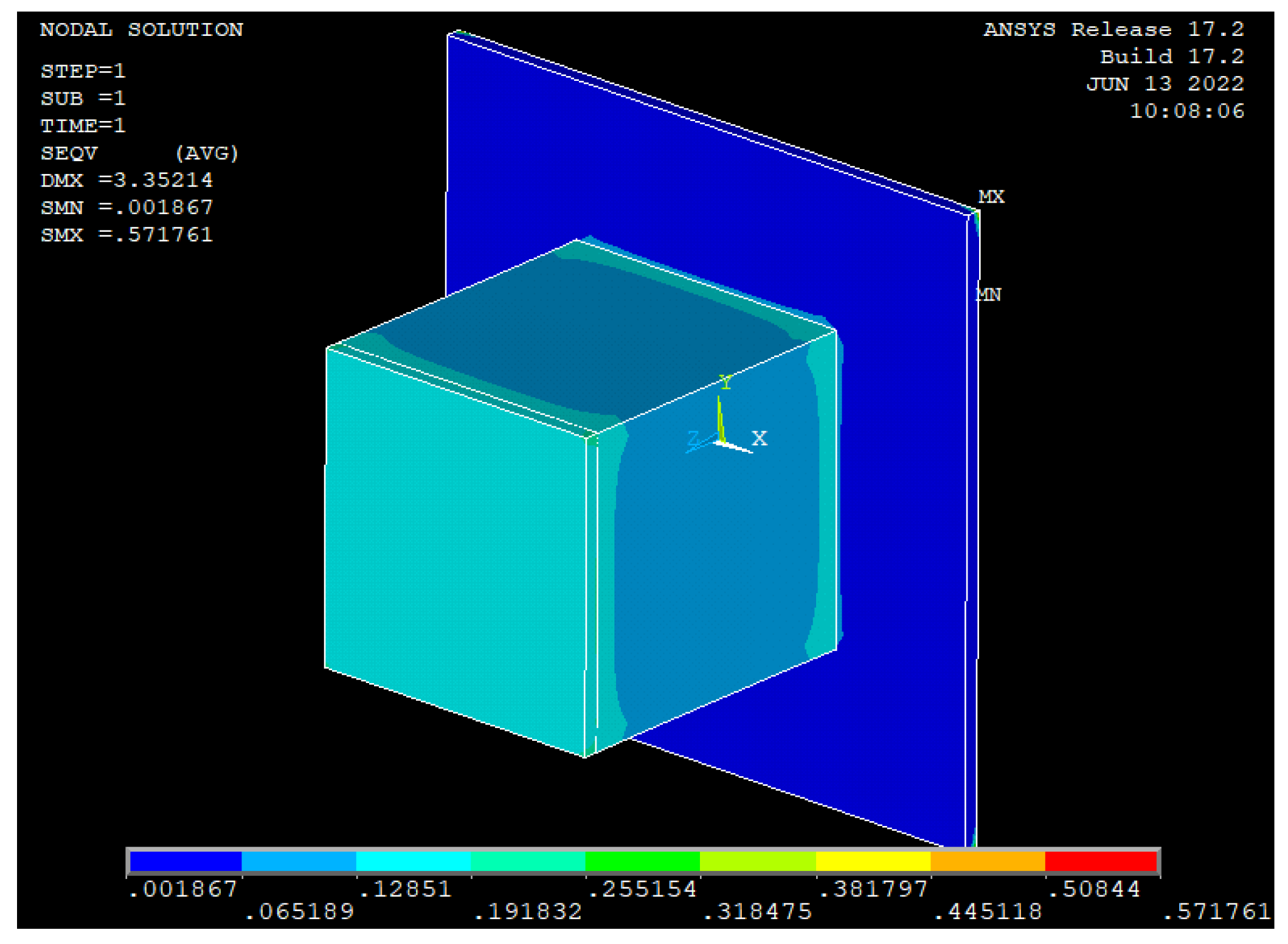
2.2. Finite Element Modeling
3. Results
3.1. Tensile Test
Comparisons Computation with Experimental Results
3.2. Compression Test
4. Conclusions
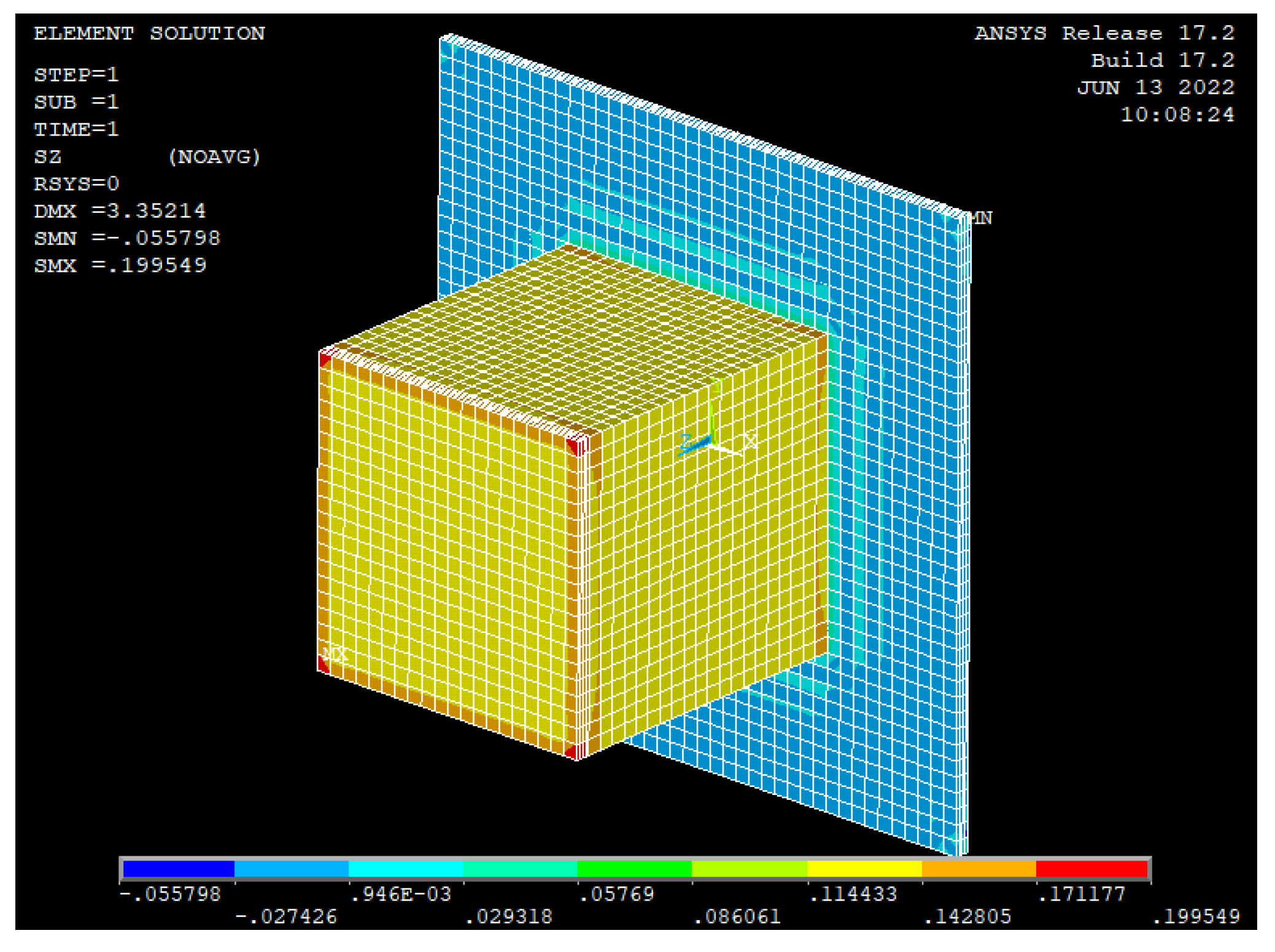
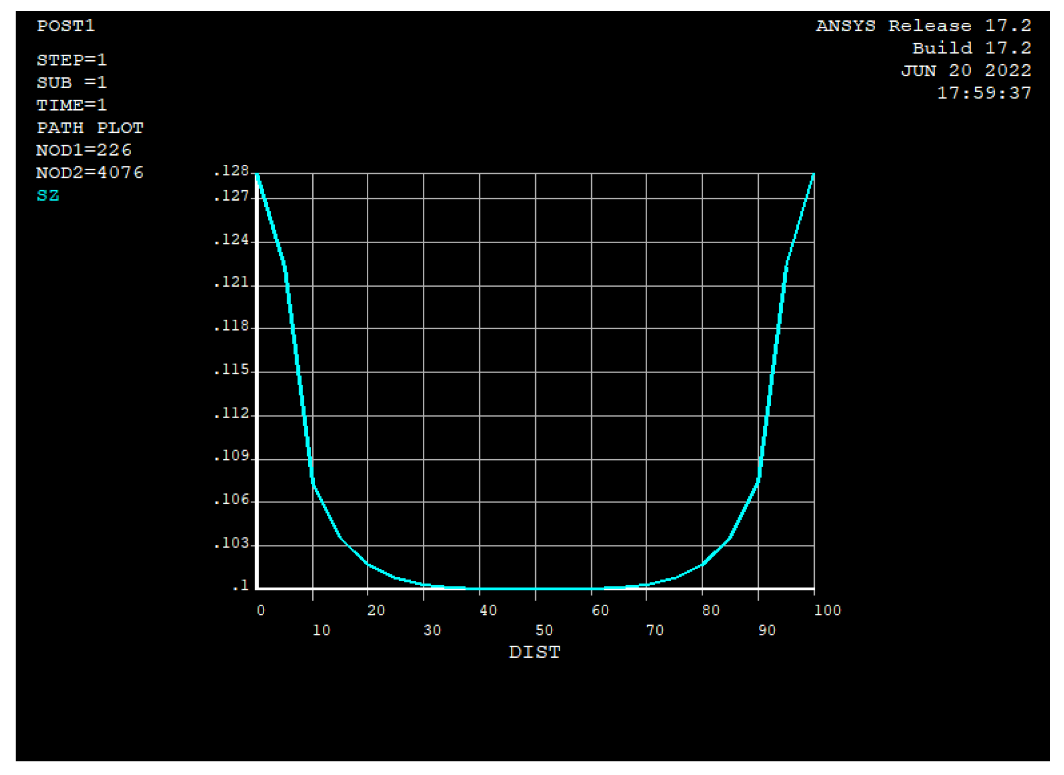
- The foam-based composite structure exhibited brittle behavior in the tensile test, with failure occurring in the core rather than at the core–face interface. The maximum tensile strength and tensile modulus for the core were 0.1175 and 3.264 MPa, respectively.
- Compressive force–displacement curves (Figure 15) revealed three distinct areas: linear-elastic, plateau, and densification. The compression strength and modulus were 0.8136 MPa and 1.035 MPa, respectively.
- These mechanical properties can be used in the design calculations of sandwich panels for various loads.
Author Contributions
Funding
Data Availability Statement
Conflicts of Interest
References
- Allen, H.G. Analysis and Design of Structural Sandwich Construction; Pergamon Press: Oxford, UK, 1969. [Google Scholar]
- Davis, J.M. Lightweight Sandwich Construction; Blackwell Science: Oxford, UK, 2001. [Google Scholar]
- Lee, H.; Park, H. Study on Structural Design and Manufacturing of Sandwich Composite Floor for Automotive Structure. Materials 2021, 14, 1732. [Google Scholar] [CrossRef] [PubMed]
- Zaharia, S.M.; Pop, M.A.; Udroiu, R. Reliability and Lifetime Assessment of Glider Wing’s Composite Spar through Accelerated Fatique Life Testing. Matarials 2020, 13, 2310. [Google Scholar] [CrossRef] [PubMed]
- Corigliano, P.; Palomba, G.; Crupi, V.; Garbatov, Y. Stress-Strain Assessment of Honeycomb Sandwich Panel Subjected to Uniaxial Compressive Load. J. Mar. Sci. Eng. 2023, 11, 365. [Google Scholar] [CrossRef]
- Studzinski, R.; Pozorski, Z.; Garstecki, A. Structural behavior of sandwich panels with asymesrical boundary conditions. J. Constr. Steel Res. 2014, 104, 227–234. [Google Scholar] [CrossRef]
- Mofrad, A.S.; Shlychkova, D.; Ciupack, Y.; Pasternak, H. Evaluating bending stiffness and resistance of sandwich panels at elevated temperatures. In Proceedings of the 13th International Conference Modern Building Materials, Structures and Techniques, Vilnius, Lithuania, 16–17 May 2019; pp. 465–469. [Google Scholar]
- Mofrad, A.S.; Pasternak, H. Behaviour of mineral wool sandwich panels under bending load at room and elevated temperatures. Eng. Struct. Technol. 2020, 12, 25–31. [Google Scholar]
- Davies, J.M. European Recommendations for Sandwich Panels, Part I: Design. In CIB Report Publication 257; International Council for Researching and Innovation in Building and Construction: Rotterdam, The Netherlands, 2000. [Google Scholar]
- Budescu, M.; Taranu, N.; Ciongradi, I.; Isopescu, D.; Vladoiu, C. Structural Behaviour of sandwich panels with profiled metallic facings and rigid polyurethane foam core. Compos. Struct. 2004, 1, 24–33. [Google Scholar]
- Valean, C.; Sosdean, C.; Marsavina, L.; Linul, E. Mechanical characterization of lightweight foam-based sandwich panels. Materials Today Proc. 2021, 45, 4166–4170. [Google Scholar] [CrossRef]
- Maksimović, K.; Maksimović, M.; Vasović Maksimović, I.; Rašuo, B.; Maksimović, S. Postbuckling and Failure Analysis of Layered Composite Panels. FME Trans. 2020, 48, 447–453. [Google Scholar] [CrossRef]
- Besant, T.; Davis, G.A.O.; Hitchings, D. Finite element modeling of low velocity impact of composite sandwich panels. Compos. Part A Appl. Sci. Manuf. 2001, 32, 1189–1196. [Google Scholar] [CrossRef]
- Kingspan KS1150 TF/NF. Available online: https://www.kingspan.com (accessed on 6 June 2023).
- EN 14509:2013; Self-Supporting Double Skin Metal Faced Insulating Panels—Factory Made Products—Specifications. European Committee for Standardization (CEN): Brussels, Belgium, 2013.
- Ansys Fluent software code—Release 17.2 Theoretical manuals. Available online: https://ansys.com (accessed on 6 June 2023).
- EJOT General Catalogue Building Fasteners, Fastening Technology for Expert Applications at the Construction Site. Available online: https://www.ejot.com/kataloge (accessed on 6 June 2023).
- EN 1993-1-4; Eurocode 3: Design of Steel Structures—Part 1–4: General Rules—Supplementary Rules for Stainless Steels. European Committee for Standardization (CEN): Brussels, Belgium, 2006.
- EN 1991-1-4; Eurocode 1: Action Structures—Part 1–4: General Actions—Wind Actions. European Committee for Standardization (CEN): Brussels, Belgium, 2005.


| Layers | γ [kg/m3] | E [N/mm2] | ν | fu [N/mm2] |
|---|---|---|---|---|
| Steel sheets | 7850 | 210,000 | 0.3 | 360 |
| Glue | - | 1600 | - | 30 |
| Steel facings PIR core | 7850 40 | 210,000 5.7 | 0.3 0.05 | 390 - |
| Item | Max F [kN] | Max δ [mm] | Type of Failure | FEM Max F [kN] | FEM Max δ [mm] |
|---|---|---|---|---|---|
| 1 | 0.527 | 3.45 | PIR core | 1.279 | 3.35 |
| 2 | 0.737 | 3.46 | PIR core | ||
| 3 | 1.143 | 3.20 | PIR core | ||
| 4 | 1.070 | 3.40 | PIR core | ||
| 5 | 1.159 | 3.20 | PIR core | ||
| 6 | 1.175 | 3.60 | PIR core | ||
| 7 | 0.705 | 2.60 | PIR core | ||
| 8 | 1.164 | 3.20 | PIR core | ||
| 9 | 0.500 | 5.00 | PIR core |
| Max F [kN] | Max δ [mm] | FEM Max F [kN] | FEM Max δ [mm] | |
|---|---|---|---|---|
| average | 1.09 | 3.40 | 1.279 | 3.35 |
| deviation | 0.70 | 1.91 | ||
| variation | 64.06 | 56.18 |
| Item | F [kN] | t [s] | δ1 [mm] | d1 [mm] |
|---|---|---|---|---|
| 1 | 19.810 | 141.9 | 86.98 | 56 |
| 2 | 8.136 | 144.8 | 78.63 | 61 |
| 3 | 7.966 | 195.6 | 80.32 | 56 |
| 4 | 7.060 | 113.6 | 75.39 | 60 |
Disclaimer/Publisher’s Note: The statements, opinions and data contained in all publications are solely those of the individual author(s) and contributor(s) and not of MDPI and/or the editor(s). MDPI and/or the editor(s) disclaim responsibility for any injury to people or property resulting from any ideas, methods, instructions or products referred to in the content. |
© 2023 by the authors. Licensee MDPI, Basel, Switzerland. This article is an open access article distributed under the terms and conditions of the Creative Commons Attribution (CC BY) license (https://creativecommons.org/licenses/by/4.0/).
Share and Cite
Stanisavljević, G.; Golubović Matić, D.; Komnenović, M.; Vasović Maksimović, I.; Flajs, Ž. Numerical and Experimental Study on Loading Behavior of Facade Sandwich Panels. Buildings 2023, 13, 1554. https://doi.org/10.3390/buildings13061554
Stanisavljević G, Golubović Matić D, Komnenović M, Vasović Maksimović I, Flajs Ž. Numerical and Experimental Study on Loading Behavior of Facade Sandwich Panels. Buildings. 2023; 13(6):1554. https://doi.org/10.3390/buildings13061554
Chicago/Turabian StyleStanisavljević, Gorjana, Darinka Golubović Matić, Milorad Komnenović, Ivana Vasović Maksimović, and Željko Flajs. 2023. "Numerical and Experimental Study on Loading Behavior of Facade Sandwich Panels" Buildings 13, no. 6: 1554. https://doi.org/10.3390/buildings13061554