Article

Nonlinear Dynamic Assessment of a Steel Frame Structure Subjected to Truck Collision

by
Fatemeh Safari Honar
1,
Vahid Broujerdian
1,
Esmaeil Mohammadi Dehcheshmeh
1 and
Chiara Bedon
2,*
1
School of Civil Engineering, Iran University of Science and Technology, Tehran 16846-13114, Iran
2
Department of Engineering and Architecture, University of Trieste, 34127 Trieste, Italy
*
Author to whom correspondence should be addressed.
Buildings 2023, 13(6), 1545; https://doi.org/10.3390/buildings13061545
Submission received: 25 April 2023 / Revised: 2 June 2023 / Accepted: 16 June 2023 / Published: 17 June 2023
(This article belongs to the Special Issue Progressive Collapse of Structures)

Abstract

:
The progressive collapse of structures subjected to a truck collision with ground floor columns is numerically investigated in this paper. For this purpose, a four-story steel building with a dual system (including an intermediate steel moment frame, with a special concentric steel bracing system in the longitudinal (x) direction, and an intermediate steel moment frame in the transversal (y) direction) is considered. The structure, which was designed according to AISC, ASCE7 and 2800 Iranian seismic standard guidelines, is located in seismic-prone area and subjected to eight different truck collision scenarios. The nonlinear dynamic analyses carried out in ABAQUS on a three-dimensional finite element (FE) numerical model include variations in collision features (i.e., mass and speed of the truck, the height of collision point), and are used to support the analysis of expected damage. The presented results confirm that increasing the truck mass and speed increases damage entity for the column and structure. Several influencing parameters are involved in damage location and progressive evolution. The height of the collision point from the ground also significantly affects the magnitude of structural damage, especially in terms of stress peaks in the panel zones for the target column. Finally, the perimeter columns are more vulnerable to impact than corner columns, in structures with dual system as with the examined four-story building. The presence of a bracing system parallel to the impacting vehicle can in fact reduce the deformation—and thus the expected damage—of the adjacent target column. Most importantly, it is shown that the numerically reproduced collision scenarios (and the associated damage configurations) based on truck impact are significantly more severe than those artificially created based on the conventional column removal method (i.e., alternate path (AP) analysis approach), which confirms the importance of more sophisticated numerical calculation procedures to investigate and assess the progressive collapse of structures.

1. Introduction

Progressive collapse is defined as the spread of initial local failure (from element to element), which can eventually result in the collapse of an entire structure or its disproportionately large part [1]. When a structural load-bearing member fails, the sustained load is notoriously transferred to adjacent members through an alternate path. Internal energy release due to the removal or damage of a structural member may consequently result in higher dynamic forces for adjacent structural components.
In 1968, a gas leak in the 22-story Ronan Point tower building in London (UK) caused the progressive collapse of the structure. Following this tragic event, many researchers started to focus on the issue of progressive collapse in buildings, and structural building codes registered major re-evaluation and modification, to efficiently support design [2]. The Ronan Point, from a literature point of view, is only one of various (and notorious) progressive collapse events. In 1973, for example, a progressive collapse occurred in the 26-story Skyline Plaza commercial building in Virginia (US) and was caused by form-work failure during a concreting [3]. Other examples of progressive collapse over the past few decades and resulting from many causes—such as terrorist attacks—included the 1995 bombing of the Murrah Federal Building in Oklahoma City—US (blast loading), the Khobar Towers in Saudi Arabia in 1996 (blast loading), and the demolition of the World Trade Center in New York—US in 2001. In this regard, design codes and specific guidelines have been prepared to support optimal structural design. Most available standards for structural design use some degree of strength and ductility for a given structural system, to withstand severe loads and prevent progressive collapse [4]. Progressive collapse, today, can be thus recognized among the most relevant topics for structural engineering. As such, a number of scholarly resources have been elaborated, including a collection of comprehensive review papers [5,6,7,8].
Among others, one of the factors that lead to the failure or reduction in structural strength was represented by the collision (for example from a vehicle) with a target load-bearing member. Vehicle-into-building accidents are quite common. These incidents typically occur when a driver enters or leaves a parking space perpendicular to a building. Based on the various literature data, it can be proven that (on average) there are at least five reported vehicle-into-building accidents every day, in the United States, and these accidents could have severe consequences, up to structural collapse. In this regard, the issue of truck collision with structural columns has been the subject of research by several researchers, including Ferrer et al. [9], Al-Thairy and Wang [10], Cao et al. [11], Auyeung et al. [12], Safari Honar et al. [13], and Siadati et al. [14]. Methods and approaches for studying the behaviour and failure of these members under impact have been developed and addressed over the years. In most cases, simplified assumptions are taken into account, in place of refined and expensive collision analyses.
From a research perspective, multiple efforts have been spent to address the progressive collapse mechanisms of various structural typologies. Numerical investigations have been presented in [15,16,17,18,19] to study the progressive collapse of steel structures under the sudden column removal scenario, based on three-dimensional FE models. Tsitos et al. [20] examined the typical processes of progressive collapse in terms of nonlinear or linear and dynamic or quasi-static analyses, by using a combination of dead and live loads. Their results proved that linear analyses are commonly highly non-conservative for safety purposes. The progressive collapse in structures is a challenging task also because it can be influenced by several parameters. Kordbagh and Mohammadi [21] examined the impact of panel zone on the progressive collapse and resistance of steel structures. Their findings indicate that the inclusion of the panel zone in structures with I-section columns can exacerbate the progressive collapse phenomenon. Additionally, both the number of floors and the span length of target buildings represent key parameters with relevant effects on the resistance of structures against progressive collapse [22].
In terms of possible mitigation, numerous studies [23,24,25,26,27,28] have been elaborated to examine the possible benefit of bracing systems against the progressive collapse of buildings. These investigations consistently demonstrated that the incorporation of braces can effectively reduce the dynamic response of a target structure, thereby decreasing its susceptibility and vulnerability to progressive collapse as a consequence of column removal and impact energy release. However, it is also important to note that in most of these studies, the assessment of bracing efficiency on progressive collapse has been preliminary conducted based on the simplified column removal approach only.
The performance of steel structures with moment frames under impact loading has been analysed by few researchers [29,30,31]. The results from nonlinear dynamic analyses show that the effect of impact waves on a given target structure is much greater compared to equivalent quasi-static loads. The energy transferred to the target structure causes severe nonlinear mechanisms in the building response, and progressive damage evolution. To simulate the behaviour of a target structure under impact or vehicle collision, more refined nonlinear dynamic simulations (both in terms of structural description and impact loading definition) are thus needed. However, while there is evidence of this need, the existing codes and guidelines for design still allow the use of simplified, equivalent quasi-static analyses, with obvious consequences in terms of design detailing and performance assessment. Also, the cited studies are focused on targeting steel structures with moment frames only. In this sense, there is a gap in the context of vehicle collision research when structures characterized by a dual system (i.e., consisting of both moment frames and bracings) are taken into account.
In studies on progressive collapse, robustness and redundancy are primary aspects of structural capacity assessment [32,33]. The intrinsic features and corresponding structural behaviours due to different causes of destruction, such as from vehicle collisions or explosions, are often marginally addressed, and most of the attention is focused on damage mechanisms and progressive collapse analysis for the examined structures, even under a rather simplified/conventional impact description [34,35]. On the other side, it is generally recognized that, among others, one of the possible causes of progressive collapse in buildings can take the form of the vehicle collision with building members, and this is strongly different from other extreme loading configurations (both in terms of loading features and corresponding structural behaviours).
In the present investigation, the progressive collapse of a multi-story steel frame is investigated by simulating the collision of a truck with its ground-floor columns. The particularity of the selected steel building is that the lateral load-resisting components take the form of a dual system, which consists of a moderate steel moment frame, with a special concentric steel brace in the longitudinal (x) direction and a moderate steel moment frame in the transversal (y) direction. The effect of bracings on the progressive collapse, as well as the effect of impact features, are thus numerically investigated in terms of observed structural damage and consequent failure. For this purpose, different scenarios of possible truck collision with a selection of steel columns are simulated with the support of nonlinear dynamic analyses. The reference FE numerical model takes the form of a three-dimensional building assembly, in which both nonlinearities of materials and geometry are considered. In addition, different collision parameters, such as the speed v and mass M of the truck, the position of the collision point (i.e., the position of target column) and its height H (from the ground) are investigated. Finally, the impact-induced stresses in the brace members and in the panel zones of target columns are numerically evaluated and addressed, especially towards simplest estimates based on sudden column removal (as it is for the alternate path (AP) analysis approach [36]).

2. Numerical Investigation
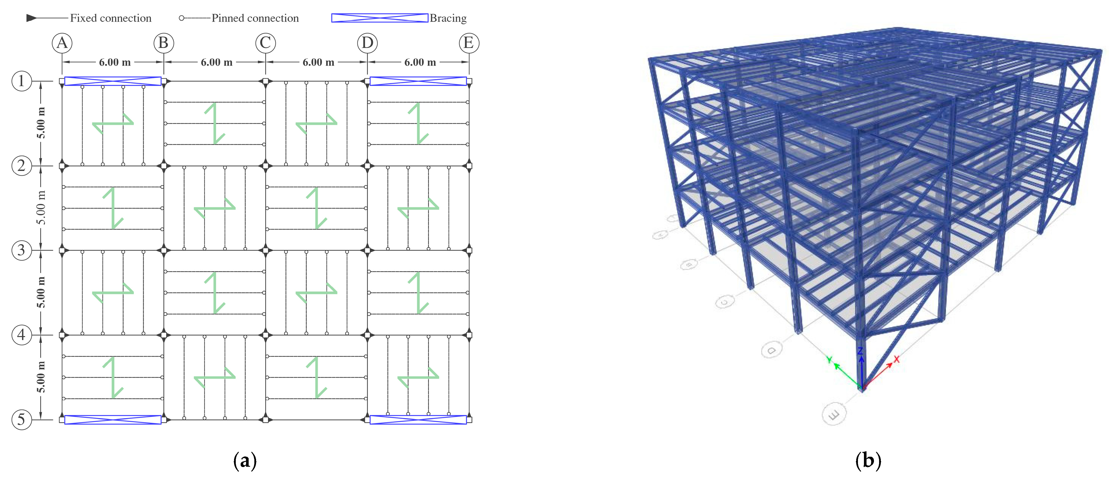
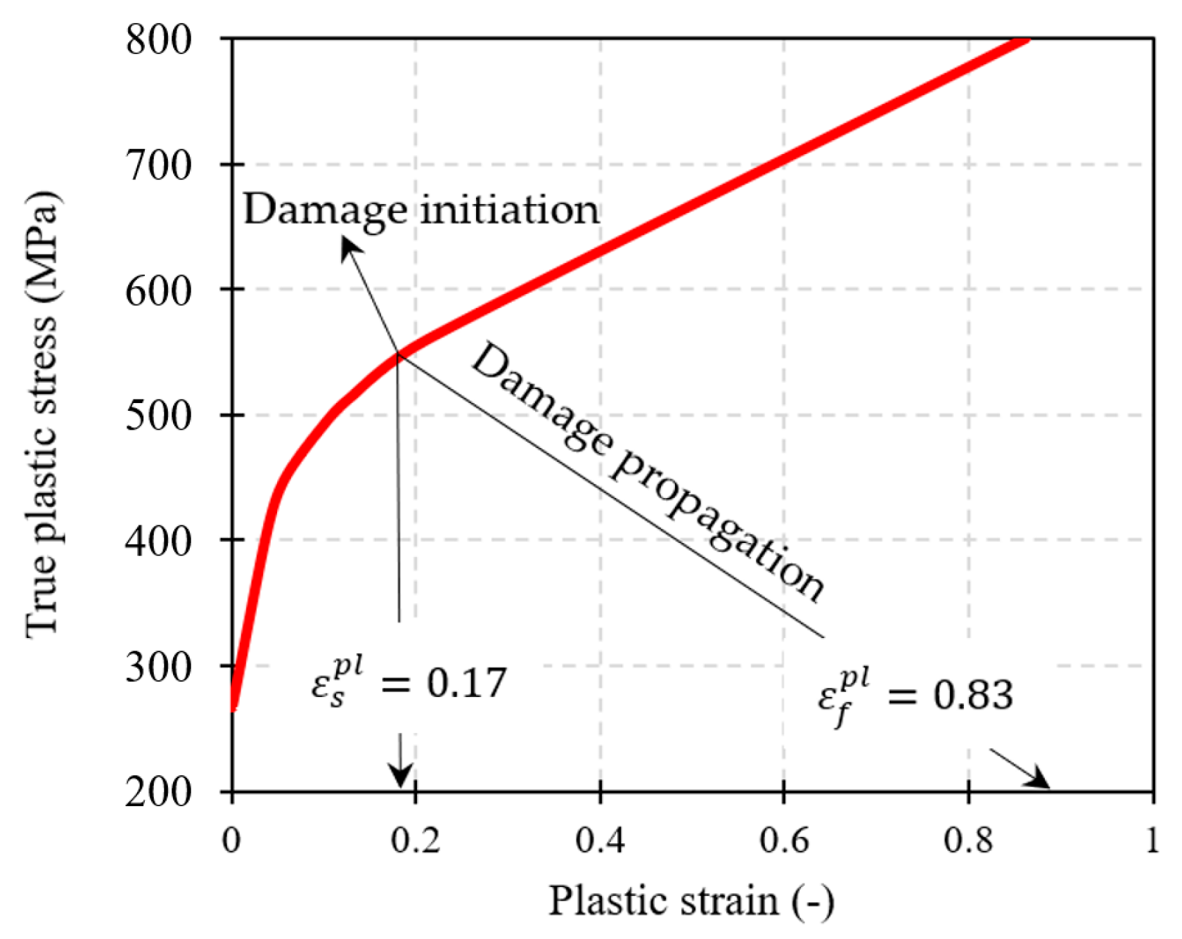
The reference multi-story steel structure is located in a seismic-prone area (Tehran, Iran). It was first designed in ETABS software [37] according to existing seismic codes (ASCE [1], AISC [4] and 2800 Iranian seismic standards [38]). Successively, the multipurpose ABAQUS software v.6.14 [39] was validated towards the results of previous research efforts (Section 3.2). In a subsequent step, the sections of beams, columns and braces obtained from ETABS were modelled in ABAQUS to investigate the progressive collapse of the selected building under different impact configurations.

2.1. Modelling

A 4-story frame building with uniform floor plans was considered. The span lengths in x and y directions were set at 6 m and 5 m, respectively (Figure 1). The height of the floor was set at 3.2 m and the roof of the structure was assumed as composite. The lateral resisting system in x direction consisted of a dual system, composed of the moderate steel moment frame and special concentric steel bracing, while in the y direction a moderate steel moment frame was used. Figure 1a shows the plan and the three-dimensional view of the building. For the seismic design, the peak earthquake acceleration was set at 0.35 (Tehran region). The soil category (type C) was selected in accordance with ASCE [1]. Dead and live loads on the floor partitions were set at 2.1 and 2 kN/m2, respectively. The super dead and live loads on the roof were set at 2.5 and 1.5 kN/m2. The dead load of the perimeter walls around the floors and the roof was assumed at 7 and 3.5 kN/m2, respectively. The design parameters of building components are also listed in Table 1.
For example, according to Table 1, C300X12 represents the column cross-section in the form of a hollow square, with the height and width of 300 mm and a plate thickness of 12 mm. The cross-section F300X12-W220X12 is associated with a beam in the form of the web (with dimensions of 300 mm× 12 mm in thickness) and flange (with dimensions of 12 mm × 220 mm). In the case of joist beams, IPE180 and IPE200 profiles were used for the cross-section of members with 5 m and 6 m span, respectively. Finally, for cross-sections of bracing members, double-channel profiles were used (2UNP120).
The steel material for structural members was numerically described as elastic–plastic, with a specific gravity of 7850 kg/m3, Poisson’s coefficient of 0.3, Young modulus of 200 GPa, yield stress of 331.2 MPa, ultimate stress of 805 MPa and failure strain of 0.2135.

2.2. Preliminary Validation of Numerical Simulations

The most important issues to verify for collapse analyses, as in the present study, are the impact/impactor features and the contact behaviour between the impactor (truck) and the structure (steel column). For this purpose, according to possible types of failures that can occur in a steel column, three steps/types of validation procedures were preliminary performed in the present study. The attention was, in fact, focused on the collapse of steel columns in terms of (i) global plastic buckling failure (Section 2.2.1), (ii) tensile tearing failure (Section 2.2.2) and (iii) shear failure (Section 2.2.3).

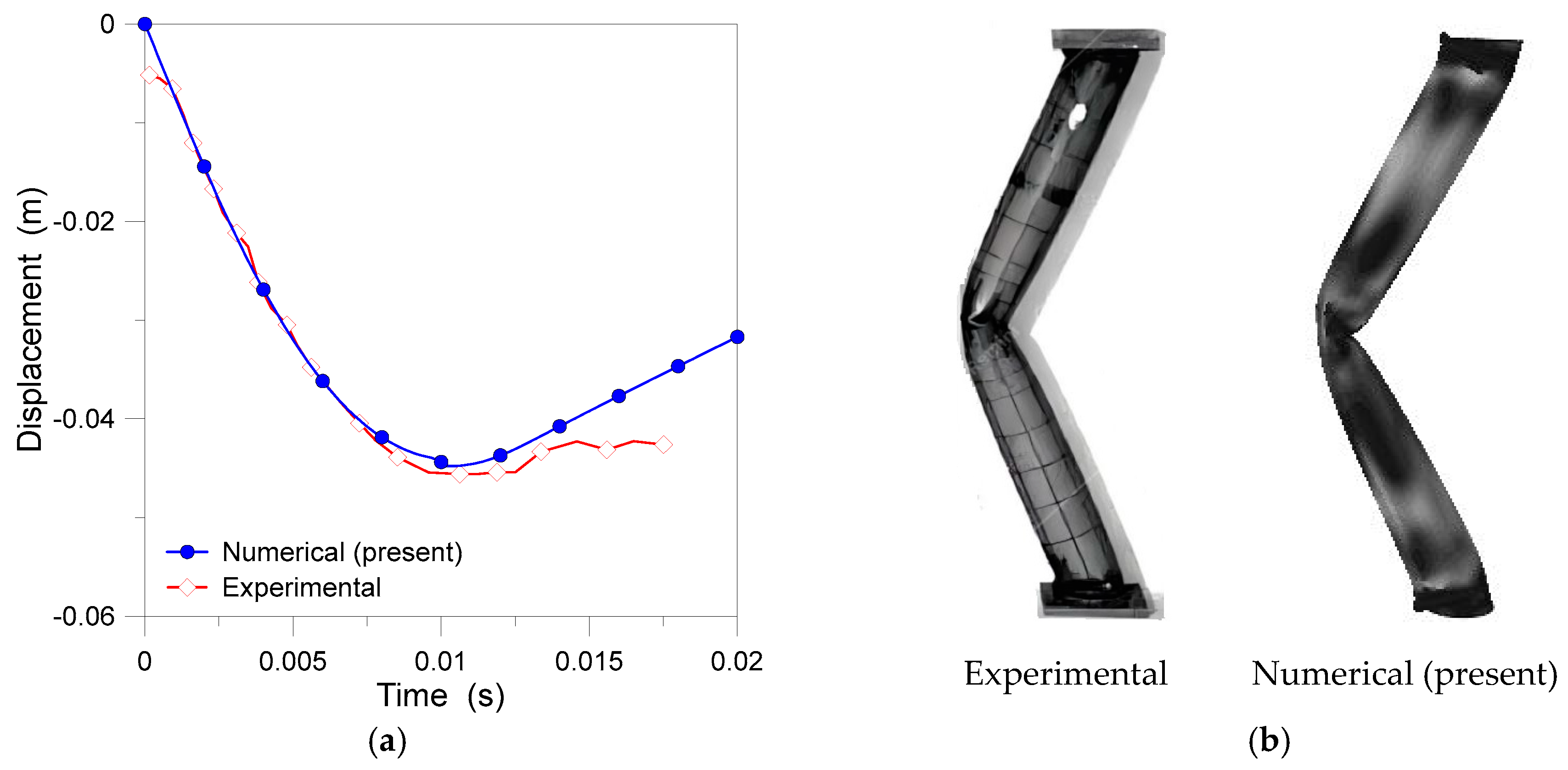
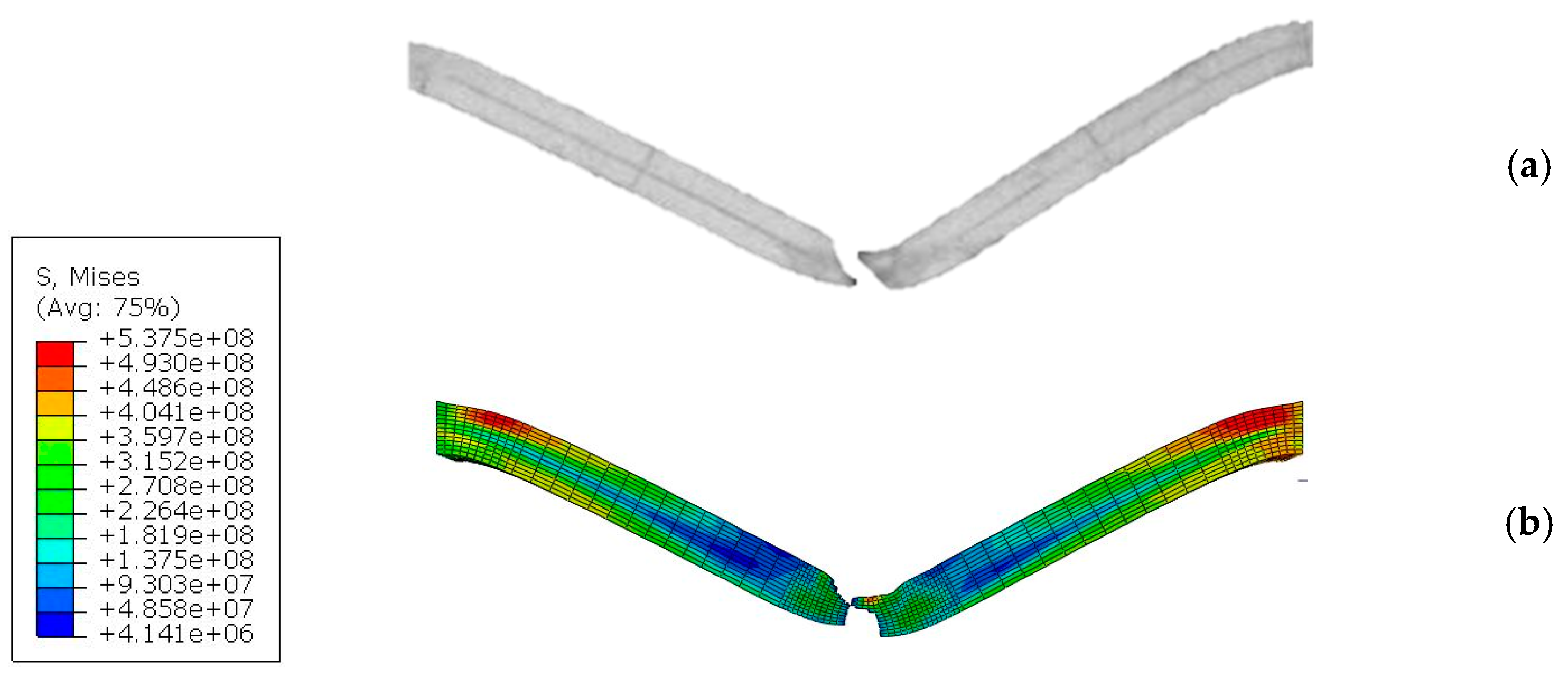
2.2.1. Global Plastic Buckling Failure

The simulation of type (i) failure was first validated using the experimental results reported in [40]. In those background experiments, a tube-shaped beam with a radius of 49 mm and a length of 1 m was examined. In the presently developed numerical model from ABAQUS, the beam was simulated using shell elements (Figure 2).
The considered material for the column was steel with Young’s modulus of 200 GPa, Poisson’s ratio of 0.3, yield stress of 500 MPa, and specific gravity of 7850 kg/m3. An impactor with dimensions of 160 mm × 100 mm × 40 mm was used, according to Figure 2. The impactor was characterized by Young’s modulus of 1000 GPa, Poisson’s ratio of 0.3 and specific gravity of 44,200 kg/m3. The impactor was chosen to behave as a rigid body, with an imposed collision speed of 7 m/s.
The numerical simulation revealed that the beam experienced significant global destruction and large deformations, as a result of the imposed lateral impact. The stability of the beam was severely compromised, thus leading to major structural deformations. The displacement–time curves obtained from the present numerical simulation and the reference experimental measurements from [40] are compared in Figure 3a. The close correlation between numerical and experimental plots, as shown, confirms the accuracy of the presently developed model in capturing the load-bearing member behaviour. Furthermore, Figure 3b demonstrates that the deformation of steel members (at failure) based on numerical analysis exhibits a rather good agreement with the reference experiment.

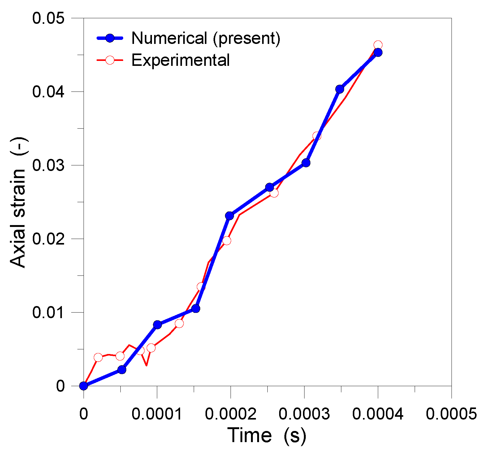
2.2.2. Tensile Tearing Failure

Tensile failure (type (ii) mechanism) is known to represent another important failure mode for steel columns. The validation for present numerical analyses was performed according to the experiments performed by Bambach et al. [41] and Al-Thairy and Wang [42]. The steel member was modelled in ABAQUS as a square hollow section and a cross-sectional zone of 16 mm × 500 mm, and a length of 700 mm. The beam was subjected to a M = 600 kg impactor at the imposed collision speed of v = 6.2 m/s.
Undeformable materials were considered because the end gusset plates and the impactor do not deform. The steel used in the present numerical model has a specific gravity of 7850 kg/m3, elastic-plastic behaviour with Young’s modulus of 200 GPa, a yield stress of 456 MPa and failure stress of 584.64 MPa, with true rupture strain of 0.145. The strain rate sensitivity of steel was calculated using the Cowper-Symonds equation in ABAQUS. To this aim, according to experimental results reported in [41], a value of 40.4 for D parameter and a value of 5 for N parameter were used.
Figure 4a–c show a comparison of deformed the shape based on (a) the reference experiment [41], (b) the reference numerical simulation [41], and (c) the present numerical analysis. Moreover, Figure 4d shows the ductile damage failure at the impact location in the reference research [41] and in the present numerical study. Also, in this case, it can be seen that comparative results exhibit a rather good resemblance, thus emphasizing the accuracy and reliability of the current numerical modelling strategy.

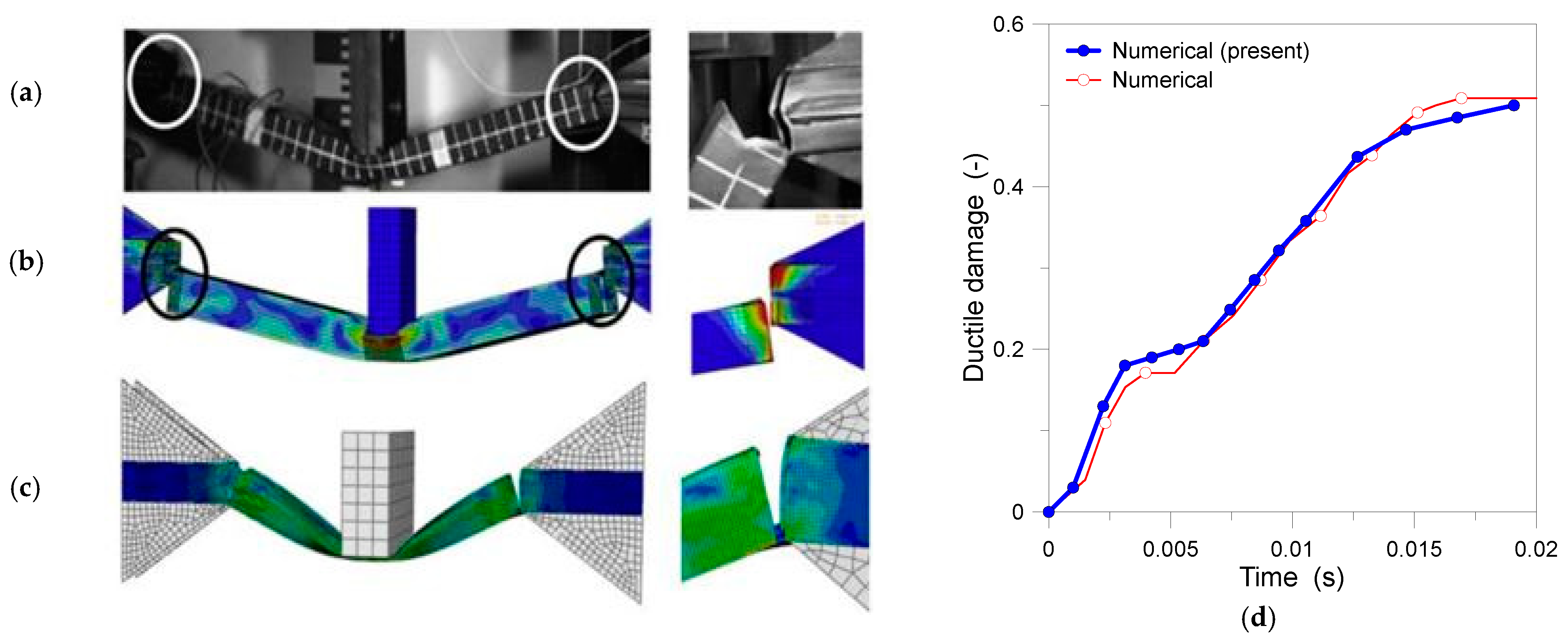
2.2.3. Shear Failure

The results of Yu and Jones [43] were also used in the validation of the type (iii) mechanism, which is shear failure. A mild steel beam with a solid rectangular cross-section, clamped ends and 101.6 mm in clear span was modelled. The ABAQUS brick element C3D8R was used to simulate both the target beam and the impactor. The beam was impacted transversely at a distance of 49.9 mm at an imposed velocity of 10.6 m/sec, by a rigid mass of 5 kg. The element size of 2.5 mm was selected for the mesh of the beam, while near the impact zone and the supports the element size was reduced to 0.5 and 1 mm, respectively, in order to achieve higher modelling accuracy. As in Section 2.2.2., strain rate effects were described by employing the Cowper–Symonds equation from the ABAQUS library, with material parameters D = 1.05 × 10⁷ s−1 and q = 8.3. Figure 5 shows the true stress–strain relationship of mild steel. Steel density, Young’s modulus and Poisson’s ratio were described for the previous simulations. Plastic strain at the onset of shear damage was set at 0.172, with the maximum shear stress ratio equal to 1.8, the maximum strain rate of 120 s−1, and the final plastic strain equal to 0.83, with the final plastic displacement of 0.000415 m as the shear failure constant.
In Figure 6, the deformed shape of the target steel beam after experiencing complete shear failure is proposed. There is a notable agreement between the two deformed shapes, both in terms of damage location and angle of the shear failure surface. Table 2 presents a comparison of the presently calculated maximum transverse displacement for the steel beam, towards the experimental results reported in [43] or the numerical results from [44].
Finally, Figure 7 provides a comparison of axial normal strain for the target steel beam beneath the impact point, as obtained from the present model and the experimental results reported in [43]. Also, in this case, the collected results exhibit a good agreement, and thus confirm that the developed numerical modelling strategy successfully captures the behaviour of the target member under shear failure.

3. Collision Analysis

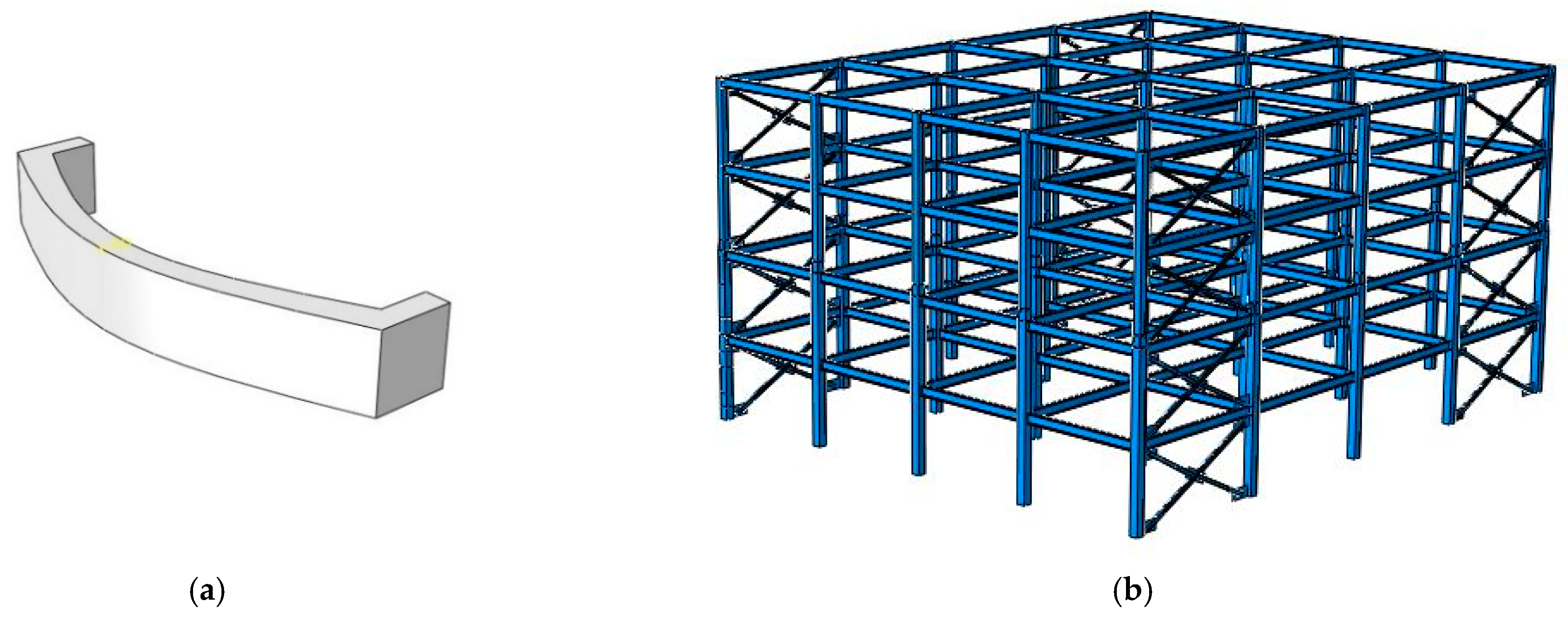
3.1. Specifications of Reference Model

The constituent element for beams, columns and braces composing the four-story building was defined as a fully three-dimensional, eight-node solid brick (C3D8R type) from the ABAQUS library [37]. The specifications of steel material were described in accordance with preliminary design assumptions [42]. In terms of tensile failure, the plastic strain at the onset of damage was set at 0.115, with a maximum tensile stress of 0.7 MPa, a maximum strain rate equal to 14.2 s−1, with the final plastic strain set at 0.145 and the final plastic displacement equal to 0.000291 m. Furthermore, in terms of shear failure, the plastic strain at the onset of damage was set at 0.295, with a maximum three-axial stress of 1.85 MPa, a maximum strain rate of 320 s−1, and a final plastic strain equal to 0.65, with a final plastic displacement of 0.000415 m. It is worth noting that the ductility of cold-formed materials can be taken into account based on [45]. A “tie” constraint was used to connect beams, columns and braces, and to simulate perfectly welded joints.
For truck modelling in ABAQUS, its bumper was only taken into account, and its constituent part was set as a discrete rigid type (Figure 8a). Vehicle deformation and energy absorption were conservatively disregarded. The modelled structure is shown in Figure 8b. Based on earlier validation (Section 2), a reference mesh size of 5 cm was used for columns, beams and braces. For the target column, a finer mesh was taken into account (1 cm), due to its higher sensitivity to impact loading and the consequent need for more accurate analysis of local phenomena.

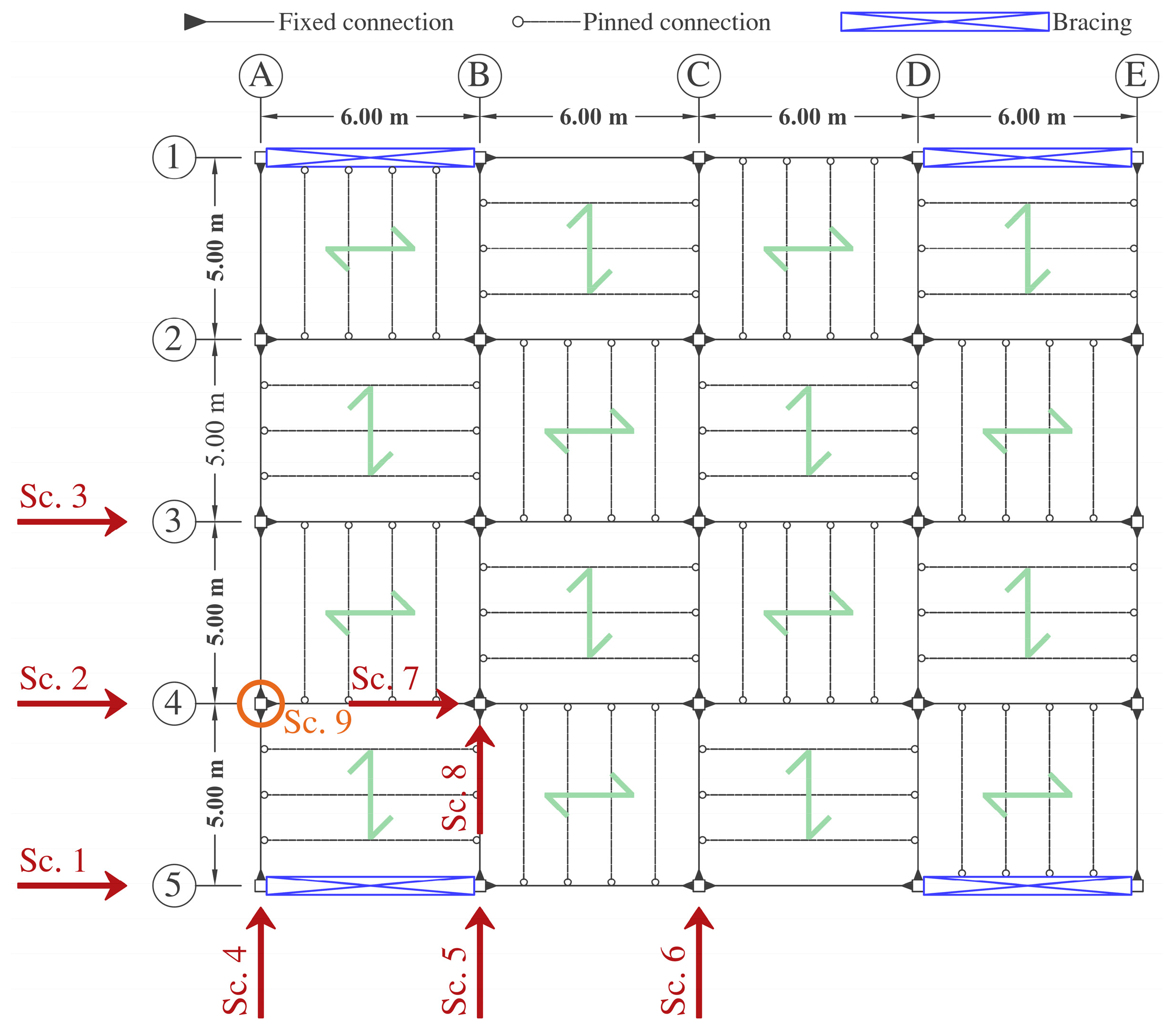
3.2. Impact Loading Scenarios

To investigate the effect of bracings contribution and the location of the target column within the examined three-dimensional structure, in terms of progressive collapse, a set of 8 collision scenarios (“Sc.”), including six configurations for target exterior columns (Sc. 1 to 6) and two configurations for target internal columns (Sc. 7 and Sc. 8), were considered. A schematic view is proposed in Figure 9, with evidence of bracing systems.
The selected Sc. 1 to Sc. 8 scenarios were designed to include a possible collision of the vehicle with corners, perimeter and internal columns, respectively, by taking into account several truck directions. More precisely, to qualitatively and quantitatively compare the structural response of moment frame and dual system configurations, collision scenarios were numerically described in both the x and y directions. The analyses were performed by varying further parameters of the impactor, such as its speed v, mass M and position (i.e., target column) or height from ground H, see Table 3. Finally, Sc. 9 in Figure 9 was introduced to represent an additional configuration, which was analysed for comparative purposes based on the simplified column removal method (AP approach).

3.3. Progressive Collapse Analysis

To prevent progressive collapse in buildings, among other things, the US Department of Defense (DoD) presented a guideline in support of the design. In more detail, the AP approach recommended in the UFC guidelines is a prescriptive method that allows a designer to incorporate structural strengthening to bridge over a removed element, thus adding robustness and redundancy throughout the structure [46].
To identify and measure the damage state for the examined structure under various collision scenarios, the four-level performance criteria for extreme loads, as specified in ASCE, were taken into account in the present study. The latter specifies the failure type and its classification in “light”, “moderate” or “severe” damage states, as summarized in Table 4 [29].

4. Results and Discussion

4.1. Parametric Study

The effect of vehicle mass M and speed v, as well as the collision height H, was initially investigated. Figure 10 illustrates the vertical displacement at the top of the target column, under selected scenarios. When the M is set either 4 t or 6 t, there is no significant difference in the measured vertical displacement (especially for Sc. 4). However, when the M increases to 8 t, a substantial effect can be noted on the structure, resulting in markedly larger displacement amplitudes. For Sc. 2, the maximum displacement with M = 8 t is approximately four times greater than the M = 6 t configuration, which is about two times larger than the M = 4 t setup. Additionally, the vertical displacement in Sc. 2 is significantly greater than in Sc. 4. The maximum displacement amplitude in Sc. 2 (with M = 8 t) is approximately ten times Sc. 4. All these observations suggest a positive impact of the bracing system on the performance of target columns.
As shown in Figure 11, the height H of the collision point also severely affects the vertical displacement of the target column. The predicted structural damage for Sc. 4, when H = 1 m, is much higher compared to other configurations. However, for Sc. 2, the displacement variation among various collision heights is negligible. It can be thus concluded that for target columns which are adjacent to the bracing system, the lower collision the point from the ground and the higher its possible effect on the column performance.
Finally, according to Figure 12, it is possible to note that there is no significant difference in increasing the impactor speed v from 10 m/s to 15 m/s, for the examined steel structure and collision configurations. However, when increasing v to 20 m/s, the amplitude of measured displacement is significantly larger. This finding basically confirms that, as expected, by increasing the impactor’s speed v, damage in the column and in the structure increases due to higher input impact energy. There are much more complex phenomena to account, for example, it can be seen that for Sc. 2 (with v = 20 m/s) there is a more pronounced deformation (and thus structural damage) than in other impact conditions, especially when compared for example to Sc. 4. In that case, at the early stage of vehicle collision, even changing v, the column behaviour is approximately constant. The dramatic increase in measured displacement (and consequent damage) occurs for v = 20 m/s, with clear evidence of sudden column failure.
Table 5 summarizes major failure observations from collision scenarios based on Sc. 2 and Sc. 4, at a time interval of 0.1 s after collision. It can be seen that the observed damage type for each target column is different, for all the examined combinations of mass M, velocity v, and collision height H. No damage was generally observed at the top of the target column (“N”), while tensile failure (“T”) occurred, in most cases, at the column base. Also, for all configurations in Sc. 4 (excluding the setup with H = 1 m), shear damage (“S”) was observed in the collision region, due to the presence of gusset plates at the top and bottom of target column, as well as the bracing system. This is not the case for Sc. 2, where major damage was observed at the bottom and top of the target column.

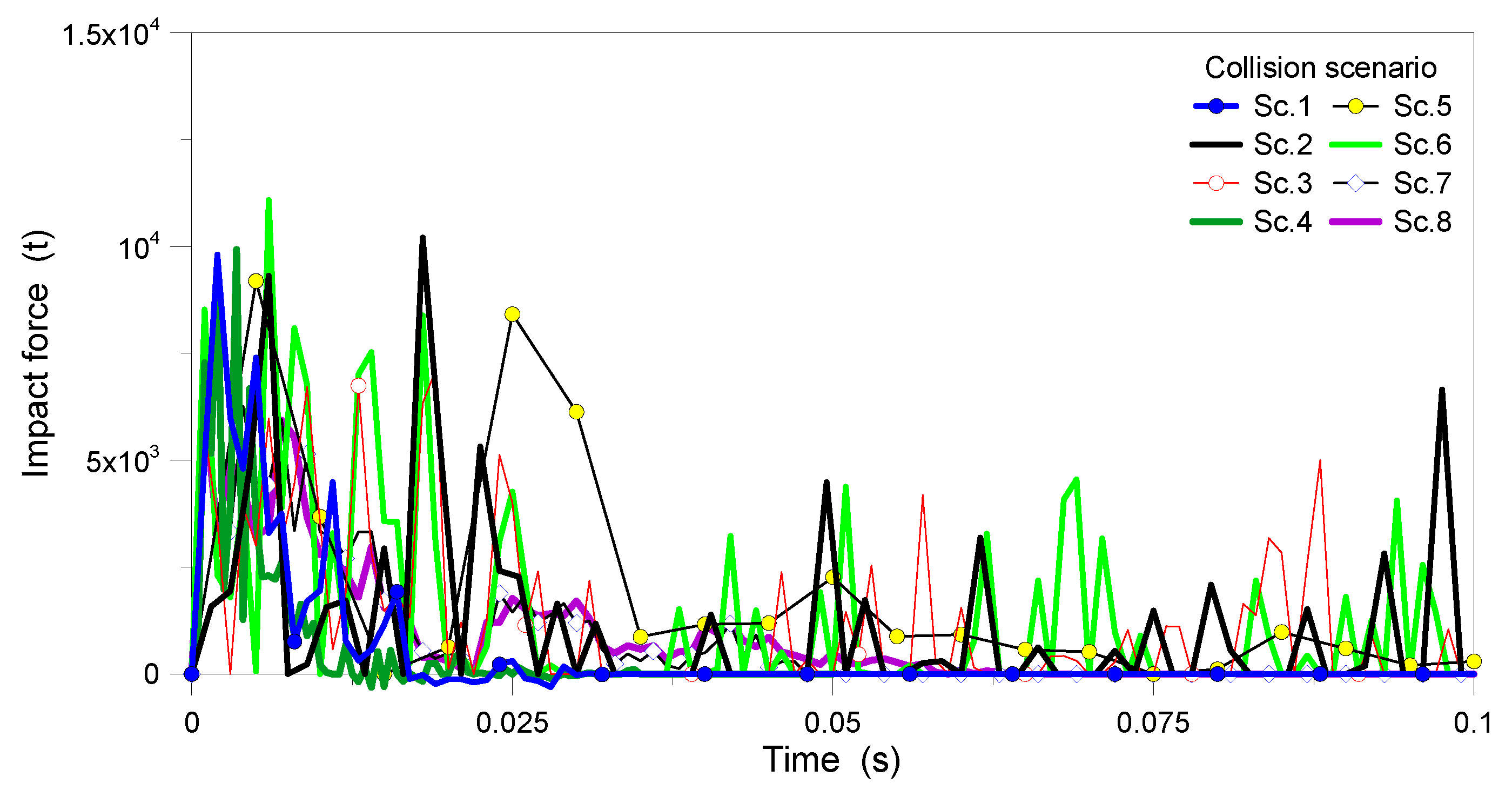
4.2. Failure Mode and Impact Force

Among the selected collision scenarios, the possible mitigating contribution of bracing systems was numerically addressed by considering different column positions under fixed impactor features. As an example, Figure 13 shows the parametric results for collision scenarios based on M = 8 t, v = 20 m/s and H = 1.25 m.
Based on Figure 13, it is possible to note that the stresses peak in the target columns and the connected beams were found typically larger than the reference yield stress (331.2 MPa), with evidence of plastic behaviour. Also, in the columns adjacent to braces, the stress in some elements near the impact region was observed to exceed the ultimate material stress (480 MPa). Finally, in other columns, the monitored stress peaks were found also to exceed the ultimate stress (especially at the beam-to-column connection), but with limited extension only. In support of Figure 13 evidence, Table 6 shows various observed failure modes for the selected collision scenarios.
According to Table 6, in more detail, it can be noted that the type of damage for the target column typically changes with the column positions. In the columns adjacent to braces, major damage was observed to occur at the collision region. Such a finding was mainly justified by the presence of gusset plates at the top and bottom of the target column, but also in the bracing system. For other target columns, conversely, most of the damage was observed at the top and bottom of the target member only. Additionally, for Sc. 7 and Sc. 8 configurations only, tensile failure was noted to occur at the top of the target column. While failure at the bottom of the column was observed for all target members, it can be concluded that this region is the most vulnerable to failure, regardless of the collision and impactor features.
From Table 6, it is also worth noting that the panel zone in Sc. 2, Sc. 3 and Sc. 6 configurations, which are not adjacent to the brace system, clearly enters the plastic zone. This is not the case of the other scenarios, where it remains elastic, as the consequence of the positive effect of braces on the overall performance of the structure and especially of panel zone.
Figure 14 shows a comparison of vertical displacement monitored at the top of the target column, for the same collision scenarios. As it can be seen, the difference between displacements in Sc. 2, Sc. 3, Sc. 5 and Sc. 6 is rather negligible. However, a partially larger vertical displacement can be noted for Sc. 6. This finding suggests again that target columns that are adjacent to the braces have improved performance against impact load, which confirms the positive effect of the bracing system itself. Additionally, based on Figure 14a, the performance of the target column in terms of vertical displacement in Sc. 1 (i.e., along the bracing system and moment frame) looks more stable than in Sc. 4 (i.e., which is aligned with moment frame only).
For completeness, Figure 15 provides further insight into the vulnerability of different target columns, depending on their position within the structure, in terms of measured impact force. In more detail, from both Figure 14 and Figure 15, it can be seen that the perimeter columns are more susceptible to failure, compared to corner columns. Such a disparity can be attributed to the fact that a portion of the impact energy is absorbed by gusset plates and braces, which are typically present in corner spans. In multi-story structures with a dual system, where the braces are positioned in corners, it can be thus inferred that the perimeter columns are associated with a higher failure risk compared to the corner columns. This outcome is in contrast with previous studies which have highlighted, for steel structures with moment frames, the higher vulnerability of corner columns over perimeter columns.
In the case of Sc. 7 and Sc. 8 configurations, which represent collisions with internal columns, it is possible to see that the vertical displacement at the top of the target column is significantly more pronounced, compared to perimeter and corner columns. This observation is clearly emphasized in Figure 14c, and can be justified by higher vertical loads which typically affect internal columns. In contrast to the larger displacement observed in both Sc. 7 and Sc. 8 configurations, it is noteworthy that these scenarios exhibit the minimum impact force compared to other cases (Figure 15). Such a further finding can be attributed to the higher level of uncertainty and structural continuity which is typically associated with internal columns. Due to structural continuity, more precisely, the impact load is distributed among a greater number of members, and hence manifests in reduced damage for the internal columns. Furthermore, it is important to note that the measured vertical displacement and the observed failure in Sc. 7 and Sc. 8 configurations are not significantly different from each other. This outcome suggests that the type of lateral bearing system which is employed in structural design has a minimal effect on the overall dynamic performance under vehicle collision, and on the expected capacity of internal columns.

4.3. Damage Assessment towards Conventional Progressive Collapse Approaches

At the final stage of the analysis, the progressive collapse behaviour of the examined steel structure, based on vehicle collision analysis or simplified column removal (AP approach), was also addressed. For this purpose, the Sc. 9 configuration corresponding to perimeter column removal was considered. Typical numerical results are reported in Figure 16.
As shown, a marked difference is observed between the measured vertical displacements at the top of the target column based on collision analysis (Sc. 2) or the alternate path (AP) approach, respectively (Sc. 9). In the AP approach, where a sudden column removal is arbitrarily taken into account, the resulting displacement exhibits a relatively stable oscillation, in the order of 80 mm. However, when considering the collision analysis as in Sc. 2, the vertical displacement progressively increases after vehicle impact, and leads to the subsequent collapse of the structure. Moreover, it is worth noting that the maximum displacement for the column in Sc. 2 is approximately ten times larger than the displacement predicted by the AP approach. The comparison proposed in Figure 16, in this regard, clearly emphasizes the different structural behaviour based on the two simulation approaches. The collision analysis, which incorporates the dynamic effects of impact and the subsequent progression of collapse, shows a rapid and continuous increase in measured displacement, without any oscillatory trend, and this is a major outcome of the present comparison.
Such a behavioural trend clearly enforces the influence of vehicle collision and its role in triggering the progressive collapse. This substantial difference highlights, in more detail, the crucial importance of employing numerically refined simulations that could accurately incorporate collision loads and impactor effects. Relying solely on simplified assumptions, such as the AP approach in Sc. 9, may severely underestimate the true extent of the expected structural response, and thus the consequent collapse risk.
For damage analysis in Sc. 2 or Sc. 9, the ratio of shortening to height in the target column was determined and compared using performance indicators outlined in Table 4. The damage state was clearly classified as a “failure” in the case of Sc. 2 analysis. However, according to the AP approach in Sc. 9, the measured damage according to Table 4 was classified as “light” to “moderate”. Such an outcome was further confirmed by numerical deformed shapes. In the collision analysis (Sc. 2), the progressive collapse was clearly observed, thus indicating significant damage and progressive global failure of the three-dimensional structure. On the other hand, the AP approach (Sc. 9) resulted in minor or rather localized failure in the structure, without any signal of possible progressive collapse.
Again, such a marked disparity in damage assessment between the two approaches highlights the intrinsic limitations of AP strategy, which mostly derive from the instantaneous column removal, and the consequent lack of possible dynamic effects/interaction phenomena among structural elements, in the time instants immediately after the collision. This AP assumption and its effects may severely underestimate the expected structural damage evolution, and thus weakly capture the potential risk of progressive collapse.
There are some additional considerations for the panel zone in target columns. As it was already shown in Figure 13, for most of the examined scenarios, the panel zone was generally associated with full plastic behaviour (i.e., white regions of model contour plots). However, both the UFC [46] and GSA [47] codes recommend the progressive collapse assessment without removing the panel zone above the target column. In the present study, it was observed that the panel zone generally yields severely, and can even lose its full structural efficiency under vehicle collision. It is clear that such a phenomenon can further severely affect the process of progressive collapse of the examined structure, and minimize the possible load-bearing contribution of beams which are directly connected to the target column. Therefore, it can be concluded that the assessment approach which is currently recommended by existing codes (i.e., without removing the panel zone at the top of the target column) is not sufficiently refined and conservative, and further investigations are required to support further developments.

5. Conclusions and Limitations

Progressive collapse, as is known, can involve major structural damage and safety risks for constructed facilities. In this regard, there is a major need to perform/extended rigorous studies to address this phenomenon, due to its critical significance in terms of possible consequences. In this paper, the effect of the vehicle collision with target ground columns of a multi-story steel structure characterized by moment frames and the dual bracing system was numerically investigated.
The preliminary validation of the three-dimensional structural model was carried out in ABAQUS software, and performed towards available experimental and numerical results of literature. A low-rise, four-story building was then considered to investigate the effect of various truck collision features in terms of expected damage and progressive collapse mechanisms. To this aim, the structure was preliminary designed in ETABS software, in accordance with steel and seismic design codes, to resist high-intensity seismic events (0.35 g). Nonlinear dynamic collision simulations were thus performed in ABAQUS by considering eight different scenarios for collision with corner, perimeter, or internal columns. The studied parameters included variations in mass M and speed v of the truck, as well as in the height H of the target point from the ground. From the analysis of parametric results, it was shown that:
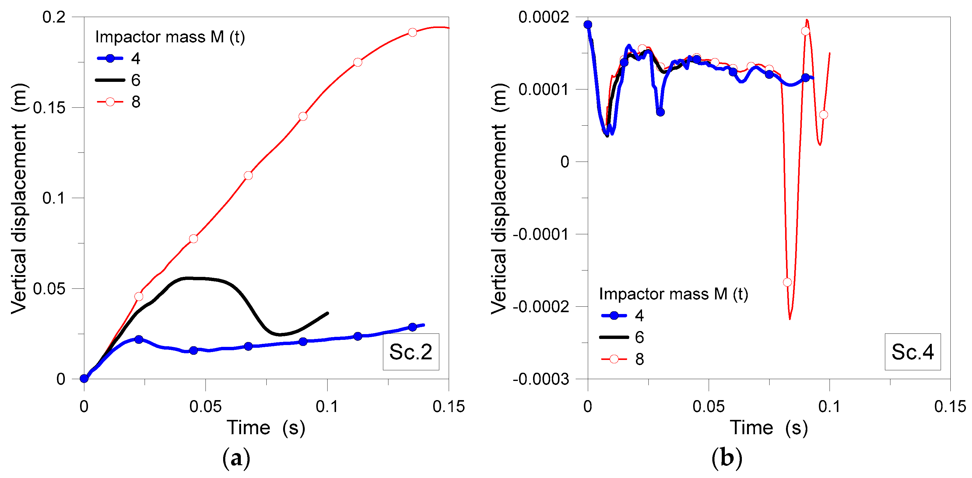
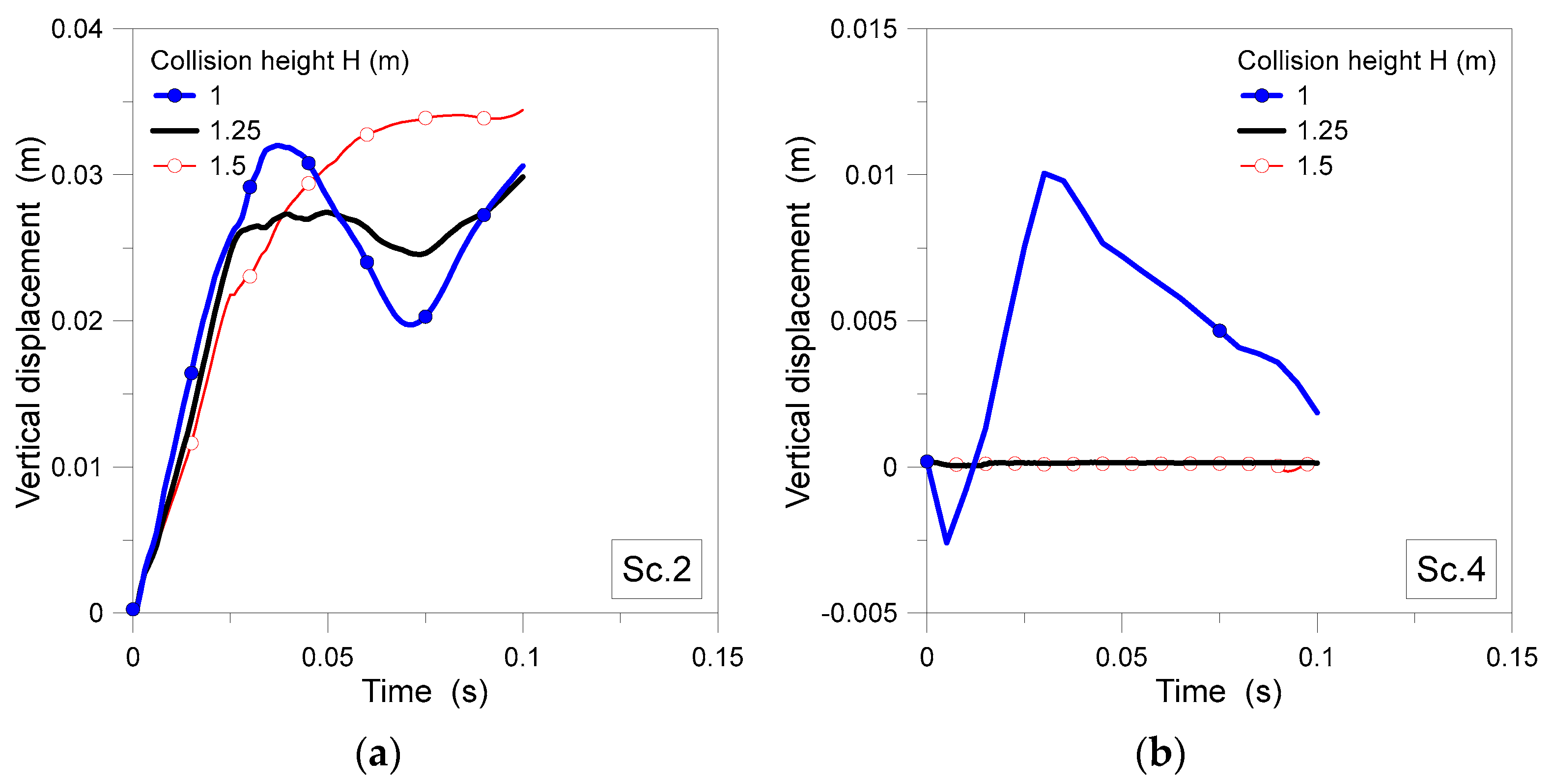
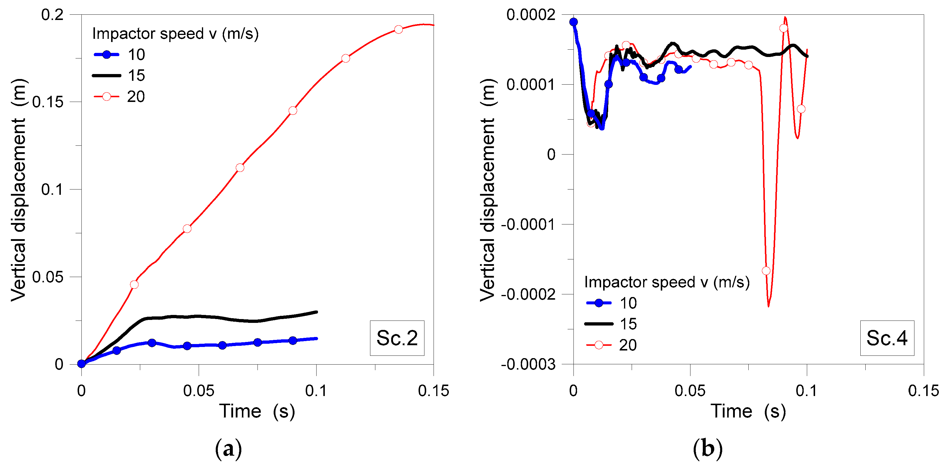
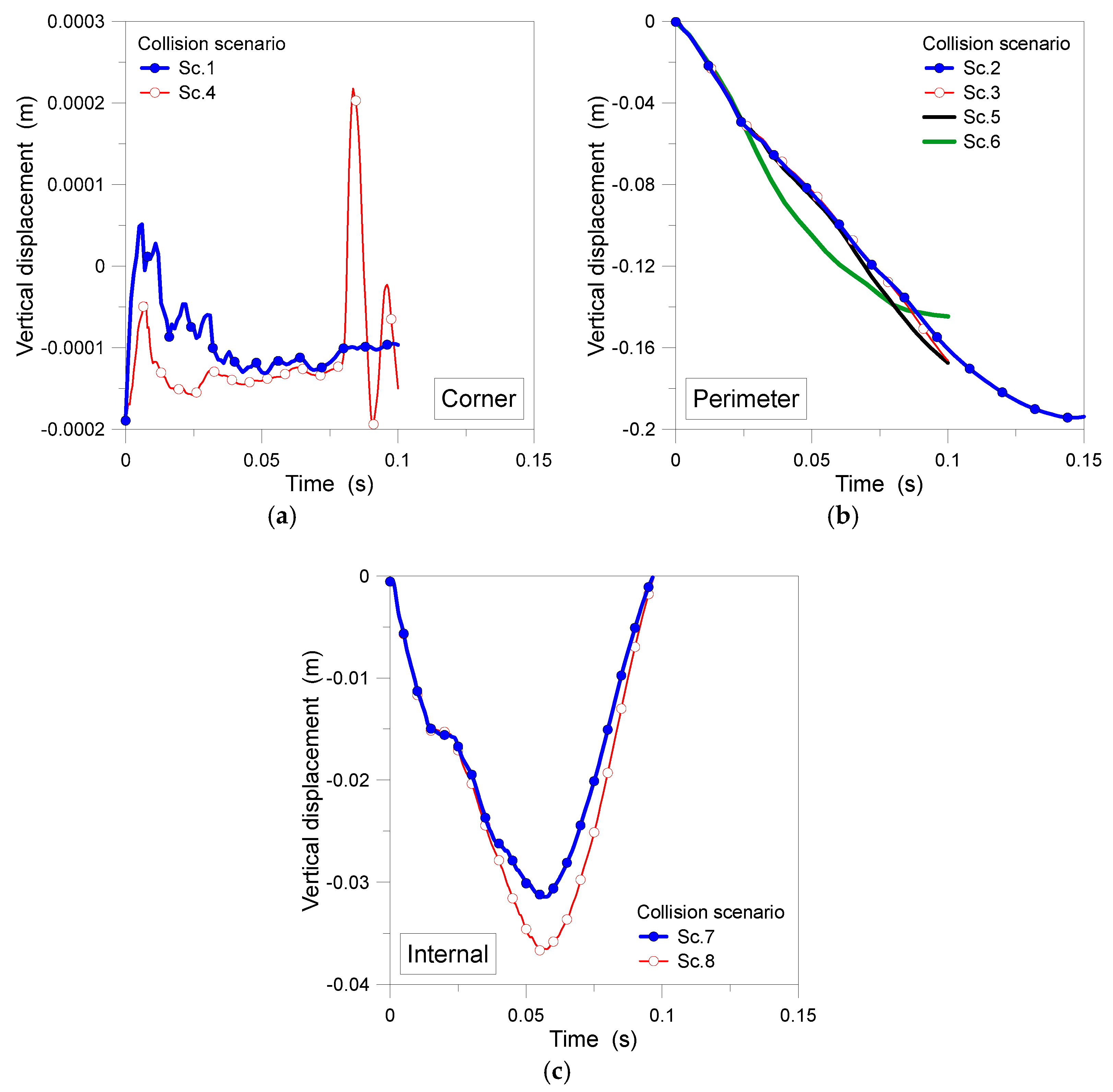
  • By increasing both M and v, due to increased impact energy, the corresponding vertical displacement of the target column clearly increases. The 1 m height from the ground for the truck impactor generally resulted in more critical structural effects, rather than the collision scenarios with H = 1.25 or 1.5 m. By increasing H, the failure mechanism was typically transferred from the base connection towards the top connection of the target column.
  • Target columns adjacent to the braces showed an improved performance against impact load, confirming the bracing system’s positive effect. In structures with dual systems like in the present investigation, where the braces were located at the corners, the perimeter columns were more vulnerable than the corner columns. Whereas, according to literature studies, corner columns of structures with moment frames were generally more vulnerable to truck collision, rather than perimeter columns.
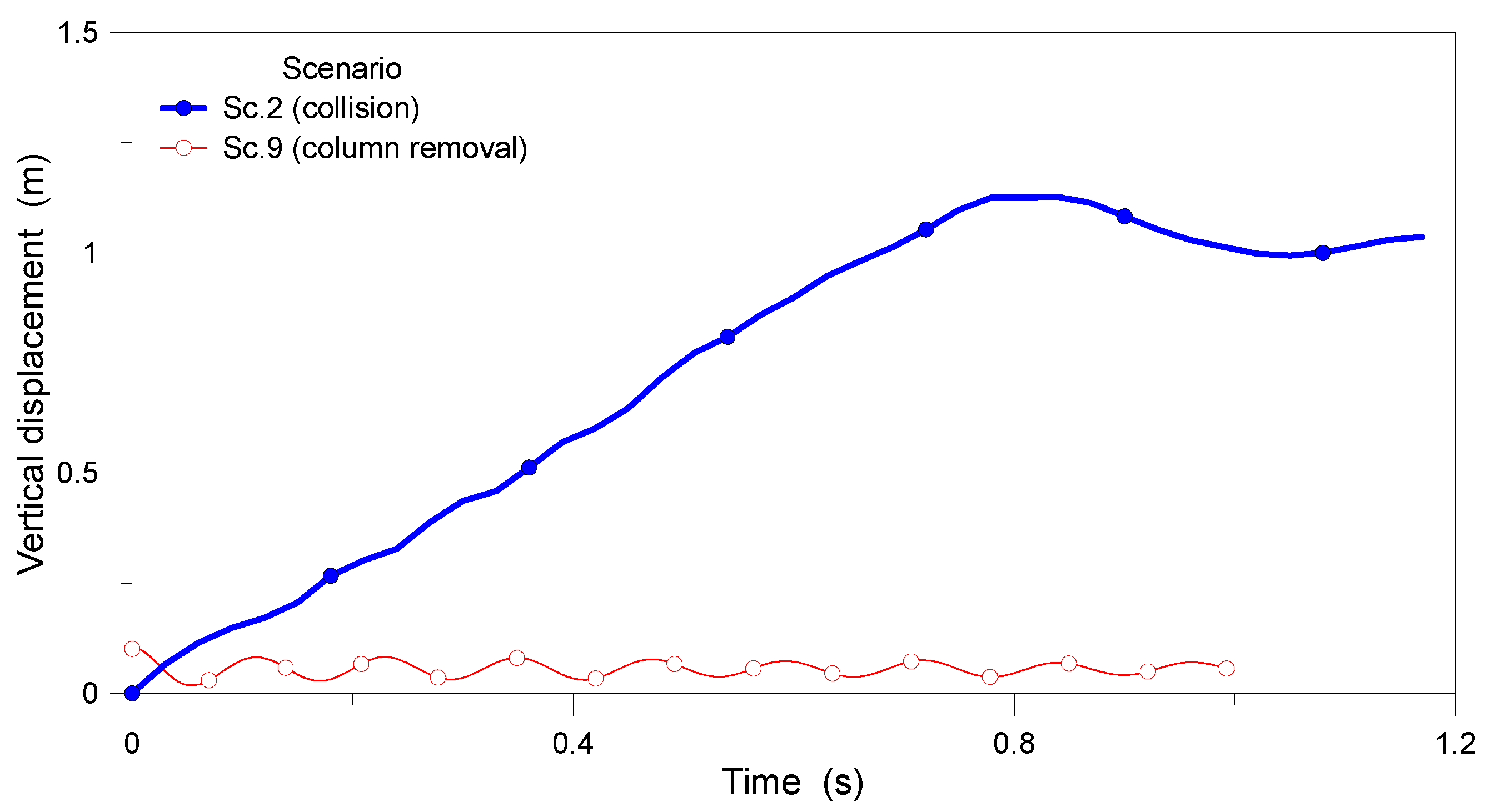
  • The collected displacement time histories showed progressive collapse occurring in the herein-defined Sc. 2 configuration of vehicle impact. However, it must be noted that the structure—when investigated based on the sudden removal of the perimeter column (as in the AP analysis approach, Sc. 9)—manifested a stable post-impact behaviour, which contrasted with the more sophisticated collision simulation. This finding confirmed the importance of refined numerical analyses (both in terms of structural description and impact loading definition) to assess the progressive collapse of buildings. For the present example, the maximum vertical displacement of the corresponding target column was measured in approximately 10 times the maximum vertical displacement of the same member, but based on the simplified AP approach.
  • For most examined configurations, the panel zone at the top of target columns was generally observed to undergo large plastic deformations, with direct consequences on the connected beams and the residual structural capacity. On the other side, current codes operate without removing the panel zone at the top of target columns. This suggests that simplified assessment approaches are not sufficiently conservative (especially when the involved mass is relatively high) and need further refinement.
  • In order to extend further the present investigation outcomes, it is necessary to determine the probabilistic analysis of collision failure for various structural systems and impact configurations. Furthermore, for future studies on progressive collapse, it would be beneficial to investigate the impact of structural diaphragms in buildings subjected to vehicle impact. However, it is important to note that a major limitation of the present study is represented by the simplification of the vehicle model as a rigid body. Such an assumption excludes any possible consideration of energy dissipation within the vehicle, and hence results in a more conservative approach for the overall damage and collapse analysis. Future studies, in this regard, could potentially incorporate more detailed and realistic vehicle modelling strategies.

Author Contributions

F.S.H.: Conceptualization, software, data curation, visualization, investigation, validation, writing—original draft preparation. V.B.: Supervision, methodology, writing—reviewing and editing. E.M.D.: Conceptualization, methodology, software, investigation, visualization, validation, data curation, writing—reviewing and editing. C.B.: Investigation, data curation, writing—reviewing and editing. All authors have read and agreed to the published version of the manuscript.

Funding

This research was not funded by any funding bodies.

Data Availability Statement

Data will be made available upon reasonable request to the authors.

Acknowledgments

The authors would like to sincerely thank the Chen Li for his valuable advice to the project. His support is gratefully acknowledged.

Conflicts of Interest

The authors declare no conflict of interest.

References

  1. ASCE. Minimum Design Loads for Buildings and Other Structures; American Society of Civil Engineers: Reston, VA, USA, 2013. [Google Scholar]
  2. Pearson, C.; Delatte, N. Ronan Point apartment tower collapse and its effect on building codes. J. Perform. Constr. Facil. 2005, 19, 172–177. [Google Scholar] [CrossRef] [Green Version]
  3. Schellhammer, J.; Delatte, N.; Bosela, P. Another Look at the Collapse of Skyline Plaza at Bailey’s Crossroads, Virginia. J. Perform. Constr. Facil. 2013, 27, 354–361. [Google Scholar] [CrossRef] [Green Version]
  4. AISC. American Institute of Steel Construction; AISC: Chicago, IL, USA, 2016. [Google Scholar]
  5. Adam, J.M.; Parisi, F.; Sagaseta, J.; Lu, X. Research and practice on progressive collapse and robustness of building structures in the 21st century. Eng. Struct. 2018, 173, 122–149. [Google Scholar] [CrossRef]
  6. Russell, J.M.; Sagaseta, J.; Cormie, D.; Jones, A.E.K. Historical review of prescriptive design rules for robustness after the collapse of Ronan Point. In Structures; Elsevier: Amsterdam, The Netherlands, 2019; Volume 20, pp. 365–373. [Google Scholar]
  7. Jiang, J.; Zhang, Q.; Li, L.; Chen, W.; Ye, J.; Li, G.Q. Review on quantitative measures of robustness for building structures against disproportionate collapse. Int. J. High-Rise Build. 2020, 9, 127–154. [Google Scholar]
  8. Kiakojouri, F.; De Biagi, V.; Chiaia, B.; Sheidaii, M.R. Progressive collapse of framed building structures: Current knowledge and future prospects. Eng. Struct. 2020, 206, 110061. [Google Scholar] [CrossRef]
  9. Ferrer, B.; Ivorra, S.; Segovia-Eulogio, E.G.; Irles Más, R. Impact Load in Parking Steel Column: Code Review and Numerical Approach; Institute of Structural Analysis & Seismic Research, National Technical University of Athens: Athens, Greece, 2009. [Google Scholar]
  10. Al-Thairy, H.A.; Wang, Y. Behaviour and Design of Steel Columns Subjected to Vehicle Impact; Trans Tech Publications Ltd.: Stafa-Zurich, Switzerland, 2014; Volume 566, pp. 193–198. [Google Scholar]
  11. Cao, R.; El-Tawil, S.; Agrawal, A.K.; Xu, X.; Wong, W. Behavior and design of bridge piers subjected to heavy truck collision. J. Bridge Eng. 2019, 24, 04019057. [Google Scholar] [CrossRef]
  12. Auyeung, S.; Alipour, A.; Saini, D. Performance-based design of bridge piers under vehicle collision. Eng. Struct. 2019, 191, 752–765. [Google Scholar] [CrossRef]
  13. Safari Honar, F.; Mohammadi Dehcheshmeh, E.; Broujerdian, V.; Torabi, M. Nonlinear Dynamic Behavior of Three-Dimensional Moment Steel Frames and Dual System under Vehicle Impact. Civ. Infrastruct. Res. 2022, 7, 21–31. [Google Scholar]
  14. Siadati, S.R.; Broujerdian, V.; Mohammadi Dehcheshmeh, E. Evaluation of intermediate reinforced concrete moment frame subjected to truck collision. J. Rehabil. Civ. Eng. 2022, 10, 64–80. [Google Scholar]
  15. Bandyopadhyay, M.; Banik, A.K.; Datta, T.K. Progressive collapse of three-dimensional semi-rigid jointed steel frames. J. Perform. Constr. Facil. 2016, 30, 04015051. [Google Scholar] [CrossRef]
  16. Kiakojouri, F.; Sheidaii, M.R.; De Biagi, V.; Chiaia, B. Progressive collapse assessment of steel moment-resisting frames using static-and dynamic-incremental analyses. J. Perform. Constr. Facil. 2020, 34, 04020025. [Google Scholar] [CrossRef]
  17. Fu, F. Progressive collapse analysis of high-rise building with 3-D finite element modeling method. J. Constr. Steel Res. 2009, 65, 1269–1278. [Google Scholar] [CrossRef]
  18. Mohamed, O.; Khattab, R. Assessment of progressive collapse resistance of steel structures with moment resisting frames. Buildings 2019, 9, 19. [Google Scholar] [CrossRef] [Green Version]
  19. Mirkarimi, S.P.; Mohammadi Dehcheshmeh, E.; Broujerdian, V. Investigating the Progressive Collapse of Steel Frames Considering Vehicle Impact Dynamics. Iran. J. Sci. Technol. Trans. Civ. Eng. 2022, 46, 4463–4479. [Google Scholar] [CrossRef]
  20. Tsitos, A.; Mosqueda, G.; Filiatrault, A.; Reinhorn, A.M. Experimental investigation of progressive collapse of steel frames under multi-hazard extreme loading. In Proceedings of the 14th World Conference on Earthquake Engineering, Beijing, China, 12–17 October 2008. [Google Scholar]
  21. Kordbagh, B.; Mohammadi, M. Influence of panel zone on progressive collapse resistance of steel structures. J. Perform. Constr. Facil. 2018, 32, 04018014. [Google Scholar] [CrossRef]
  22. Rezvani, F.H.; Yousefi, A.M.; Ronagh, H.R. Effect of span length on progressive collapse behaviour of steel moment resisting frames. In Structures; Elsevier: Amsterdam, The Netherlands, 2015; Volume 3, pp. 81–89. [Google Scholar]
  23. Shah, B.; Xu, F. Effects of Steel Bracings in the Progressive Collapse Resistance of Reinforced Concrete Building. In IOP Conference Series: Materials Science and Engineering; IOP Publishing: Bristol, UK, 2020; Volume 758, p. 012092. [Google Scholar]
  24. Qian, K.; Lan, X.; Li, Z.; Li, Y.; Fu, F. Progressive collapse resistance of two-storey seismic configured steel sub-frames using welded connections. J. Constr. Steel Res. 2020, 170, 106117. [Google Scholar] [CrossRef]
  25. Faghihmaleki, H.; Nejati, F.; Zarkandy, S.; Masoumi, H. Evaluation of progressive collapse in steel moment frame with different braces. Jordan J. Civ. Eng. 2017, 11, 290–298. [Google Scholar]
  26. Liu, Z.; Zhu, Y. Progressive collapse of steel frame-brace structure under a column-removal scenario. In IOP Conference Series: Earth and Environmental Science; IOP Publishing: Bristol, UK, 2019; Volume 218, p. 012083. [Google Scholar]
  27. Jiang, J.; Li, G.Q. Mitigation of fire-induced progressive collapse of steel framed structures using bracing systems. Adv. Steel Constr. 2019, 15, 192–202. [Google Scholar]
  28. Salmasi, A.C.; Sheidaii, M.R. Assessment of eccentrically braced frames strength against progressive collapse. Int. J. Steel Struct. 2017, 17, 543–551. [Google Scholar] [CrossRef]
  29. Kang, H.; Kim, J. Progressive collapse of steel moment frames subjected to vehicle impact. J. Perform. Constr. Facil. 2015, 29, 04014172. [Google Scholar] [CrossRef] [Green Version]
  30. Cravotta, S.; Grimolizzi, E. Simulation of vehicle impact into a steel building: A parametric study on the impacted column end-connections. Master’s Thesis, School of Architecture and the Built Environment, Singapore, 2015. [Google Scholar]
  31. Broujerdian, V.; Torabi, M. A Parametric Study on the Progressive Collapse Potential of Steel Buildings under Truck Collision. J. Rehabil. Civ. Eng. 2017, 5, 96–106. [Google Scholar]
  32. Jahromi, H.Z.; Izzuddin, B.A.; Nethercot, D.A.; Donahue, S.; Hadjioannou, M.; Williamson, E.B.; Engelhardt, M.; Stevens, D.; Marchand, K.; Waggoner, M. Robustness assessment of building structures under explosion. Buildings 2012, 2, 497–518. [Google Scholar] [CrossRef] [Green Version]
  33. Stochino, F.; Bedon, C.; Sagaseta, J.; Honfi, D. Robustness and Resilience of Structures under Extreme Loads. Adv. Civ. Eng. 2019, 2019, 4291703. [Google Scholar] [CrossRef] [Green Version]
  34. Figuli, L.; Bedon, C.; Zvaková, Z.; Kavický, V. Dynamic analysis of a blast loaded steel structure. Procedia Eng. 2017, 199, 2463–2469. [Google Scholar] [CrossRef] [Green Version]
  35. Momeni, M.; Hadianfard, M.; Bedon, C.; Baghlani, A. Numerical damage evaluation assessment of blast loaded steel columns with similar section properties. Structures 2019, 20, 189–203. [Google Scholar] [CrossRef]
  36. GSA. Alternate Path Analysis and Design Guidelines for Progressive Collapse Resistance; US General Service Administration: Washington, DC, USA, 2016.
  37. ETABS. User’s Manual; Computers and Structures, Inc.: Berkeley, CA, USA, 2015. [Google Scholar]
  38. Standard No. 2800; Iranian Code of Practice for Seismic Resistant Design of Buildings, 4th ed. IBCS (Iranian Building Codes and Standards): Tehran, Iran, 2013.
  39. ABAQUS/CAE Computer Software, v. 6.14; Dassault Systémes, Inc.: Providence, RI, USA, 2014; pp. 1–1146.
  40. Zeinoddini, M.; Parke, G.A.R.; Harding, J.E. Axially pre-loaded steel tubes subjected to lateral impacts: An experimental study. Int. J. Impact Eng. 2002, 27, 669–690. [Google Scholar] [CrossRef]
  41. Bambach, M.R.; Jama, H.; Zhao, X.L.; Grzebieta, R.H. Hollow and concrete filled steel hollow sections under transverse impact loads. Eng. Struct. 2008, 30, 2859–2870. [Google Scholar] [CrossRef]
  42. Al-Thairy, H.; Wang, Y.C. A numerical study of the behaviour and failure modes of axially compressed steel columns subjected to transverse impact. Int. J. Impact Eng. 2011, 38, 732–744. [Google Scholar] [CrossRef] [Green Version]
  43. Jilin, Y.; Norman, J. Further experimental investigations on the failure of clamped beams under impact loads. Int. J. Solids Struct. 1991, 27, 1113–1137. [Google Scholar] [CrossRef]
  44. Yu, J.L.; Jones, N. Numerical simulation of impact loaded steel beams and the failure criteria. Int. J. Solids Struct. 1997, 34, 3977–4004. [Google Scholar] [CrossRef]
  45. Poursadrollah, A.; D’Aniello, M.; Landolfo, R. Experimental and numerical tests of cold-formed square and rectangular hollow columns. Eng. Struct. 2022, 273, 115095. [Google Scholar] [CrossRef]
  46. UFC, Unified Facilities Criteria; National Institute of Building Sciences: Washington, DC, USA, 2016.
  47. GSA. Progressive Collapse Analysis and Design Guidelines for New Federal Office Buildings and Major Modernization Projects; US General Service Administration: Washington DC, USA, 2003.
Figure 1. Geometrical details for the examined 4-story steel structure: (a) floor plan and (b) three-dimensional axonometric view (ETABS).
Buildings 13 01545 g001
Figure 2. Finite element model of tube-channel beam under impact (ABAQUS).
Buildings 13 01545 g002
Figure 3. Global plastic buckling failure validation: (a) comparison of present numerical results with literature experiments and (b) corresponding deformed shape for P/Py = 0.6 (side view).
Buildings 13 01545 g003
Figure 4. Benchmark for tensile (tearing) failure: (a) experimental deformation pattern, with (b) numerical and (c) present numerical stress contours, and (d) time history of ductile damage parameter versus time (impact region).
Buildings 13 01545 g004
Figure 5. True stress–true strain curve of steel plastic behaviour.
Buildings 13 01545 g005
Figure 6. Deformed shape of target steel beam after shear failure: (a) experimental test and (b) present numerical simulation, with legend values in Pa (ABAQUS).
Buildings 13 01545 g006
Figure 7. Comparison of axial strain on the lower beam surface (underneath the impactor), as obtained from the reference experiment and from present numerical simulation (ABAQUS).
Buildings 13 01545 g007
Figure 8. Numerical model for collision analysis in ABAQUS: (a) truck bumper and (b) axonometric view of the 4-story steel structure.
Buildings 13 01545 g008
Figure 9. Schematic view of different scenarios (“Sc.”) taken into account in present numerical study for vehicle collision analysis (plan view).
Buildings 13 01545 g009
Figure 10. Vertical displacement versus time, with v = 20 m/s and H = 1.25 m, for (a) Sc. 2 and (b) Sc. 4 configurations.
Buildings 13 01545 g010
Figure 11. Vertical displacement versus time, with M = 8 ton and H = 1.25 m, for (a) Sc. 2 and (b) Sc. 4 configurations.
Buildings 13 01545 g011
Figure 12. Vertical displacement versus time, with M = 8 t and H = 1.25 m, for (a) Sc. 2 and (b) Sc. 4 configurations.
Buildings 13 01545 g012
Figure 13. Von Mises stress distribution in steel members, with M= 8 t and H= 1.25 m: (a) Sc. 1, (b) Sc. 2, (c) Sc. 3, (d) Sc. 4, (e) Sc. 5, (f) Sc. 6, (g) Sc. 7 and (h) Sc. 8 configurations. Legend values in Pa.
Buildings 13 01545 g013
Figure 14. Vertical displacement, with M = 8 t, H = 1.25 m and v = 20 m/s, for (a) corner, (b) perimeter and (c) internal columns (selected collision scenarios).
Buildings 13 01545 g014
Figure 15. Measured impact force in the target column, under different collision scenarios.
Buildings 13 01545 g015
Figure 16. Vertical displacement, with M = 8 t, H = 1.25 m and v = 20 m/s, based on simplified AP approach and sudden column removal (Sc. 9) or corresponding collision analysis (Sc. 2).
Buildings 13 01545 g016
Table 1. Specifications of structural elements for the examined 4-story steel structure.
StoryColumnsBeamsSub-BeamsBraces
1 to 2C300X12F300X12-W220X12IPE180-IPE2002UNP120
3 to 4C250X10F300X8-W200X12IPE180-IPE2002UNP100
Table 2. Comparison of experimental and numerical behaviour for the steel beam at failure.
Experimental
[43]
Numerical
[44]
Numerical
(Present)
Maximum permanent displacement (mm)21.8021.2621.72
Table 3. Summary of input parameters for the Sc. 1-to-8 selected collision scenarios.
Mass M
(t)
Velocity v
(m/s)
Impact Point Height H
(m)
4, 6 and 8201.25
810, 15 and 201.25
8151, 1.25 and 1.5
Table 4. Failure criteria for structural steel elements subjected to extreme loads.
Damage
ElementMaterial
Properties
Failure TypeParameterLight
(%)
Moderate
(%)
Severe
(%)
BeamSteelBending/
Membrane response
δ/L51225
Column Shear
Compression
γ ϑ
ΔL/L
2
2
4
4
8
8
Note: δ/L = ratio of centre line deflection to span; γ ϑ = average shear strain across section; ΔL/L = ratio of shortening to height.
Table 5. Observed failure modes for target column in Sc. 2 and Sc. 4 configurations.
Sc.ParameterTopBottomImpact ZoneTopBottomImpact ZoneTopBottomImpact Zone
M (t)468
2 NTNNTNNTN
4 NTSNTSNTS
v (m/s)101520
2 NNNNTSNTN
4 NTSNTSNTS
H (m)11.251.5
2 NTNNTSNTS
4 NTNNTSNTS
Note: N = No failure, T = Tensile failure, S = Shear failure.
Table 6. Observed failure modes for various collision scenarios.
Scenario
Location12345678
TopNNNNNNTT
BottomTTTTTTTT
Impacted zoneSNNSSNNN
Panel zone (local)EPPEEPEE
Note: N = No failure, T = Tensile failure, S = Shear failure, E = Elastic, P = Plastic.
Disclaimer/Publisher’s Note: The statements, opinions and data contained in all publications are solely those of the individual author(s) and contributor(s) and not of MDPI and/or the editor(s). MDPI and/or the editor(s) disclaim responsibility for any injury to people or property resulting from any ideas, methods, instructions or products referred to in the content.

