Article

Structural Performance of Internally Stiffened Double-Skinned Profiled Composite Walls with Openings

by
Salam J. Hilo
1,
Mohammed J. Hamood
1,
Alaa Hussein Al-Zuhairi
2,
Ahmed W. Al Zand
3,*,
A. B. M. A. Kaish
3,
Mustafa M. Ali
4,
Marwah M. Faris
5 and
Wan Hamidon W. Badaruzzaman
3
1
Civil Engineering Department, University of Technology-Iraq, Baghdad 10066, Iraq
2
Department of Civil Engineering, University of Baghdad, Baghdad 10071, Iraq
3
Department of Civil Engineering, Universiti Kebangsaan Malaysia (UKM), Bangi 43600, Malaysia
4
Department of Civil Engineering, College of Engineering, University of Kerbala, Karbala 56001, Iraq
5
Department of Architecture and Civil Engineering, Chalmers University of Technology, 412 96 Gothenburg, Sweden
*
Author to whom correspondence should be addressed.
Buildings 2023, 13(6), 1499; https://doi.org/10.3390/buildings13061499
Submission received: 8 May 2023 / Revised: 8 June 2023 / Accepted: 9 June 2023 / Published: 10 June 2023
(This article belongs to the Section Building Materials, and Repair & Renovation)

Abstract

:
The double-skin profiled composite wall (DSPCW) system, filled with concrete material, is favorable in modern structures due to its high strength and ductility. Openings may be required within this composite wall (DSPCW) for various reasons, similar to a conventional bearing wall, which can lead to a reduction in bearing capacity. Therefore, to avoid changes in the geometry, materials, and thickness of this DSPCW wall, a new internally stiffening concept has been suggested by providing embedded cold-formed steel tube (CFST) columns. For this purpose, two full-scale DSPCW specimens were tested under static axial load, one of which was fabricated with a large opening size and stiffened with two octagonal CFST columns, while the other was designed without an opening and served as a control wall specimen. The results showed that the stiffened DSPCW with an opening achieved a slightly lower ultimate bearing strength (−9.4%) than the control wall specimen, with no reduction in the ductility behavior. Furthermore, several finite element models of DSPCW have been analyzed and designed to investigate additional parameters that were not experimentally tested, including the effects of the embedded CFST column’s shape and different types of internal stiffeners longitudinally provided inside these columns. The numerical investigation confirmed that the embedded CFST column with an octagonal cross-section was more efficient compared to the hexagonal and rectangular shapes by about 11% and 18.4%, respectively. Furthermore, using internal steel stiffeners for embedded tubes with a T-shape improved the axial bearing capacity of the DSPCW with an opening slightly higher than the corresponding stiffened walls with other investigated stiffener shapes (V-shaped, U-shaped, and L-shaped).

1. Introduction

In building structures, traditional walls such as masonry or reinforced concrete bearing walls have been widely used as axial load-resisting systems [1,2]. However, the double-skinned profiled composite wall (DSPCW) system, consisting of two profiled steel sheets (PSS) filled with concrete, has emerged as a more efficient alternative [3,4,5,6]. Additionally, the PSS serves as fixed formwork during construction and as a bracing system for the structure frame against axial loads during service [7,8,9,10]. The DSPCW not only serves as a load-bearing element but also acts as a retaining and shear wall, offering significant advantages in terms of structural performance and aesthetic appeal [11,12,13,14]. Despite its many benefits, the presence of openings in DSPCWs can significantly impact their axial load resistance, potentially leading to premature failure [15].
The use of DSPCWs in building construction has gained popularity in recent years due to their excellent structural performance and aesthetic appeal [16,17]. Specifically, with the increasing use of DSPCWs, extensive experimental, numerical, and analytical studies have been conducted. Tong et al. [18] studied the analytical and numerical behavior of PDSCWs with re-entrant profiled faceplates when subjected to eccentric compression. They also developed a sectional analysis approach to establish the N-M relationship for PDSCWs under compression and bending forces. The researchers found their proposed analytical method and the resulting N-M relationship to be reliable and suitable for designing PDSCWs with re-entrant profiled faceplates. In 2022, Li et al. [19] conducted research to examine the compressive behavior of a new type of wall made of shallow-corrugated steel plates filled with concrete, along with rectangular steel columns that are also filled with concrete. The investigation involved both full-scale tests and numerical models. Parametric studies were conducted to suggest formulas for predicting the wall’s resistance. The study found the formulas to be reliable in determining the wall’s resistance to compression, the equivalent slenderness ratio, stability coefficient, and cross-sectional resistance in axial compression. Wang et al. [20] studied the behavior of DSCW under axial compression through full-scale tests and analytical analysis. DSCW showed high axial load-carrying capacity and satisfactory displacement ductility, with a global buckling failure mode. The study proposed a nonlinear FE model and formulas for predicting and calculating the axial load-carrying capacity of DSCW, which were validated by test and FEA results. A reliable design method for DSCW under axial load was also proposed. Wang et al. [21] investigated the flexural-torsional buckling behavior of axially loaded T-CDSCWs, which are composed of steel corrugated plates filled with concrete and intermediate bolts with a T-section. The aim of the study was to develop design formulas for flexural-torsional buckling by performing numerical and theoretical analyses of the elastic and inelastic behavior of T-CDSCWs. Based on that, the flexural-torsional instability strength reduction factor in T-CDSCWs can be calculated by considering the web’s height-to-thickness ratio and the normalized torsional slenderness ratio. This discovery provides a basis for further investigation into the global instability of T-CDSCWs under combined compression and bending. Moreover, the recommended design formulas can improve the design process of axially loaded T-CDSCWs.
The importance of investigating the effects of openings on the load-resisting behavior of DSPCWs cannot be overstated. Although some studies have explored this aspect in related composite wall systems conducted by Hossain et al. [22], the study [22] focused on the load-resisting behavior of a new form of pierced double-skin composite wall system. This system was composed of two profiled steel sheeting skins with concrete infill. Nineteen composite walls were tested under axial loading, and various test variables were evaluated. The study found that strengthening the whole boundary was crucial for enhancing axial strength. Furthermore, a theoretical model was developed to predict axial strength in both pierced and non-pierced walls, and the model’s performance was validated by comparing it to experimental results. The study’s findings have practical implications for the design and construction of composite walls that have openings.
Limited research has been conducted specifically on DSPCWs. Therefore, this study aims to fill this gap by investigating the effects of openings on the axial load behavior of DSPCWs and proposing methods to mitigate their negative impacts. Additionally, the effectiveness of strengthening DSPCWs with embedded cold-formed steel tube (CFST) columns will be examined. To achieve these objectives, two DSPCW specimens were designed and assembled, with one specimen featuring an opening and both specimens incorporating embedded octagonal CFST columns. Experimental tests were conducted on these specimens under static axial loads. Furthermore, finite element (FE) models were developed to simulate the tested samples and explore additional parameters that were not experimentally examined [
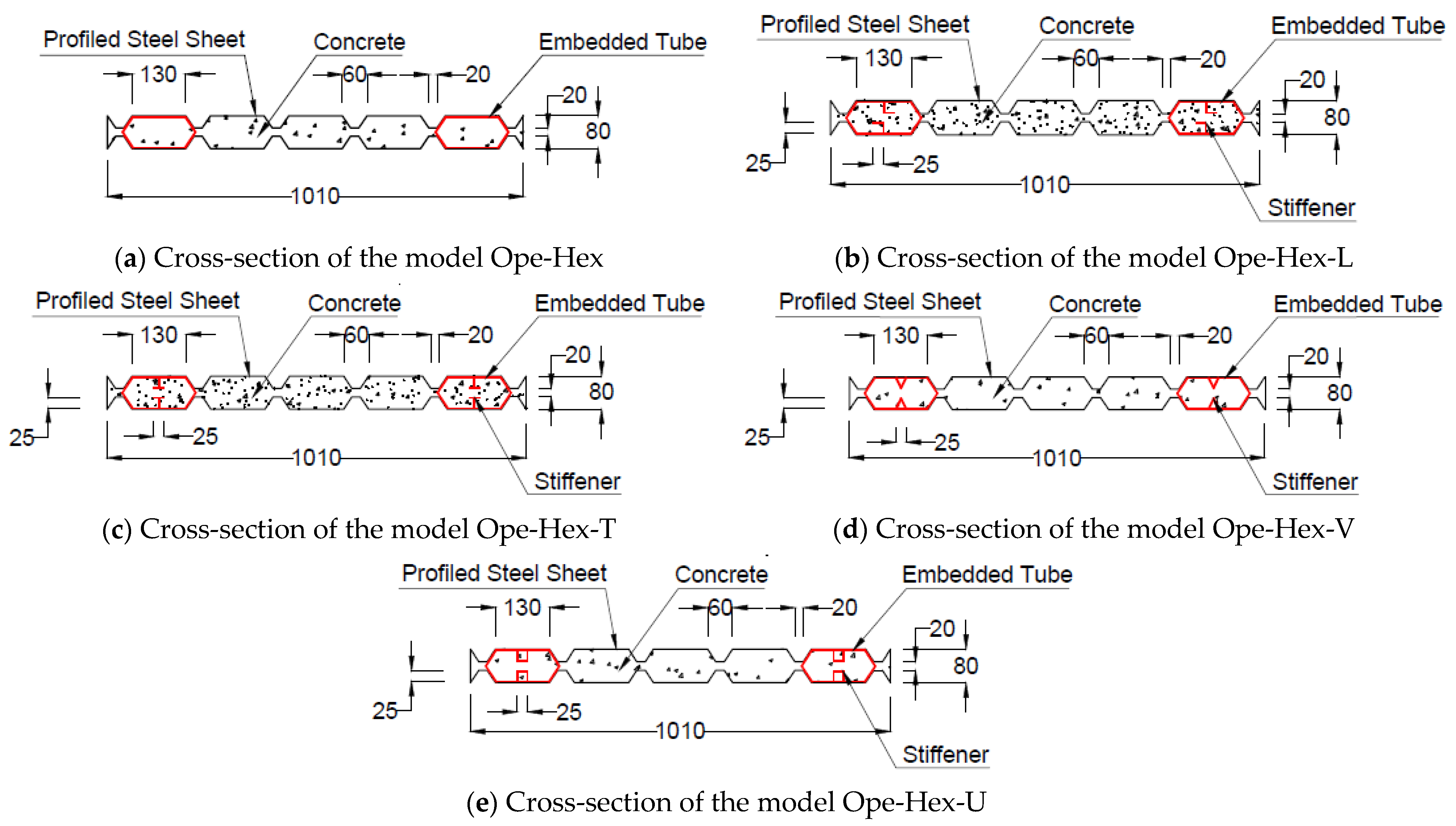
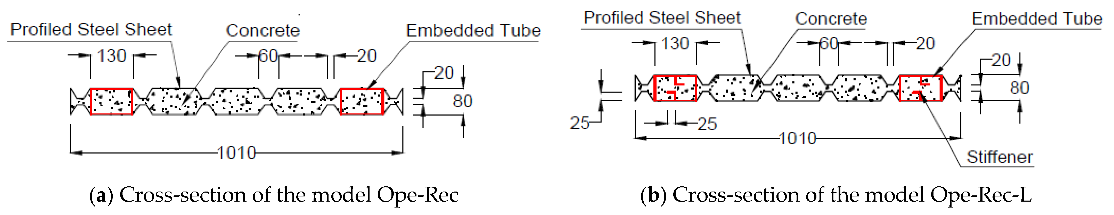
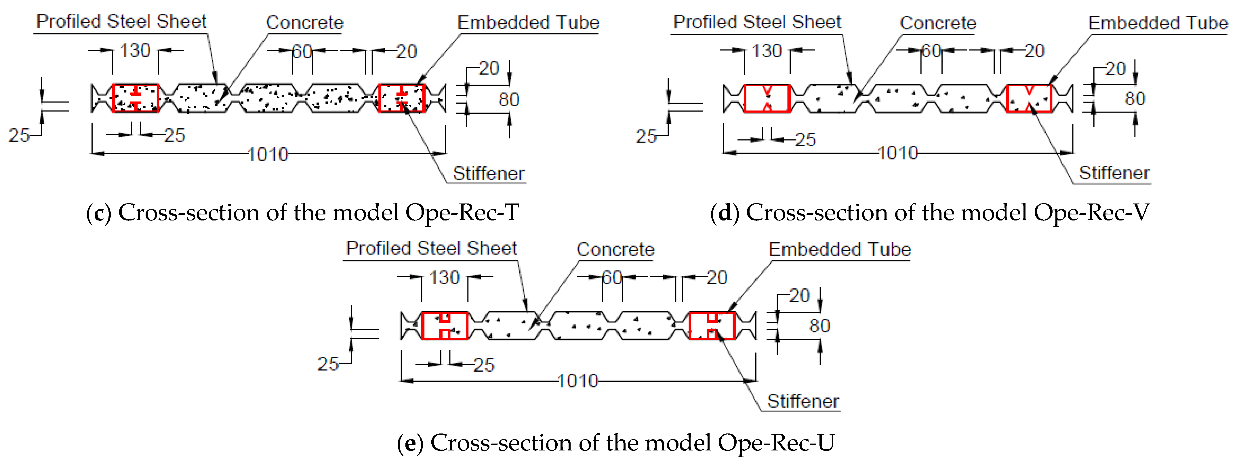
23,24]. These parameters include the influence of different embedded CFST cross-section shapes (octagonal, hexagonal, and rectangular) and the use of internal steel stiffeners (L-shaped, T-shaped, V-shaped, and U-shaped) to strengthen the CFST columns.
By studying the failure mode and ultimate bearing capacities of these DSPCW models, this research aims to provide valuable insights into the behavior and performance of DSPCWs with openings as well as propose design considerations and strategies to enhance their load-resisting capabilities. Overall, this study addresses a significant research gap in the field of DSPCWs, contributes to the understanding of their load-resisting behavior, and provides practical implications for the design and construction of composite walls with openings. The findings of this research will aid in the development of more robust and reliable structures in the realm of modern building construction. Accordingly, this study addresses the need for investigating the effects of openings on the axial load behavior of double-skinned profiled composite walls (DSPCWs). By examining the behavior of DSPCWs with openings and exploring methods to strengthen them using embedded cold-formed steel tube (CFST) columns, this research aims to enhance the load-resisting capabilities of DSPCWs. The findings will provide valuable insights and practical implications for the design and construction of composite walls with openings, contributing to the development of more robust structures in modern building construction.

2. Experimental Approach

2.1. Specimen Preparation

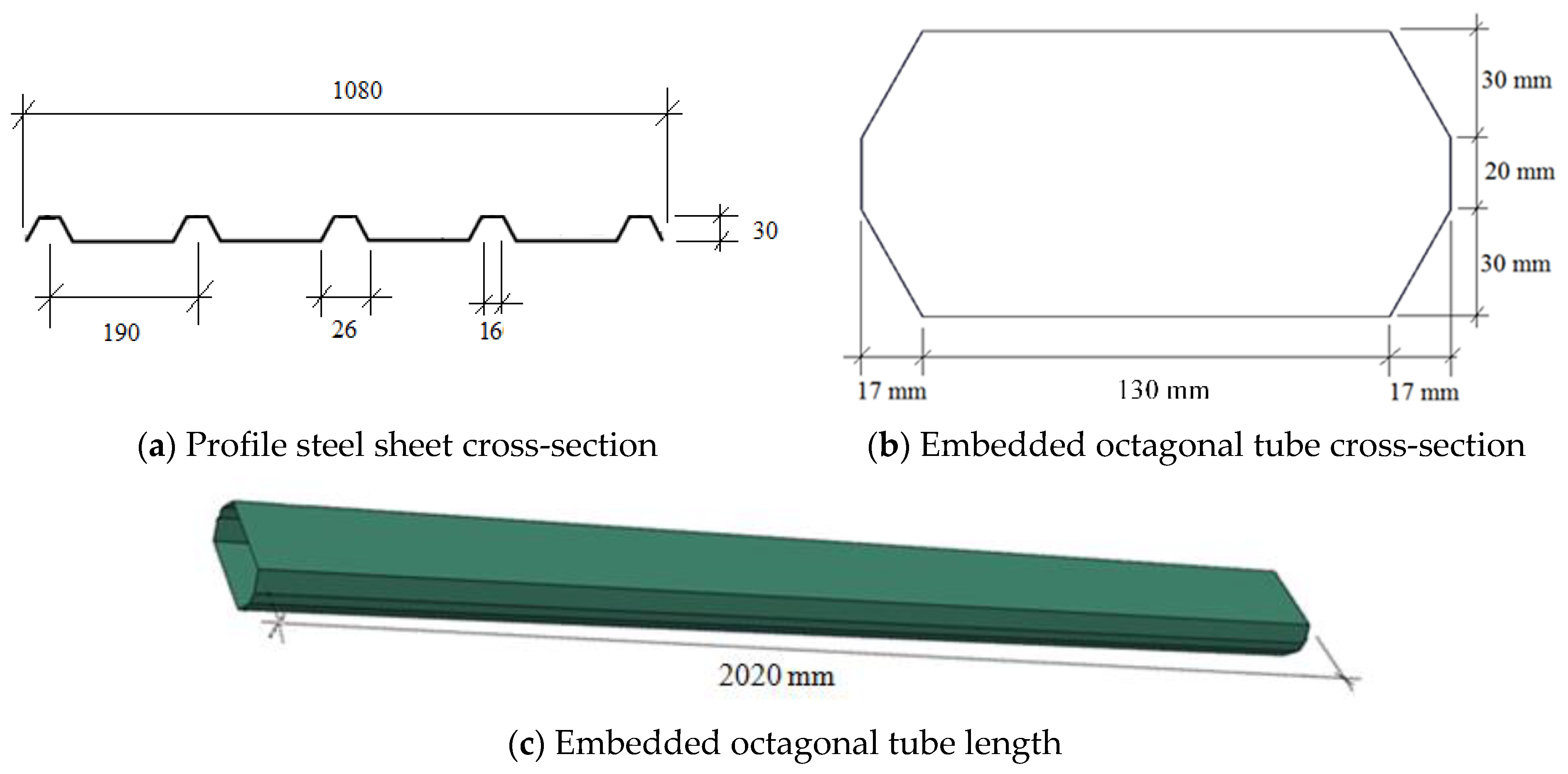
The DSPCW specimens in this research were fabricated using two pieces of PSS connected with bolts and infilled with concrete. Octagonal cold-formed steel tubes (CFSTs) with a thickness of 1 mm were embedded inside these PSSs on the left and right sides of the wall, also infilled with concrete. The cross sections of the steel parts (PSS and octagonal CFST columns) are shown in 
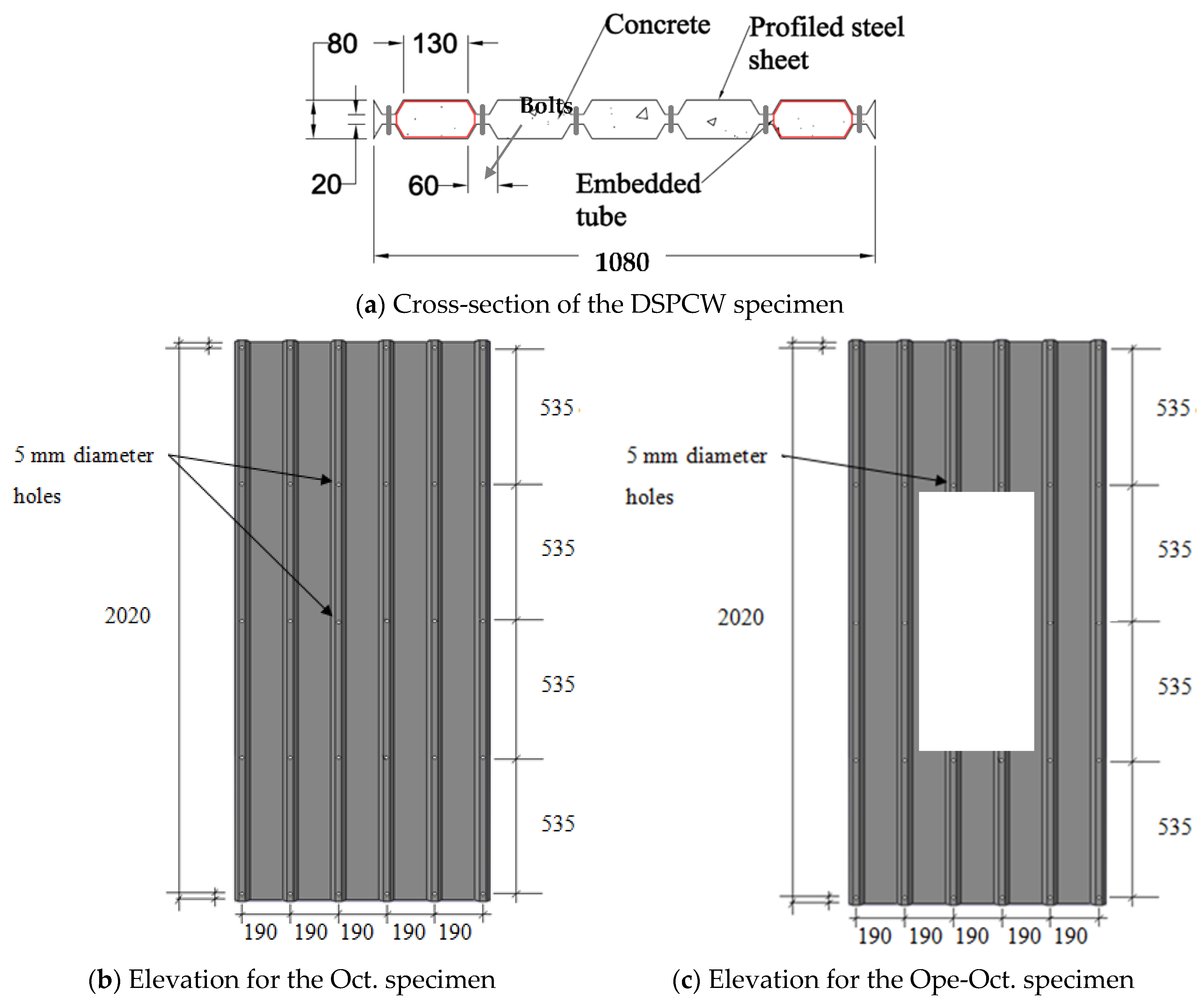
Figure 1. The PSS used for the specimens was Trimdek Optima, manufactured by Bluescope Lysaght Malaysia. The PSSs had an effective width, length, and thickness of 1080 mm, 2200 mm, and 0.5 mm, respectively. The PSSs were bolted face-to-face with a clear spacing of 20 mm. The bolts were provided horizontally at 190 mm intervals and vertically at 535 mm center-to-center, as shown in Figure 2.
The control DSPCW specimen, named “Oct.”, consisted of two PSSs filled with concrete and reinforced with two embedded octagonal CFSTs without openings or stiffeners. The second specimen, named “Ope-Oct.”, was similar to the control specimen (Oct.) but had a rectangular opening measuring 960 × 400 mm. The cross-sections and elevations of the specimens are presented in 
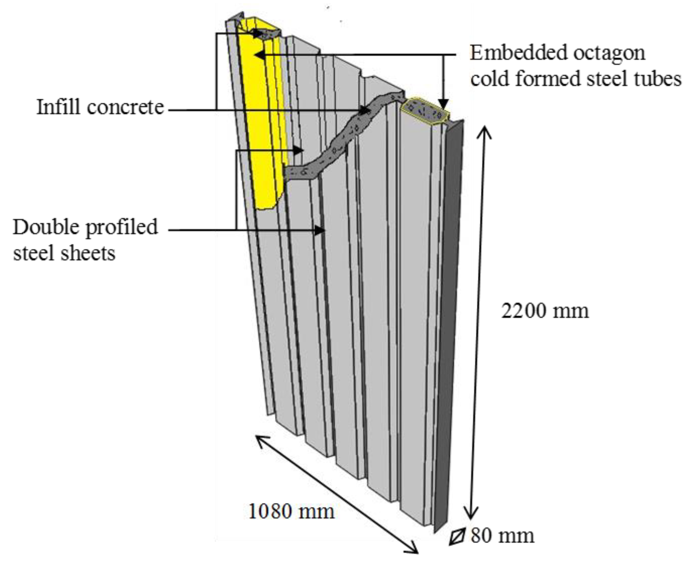
Figure 2a–c. After assembling all the parts, the specimens were filled with concrete poured from the top in continuous steps. An electrical vibrator device was used to ensure the proper distribution of the concrete inside the specimens. The 3-D view and overall dimensions of the DSPCW are shown in Figure 3.
In conclusion, the experimental approach involved fabricating DSPCW specimens using profiled steel sheets (PSS) connected with bolts and filled with concrete. Octagonal cold-formed steel tubes (CFSTs) were embedded inside the PSSs, and two types of specimens were prepared: one without openings or stiffeners (control) and one with a rectangular opening. Concrete was poured into the specimens, ensuring proper distribution using an electrical vibrator device. The experimental setup and specimen details provide a foundation for further analysis and investigation of the load-resisting behavior of the DSPCW system.

2.2. Material Properties

In this study, normal concrete was used as the infill material for the DSPCW specimens, with a mixing proportion of 1:2:3. The compressive strength of the concrete was determined by casting and curing three cubes (150 mm) for 28 days, resulting in an average value of 22.1 MPa. Additionally, three cubes tested at the time of specimen testing achieved a strength of 25.0 MPa. For tensile and modulus of elasticity measurements, three cylinder samples (150 mm × 300 mm) were prepared, yielding average values of 3.3 MPa and 22.457 GPa, respectively.
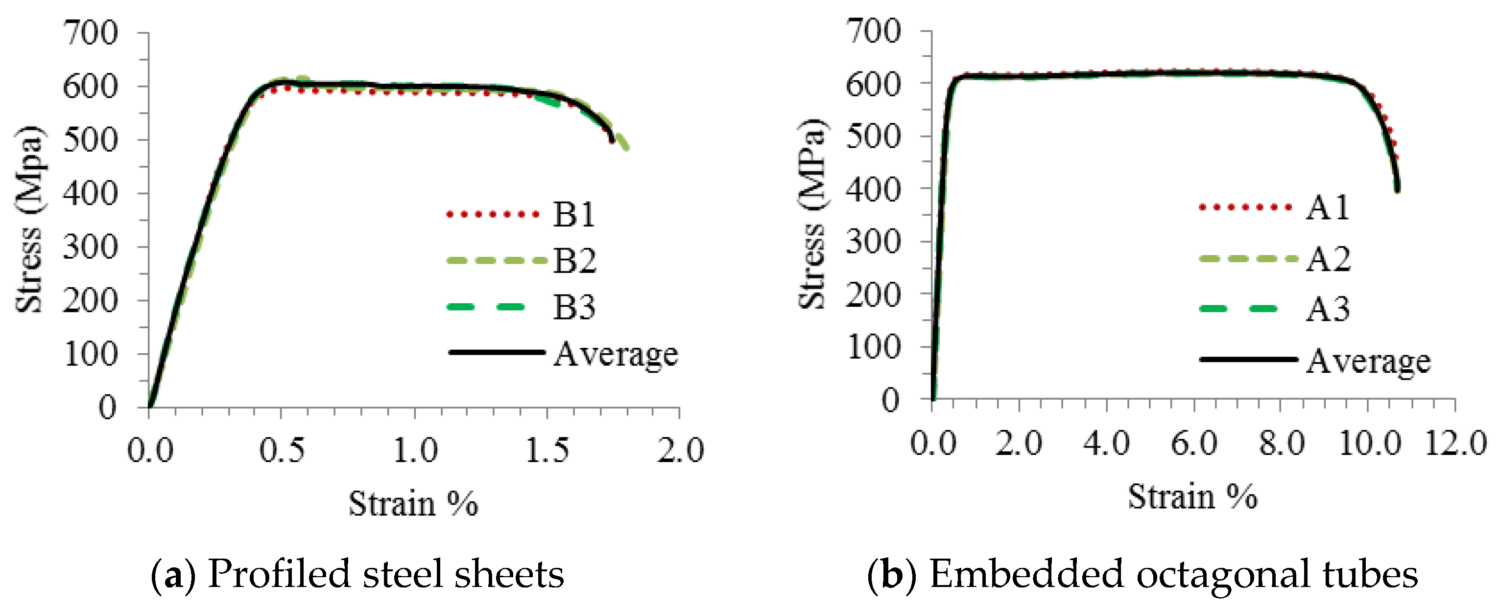
The cold-formed steel sections (PSS and the embedded octagonal tubes) were tested according to ASTM standards E8/E8M-2009 [25]. Three steel coupons were cut and subjected to a direct tensile test. The average yield stress of the PSS was 597 MPa, with an ultimate strength of 615 MPa, a modulus of elasticity of 168,000 MPa, and an elongation of 1.2%. Similarly, the embedded octagon tubes exhibited a yield stress of 605 MPa, an ultimate strength of 622 MPa, a modulus of elasticity of 181,000 MPa, and an elongation of 10.6%. The stress-strain relationship for the tensile coupons of the PSSs and embedded octagonal tubes is shown in Figure 4a and Figure 4b, respectively.
In conclusion, this section determined the material properties of the DSPCW specimens. Normal concrete with a mixing proportion of 1:2:3 exhibited compressive strengths of 22.1 MPa and 25.0 MPa. The cold-formed steel sections (PSS and embedded octagonal tubes) had yield stresses of 597 MPa and 605 MPa, ultimate strengths of 615 MPa and 622 MPa, and moduli of elasticity of 168,000 MPa and 181,000 MPa, respectively. These findings provide essential data for analyzing the structural behavior of the DSPCW system.

2.3. Test Setup

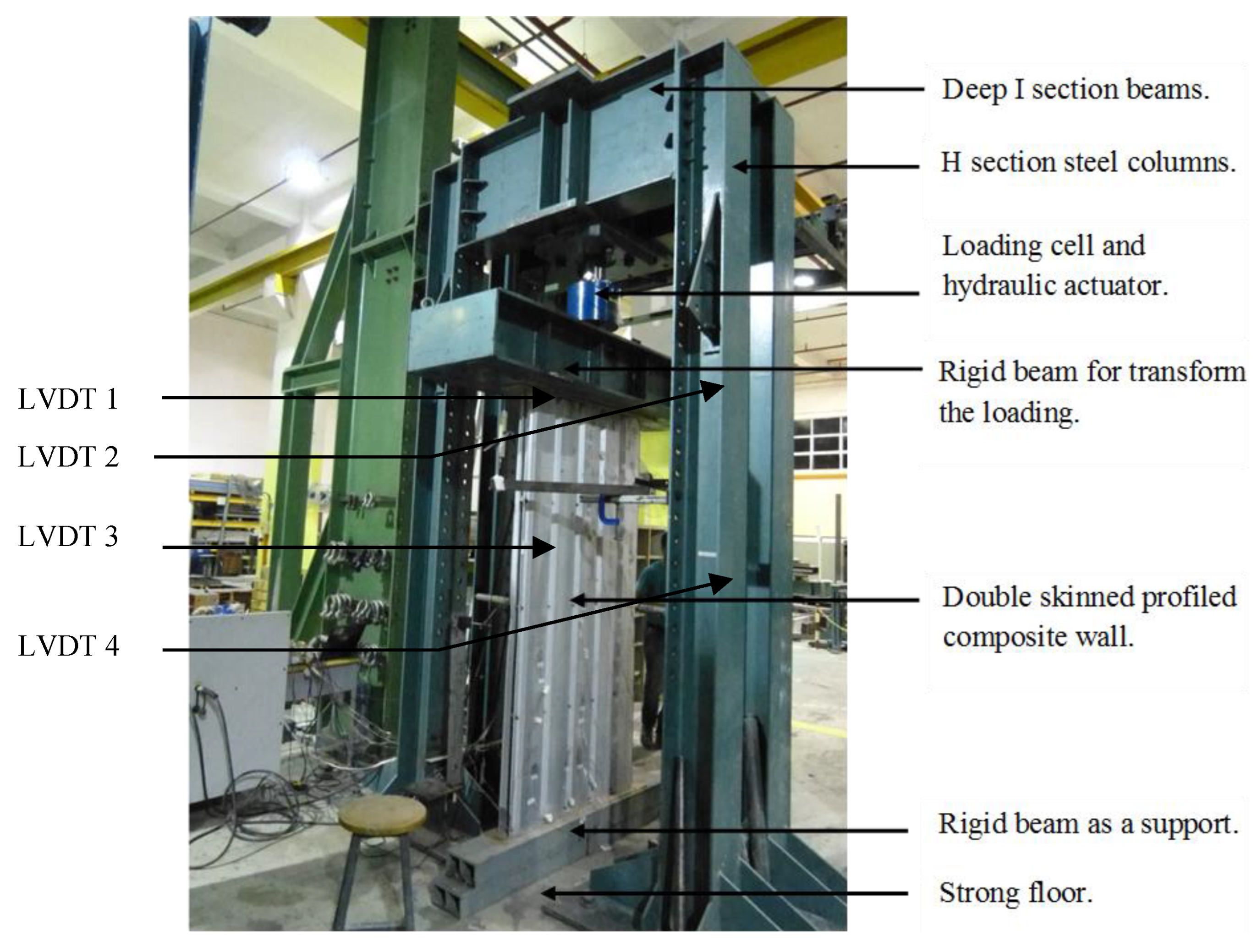
The test setup for the experimental study consisted of two main components: the specimen and the rigid steel frame fabricated from H-section steel columns and two deep I-section beams. A loading actuator, along with a rigid beam, was used to transfer the load to the DSPCW specimens. A schematic representation of the setup is shown in Figure 5. The setup included a loading cell and an ENERPAC hydraulic actuator model RRH6010, capable of applying a maximum compression force of 1800–2000 kN, positioned at the top of the specimens. Displacement measurements were taken using four LVDTs (linear variable differential transducers) of type RDP Electronics ACT500A. Two LVDTs were placed vertically beneath the deep I-section beam (left and right), attached to the loading cell, and two were positioned horizontally on the left and right sides of the specimens to capture the horizontal displacement during the test. These devices were available at the Structural Laboratory of UiTM in Malaysia. The test setup for the experimental study comprised a specimen and a rigid steel frame consisting of H-section steel columns and deep I-section beams. A loading actuator and a rigid beam were used to transfer the load to the DSPCW specimens. The setup included a loading cell and an ENERPAC hydraulic actuator, model RRH6010. Displacement measurements were obtained using four strategically placed LVDTs. These components were available at the Structural Laboratory of UiTM-Malaysia, facilitating the successful execution of the experimental tests.

3. Discussion of the Experimental Results

3.1. Axial Load vs. Displacement Relationship

Both DSPCW specimens underwent axial loading at a displacement rate of 0.5 mm per minute. The first specimen (Oct.) reached its ultimate load (Pu) of 1473 kN with a displacement of 11.0 mm, as shown in Figure 6. Similarly, the second specimen (Ope-Oct.) achieved its ultimate axial load of 1338 kN with a displacement of 11.0 mm. The load-displacement relationship revealed that the presence of the opening resulted in a 9.4% reduction in the ultimate axial load, with specimen Oct. reaching 1473 kN compared to 1338 kN for specimen Ope-Oct., as summarized in Table 1. In addition, the stiffness performance of the tested DSPCW specimens can be estimated from the load-displacement curve presented in Figure 6.

3.2. Failure Modes

To assess the impact of openings on the structural behavior of DSPCWs, the failure modes of the specimens were carefully examined. Specimen (Oct.) exhibited a failure mode characterized by concrete cracking, local buckling on the PSS surfaces, and overall buckling of one of the embedded octagonal CFSTs, as depicted in Figure 7. This observation suggests favorable composite action between the PSS and concrete, while the composite action between the embedded octagonal CFSTs was found to be nearly perfect.
Similarly, specimen (Ope-Oct) displayed a very similar failure mode to that of specimen (Oct.). It showed concrete cracking, local buckling on the PSS surfaces, and overall buckling of one of the embedded octagonal CFSTs, as shown in Figure 8. The ultimate failure mode of the specimen (Ope-Oct) indicates that the presence of openings did not significantly impact the structural behavior of the DSPCWs strengthened with embedded octagonal CFSTs in terms of ultimate failure. However, a slight negative effect on the axial load resistance was observed, as previously demonstrated in the axial load/displacement figures. In conclusion, the experimental results revealed that the presence of openings in DSPCWs slightly reduced the ultimate axial load resistance by 9.4%. However, the failure modes of the specimens (Oct. and Ope-Oct.) remained similar, showing concrete cracking, local buckling on the PSS surfaces, and overall buckling of the embedded octagonal CFSTs. These findings suggest that while openings may have a minor impact on load resistance, the structural behavior of DSPCWs strengthened with embedded octagonal CFSTs remains relatively unaffected.

4. Numerical Approach

To predict the structural behavior of DSPCWs strengthened with embedded octagonal CFSTs under axial loading, a numerical approach was employed using ABAQUS/CAE software. Finite element (FE) models were constructed and analyzed to investigate various factors aimed at mitigating the negative impact of openings on the axial load resistance of the walls [26,27]. The study specifically focused on the effects of altering the cross-sectional shape of the embedded CFSTs and providing support to the embedded CFSTs through the use of different types of stiffeners. By utilizing the ABAQUS/CAE software, the FE models were able to simulate the behavior of the DSPCWs and provide valuable insights into their response under axial loading. The software’s capabilities facilitated the analysis and assessment of different design configurations, allowing for a comprehensive evaluation of the proposed strengthening techniques.

4.1. Description of the FE Model

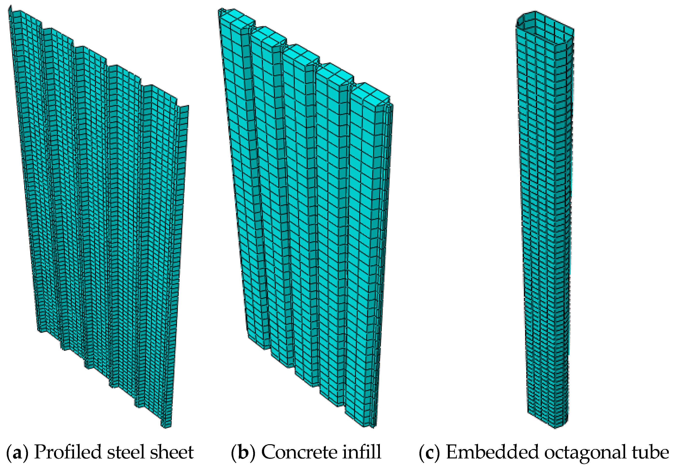
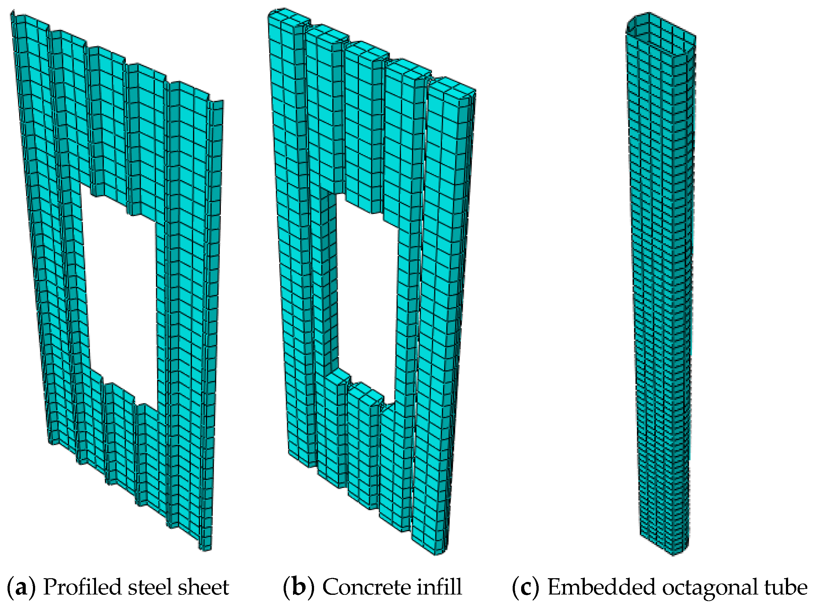
In this study, several finite element (FE) models were developed and analyzed to examine the impact of the cross-sectional shapes of embedded concrete-filled steel tubes (CFSTs) and the effectiveness of supporting these tubes with stiffeners. For the verification study, two FE models were created: one model was strengthened with octagonal CFSTs and labeled as Oct-FE, while the other was designed with openings to match the experimental specimens and labeled as Ope-Oct-FE. Fourteen additional FE models were generated to conduct a parametric study. All FE models in this study had the same material properties, interaction techniques, boundary conditions, and meshing size. The main parts of the DSPCW model without/with an opening are presented in Figure 9 and Figure 10.
Both the Oct-FE and Ope-Oct-FE models consisted of double pre-stressed steel (PSS) members connected with bolts, nuts, and spacers, filled with concrete, and stiffened by embedded octagonal CFSTs. The cold-formed steel sections (PSS and CFST) were modeled as shell elements, while the concrete infill was modeled as solid elements. Homogeneous materials were assumed for both the PSS and concrete infill. These FE models were used as control models for the parametric study.
Various FE models were designed and analyzed to cover the effect of the embedded CFSTs’ cross-sectional shapes and the positive effect of supporting the embedded tubes with stiffeners. Two FE models were generated for the verification study: one was a DSPCW strengthened with embedded octagonal CFSTs labeled as Oct-FE, and the other was designed with an opening labeled as Ope-Oct-FE to match the details of the experimental specimens. Another fourteen FE models were generated to cover the parametric study. All of the FE models in this study were designed with the same material properties, interaction techniques, boundary conditions, and meshing size.
In conclusion, several FE models were developed to examine the impact of the cross-sectional shapes of embedded concrete-filled steel tubes (CFSTs) and the effectiveness of supporting them with stiffeners. Two FE models (Oct-FE and Ope-Oct-FE) were created for the verification study, and an additional fourteen models were generated for a parametric study.

4.2. Elements, Interactions, and Boundary Conditions

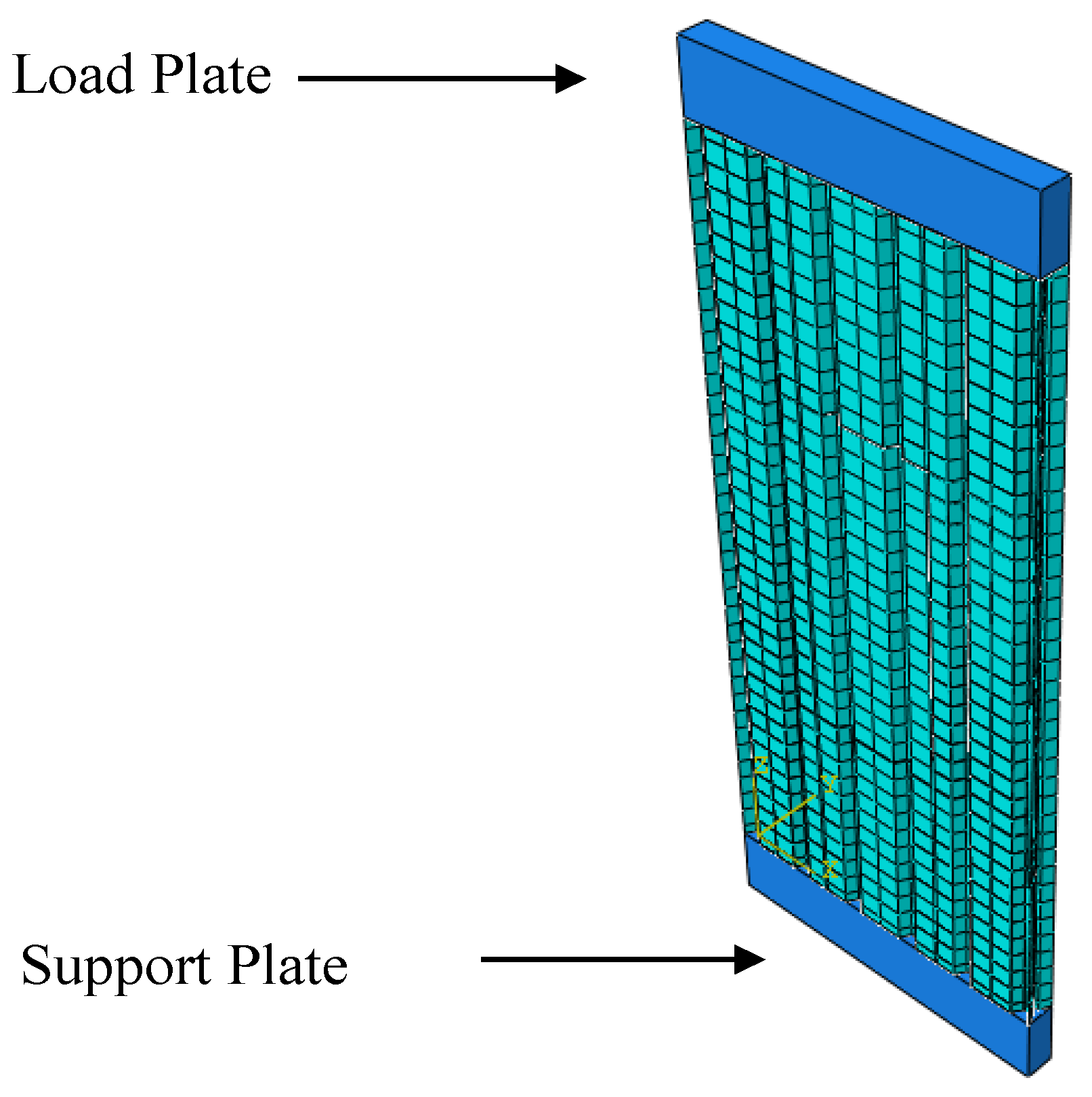
This section discusses the allocation of elements, interactions, and boundary conditions for the FE models. The models were composed of two PSS, embedded CFSTs, concrete infill, and two support plates: one at the top for applying a uniform axial load and the other at the bottom to act as a support, as shown in 
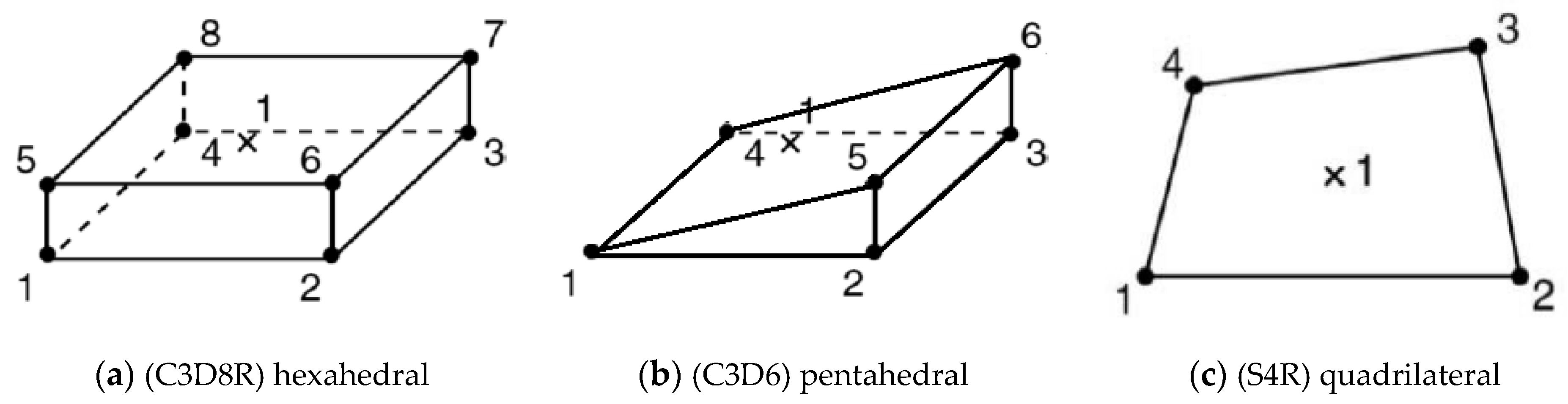
Figure 11. Linear triangular prism (C3D6) elements were utilized for the concrete infill and support plates where automated meshing was insufficient to cover the profiled corners. Linear quadrilateral shell elements (S4R) were assigned to the PSS and the embedded CFSTs. Figure 12 shows the linear elements employed in this study along with their integration points. To account for rough contacting surfaces, various interactions were designated using tangential behavior, with the friction formulation selected and a friction coefficient of 0.5 set. The ‘hard’ contact option was employed for surface interactions of the PSS, embedded CFSTs, and concrete infill. Tie constraints were used to contact the internal surfaces of the embedded CFSTs and concrete infill.
Node tie constraints were employed to link the PSS surfaces together and to the embedded CFST columns, with 30 being used for connecting the PSS surfaces through the concrete and 20 being used to connect them to the embedded CFST. A rigid steel plate was utilized at the bottom of the FE models to act as a support for the wall’s components. The bottom face of the support plate restrained displacements in all three degrees of freedom, and a smooth stepped amplitude function was used to apply a displacement load to the top face of the load plate. Throughout the analysis, no meshing errors were detected, and any warnings were deemed insignificant. Linear triangular prism (C3D6) elements were used for the concrete infill and support plates, while linear quadrilateral shell elements (S4R) were assigned to the PSS and embedded CFSTs. Various interactions were designated using tangential behavior, and tie constraints were employed for contacting surfaces. Node tie constraints were used to link PSS surfaces and embedded CFST columns.

4.3. Modeling of Materials

This study used two materials to simulate the FE models during the numerical analysis stage: cold-formed steel for the PSSs and embedded tubes and normal concrete for the infill material. Concrete Damage Plasticity (CDP) was chosen to simulate the behavior of the concrete material as it was the most recommended option from previous studies [28,29,30,31]. In ABAQUS/CAE, the compressive and tensile behavior of CDP is provided in a tabular function, which requires the input of compressive stress (σo) and elastic strain ( ε c ~ i n ). The data for the compressive stress and strain must be given in absolute (positive) terms and provided in terms of plastic ( ε c p l ), inelastic ( ε c i n ) and elastic strain ( ε c e l ) versus compressive stress. The stress-strain relationship shown in Figure 13 was used to import the tabular data for both the compressive and tensile strengths of the concrete material, which was redesigned based on the same concept given in [32]. The concrete material characteristics were imported from the earlier presented experimental works.
To model the PSS and embedded CFSTs in the FE analysis, the cold-formed steel properties were acquired from tensile coupon tests and represent nominal stress and strain values. However, ABAQUS/CAE uses true stress ( σ t r u e ) and plastic strain ( ε i n p l ) to define cold-formed steel materials in the software. These values can be calculated from the tensile coupon data using two equations given in [33]:
σ t r u e = σ n o m ( 1 + ε n o m )
ε ln p l = ln ( 1 + ε n o m ) σ t r u e E
where σ n o m is the nominal stress, ε n o m is the nominal strain, and E is the modulus of elasticity obtained from the tensile test of the cold-formed steel coupons.
Accordingly, the concrete damage plasticity (CDP) option that is available in the ABAQUS software was used to simulate the behavior of the concrete material. Cold-formed steel properties were acquired from tensile coupon tests, and true stress and plastic strain were used to define the cold-formed steel materials in ABAQUS/CAE.

4.4. Convergence Study

To ensure the accuracy of our finite element (FE) models, a convergence study was conducted to determine the optimal mesh size. The study involved analyzing eight different mesh sizes and comparing their results to assess the convergence of the solution. The objective was to select a mesh size that balanced accuracy and computational efficiency. The ultimate axial load was used as the convergence criterion in this study. Specifically, the models with 35,034 and 61,074 elements were analyzed and compared to evaluate the influence of mesh size on the output. The ultimate loads for these two mesh sizes were determined to be 1512 kN and 1516 kN, respectively, indicating a small percentage difference (see Figure 14).
The comparison between different mesh sizes revealed that the variation in the ultimate axial load was minimal. This indicates that the chosen mesh sizes adequately captured the structural behavior of the DSPCWs strengthened with embedded octagonal CFSTs under axial loading. Additionally, the computational effort required for the 35,034-element mesh was significantly lower than that of the 61,074-element mesh, providing time-saving benefits without compromising the accuracy of the results.
Furthermore, other output parameters such as displacements, stresses, and failure modes were also compared among the different mesh sizes. It was observed that these parameters exhibited similar trends and magnitudes across the various mesh sizes, confirming the consistency and robustness of the selected mesh size. In conclusion, the comparison between different mesh sizes demonstrated that the selected mesh size of 35,034 elements provides accurate results with computational efficiency. The negligible differences in the output parameters between different mesh sizes confirm the adequacy of the chosen mesh size for capturing the behavior of the DSPCWs under investigation.

4.5. Verification Study

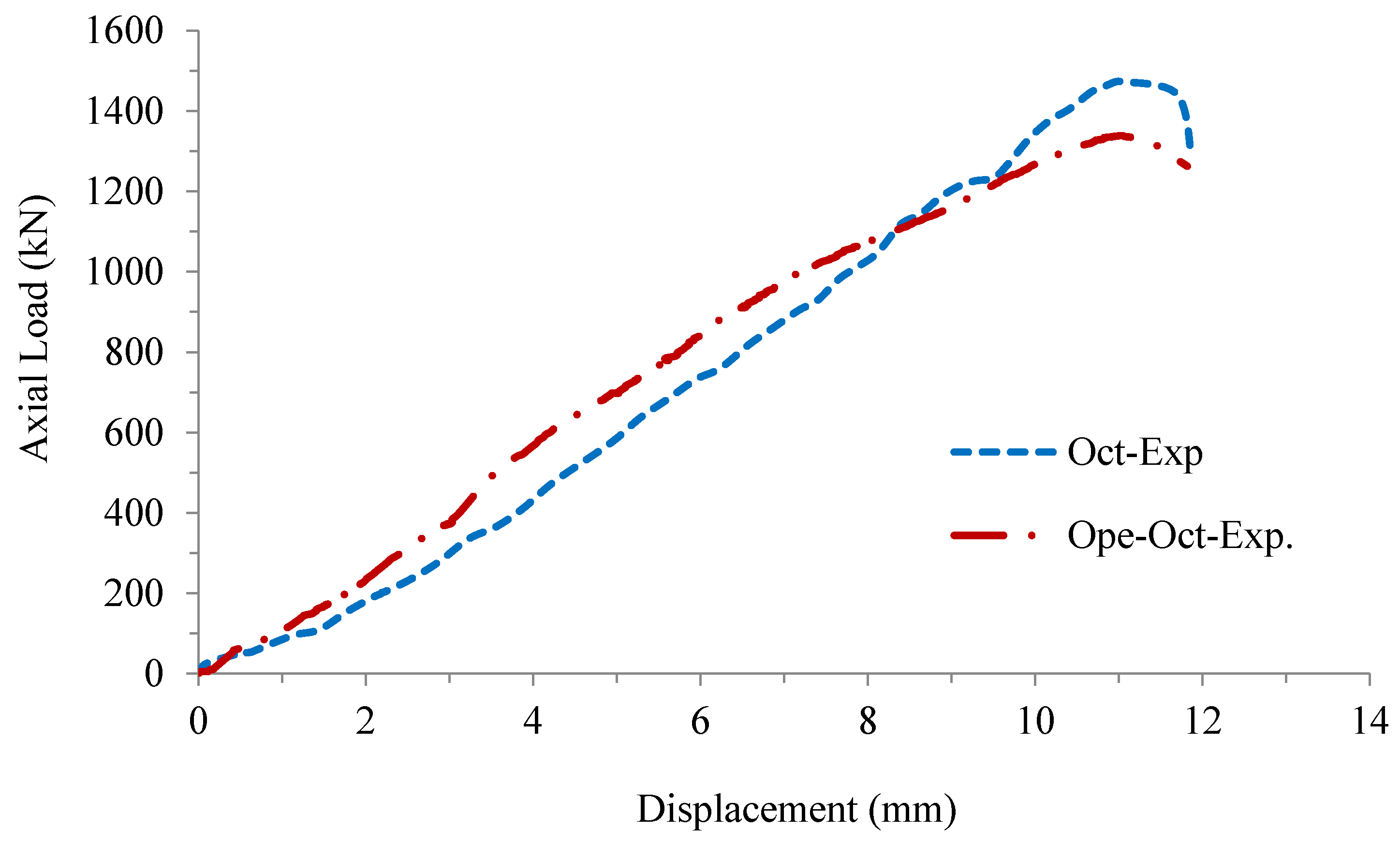
To validate the accuracy of our FE analysis, a comprehensive verification study was conducted by comparing the predicted axial load behavior of DSPCW models with the corresponding experimental results. Two FE models, namely Oct-FE and Ope-Oct-FE, were compared to their experimental counterparts, Oct-Exp and Ope-Oct-Exp, respectively. This comparison involved analyzing the axial load versus displacement responses of the FE models and comparing them to the experimental results.
The results of the verification study demonstrated a high level of accuracy in the FE analysis. The ultimate load values obtained from Oct-FE and Oct-Exp were 1512 kN and 1473 kN, respectively, resulting in a difference percentage of only +2.6% (Figure 15a and Table 2). Similarly, the ultimate load values of Ope-Oct-FE and Ope-Oct-Exp were 1467 kN and 1338 kN, respectively, with a difference percentage of only +12.4% (Figure 15b and Table 2). These findings indicate a close agreement between the numerical predictions and the experimental results. The small differences in percentages demonstrate the high accuracy of our FE models in capturing the axial load behavior of DSPCW systems.
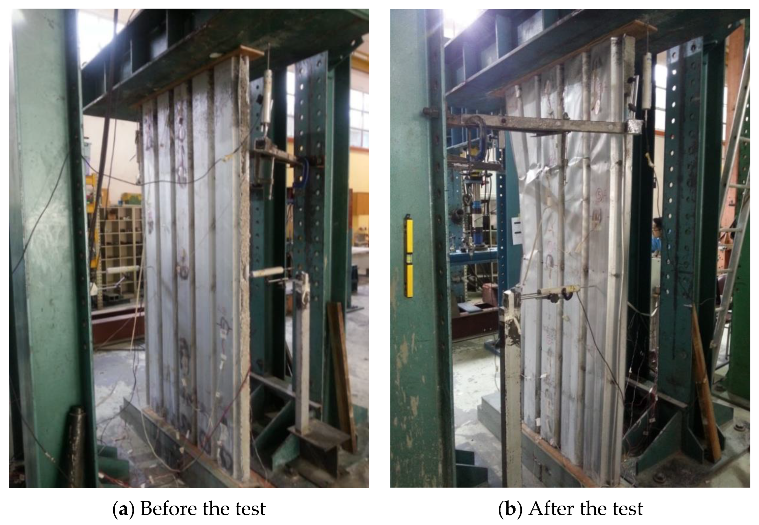
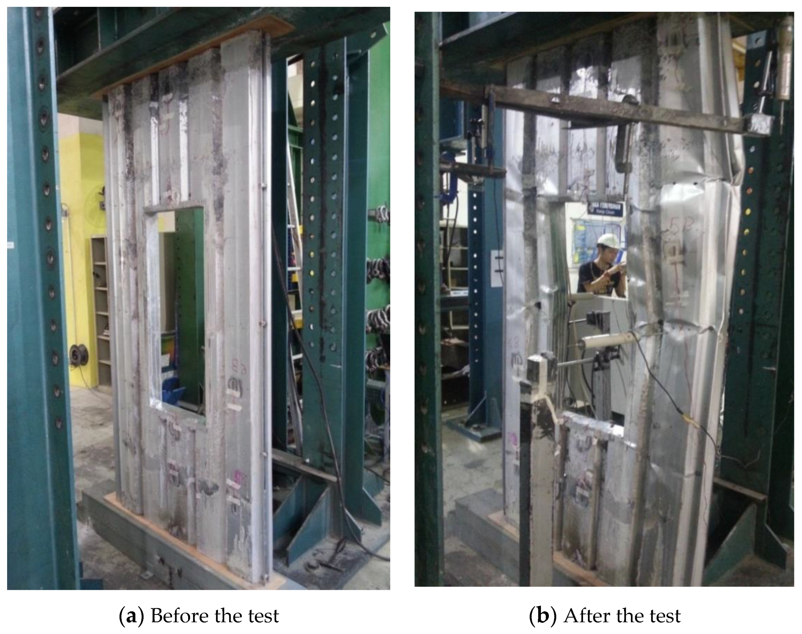
In specimen Oct, the observed failure mode was characterized by concrete cracking, followed by local buckling at the surfaces of the PSS. Subsequently, the overall buckling of one of the embedded octagonal cold-formed steel tubes occurred. Similarly, in specimen Ope-Oct, the failure mode mirrored that of specimen Oct, featuring concrete cracking followed by local buckling at the surfaces of the PSS, ultimately leading to the overall buckling of one of the embedded octagonal cold-formed steel tubes. Figure 16 provides visual confirmation of the failure modes of the DSPCW models under axial static load. However, it is important to highlight that the overall buckling failure shown earlier in Figure 8 occurred at the extreme loading stage and after the tested walls had already reached their ultimate strength capacity. Meanwhile, the analysis of the corresponding FE models was stopped when the models reached their loading capacity. Thus, only the local buckling failure mode of the PSS parts of these FE models was clearly observed (see Figure 16) and accurately simulated the actual local buckling, unlike the global buckling. Based on the above, this study confidently concludes that the suggested FE analysis accurately predicts the axial load behavior of the tested DSPCW specimens. This verification study further strengthens the reliability of the numerical approach in simulating the actual structural behavior of DSPCW systems under pure axial load since the FE models slightly overestimated the wall loading capacity by about +2.6% to +12.4%, compared to the tested specimens Oct. and Ope-Oct., respectively.

5. Parametric Study

A parametric study was conducted to investigate ways to reduce the effect of the opening on the structural behavior of the DSPCW system based on the low standard deviation (+10%) observed in the verification study. Different cross-sectional shapes of the embedded CFSTs were examined, as was the positive effect of supporting the tubes with different stiffeners. These parameters were chosen to meet the objectives of the study, and all the FE results were verified using a theoretical formula developed and presented later in the paper. The Oct-FE and Ope-Oct-FE models were used as control models for the subsequent parametric study.

5.1. Effect of the Embedded Tube’s Cross-Section

In order to investigate the effect of the cross-sectional shapes of the embedded tubes on the axial load resistance of the DSPCW system, three different FE models with different cross-sectional shapes (octagonal, hexagonal, and rectangular) of the embedded CFSTs were designed and analyzed. The models were named Ope-Oct-FE, Ope-Hex-FE, and Ope-Rec-FE, and their cross-sections with a front view were presented in Figure 17.
The study examined the effect of different cross-sectional shapes of the embedded CFSTs on the axial load resistance of the DSPCW system. Three FE models were analyzed, featuring octagonal, hexagonal, and rectangular cross-sections. The results showed that the octagonal cross-section provided the highest axial load resistance, followed by the hexagonal and rectangular shapes. The Ope-Oct-FE model exhibited an ultimate axial load of 1467 kN, while the Ope-Hex-FE and Ope-Rec-FE models had loads of 1320 kN and 1239 kN, respectively. The octagonal cross-section demonstrated the most favorable performance, offering a potential design solution for enhancing the structural behavior of DSPCW systems, as presented in Figure 18 and compared in Table 3. These results showed that the octagonal cross-section of the embedded CFSTs provided the highest axial load resistance, followed by the hexagonal and rectangular cross-sections. Accordingly, the DSPCW model with octagonal CFST columns showed slightly stiffer performance (higher stiffness value) than the models with hexagonal and rectangular CFST columns.

5.2. Effect of the Embedded Octagonal Tubes Stiffened with Steel Stiffeners

To improve the ultimate axial load and ductility of the DSPCW system and reduce the negative effect of the opening on axial load resistance, this study proposes supporting the embedded octagonal CFSTs with stiffeners. Four FE models were designed and analyzed, labeled as Ope-Oct-L, Ope-Oct-T, Ope-Oct-U, and Ope-Oct-V, to represent DSPCWs with openings strengthened with embedded octagonal CFSTs supported with L, T, U, and V stiffeners, respectively. The details of these FE models are presented in Figure 19.
The ultimate axial loads of models Ope-Oct-L, Ope-Oct-T, Ope-Oct-U, and Ope-Oct-V were 1536 kN, 1649 kN, 1620 kN, and 1507 kN, respectively, and the displacements were 15.5 mm, 15.3 mm, 14.7 mm, and 14.7 mm, respectively, as compared in Table 4. These ultimate axial loads were compared with the ultimate axial load of model Ope-Oct-FE (1467 kN), and deviation percentages were calculated to be +4.7%, +12.4%, +10.4%, and +2.7%, respectively. The results show that the embedded octagonal CFSTs supported with L, T, U, and V stiffeners have a positive effect on the ultimate axial load and ductility of the DSPCW system. Model Ope-Oct-T recorded the highest ultimate axial load resistance with a deviation percentage of +12.4% compared to the control model.
Generally, this parametric study confirmed that stiffening the embedded columns of DSPCW models with L, T, U, and V stiffeners improved their ultimate axial load and ductility performance compared to the control model. Among them, model Ope-Oct-T demonstrated the highest increase in ultimate axial load with a deviation percentage of +12.4%. These findings highlight the effectiveness of using stiffeners to enhance the structural performance of the DSPCW system, offering potential solutions to reduce the negative impact of openings and improve overall load-carrying capacity and deformation capacity. Additionally, changing the type of steel stiffener shape showed limited effects on the studied composite wall’s stiffness values, as estimated from the models’ load-displacement curves in Figure 20.

5.3. Effect of the Embedded Hexagon Tubes Stiffened with Steel Stiffeners

To investigate the effect of supporting the embedded hexagonal CFSTs with various stiffeners on the ultimate axial load and ductility of the DSPCW system, four FE models were analyzed. These models were named Ope-Hex, Ope-Hex-L, Ope-Hex-T, Ope-Hex-U, and Ope-Hex-V, representing DSPCWs with openings strengthened with embedded hexagonal CFSTs supported with L, T, U, and V stiffeners, respectively. The details of these FE models were presented in Figure 21.
The ultimate axial loads of models Ope-Hex, Ope-Hex-L, Ope-Hex-T, Ope-Hex-U, and Ope-Hex-V were 1320 kN, 1501 kN, 1545 kN, 1526 kN, and 1438 kN, respectively, and the displacements were 10.7 mm, 13.4 mm, 14.1 mm, 13.9 mm, and 12.9 mm, respectively, as compared in Table 5. The ultimate axial loads were compared with the ultimate axial load of model Ope-Hex (1320 kN), and deviation percentages were calculated. The results showed that the model supported with T stiffeners (Ope-Hex-T) had the highest ultimate axial load with a deviation percentage of +17.0%. The models supported with L, U, and V stiffeners also showed an increase in ultimate axial load with deviation percentages of +13.7%, +15.6%, and +8.9%, respectively.
Figure 22 presents the axial load vs. displacement relationships of DSPCW models with embedded hexagonal CFSTs that have varied steel stiffener shapes. Generally, the investigation of supporting embedded hexagonal CFSTs with various stiffeners in the DSPCW system revealed significant improvements in the ultimate axial load and ductility. The FE models with L, T, U, and V stiffeners demonstrated increased ultimate axial loads compared to the control model, with the T-shaped stiffeners exhibiting the highest enhancement. These findings emphasize the effectiveness of stiffeners in enhancing the system’s performance and mitigating the negative impact of openings on axial load resistance. Incorporating T-shaped stiffeners is recommended to optimize the axial load resistance of the DSPCW system. Additionally, no significant changes were recorded in the stiffness performance of the wall models with hexagonal CFST columns when only the shape of the steel stiffeners changed.

5.4. Effect of the Embedded Rectangular Tubes Stiffened with Steel Stiffeners

In this study, the effect of supporting rectangular embedded CFSTs with different stiffeners on the ultimate axial load of DSPCW with an opening was investigated. Four FE models were analyzed, namely Ope-Rec-L, Ope-Rec-T, Ope-Rec-U, and Ope-Rec-V, which represent DSPCW with an opening and are strengthened with embedded rectangular CFSTs supported with L, T, U, and V stiffener shapes, respectively. The details of these FE models were presented in Figure 23.
The results showed that supporting the embedded rectangular CFSTs with stiffeners can increase the ultimate axial load of the DSPCW system and reduce the negative effect of the opening on the axial load resistance. The ultimate axial loads of models Ope-Rec-L, Ope-Rec-T, Ope-Rec-U, and Ope-Rec-V were 1405 kN, 1477 kN, 1441 kN, and 1345 kN, respectively, which are higher than the value of the control model (without stiffeners; 1239 kN), as compared in Table 6. The displacement values for the four FE models were comparable, with Ope-Rec-T showing the highest displacement of 12.9 mm and Ope-Rec-U and Ope-Rec-V showing the lowest displacement values of 12.5 mm and 12.9 mm, respectively.
Figure 24 compares the load-displacement relationships of the DSPCW models with embedded rectangular CFST columns that were stiffened with varied shapes of steel stiffeners. Generally, the choice of stiffener shape plays a significant role in the system’s ultimate axial load and ductility. These findings emphasize the effectiveness of stiffeners in improving the performance of DSPCW with openings, offering potential solutions for enhancing load resistance in structural applications. Additionally, limited effects were recorded on the stiffness of the strengthened DSPCW models with varied steel stiffeners, as shown by their load-displacement curves in Figure 24.

6. Discussion

The objective of this investigation was to examine the impact of openings on the axial load behavior of DSPCWs strengthened with embedded octagonal CFSTs and to assess the effectiveness of various stiffeners in supporting these CFSTs. A comparison between specimens (Oct.) and (Ope-Oct.) revealed a 10.1% reduction in the ultimate axial load for the specimen with the opening. However, the ultimate failure mode of the specimen with the opening demonstrated that it did not negatively affect the structural behavior of the DSPCWs with embedded octagonal CFSTs.
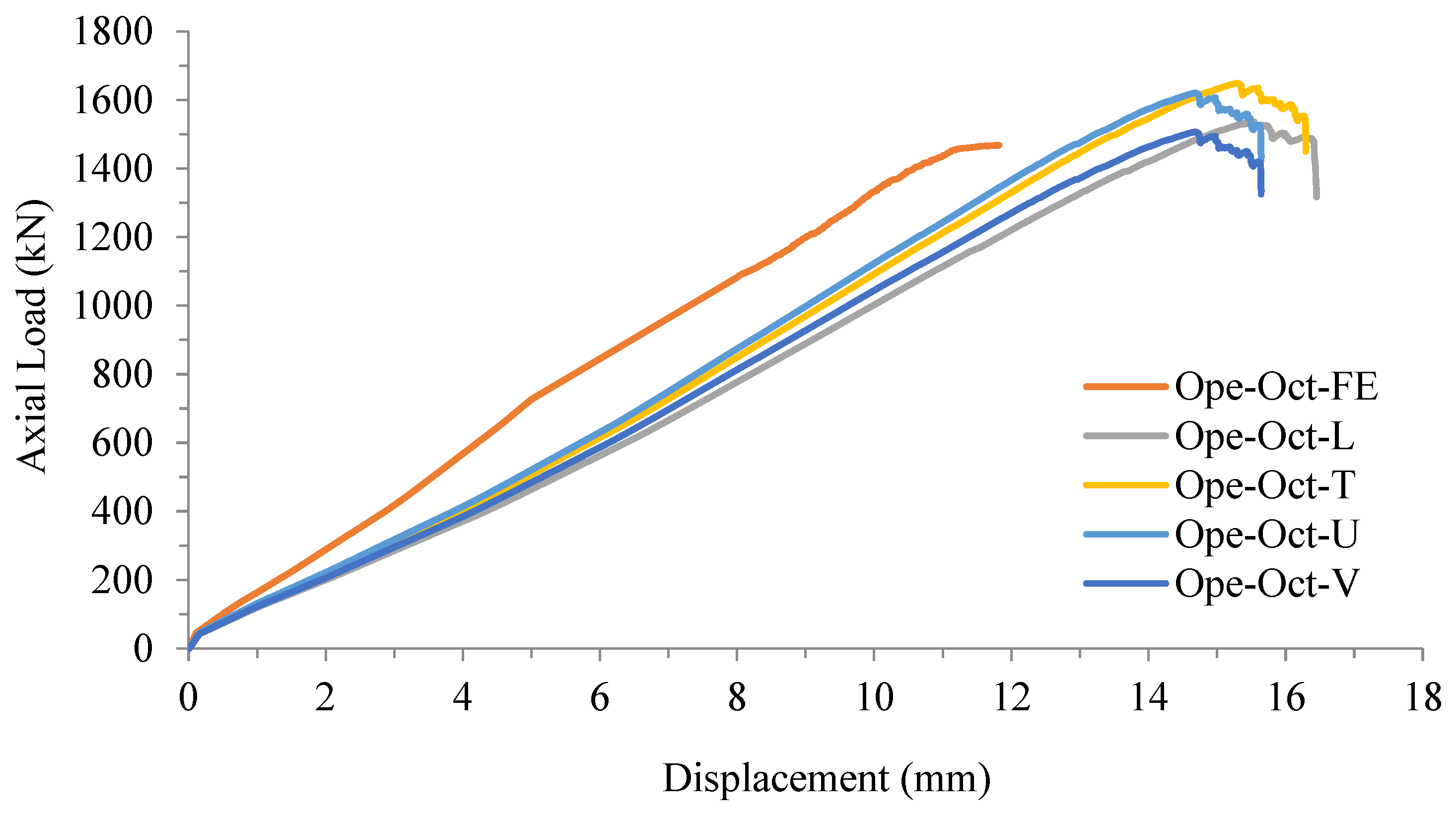
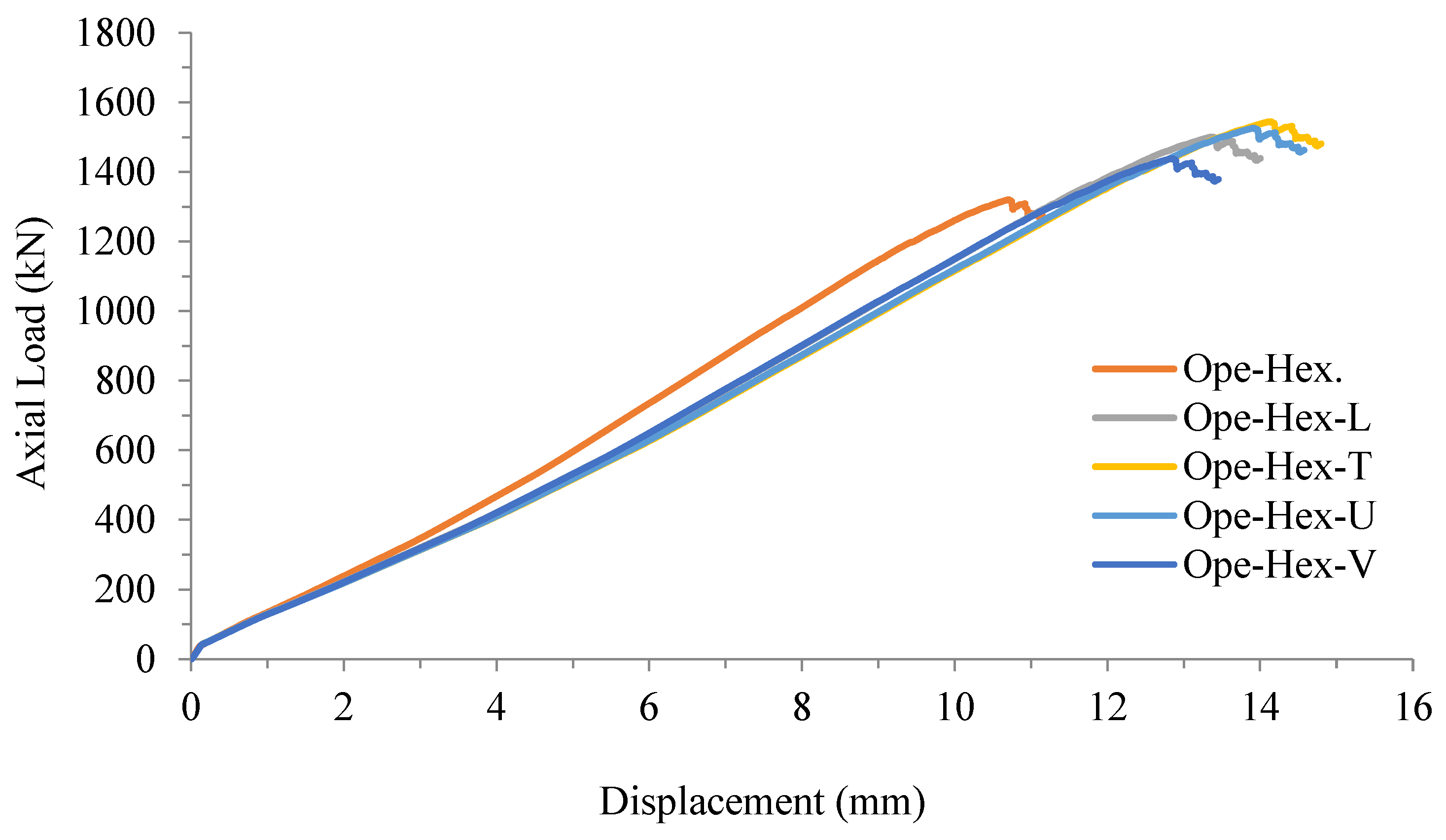
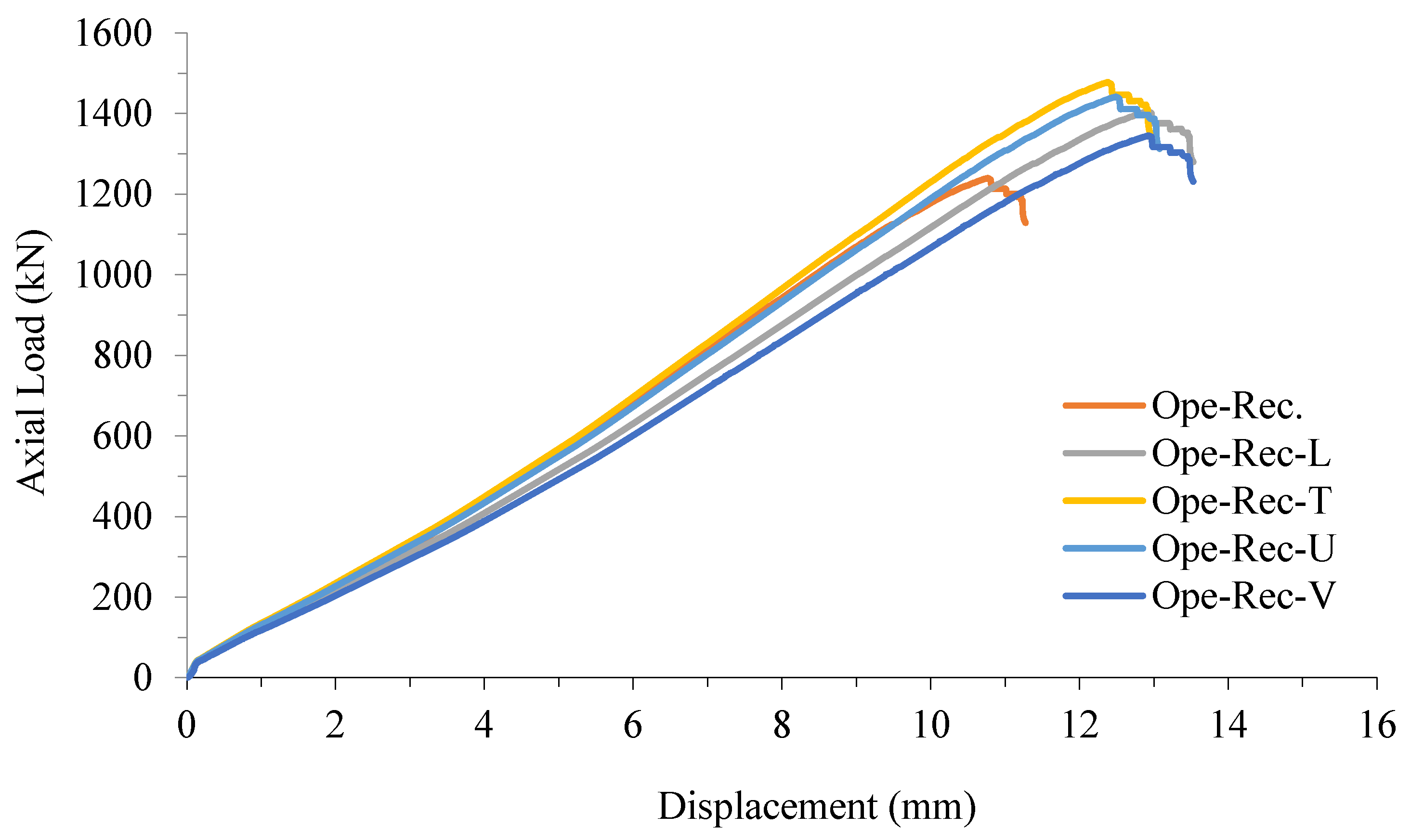
The study found that the octagonal cross-section of the embedded CFSTs outperformed the hexagonal and rectangular shapes in strengthening the DSPCW system with an opening to resist higher axial loads. This can be attributed to the eight angles in the octagonal shape acting as stiffeners, effectively resisting local buckling and enhancing the system’s axial load resistance. In contrast, the hexagonal and rectangular shapes, with fewer angles, exhibited poorer tolerance to axial loads.
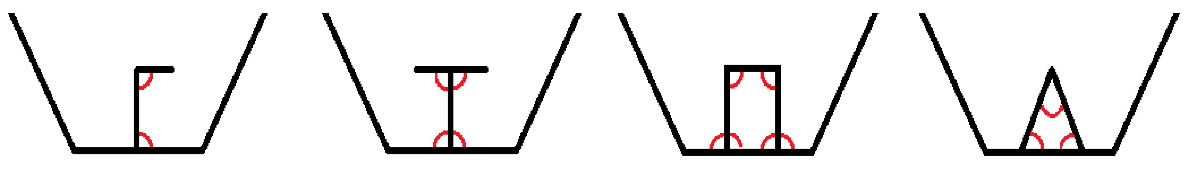
The FE results indicated that supporting the embedded octagonal CFSTs with a T-shaped stiffener proved to be the most effective method for improving the axial load resistance of the DSPCW system. The T-shaped stiffener, when welded to the embedded tubes, generated four angles, delaying local and overall buckling and enabling the system to withstand higher axial loads [32]. While the U-shaped stiffener generated six angles, the model (Ope-Oct-U) exhibited slightly lower axial load resistance than the model (Ope-Oct-T) due to the confinement scenario. The T-shaped stiffener demonstrated superior performance in effectively tying the embedded tube surface to the infilled concrete compared to the U-shaped stiffener. As a result, this study highlights the effectiveness of embedded tubes and stiffeners in enhancing the performance of the DSPCW system, as illustrated in Figure 25. The findings contribute valuable insights into the design and optimization of DSPCW systems and serve as a valuable reference for future research in this area.

7. Conclusions

In this study, we investigated the impact of openings on the axial load behavior of double-skin profiled composite walls (DSPCWs) strengthened with embedded CFST columns. Our findings can be summarized as follows:
  • Firstly, the presence of openings in DSPCWs resulted in a reduction of approximately 10% in their axial capacity compared to control walls without openings. Specifically, the axial load capacity of the control wall was recorded as 1473 kN, while the wall with an opening (Ope-Oct.) had an axial load capacity of 1338 kN.
  • Secondly, the currently adopted numerical approach effectively simulates the experimental results of the ultimate loading capacity and axial behavior of DSPCWs strengthened with embedded CFST columns. The FE models of both walls with and without openings reasonably overestimated the actual results by about 2.6% and 12.4%, respectively. Additionally, unlike the overall buckling failure observed in the tested specimens, which occurred at the extreme loading stage, the corresponding FE models accurately simulated the local buckling failure mode of the PSS parts.
  • Thirdly, among the different cross-sectional shapes of CFST columns, octagonal shapes demonstrated superior performance, achieving an increase in loading capacity of 11% and 18.4% compared to hexagonal and rectangular CFST columns, respectively. For example, the octagonal CFST columns increased the axial load capacity of the DSPCW system to 1642 kN.
  • Additionally, the introduction of internal steel stiffeners to reinforce the embedded CFST columns led to further enhancements in the axial loading capacity of DSPCWs. Specifically, T-shaped stiffeners exhibited superior performance compared to L-shaped, V-shaped, and U-shaped stiffeners, resulting in increased capacity for DSPCWs with openings. For instance, the T-shaped stiffeners increased the axial load capacity of the DSPCW system by 19.2% compared to the control wall without stiffeners.
  • The current study confirms that embedded CFST columns are effective in improving the axial loading capacity of DSPCWs, even in the presence of openings. The choice of CFST column shape and the use of steel stiffeners significantly influence the performance of DSPCWs. Future research is required to explore additional parameters that have not yet been investigated and develop analytical models to accurately predict the axial capacity of the suggested composite wall system. Additionally, efforts should be made to suggest and develop a simplified fabrication process scenario.

Author Contributions

Conceptualization, S.J.H., M.J.H. and A.W.A.Z.; data curation, S.J.H., M.J.H., A.W.A.Z. and M.M.A.; formal analysis, M.M.A. and M.M.F.; funding acquisition, S.J.H., M.J.H., A.B.M.A.K. and A.H.A.-Z.; investigation, S.J.H., M.M.A. and M.M.F.; methodology, S.J.H., M.J.H. and A.W.A.Z.; project administration, M.J.H., A.H.A.-Z. and W.H.W.B.; validation, S.J.H., A.B.M.A.K., M.M.A. and M.M.F.; resources, M.J.H., A.H.A.-Z. and W.H.W.B.; software, S.J.H., A.W.A.Z. and M.M.A.; supervision, A.H.A.-Z., A.W.A.Z. and W.H.W.B.; visualization, S.J.H., A.B.M.A.K. and M.M.F.; writing—original draft, S.J.H., A.W.A.Z., M.M.A., M.M.F. and A.B.M.A.K.; writing—review and editing, M.J.H., A.H.A.-Z. and W.H.W.B. All authors have read and agreed to the published version of the manuscript.

Funding

The authors gratefully acknowledge the financial support for this research provided by the Universiti Kebangsaan Malaysia (UKM) with grant No. (DLP-2014-001).

Institutional Review Board Statement

Not applicable.

Informed Consent Statement

Not applicable.

Data Availability Statement

The data are presented in the article.

Acknowledgments

The authors highly acknowledge their institutes and universities for their support in preparing and completing this research.

Conflicts of Interest

The authors declare no conflict of interest.

Abbreviations

Double skinned profiled composite wall (DSPCW), cold-formed steel tube (CFST), profile steel sheet (PSS), finite element (FE), finite element analysis (FEA), double-skinned composite wall (DSCW), experimental (Exp), octagon (Oct.), hexagon (Hex), rectangular (Rec), opening (Ope), modulus of elasticity for concrete (Ec), modulus of elasticity for steel (Es), concrete cube compressive strength at 28 days (fcu), ultimate load (Pu), yield tensile strength of steel (fy), ultimate bending moment capacity (flexural length (Le), thickness (t), concrete damage plasticity (CDP), compressive stress (σo), inelastic strain ( ε c ~ i n ), plastic strain ( ε c ~ pl ), elastic strain ( ε c ~ el ), logarithmic plastic strain ( ε ln pl ), true stress ( σ true ), nominal stress ( σ n o m ), nominal strain ( ε n o m ).

References

  1. Cassese, P.; Riascos, C.; Rainieri, C.; De Luca, G.; Pavese, A.; Bonati, A. Experimental Study on the in-Plane Response of Cast-in-Situ Reinforced Concrete Sandwich Walls under Combined Vertical and Horizontal Load. Procedia Struct. Integr. 2023, 44, 774–781. [Google Scholar] [CrossRef]
  2. Konstandakopoulou, F.; Tsimirika, M.; Pnevmatikos, N.; Hatzigeorgiou, G.D. Optimization of Reinforced Concrete Retaining Walls Designed according to European Provisions. Infrastructures 2020, 5, 46. [Google Scholar] [CrossRef]
  3. Hilo, S.J.; Wan Badaruzzaman, W.H.; Osman, S.A.; Al Zand, A.W.; Samir, M.; Hasan, Q.A. A State-of-the-Art Review on Double-Skinned Composite Wall Systems. Thin-Walled Struct. 2015, 97, 74–100. [Google Scholar] [CrossRef]
  4. Senthilkumar, R.; Karunakaran, P.; Chandru, U. Progress and Challenges in Double Skin Steel–Concrete Composite Walls: A Review. Innov. Infrastruct. Solut. 2023, 8, 32. [Google Scholar] [CrossRef]
  5. Qin, Y.; Shu, G.P.; Fan, S.G.; Lu, J.Y.; Cao, S.; Han, J.H. Strength of Double Skin Steel-Concrete Composite Walls. Int. J. Steel Struct. 2017, 17, 535–541. [Google Scholar] [CrossRef]
  6. Le, Q.X.; Dao, V.T.N.; Torero, J.L.; Ngo, T.D. Experimental Study into the Behaviour of Profiled Composite Walls under Combined Axial and Thermal Loadings. Eng. Struct. 2020, 210, 110354. [Google Scholar] [CrossRef]
  7. Wright, H.D.; Evans, H.R.; Harding, P.W. The Use of Profiled Steel Sheeting in Floor Construction. J. Constr. Steel Res. 1987, 7, 279–295. [Google Scholar] [CrossRef]
  8. Eltayeb, E.; Ma, X.; Zhuge, Y.; Youssf, O.; Mills, J.E.; Xiao, J.; Singh, A. Structural Performance of Composite Panels Made of Profiled Steel Skins and Foam Rubberised Concrete under Axial Compressive Loads. Eng. Struct. 2020, 211, 110448. [Google Scholar] [CrossRef]
  9. Eltayeb, E.; Ma, X.; Zhuge, Y.; Xiao, J.; Youssf, O. Composite Walls Composed of Profiled Steel Skin and Foam Rubberized Concrete Subjected to Eccentric Compressions. J. Build. Eng. 2022, 46, 103715. [Google Scholar] [CrossRef]
  10. Qiao, W.; Zhang, X.; Xu, Q.; Wang, G. Seismic Performance of Thin-Walled Steel and Concrete Composite Column-Corrugated Steel Shear Wall Structure. J. Constr. Steel Res. 2023, 201, 107745. [Google Scholar] [CrossRef]
  11. Li, W.; Chen, H.; Li, F. Performance of Concrete-Filled Double-Skin Shallow-Corrugated Steel Plate Composite Walls under Compression-Bending Load. J. Constr. Steel Res. 2023, 201, 107701. [Google Scholar] [CrossRef]
  12. Sharda, A.; Manalo, A.; Ferdous, W.; Bai, Y.; Nicol, L.; Mohammed, A.; Benmokrane, B. Flexural Behaviour of Composite Modular Wall Systems under Uniformly Distributed and Concentrated Loads. Compos. Struct. 2023, 303, 116346. [Google Scholar] [CrossRef]
  13. Ali, M.M.; Osman, S.A.; Aw, A.Z.; Yatim, M.Y.M.; Alatshana, F.; Hilo, S.J. Concrete-Filled Twin-Layer Steel-Sheet Cws System: A Systematic Review of the Literature. Lat. Am. J. Solids Struct. 2021, 18, 1–43. [Google Scholar] [CrossRef]
  14. An, G.; Wang, R.; Zhao, H.; Chen, W.; Li, T.; Liu, Y. Response of Axial-Loaded Steel-Concrete Composite Walls under Low-Velocity Impact. J. Constr. Steel Res. 2023, 203, 107829. [Google Scholar] [CrossRef]
  15. Eltayeb, E.; Ma, X.; Zhuge, Y.; Youssf, O.; Mills, J.E.; Xiao, J. Structural Behaviour of Composite Panels Made of Profiled Steel Sheets and Foam Rubberised Concrete under Monotonic and Cyclic Shearing Loads. Thin-Walled Struct. 2020, 151, 106726. [Google Scholar] [CrossRef]
  16. Tong, J.-Z.; Pan, W.-H.; Shen, M.-H. Performance of Double-Skin Composite Walls with Re-Entrant Profiled Faceplates under Eccentric Compression. J. Build. Eng. 2020, 28, 101010. [Google Scholar] [CrossRef]
  17. Yu, C.Q.; Tong, J.Z. Compressive Behavior of Slender Profiled Double-Skin Composite Walls. J. Constr. Steel Res. 2021, 182, 106657. [Google Scholar] [CrossRef]
  18. Tong, J.Z.; Yu, C.Q.; Zhang, L. Sectional Strength and Design of Double-Skin Composite Walls Withre-Entrant Profiled Faceplates. Thin-Walled Struct. 2021, 158, 107196. [Google Scholar] [CrossRef]
  19. Li, W.; Li, F.; Chen, H. Performance of Concrete-Filled Double-Skin Shallow-Corrugated Steel Plate Composite Walls under Axial Compression. J. Constr. Steel Res. 2022, 196, 107374. [Google Scholar] [CrossRef]
  20. Wang, S.; Wang, W.; Xie, S.; Chen, Y. Behavior and Design Method of Double Skin Composite Wall under Axial Compression. J. Build. Eng. 2023, 64, 105554. [Google Scholar] [CrossRef]
  21. Wang, M.Z.; Guo, Y.L.; Zhu, J.S.; Yang, X. Flexural-Torsional Buckling and Design Recommendations of Axially Loaded Concrete-Infilled Double Steel Corrugated-Plate Walls with T-Section. Eng. Struct. 2020, 208, 110345. [Google Scholar] [CrossRef]
  22. Hossain, K.M.A.; Mol, L.K.; Anwar, M.S. Axial Load Behaviour of Pierced Profiled Composite Walls with Strength Enhancement Devices. J. Constr. Steel Res. 2015, 110, 48–64. [Google Scholar] [CrossRef]
  23. Al Zand, A.W.; Wan Badaruzzaman, W.H.; Ali, M.M.; Hasan, Q.A.; Al-Shaikhli, M.S. Flexural Performance of Cold-Formed Square CFST Beams Strengthened with Internal Stiffeners. Steel Compos. Struct. 2020, 34, 123–139. [Google Scholar] [CrossRef]
  24. Bahrami, A.; Badaruzzaman, W.H.W.; Osman, S.A. Nonlinear Analysis of Concrete-Filled Steel Composite Columns Subjected to Axial Loading. Struct. Eng. Mech. 2011, 39, 383–398. [Google Scholar] [CrossRef]
  25. ASTM-E8/E8M; Standard Test Methods for Tension Testing of Metallic Materials. ASTM: West Conshohocken, PA, USA, 2009.
  26. Zhang, M.; Ding, J.; Pang, L.; Ding, K. Numerical Study on the Influence of In-Plane Damage on the out-of-Plane Seismic Performance of Masonry Infill Walls with Opening in Reinforced Concrete Frames. Adv. Struct. Eng. 2023, 26, 344–359. [Google Scholar] [CrossRef]
  27. Wen, C.B.; Guo, Y.L.; Sun, H.J.; Tian, Z.H.; He, X. Experimental and Numerical Study on Seismic Performance of Concrete-Infilled Double Steel Corrugated-Plate Walls. J. Build. Eng. 2023, 68, 106171. [Google Scholar] [CrossRef]
  28. Le Minh, H.; Khatir, S.; Abdel Wahab, M.; Cuong-Le, T. A Concrete Damage Plasticity Model for Predicting the Effects of Compressive High-Strength Concrete under Static and Dynamic Loads. J. Build. Eng. 2021, 44, 103239. [Google Scholar] [CrossRef]
  29. Cuong-Le, T.; Minh, H.L.; Sang-To, T. A Nonlinear Concrete Damaged Plasticity Model for Simulation Reinforced Concrete Structures Using ABAQUS. Frat. Ed Integrità Strutt. 2022, 16, 232–242. [Google Scholar] [CrossRef]
  30. Abdualrahman, S.Q.; Al-Zuhairi, A.H. A Comparative Study of the Performance of Slender Reinforced Concrete Columns with Different Cross-Sectional Shapes. Fibers 2020, 8, 35. [Google Scholar] [CrossRef]
  31. Al-Zuhairi, A.H.; Al-Ahmed, A.H.; Abdulhameed, A.A.; Hanoon, A.N. Calibration of a New Concrete Damage Plasticity Theoretical Model Based on Experimental Parameters. Civ. Eng. J. 2022, 8, 225–237. [Google Scholar] [CrossRef]
  32. Hilo, S.J.; Sabih, S.M.; Faris, M.M.; Al-Zand, A.W. Numerical Investigation on the Axial Load Behaviour of Polygonal Steel Tube Columns. Int. Rev. Civ. Eng. 2022, 13, 397. [Google Scholar] [CrossRef]
  33. Wang, M.Z.; Guo, Y.L.; Yang, X.; Zhu, J.S. Compressive Buckling Behaviour of Steel Corrugated-Plates in Contact with a Rigid Medium. Compos. Struct. 2021, 262, 113356. [Google Scholar] [CrossRef]
Figure 1. Details of the steel parts (all dimensions in mm).
Buildings 13 01499 g001
Figure 2. Typical details of the DSPCW specimens (all dimensions in mm).
Buildings 13 01499 g002
Figure 3. 3D view of the double-skinned profiled composite wall (DSPCW).
Buildings 13 01499 g003
Figure 4. Stress-strain relationships of the tested steel coupons.
Buildings 13 01499 g004
Figure 5. DSPCW specimen test setup.
Buildings 13 01499 g005
Figure 6. Axial load vs. displacement relationship of the tested DSPCW specimens.
Buildings 13 01499 g006
Figure 7. Failure mode of the DSPCW specimen (Oct).
Buildings 13 01499 g007
Figure 8. Failure mode of the DSPCW specimen with an opening (Ope-Oct).
Buildings 13 01499 g008
Figure 9. Main parts of the DSPCW model (Oct-FE).
Buildings 13 01499 g009
Figure 10. Main parts of the DSPCW model with opening (Ope-Oct-FE).
Buildings 13 01499 g010
Figure 11. DSPCW model’s boundary conditions.
Buildings 13 01499 g011
Figure 12. Element types with the integration points.
Buildings 13 01499 g012
Figure 13. Concrete under uniaxial loading.
Buildings 13 01499 g013
Figure 14. Convergence study for selecting the sufficient mesh size of the wall’s model Oct-FE.
Buildings 13 01499 g014
Figure 15. Verifying the load-displacement relationships of FE models with the experimental specimens.
Buildings 13 01499 g015
Figure 16. Verifying the failure mode of the DSPCW models under axial loading.
Buildings 13 01499 g016
Figure 17. The DSPCW FE models with varied embedded CFST sections.
Buildings 13 01499 g017aBuildings 13 01499 g017b
Figure 18. The load-displacement relationship for DSPCWs strengthened with embedded tubes.
Buildings 13 01499 g018
Figure 19. Cross-sections of DSPCW models with embedded octagonal CFST columns (all dimensions are in mm).
Buildings 13 01499 g019
Figure 20. Load-displacement relationship of DSPCWs with embedded octagonal CFST columns.
Buildings 13 01499 g020
Figure 21. Cross-sections of DSPCW models with embedded hexagonal CFST columns (all dimensions are in mm).
Buildings 13 01499 g021
Figure 22. Load-displacement relationship of DSPCWs with embedded hexagonal CFST columns.
Buildings 13 01499 g022
Figure 23. Cross-sections of DSPCW models with embedded rectangular CFST columns (all dimensions are in mm).
Buildings 13 01499 g023aBuildings 13 01499 g023b
Figure 24. Load-displacement relationship of DSPCWs with embedded rectangular CFST columns.
Buildings 13 01499 g024
Figure 25. Number of angles for each stiffener shape.
Buildings 13 01499 g025
Table 1. Ultimate axial load of the tested DSPCW specimens.
SpecimensUltimate Axial
Load (Pu)
(kN)
Displacement
at Ultimate Load
(mm)
Load Capacity
Reduction
(%)
Oct147311-
Ope-Oct133811−9.4
Table 2. Comparison of the ultimate axial load of FE models with experimental results.
ModelUltimate Axial Load (PExp.) kNUltimate Axial Load
(PFE) kN
PFE/PExp
Oct-FE147315120.974
Ope-Oct-FE133814670.912
Table 3. Compare the results of DSPCW models with varied embedded CFST sections.
ModelsCross-Sectional Shape of TubeAxial Load
(kN)
Displacement
(mm)
Load Deviation
(%)
Ope-Oct-FEOctagonal146711.0-
Ope-Hex-FEHexagonal132010.7−11.0
Ope-Rec-FERectangular123910.8−18.4
Table 4. Results of DSPCW models strengthening octagonal CFSTs with stiffeners.
ModelsStiffeners ShapeLoad
(kN)
Displacement
(mm)
Load Deviation
(%)
Ope-Oct-FE-146711.0-
Ope-Oct-LL153615.5+4.7
Ope-Oct-TT164915.3+12.4
Ope-Oct-UU162014.7+10.4
Ope-Oct-VV150714.7+2.7
Table 5. Results of DSPCW models strengthening hexagonal CFST with stiffeners.
ModelsStiffeners
Shape
Load
(kN)
Displacement
(mm)
Load Deviation
(%)
Ope-Hex.-132010.7-
Ope-Hex-LL150113.4+13.7
Ope-Hex-TT154514.1+17.0
Ope-Hex-UU152613.9+15.6
Ope-Hex-VV143812.9+8.9
Table 6. Results of DSPCW models strengthening rectangular CFST with stiffeners.
ModelsStiffeners
Shape
Load
(kN)
Displacement
(mm)
Load Deviation
(%)
Ope-Rec.-123910.8-
Ope-Rec-LL140512.9+13.4
Ope-Rec-TT147712.4+19.2
Ope-Rec-UU144112.5+16.3
Ope-Rec-VV134512.9+8.6
Disclaimer/Publisher’s Note: The statements, opinions and data contained in all publications are solely those of the individual author(s) and contributor(s) and not of MDPI and/or the editor(s). MDPI and/or the editor(s) disclaim responsibility for any injury to people or property resulting from any ideas, methods, instructions or products referred to in the content.

