1. Introduction
If the upper layers of the subsoil are not sufficiently rigid for the foundation of building structures, shallow slab foundations cannot be used [
1,
2,
3,
4] and in such cases, it is necessary to use deep foundations. One of the most widely used types of deep foundations is the pile foundation. The main function of deep pile foundations is to transfer the vertical load from the upper structure to the subsoil.
A pile is a structural foundation element that carries loads via (i) the bearing capacity at the toe of the pile, (ii) the frictional bearing capacity on the pile casing, or (iii) a combination of both bearing capacities. In the theoretical solution of piles, we distinguish between floating piles and supported piles. In the case of supported piles, we can discuss a hinged or woven support of the pile heel. The support is completely or substantially embedded in soil or rock. Embedding is achieved by (i) driving the finished pile, (ii) making the pile in situ in the excavated hole, or (iii) other technological processes, e.g., screwing or vibrating.
Reinforced columns (i.e., reinforced concrete piles) are the most widely used type of pile in some countries. Two types of piles can be distinguished: solid reinforced concrete piles and hollow piles. These pile types are used up to a length of 60 m. Reinforcement of the piles is achieved using longitudinal members with a diameter of 15 to 24 mm. The minimum reinforcement of piles greater than 10 m in length is 0.8% of the cross-sectional area, and the spacing of the stirrups must not exceed 120 mm. The cover of the reinforcement should range from 25 to 30 mm and be up to 50 mm in harsh environments.
In addition to vertical loads, any structure will induce horizontal effects on foundation elements. Horizontal loads can be caused by wind, ground stress, earthquake forces, wave forces (river or sea), or mooring in seaports. In many current practical studies, the loads are analysed independently first by subjecting the vertical loads to an analysis to determine the bearing capacity and redesign of the pile. Then, the lateral loads are analysed to determine the bending behaviour of the pile [
5]. Thus, in addition to vertical loads, piles are often subjected to lateral loads and bending moments and examples include structures in harbours where lateral forces are caused by the impact of moored ships, or the pull from mooring lines. The p-y method is also used for the solution of laterally loaded piles [
6,
7,
8]. Examples of secondary forces in a harbour include wind pressure, water currents, waves, floating ice pressure, seismic forces, active earth pressure, and differential pressure for different water levels. In addition, the dead weight of the structure and the payload must be considered (Poulos and Davis [
9]). Lateral loads are significantly higher than vertical loads in harbour structures. In some cases, the interaction effects of vertical and lateral loads are necessary for system analysis and their combination is essential.
The analysis and design of pile structures are based on the basic principles of mechanics. The design of a pile under vertical loading is based on the solution of the equilibrium equations in the direction of the vertical force. In cases with lateral pressures, the problem is solved using differential equations. Investigating the ultimate bearing capacity of a vertical pile under lateral load and displacement of the pile head due to the complexity of the interaction between the rigid concrete pile and the elastoplastic soil is a very challenging problem in geotechnical science [
9,
10,
11].
Axial loads only cause displacements parallel to the pile axis. While lateral loads can cause displacement in any direction, the pile-soil system under the influence of lateral loads becomes a 3D problem. In such cases, there is an urgent need to understand the behaviour of the pile under lateral loading. This requires a thorough investigation: researchers have discussed at length the need for an accurate understanding of the behaviour of piles under lateral loads. Extensive research has been conducted in this area, which has been supported by a number of experimental measurements. Among the work from the last time period, we can include the studies [
12,
13,
14], where the authors address the latest knowledge in the field of pile solutions. This paper attempts to highlight the modelling of the contact between the pile and the subgrade. For this mutual contact, special contact elements have been used in FEM. One of the main priorities of this work was to demonstrate the complex analytical solutions of the past years. The obtained analytical results were compared with the numerical solution using FEM, aiming to demonstrate the agreement of the results of the analytical and numerical solutions of a pile stressed by bending. The second objective was to demonstrate the differences in the results obtained with different modelling of the contact between the concrete pile and the ground massif.
2. Bending of Piles—Theoretical Solution
In most cases, bending-stressed piles are investigated as elastic members, co-acting with a flexible and homogeneous, or along-the-length-of-the-pile, variable Winkler-type subgrade. This model describes the behaviour of piles in cohesionless soils reasonably well but does not allow for load distribution in the soil mass. In an attempt to remedy the shortcomings of the Winkler and Pasternak models, and to investigate piles in a uniform manner, the elastic half-space model was introduced. There are generally two approaches: (i) the subsoil is considered as an elastic and homogeneous environment and the pile–subsoil interaction is based on Mindlin’s formulae, or (ii) an inhomogeneous subsoil model is used, and the role of pile–subsoil contact is investigated using the finite element method. In both cases, the analysis is conducted using discrete methods.
The analytical solution is the hybrid force-deformation method presented by B.N. Zemochkin or H. Grasshoff [
10]. It describes how to model the continuous contact stress at the pile–subgrade interface. Significant contributions to analytical solutions of the problem may be found in the work of D.J. Douglas and E.H. Davis [
11], W.R. Spiller and R.D. Stoll [
15], and H.G. Poulos [
16] and S. Prakash [
17], respectively.
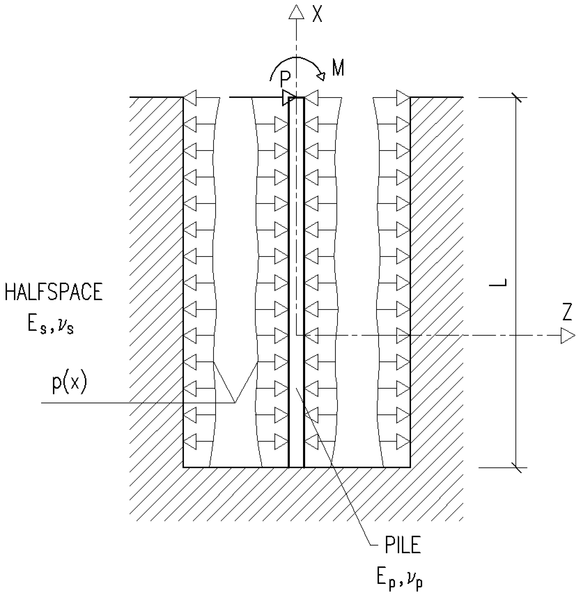
Consider a pile of constant bending stiffness,
EI, of finite length,
L, elastically embedded in a half-space (
Figure 1). We assume that the pile is loaded only at the head by a horizontal force,
P, and an external moment,
M. Under the effect of the load, the pile is reshaped. Unknown contact stresses,
p(
x), are generated at the contact between the pile and the substrate. The problem is to find these contact stresses.
The transverse dimensions of the pile h and b with respect to its length L satisfy the inequality L ≥ 5h or L ≥ 5b. There is no change in the transverse dimensions of the pile during bending.
If we consider that the stress distribution,
p(
x), is along the entire length, then the differential equation holds for the bending of the pile (beam):
where
The first assumption is that the pile deflection
w(
x) and the horizontal displacement of the elastic half-space,
uz (
x), are equal:
where
uz(
x) is the displacement of the half-space points along the pile axis in the axial direction from the contact stresses,
p(
x).
In an elastic half-space, for the displacement,
uz(
x), the following equation holds:
where
p(
b,
c) is the contact stress across the width of pile
b and section
c and
K is the Mindlin solution given by Equation (4):
where:
When the contact stress function, p(x), is known, the pile (beam) differential Equation (1) must be solved to determine the deflection of the pile and the internal forces in the pile.
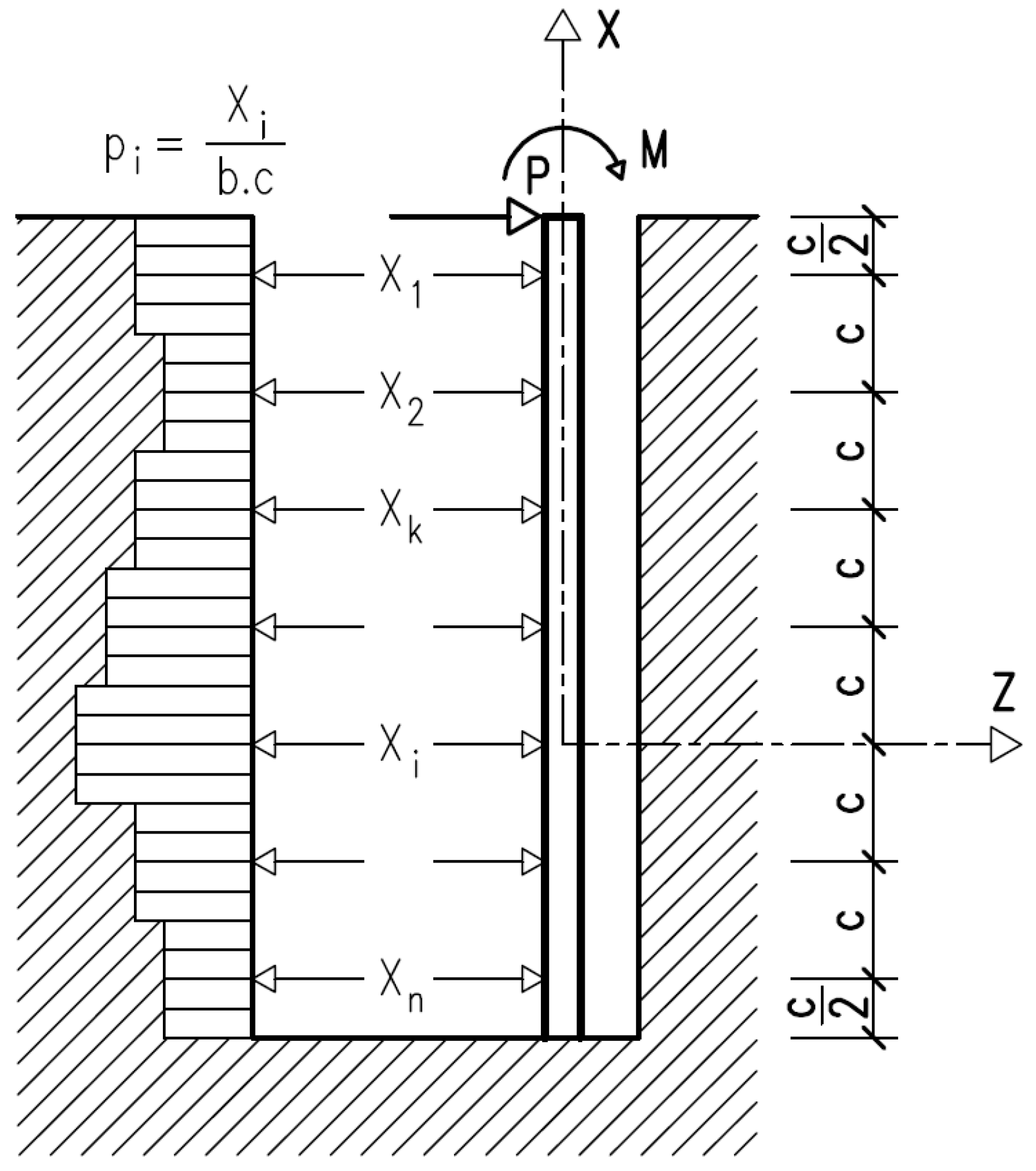
The direct solution of the relations described above in analytical form is very complicated. A discrete method is used, which leads to the solution of the force–deformation equations. The unknown forces are the contact stresses at each interval,
c, and from the method of displacements, we arrive at two equations for the equilibrium of forces and moments from which we solve for the initial values at the pile head: horizontal displacement and rotation. The solution of the basic integral–differential system (1) to (3) proceeds to the solution of a system of algebraic equations. The contact stresses at each section
c are unknown (
Figure 2). We assume a constant stress level,
p, on a given section
c.
Based on this theory, the above relationships were programmed in the 1980s and 1990s. The program was written in Fortran. The results are reported in various papers such as [
18]. The results of solving the bending-stressed piles using the above-mentioned method are compared to the solution of the given problem using FEM, which is the subject of the following chapter.
3. Analysis by FEM
The development of computer technology resulted in a transition from analytical to numerical solutions. Therefore, numerical finite element methods (FEMs) are also emerging in this field of pile solutions in interactions with the subgrade. Here, the internal forces and pile redesign are obtained from large systems of equations. In addition, with the advent of latest-generation computers, it is possible to investigate the effects using three-dimensional finite element analysis (FEA). Programs such as Plaxis for subgrade, or Athena for the solution of reinforced concrete structures are available. Detailed findings are presented in the literature [
5,
19,
20,
21,
22,
23]. Abbas et al. (2008) modelled a single pile in a layered soil using PLAXIS 3D (software based on FEMs), where they compared the lateral bearing capacities of a circular and a square pile.
In solving the problem presented in this paper, we used the ANSYS multifunctional software (version 2021 R2), using the relevant finite element types from the program library. One of the important tasks in modelling structures using FEA is to model the contact between the concrete structure and the subgrade. The contact modelling is discussed in the next section.
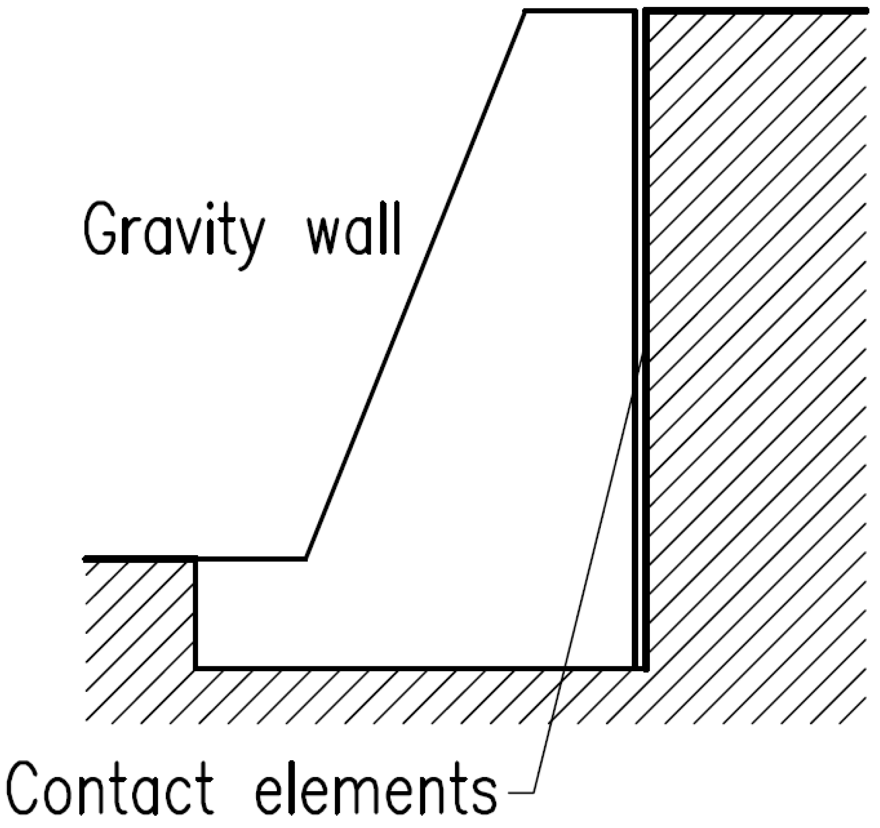
Contact elements are used to model the contact between the pile and the subgrade. They are mainly introduced in calculations where the interaction between the structure and the surrounding environment has to be taken into account and are also suitable for modelling discontinuities or interfaces between two quite different materials (
Figure 3). A typical example of the use of contact elements is in the modelling of retaining structures, retaining walls, or tunnel lining where the contact element is used to simulate a thin region of soil or rock in which intense stresses (predominantly shear) occur.
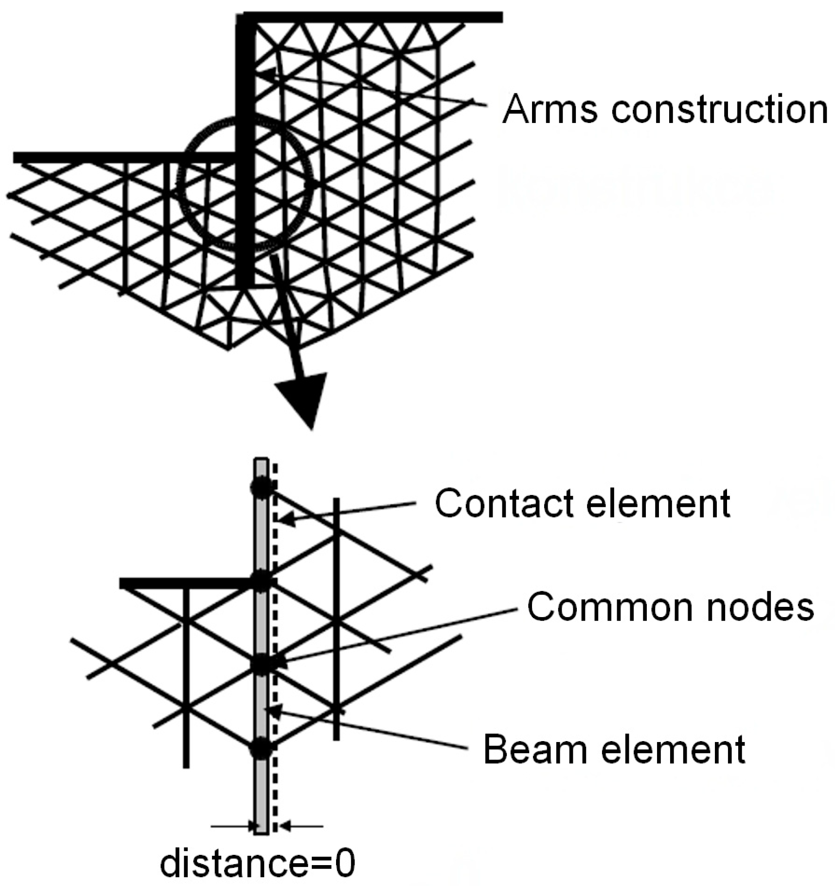
The solution of the contact problems between the foundation structure and the soil mass was encountered in [
24,
25,
26,
27]. A contact element is an element with zero thickness (
Figure 4); it expresses the relationship between contact stresses and the relative change in displacements along the contact.
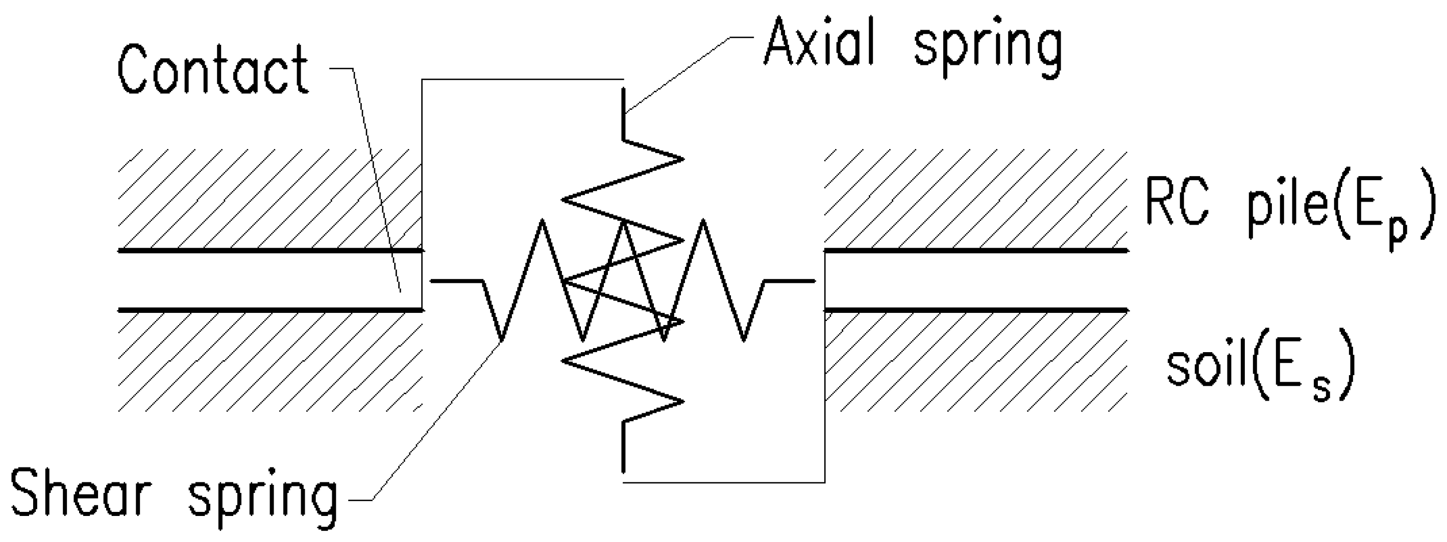
The basic parameters of the contact model are the cohesion,
c; friction coefficient, μ; and dilatancy angle,
Ψ. Other parameters of the contact model are the normal stiffness,
kn, and shear stiffness,
ks. Each stiffness is per unit length of the contact element. These quantities may be thought of as the stiffness of the springs at a given interface, according to
Figure 5. The appropriate choice of these parameters is not straightforward. Some guidance in the choice of the values of the stiffnesses
kn and
ks may be found by relating these parameters to the material characteristics of the soil in contact with the concrete. If the same material is present on both sides of the contact, the following relationships can be used:
where
E is the elastic modulus of the material,
G is the shear modulus of the material, and
t is the contact length. In the case of different materials (for soil,
Es and
Gs; for a reinforced concrete pile,
Ep and
Gp), the smaller of
kn and
ks is considered.
Although the choice of the parameters kn and ks is not essential in the case of plastic contact behaviour, the magnitude of these quantities is crucial for the successful solution of the considered nonlinear problem. Excessive stiffness values (>100,000 kNm−3) can lead to oscillations of the numerical solution. Conversely, low values (<10,000 kNm−3) lead to unrealistic deformations of the structures.
Three different types of contacts can be modelled in ANSYS:
- -
Point-to-point;
- -
Point-to-area;
- -
Area-to-area.
We use two types of model to solve the pile-subgrade contact problem:
- -
Point-to-point contact using the CONTA52 finite element;
- -
Area-to-area contact.
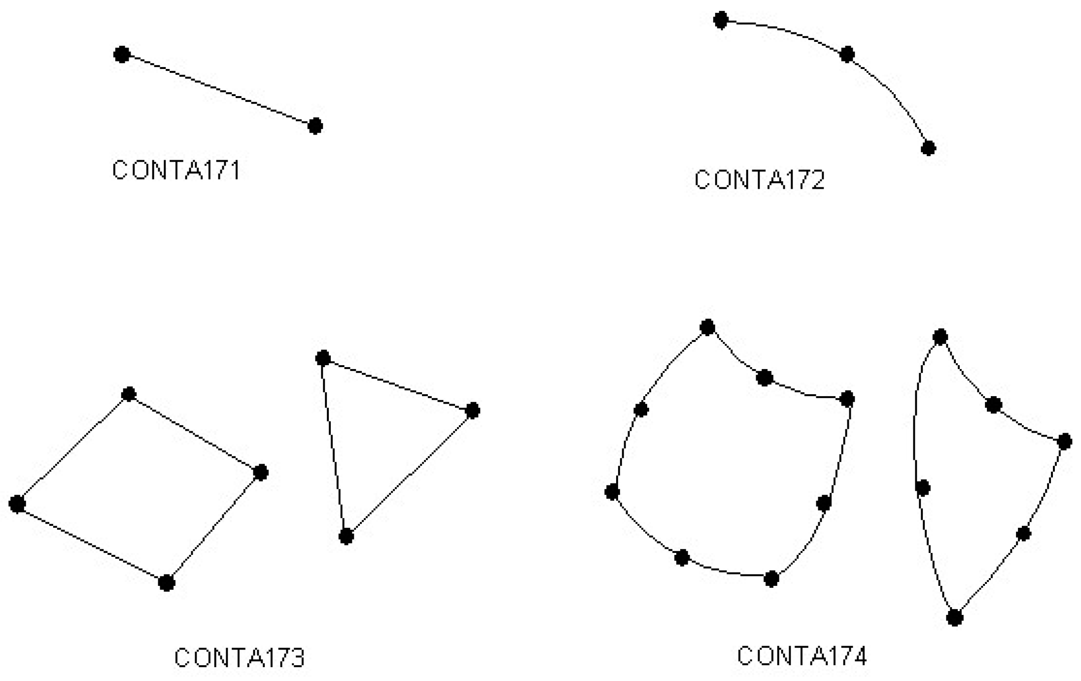
The contacts are defined by a target area and a contact area:
- -
The target area is modelled using TARGE169 elements (for a 2D element);
- -
The contact area is modelled using CONTA171, CONTA172, CONTA173, or CONTA174 elements see the
Figure 6.
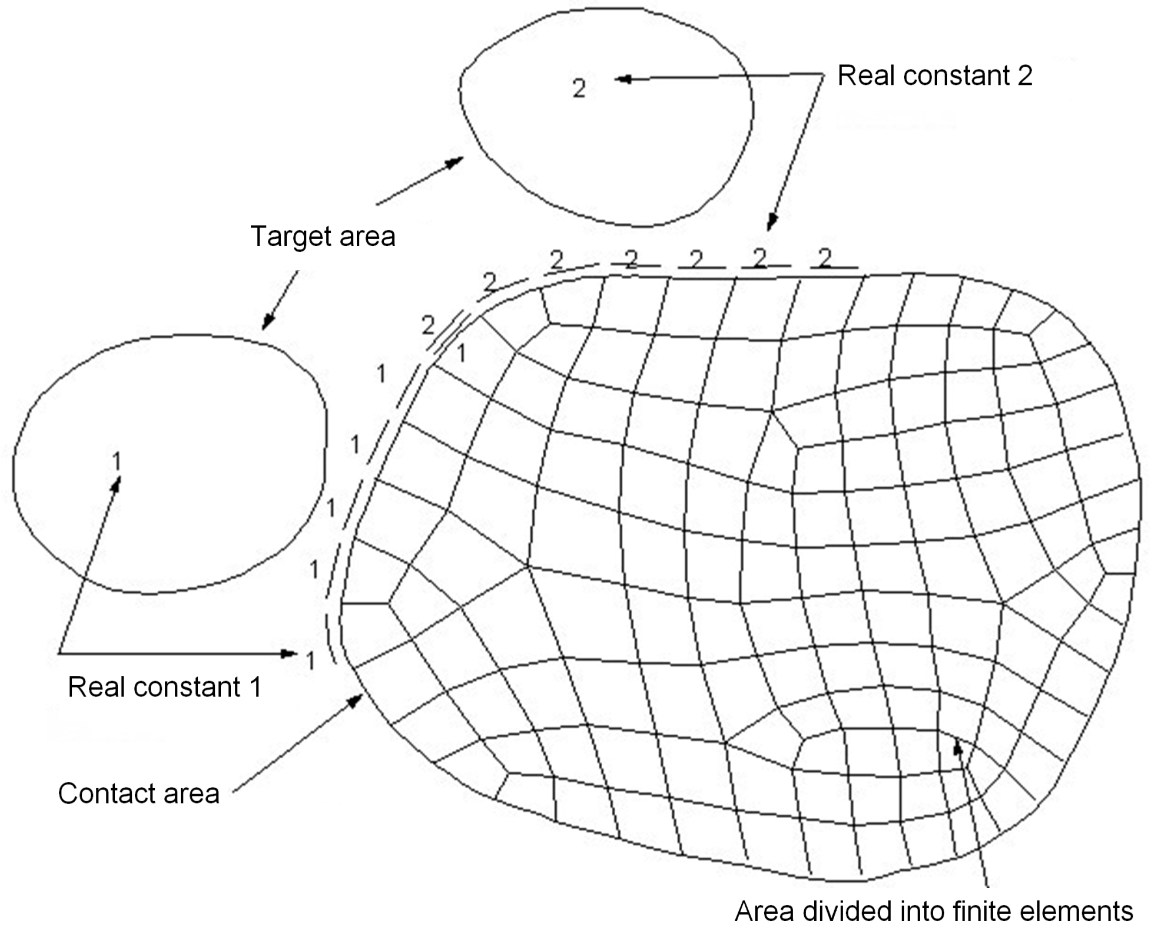
To create a so-called contact pair, it is necessary to specify the same real constants for both the target and contact surface elements (
Figure 7).
4. Results
A pile of length l = 8.0 m of a circular cross-section with a diameter of 420 mm was solved. The reinforced concrete pile was made of a material whose properties are characterised by a Young’s modulus of elasticity, Ep, of 21 GPa. The subgrade represents a low-bearing-capacity environment with a modulus of elasticity of Es = 1000 kPa. The Poisson’s number for the soil had a value of νs = 0.35. These values were chosen in order to make a comparison between analytical and numerical results. In reality, the values of the modulus of elasticity are somewhat larger.
Two load conditions were used for the calculation:
- -
The pile being loaded in the head with a horizontal force of F = 100 kN;
- -
The pile being loaded in the head with a moment of M = 100 kNm.
Three methods of supporting the footing of the pile were used for the calculation:
- -
A free end of the foot of the pile;
- -
A joint support of the foot of the pile;
- -
A clamped support for the foot of the pile.
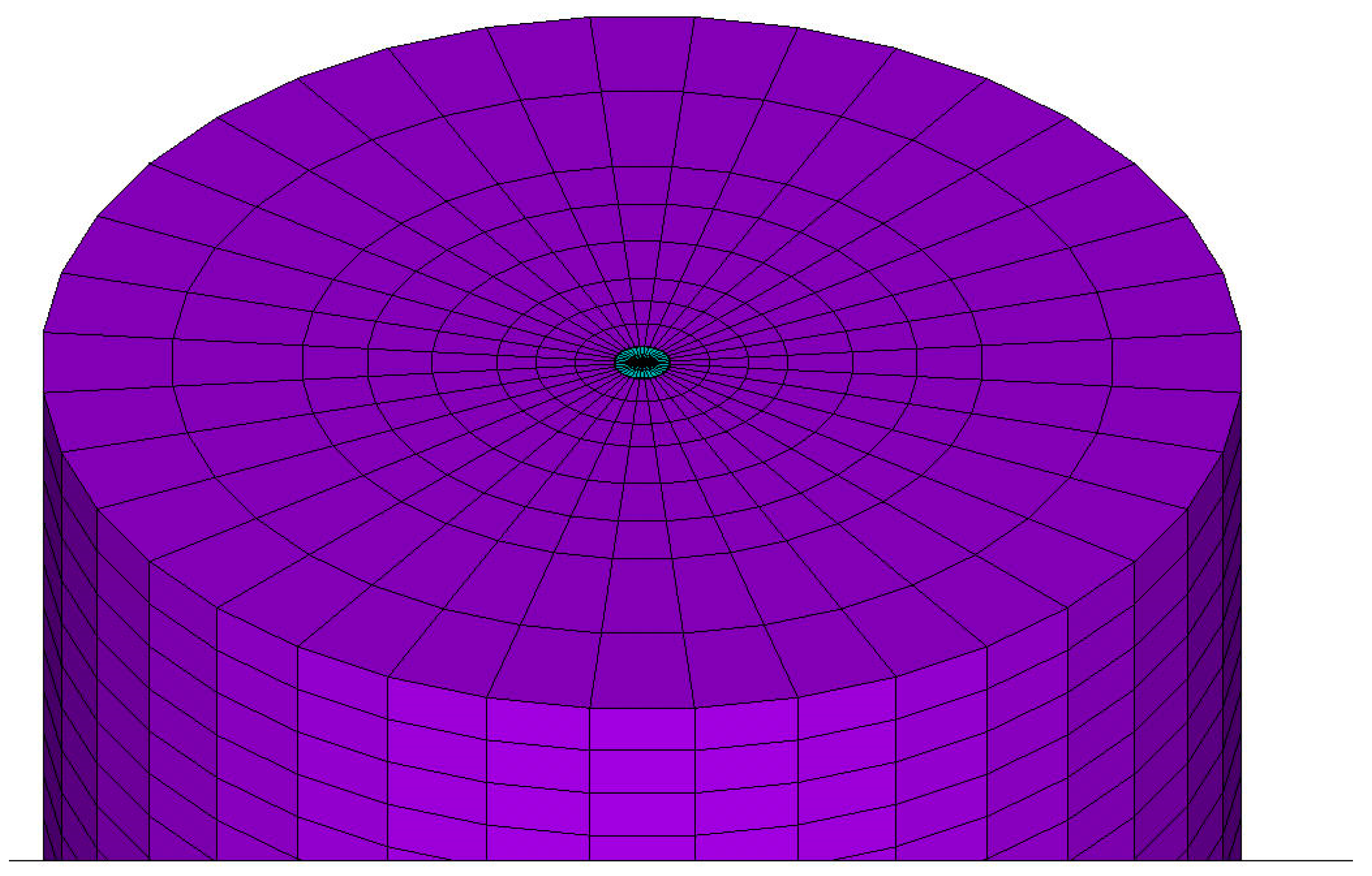
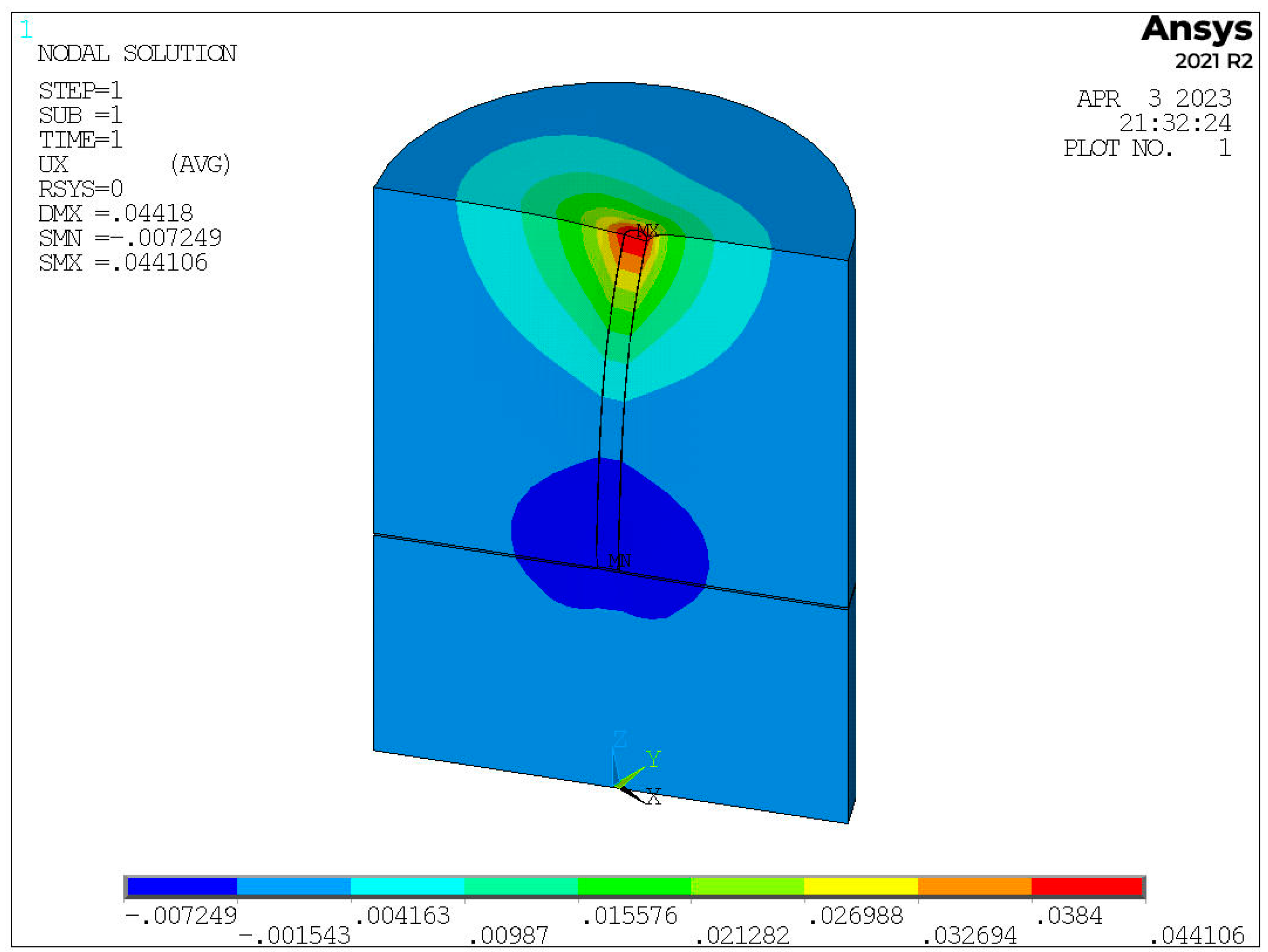
A static model of the pile and surrounding subgrade modelled using FEM in ANSYS is shown in
Figure 8. The reinforced concrete pile itself was modelled with 3D finite elements (cyan). The surrounding elastic half-space, which represents the ground mass, was modelled with 3D elements (magenta).
To model our spatial problem, a spatial 3D finite element, a hexahedron (brick), was chosen. The brick had eight nodes. The nodal parameters were three displacements—ux, uy, and uz—in the directions of the axes x, y, and z. The stiffness matrix of such an element is 24 × 24. In the ANSYS system, there is a finite element called SOLID45 in the finite element library. This particular finite element models soil. The finite element in the ANSYS element library designated as SOLID65 has similar properties. This element is recommended for modelling reinforced concrete structures. In the SOLID65 finite element, it is possible to add structural steel as a percentage of cross-sectional reinforcement. We did not consider this possibility in our examples, and we modelled the reinforced concrete pile as a homogeneous reinforced concrete cross-section with the SOLID65 element.
For individual final elements, the bricks did not have parallel walls, so it was possible to model the volume of a cylindrical shape for the pile and the surrounding soil. The meshing and the size of the final elements varied within the limits. For the reinforced concrete pile, the floor plan meshing was 100 × 120mm. The elements representing the ground massif had a grid of 400 × 600 m.
The boundary conditions in our task were based on the massif of a cylindrical earth body. This one was modelled with 3D elements of the brick type. At the edge of the cylinder, there were zero or minimal displacements. It was sufficiently far from the examined pile, and the points around the circumference of the cylinder shell were supported. All three displacements were prevented at these shell points. Given the three options for anchoring the pile heel in the soil massif, we adjusted the points at the pile heel level with the boundary conditions.
In terms of contact, three models were created:
- -
Model A, without contact elements (fixed connection);
- -
Model B, with contact elements CONTA52 (for point-to-point contact);
- -
Model C, with contact elements TARGE170 and CONTA173 (for area-to-area contact).
Figure 9 shows the results for the horizontal displacement of a pile that is loaded at the pile head by a horizontal force.
The results of the solutions of the different loading conditions, the different support methods, and the different contact models (model A, model B, and model C) are presented in the following graphs. In cases where an analytical solution to the problem was available, this is shown in the plots of deflections and bending moments along the height of the pile.
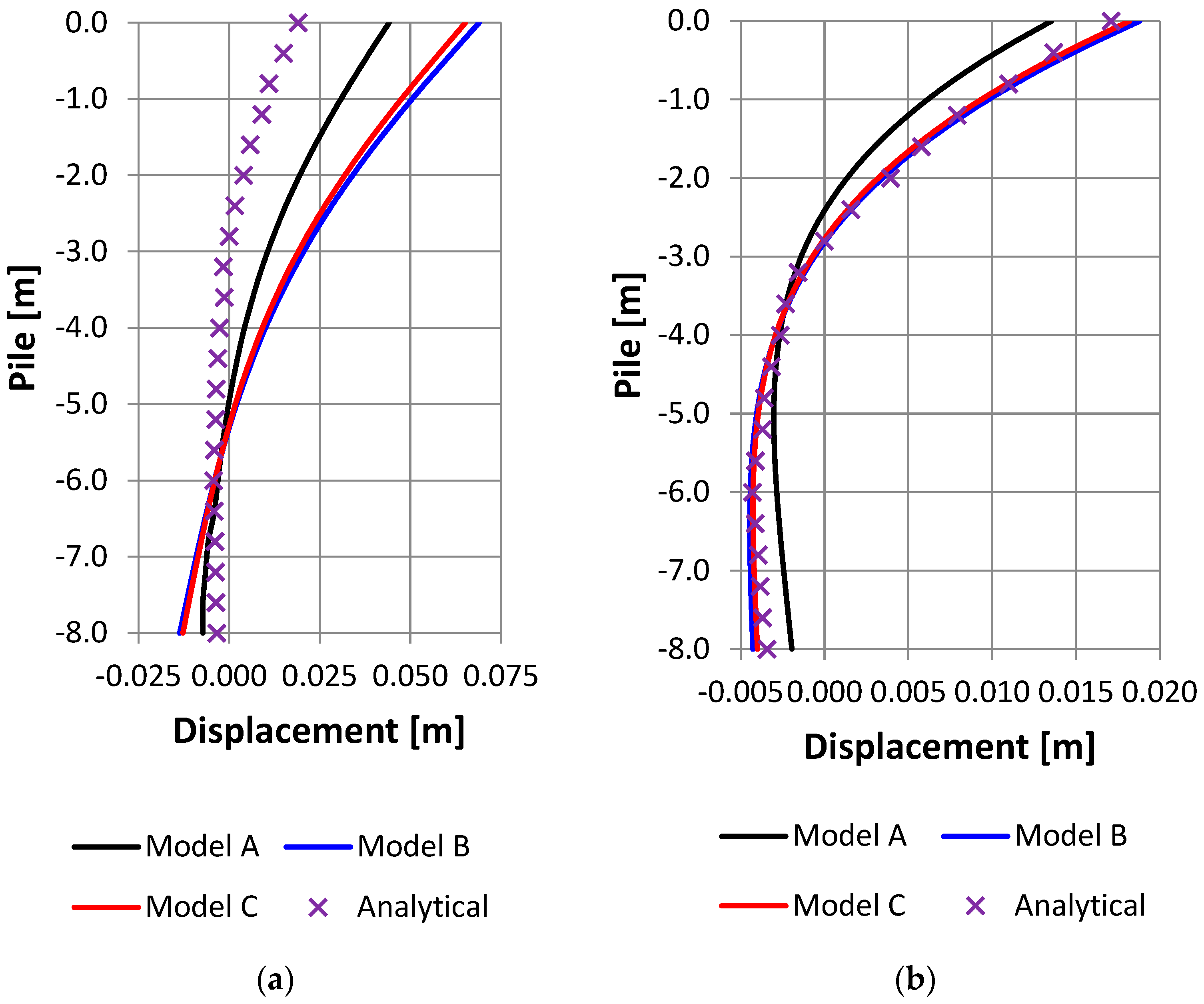
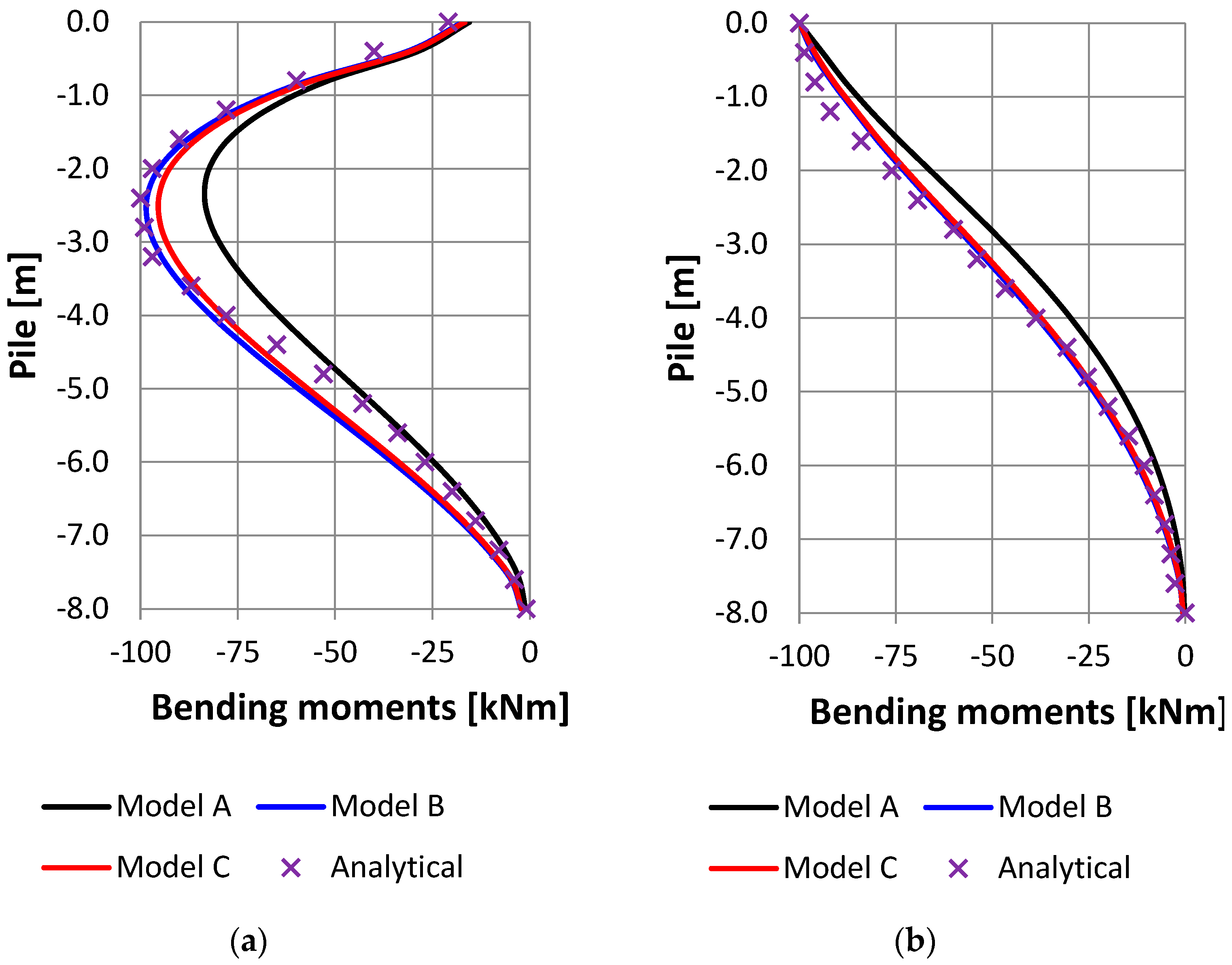
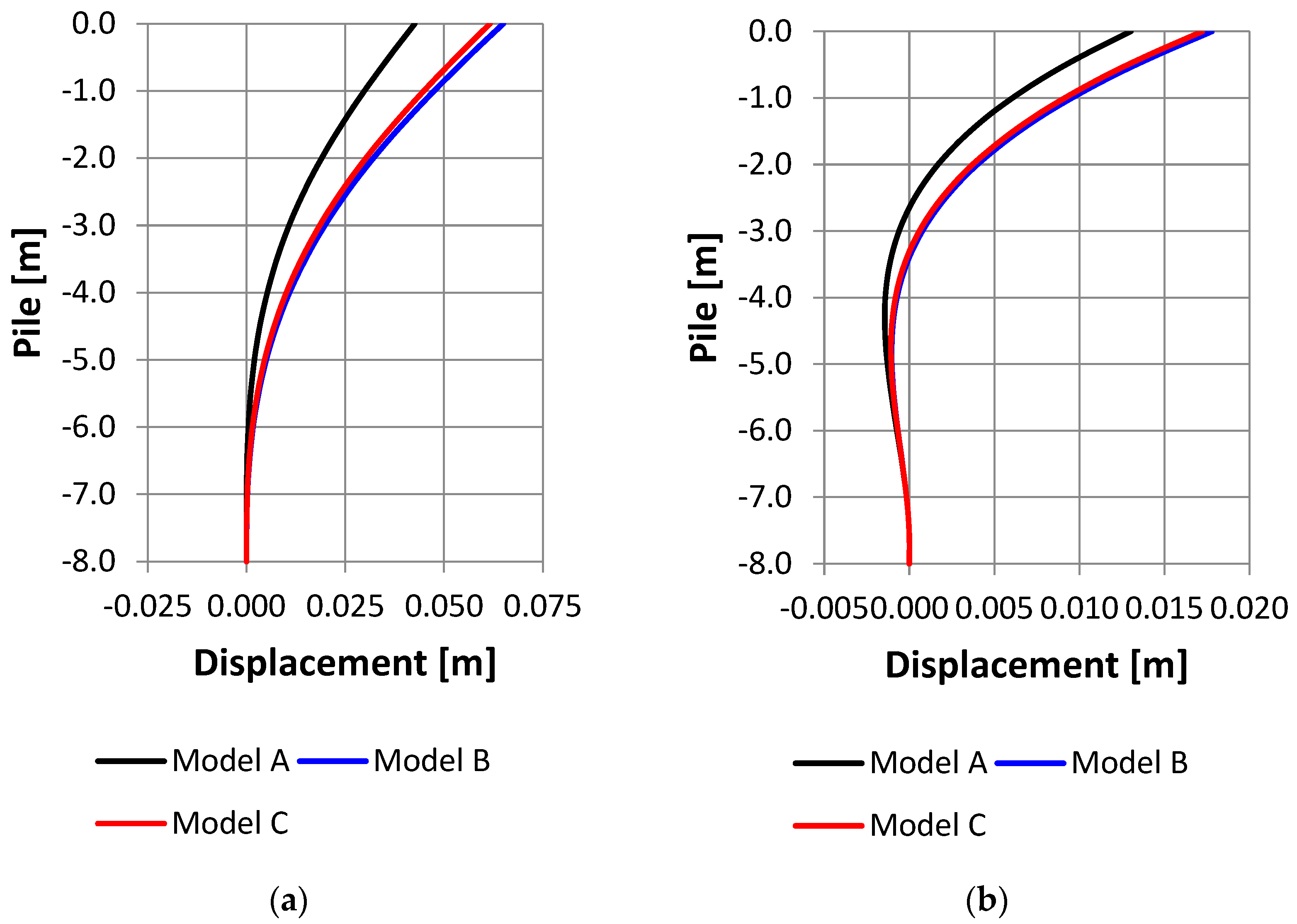
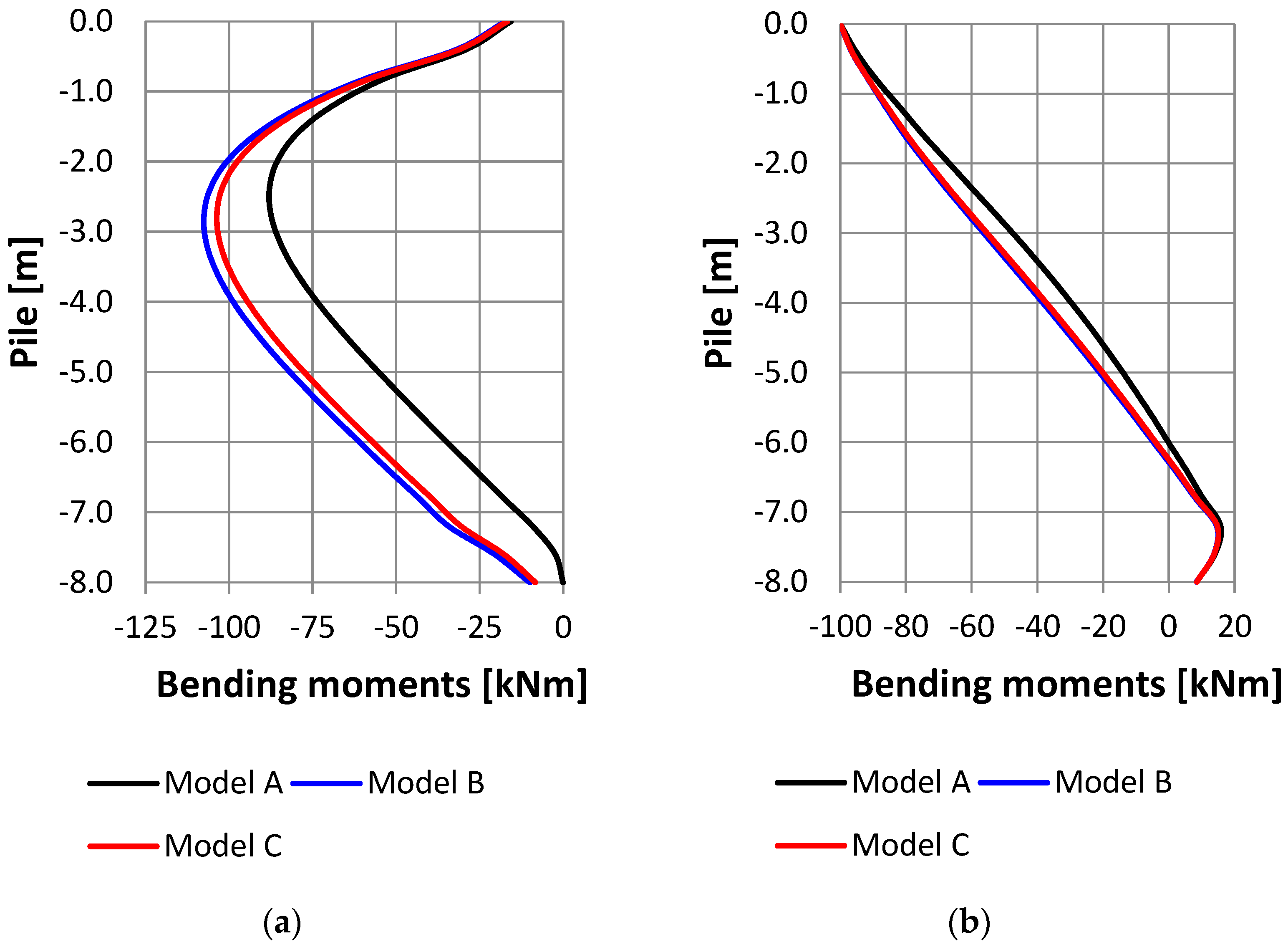
1. Solution of the example of a pile whose foot (lower end) is free. The problem was solved for a load force
F = 100 kN in the pile head and a bending moment in the pile head
M = 100 kNm. The FEA calculation was divided into three models—A, B, and C—according to the modelling of the contact between the concrete pile and the elastic subgrade (described above). Comparisons of the A, B, and C solutions with the analytical solution are denoted by X. Horizontal displacement is shown in
Figure 10 and bending moments are shown in
Figure 11.
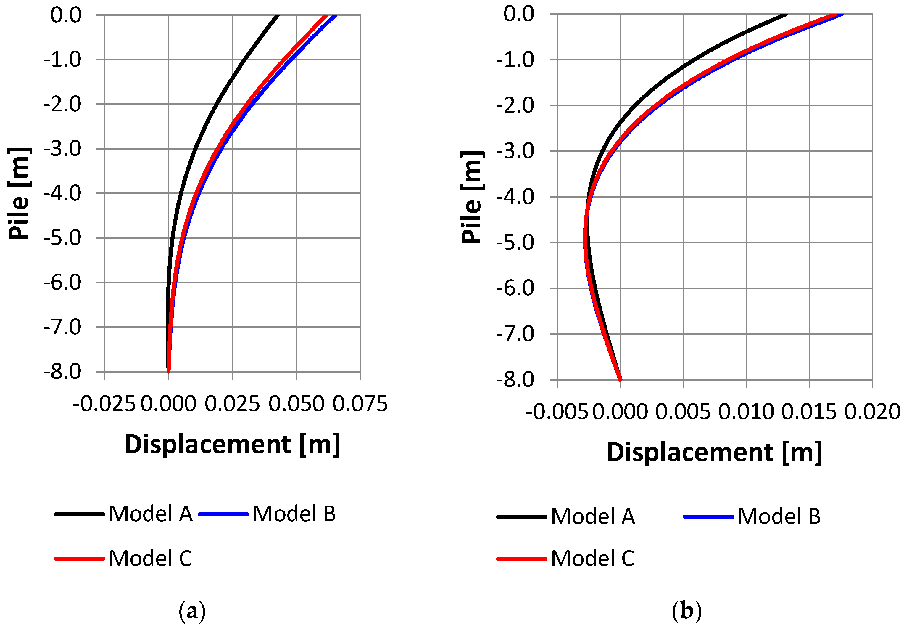
2. Solution of an example of a pile whose foot (lower end) is modelled as a jointed fit. The problem was solved for a load force, F, in the pile head and a bending moment, M, in the pile head. The calculation in the FEM was divided into three models—A, B, and C—according to the modelling of the contact between the concrete pile and the elastic foundation (described above). Horizontal displacement is shown in
Figure 12 and bending moments are shown in
Figure 13.
Solution of an example of a pile whose foot (lower end) is modelled as having perfect embedding (e.g., in a rock mass). The problem was solved for loading by the force
F in the pile head and the bending moment in the pile head. The calculation in the FEM was divided into three models—A, B, and C—according to the modelling of the contact between the concrete pile and the elastic foundation (described above). Horizontal displacement is shown in
Figure 14 and bending moments are shown in
Figure 15.
5. Discussion
In conclusion, for the pile with a free heel, a reasonably good agreement of the magnitudes of the deformations between the models with contact (models B and C) and the analytical solution A for this case of shoring was achieved with the analytical solution. For the other two cases of pile heel support, it is clear that the contact modelling solution achieves larger values compared to the non-contact model. For the moment load case, there are virtually no differences in deflections for the contact models.
The next direction or development of the field of bending piles discussed in this paper could involve the areas described below. One development could be the solution of a group of piles for common foundation structures as outlined in [
28], in terms of the design of the pile itself, the reinforcement of the pile could be addressed in detail. The optimal reinforcement of the pile as outlined in [
29] may be relevant for sustainable development. In the future, we will aim to address the action of flexure-stressed piles in layered bedrock as also mentioned in [
30]. The analysis of the dynamic action of piles under seismic loading should also not be overlooked, which is presented in [
29,
31,
32,
33].
6. Conclusions
In this paper, the solution of reinforced concrete piles in the foundation zone is demonstrated. The piles are loaded at the head with a load that induces bending effects in the pile. Case studies were conducted for three different boundary conditions for the pile footing: free pile footing, hinged pile footing, and woven pile footing. Furthermore, three case studies (A, B, and C) were conducted for contact between the reinforced concrete pile and the elastic half-space. One of the goals was to compare the analytical solution with the results obtained by the numerical FEM solution. The solution is presented in
Section 4. Point 1. The obtained results are described in the fourth part. In the Discussion, the results achieved in our work are evaluated and other possible directions of research in this area are indicated.
Author Contributions
Conceptualization, N.J. and K.T.; methodology, N.J.; software, K.T.; validation, N.J. and K.T.; formal analysis, N.J.; investigation, K.T.; resources, K.T.; data curation, N.J.; writing—original draft preparation, K.T.; writing—review and editing, K.T.; visualization, N.J.; supervision, N.J.; project administration, N.J.; funding acquisition, N.J. All authors have read and agreed to the published version of the manuscript.
Funding
This research was funded by VEGA, grant number 1/0155/23.
Data Availability Statement
The data presented in this study are available on request from the corresponding author.
Acknowledgments
Grant Agency VEGA, project No. 1/0155/23, and Grant Agency KEGA No. 030STU-4/2023, which supported this work.
Conflicts of Interest
The authors declare no conflict of interest. The research and article publication were financially supported by Grant Agency VEGA, project No. 1/0155/23. The funders had no role in the design of the study; in the collection, analyses, or interpretation of data; in the writing of the manuscript; or in the decision to publish the results.
References
- Golewski, G.L. The Specificity of Shaping and Execution of Monolithic Pocket Foundations (PF) in Hall Buildings. Buildings 2022, 12, 192. [Google Scholar] [CrossRef]
- Hemamahti, L.; Jaya, K.P. Behaviour of Precast Column Foundation Connection under Reverse Cyclic Loading. Adv. Civ. Eng. 2021, 2021, 6677007. [Google Scholar] [CrossRef]
- Jonak, J.; Karpinski, R.; Wojcik, A.; Siegmund, M. The Influence of the Physical-Mechanical Parameters of Rock on the Extent of the Initial Failure Zone under the Action of an Undercut Anchor. Materials 2021, 14, 8. [Google Scholar] [CrossRef] [PubMed]
- Sucharda, O.; Cajka, R.; Marcalikova, Z.; Pazdera, L.; Bilek, V. Diagnostic and analysis of specific soil with ground water level and plain concrete slab interaction. Acta Montan. Slovaca 2020, 25, 427–443. [Google Scholar]
- Ghasemipanah, A.; Moayed, R.Z. Analysis of Concrete Piles Under Horizontal and Vertical Simultaneous Loading with P-Y Method and Finite Element Analysis. Geotech. Geol. Eng. 2021, 39, 5857–5877. [Google Scholar] [CrossRef]
- Wu, D.; Broms, B.B.; Choa, V. Design of laterally loaded Piles in Cohesive Soils Using p-y Curves. Soils Found. 1988, 38, 17–26. [Google Scholar] [CrossRef] [Green Version]
- Liu, X.; Cai, G.; Liu, L.; Duan, W.; Puppala, A.J. Improved p-y curve models for large diameter and super-long cast-in-place piles using piezocone penetration test data. Comput. Geotech. 2021, 130, 103911. [Google Scholar] [CrossRef]
- Dash, S.; Rouholamin, M.; Lombardi, D.; Bhattacharya, S. A practical method for construction of p-y curves for liquefiable soils. Soil Dyn. Earthq. Eng. 2017, 97, 478. [Google Scholar] [CrossRef]
- Poulos, H.G.; Davis, E.H. Pile Foundation Analysis and Design; Wiley: New York, NY, USA, 1980. [Google Scholar]
- Grasshoff, H. Pfähle unter Horizontaler Erdbelastung. Master’s Thesis, Mitteilungen der Deutschen Forschungagesellschaft fur Bodenmechanik an der technischen Universität Berlin I, Berlin, Germany, 1970. [Google Scholar]
- Douglas, D.J.; Davis, E.H. The moment of Bouried Fotings due to Moment and Horizontal Load and the Moment of Anchor Plates. Geotechnique 1964, 14, 115–132. [Google Scholar] [CrossRef]
- Keawsawasvong, S.; Ukritchon, B. Ultimate lateral capacity of two dimensional plane strain rectangular pile in clay. Geomech. Eng. 2016, 11, 235–252. [Google Scholar] [CrossRef]
- Bantayehu, U.U.; Yuan-Cheng, G. CFG pile composite foundation: Its Engineering Applications and Research Advances. J. Eng. 2020, 2020, 5343472. [Google Scholar]
- Pham, T.A.; Tran, Q.-A.; Villard, P.; Dias, D. Geosynthetic-reinforced pile-supported embankments -3D discrete numerical analyses of the interaction and mobilization mechanisms. Eng. Struct. 2021, 242, 112337. [Google Scholar] [CrossRef]
- Spiller, W.R.; Stoll, R.D. Lateral Response of Piles. J. Soil. Mech. Foundaions Div. ASCE 1964, 90, 4121. [Google Scholar] [CrossRef]
- Poulos, H.G. Behavior of laterally loaded piles I-single piles. J. Soil Mech. Found 1971, 97, 711–731. [Google Scholar] [CrossRef]
- Prakash, S. Pile Foundations in Engineering Practice, 1st ed.; John Wiley & Sons, Inc.: Hoboken, NJ, USA, 1990. [Google Scholar]
- Kollar, P. Bending stressed piles. Inžinýrske Stavby 1971, 97, 711–731. (In Slovak) [Google Scholar]
- Elhamaymy, A.; Mohamed, H.M.; Benmokrane, B. Durability assessment and behavior under axial load of circular GFRP-RC piles conditioned in severe simulated marine environment. Eng. Struct. 2021, 249, 24915. [Google Scholar] [CrossRef]
- Chaimahawan, P.; Suparp, S.; Joyklad, P.; Hussain, Q. Finite element analysis of reinforced concrete pile cap using ATENA. Lat. Am. J. Solids Struct. 2021, 18, 2. [Google Scholar] [CrossRef]
- Brown, D.A.; Shie, C.F. Some numerical experiments with a three dimensional finite element model of a laterally loaded pile. Comput. Geotech. 1991, 12, 149–162. [Google Scholar] [CrossRef]
- Wulandari, P.S.; Tjandra, D. Analysis of piled raft foundation on soft soil using PLAXIS 2D. Procedia Eng. 2015, 125, 363–367. [Google Scholar] [CrossRef] [Green Version]
- Fawaz, G.; Murcia-Delso, J. Three-dimensional finite element modeling of RC columns subjected to cyclic lateral loading. Eng. Struct. 2021, 23915, 112291. [Google Scholar] [CrossRef]
- Lewiński, P.M. Accuracy assessment of linear elasticity solution for interaction of cylindrical tank with subsoil. Bull. Pol. Acad. Sci. Tech. Sci. 2021, 69, 1. [Google Scholar]
- Hong, S.; Lee, F.; Yong, K. Three-dimensional pile-soil interaction in soldier-piled excavations. Comput. Geotech. 2003, 30, 81–107. [Google Scholar] [CrossRef]
- Zhukov, N.; Balov, I. Investigation of the effect of a vertical surcharge on horizontal displacements and resistance of pile columns to horizontal loads. Soil. Mech. Found Eng. 1978, 15, 16–22. [Google Scholar] [CrossRef]
- Kotrasova, K.; Harabinova, S.; Hegedusova, I.; Kormanikova, E.; Panulinova, E. Numerical Experiment of Fluid—Structure—Soil Interaction. Procedia Eng. 2017, 190, 291–295. [Google Scholar] [CrossRef]
- Silva, F.A.N.; Delgado, J.M.P.Q.; Azevedo, A.C.; Mahfoud, T.; Khelidj, A.; Nascimento, N.; Lima, A.G.B. Diagnosis and Assessment of Deep Pile Cap Foundation of a Tall Building by Internal Expansion Reactions. Buildings 2021, 11, 104. [Google Scholar] [CrossRef]
- Conte, E.; Troncone, A.; Vena, M. Nonlinear three-dimensional analysis of reinforced concrete piles subjected to horizontal loading. Comput. Geotech. 2013, 49, 123–133. [Google Scholar] [CrossRef]
- Gazetas, G.; Dobry, R. Horizontal response of piles in layered soils. J. Geotech. Eng. 1984, 110, 20–40. [Google Scholar] [CrossRef]
- Cheng, J.; Luo, X.; Zhuang, Y.; Xu, L.; Luo, X. Experimental study on dynamic response characteristics of RPC and RC micro piles in SAJBs. Appl. Sci. 2019, 9, 2644. [Google Scholar] [CrossRef] [Green Version]
- Gil, D.F.; Mendoza, C.C.; Vásquez-Varela, L.R.; Cano, S. Physical Model of Shallow Foundation under Dynamic Loads on Sands. Infrastructures 2022, 7, 147. [Google Scholar] [CrossRef]
- Ma, J.; Luo, L.; Mu, T.; Gou, H.; Tang, Y. Experimental Study on Characteristics of Pile-Soil Interaction in Screw Piles. Buildings 2022, 12, 2091. [Google Scholar] [CrossRef]
Figure 1.
Contact stresses p(x) along the pile.
Figure 1.
Contact stresses p(x) along the pile.
Figure 2.
Contact stresses, pi, along the pile.
Figure 2.
Contact stresses, pi, along the pile.
Figure 3.
Location of contact elements in gravity wall modelling.
Figure 3.
Location of contact elements in gravity wall modelling.
Figure 4.
Model of the structure with beam and contact element.
Figure 4.
Model of the structure with beam and contact element.
Figure 5.
Representation of contact element stiffnesses.
Figure 5.
Representation of contact element stiffnesses.
Figure 6.
Contact elements CONTAxxx.
Figure 6.
Contact elements CONTAxxx.
Figure 7.
Contact pair identification.
Figure 7.
Contact pair identification.
Figure 8.
Model of the pile and the surrounding ground massif.
Figure 8.
Model of the pile and the surrounding ground massif.
Figure 9.
Results of horizontal displacements of the pile and the elastic foundation.
Figure 9.
Results of horizontal displacements of the pile and the elastic foundation.
Figure 10.
Horizontal displacement across pile height: (a) force load, 100 kN; (b) moment load, 100 kNm.
Figure 10.
Horizontal displacement across pile height: (a) force load, 100 kN; (b) moment load, 100 kNm.
Figure 11.
Bending moment across pile height: (a) force load, 100 kN; (b) moment load, 100 kNm.
Figure 11.
Bending moment across pile height: (a) force load, 100 kN; (b) moment load, 100 kNm.
Figure 12.
Horizontal displacement across pile height: (a) force load, 100 kN; (b) moment load, 100 kNm.
Figure 12.
Horizontal displacement across pile height: (a) force load, 100 kN; (b) moment load, 100 kNm.
Figure 13.
Bending moment across pile height: (a) force load, 100 kN; (b) moment load, 100 kNm.
Figure 13.
Bending moment across pile height: (a) force load, 100 kN; (b) moment load, 100 kNm.
Figure 14.
Horizontal displacement across pile height: (a) force load, 100 kN; (b) moment load, 100 kNm.
Figure 14.
Horizontal displacement across pile height: (a) force load, 100 kN; (b) moment load, 100 kNm.
Figure 15.
Bending moment across pile height: (a) force load, 100 kN; (b) moment load, 100 kNm.
Figure 15.
Bending moment across pile height: (a) force load, 100 kN; (b) moment load, 100 kNm.
| Disclaimer/Publisher’s Note: The statements, opinions and data contained in all publications are solely those of the individual author(s) and contributor(s) and not of MDPI and/or the editor(s). MDPI and/or the editor(s) disclaim responsibility for any injury to people or property resulting from any ideas, methods, instructions or products referred to in the content. |
© 2023 by the authors. Licensee MDPI, Basel, Switzerland. This article is an open access article distributed under the terms and conditions of the Creative Commons Attribution (CC BY) license (https://creativecommons.org/licenses/by/4.0/).


