
Architectural Glass under Climatic Actions and Fire: Review of State of the Art, Open Problems and Future Perspectives


Abstract
:1. Introduction
2. Thermal Actions
2.1. The Climatic Actions
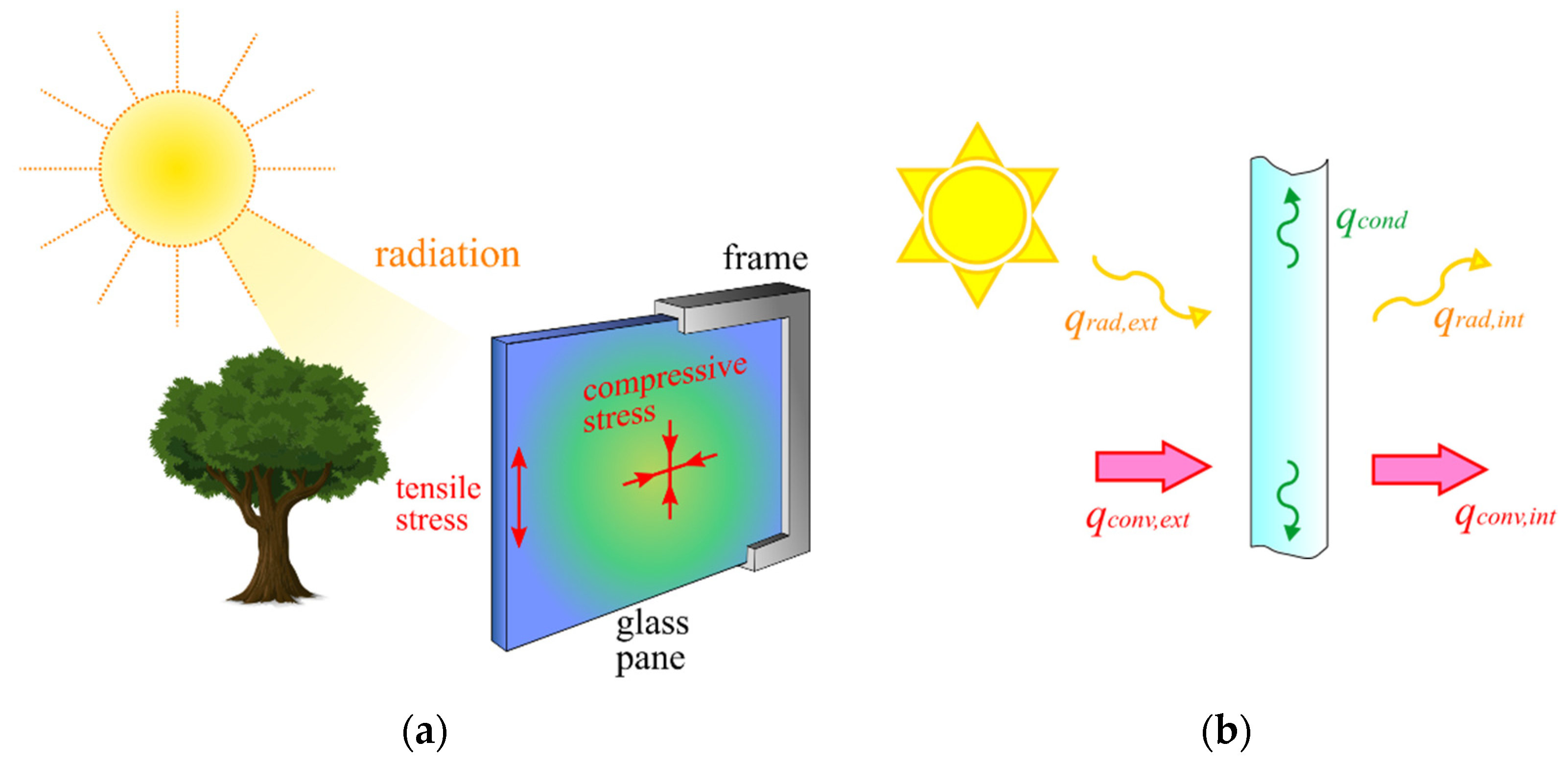
2.1.1. Heat Radiation
2.1.2. Heat Convection
2.1.3. Solar Radiation
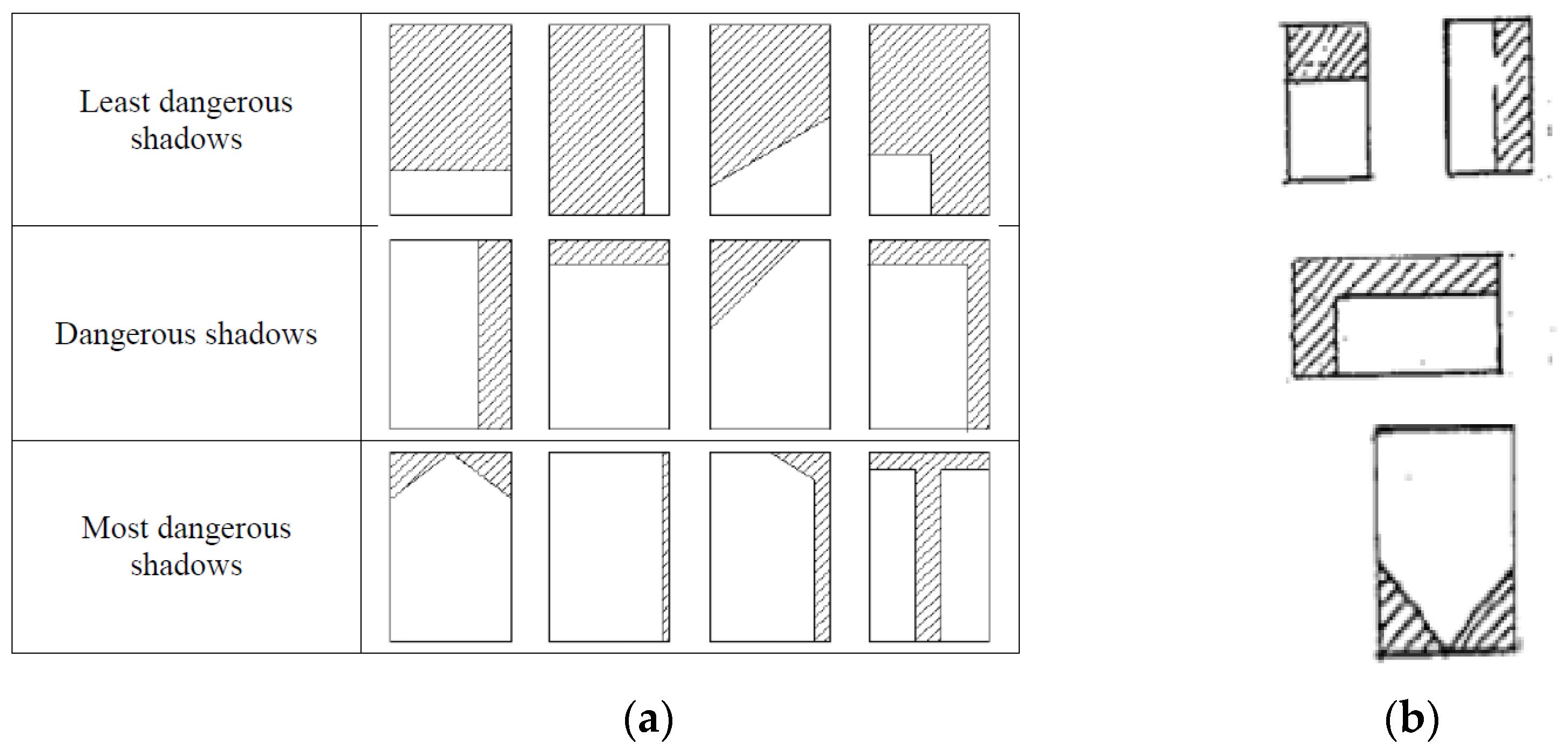
2.1.4. The Influence of Shadows and Frame
- in glass portions directly invested by the solar radiation;
- in the shaded glass portions;
- in the framed region.
2.1.5. Heat Conduction
2.1.6. Heat Storage
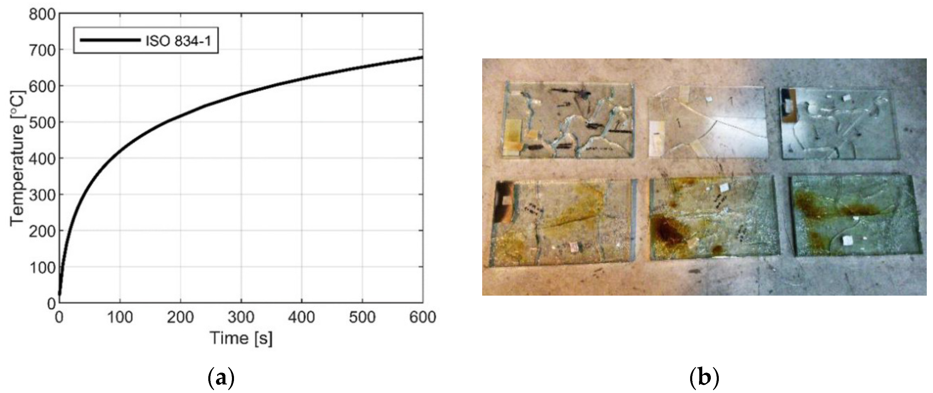
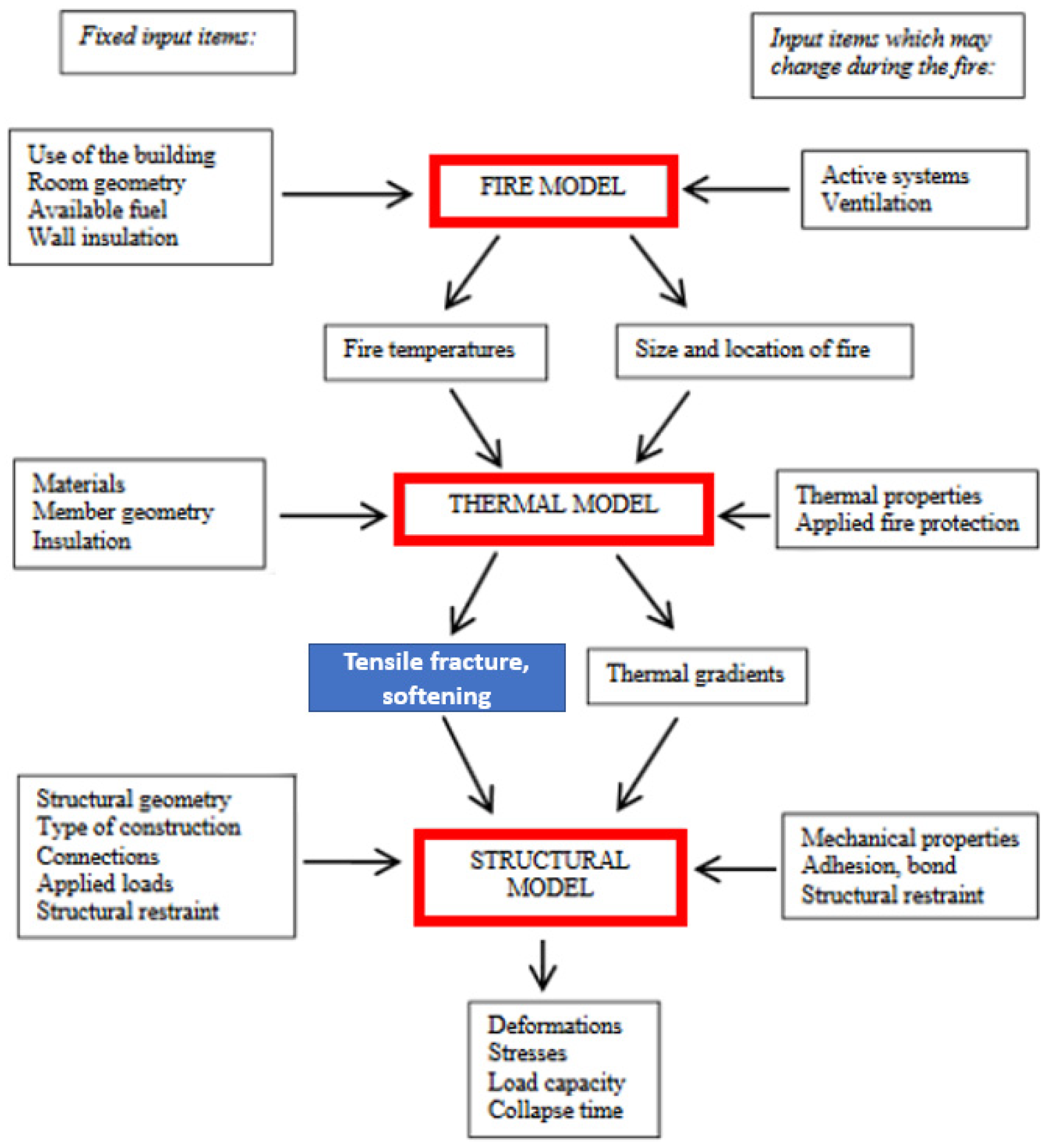
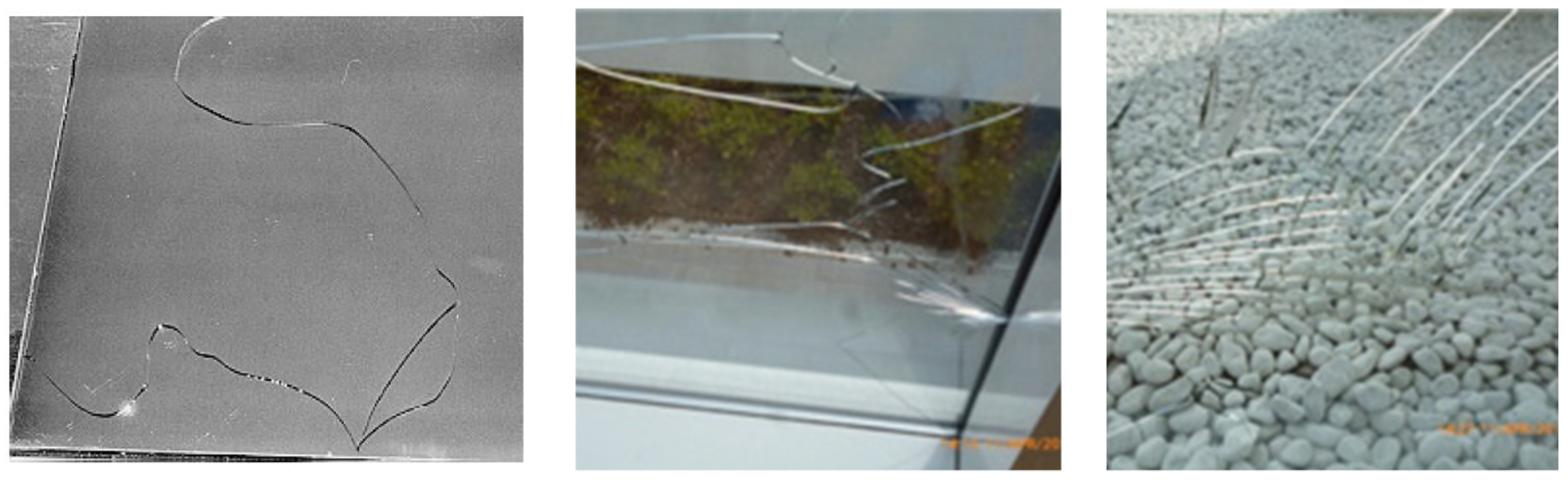
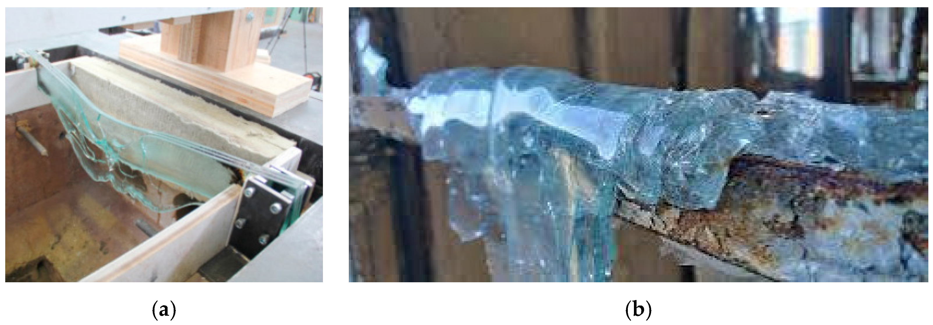
2.2. Fire
3. The Determination of the Temperature Field in Glazing
3.1. The Governing Equations and Boundary Conditions
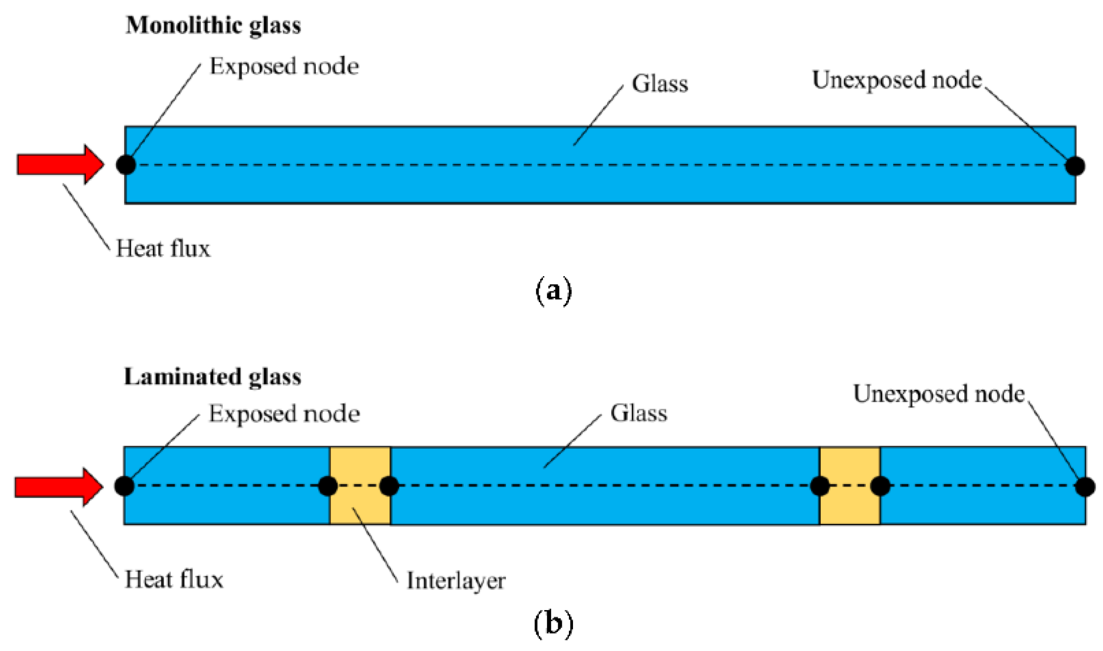
3.1.1. Monolithic Glass
3.1.2. Laminated Glass
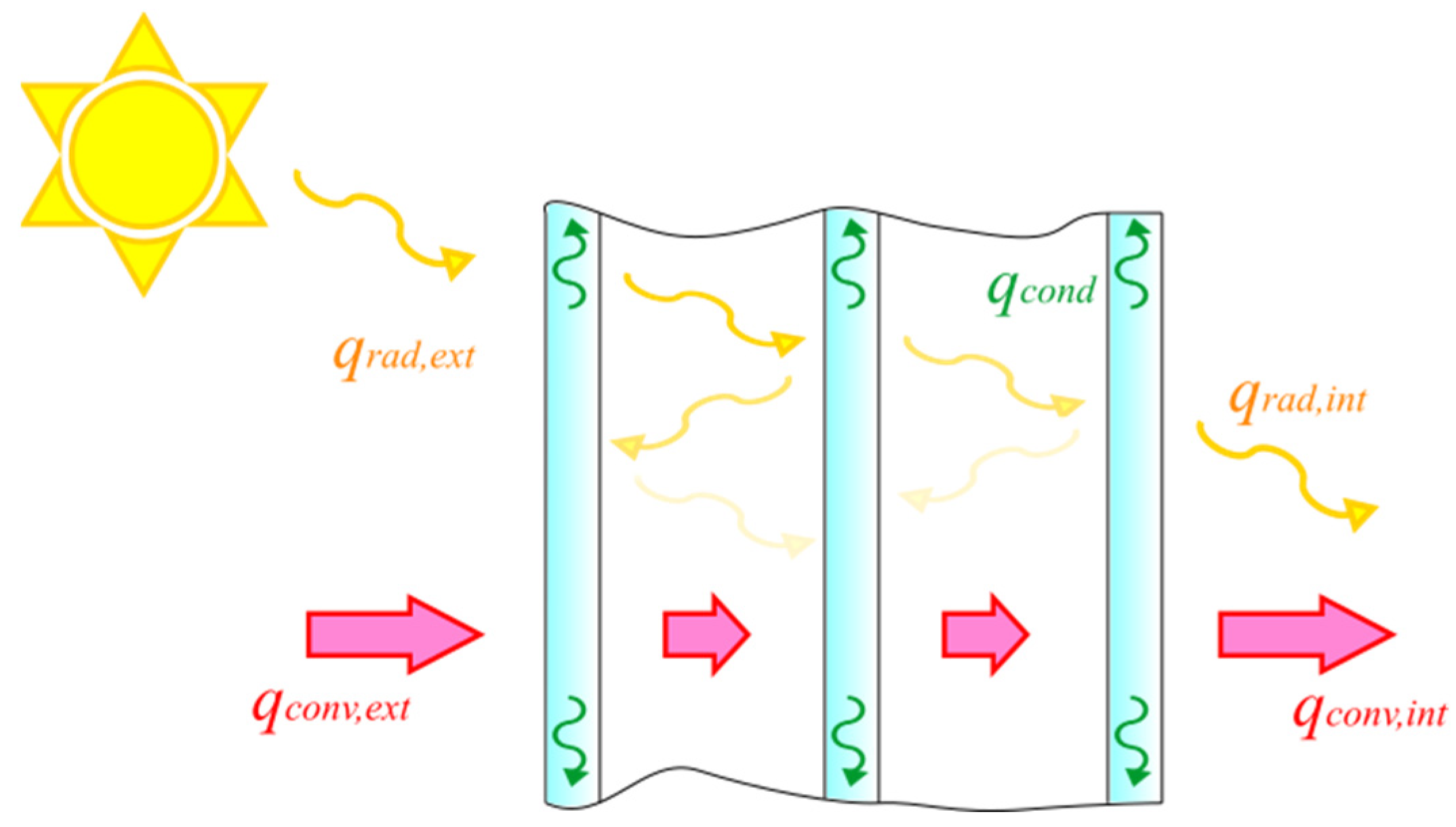
3.1.3. Insulating Glass Units
- Heat convection occurs at the external surface, between the “front” panel and the external air, as well as at the internal surface between the “rear” panel and the indoors, and between each panel and the gas occupying the adjacent cavities. The internal convective heat transfer coefficients depend on the gas type and the cavity thickness [90,91,92,93]. The presence of the spacers usually prevents heat exchange in the edge region; hence, the heat flux at the periphery surfaces of the cavity is null [94]. Note that this implies that the (time-dependent) gas temperature is an additional variable of the thermal problem, which remains to be determined [8,55,79].
- When the radiant energy from the sun and surrounding environment strikes the front and rear glass pane, a part of the energy is absorbed by the material, a part is reflected, and the remaining part is transmitted according to the glass’ absorptivity, reflectivity and transmissivity. Hence, a fraction of the energy is transmitted to the inner panes and will be further split in three parts. This leads to multiple reflections between the glass panes comprising the IGUs, as schematically indicated in Figure 4. Several methods have been proposed to evaluate this multiple-reflection phenomenon [48,91,95,96], with the aim of calculating the effective thermal properties (transmittance and insulation) of multiple glazing. The system of equations governing the problem is usually solved by numerical methods [48,97,98,99,100], but there are simple cases in which the solution can be analytically determined [55,56].
3.2. Analitycal and Numerical Solutions for Glazing under Climatic Actions
3.3. Numerical Solutions for Glazing under Fire
4. The Thermal Stress

4.1. Climatic Actions
4.2. Fire
4.2.1. Material Properties in Fire
4.2.2. Numerical Solutions

5. Standards and Codes
5.1. Physical and Mechanical Properties of Glass and Glazing Components
5.2. Climatic Actions
5.2.1. Heat-Exchange Contributions

| Heat Radiation | ||
|---|---|---|
| CNR DT 210 | - | - |
| EN ISO 6946 | 4.59 W/(m2K) (Table 5) | 5.13 W/(m2K) (Table 5) |
| EN 673 | 4.1 W/(m2K) Vertical (uncoated) soda lime glass surfaces | - |
| EN ISO 10077-1 | - | - |
| DTU 39 | acc. to EN 673 (only for IGU) | - |
| ISO 15099 | ||
| EN 52022-3 | - | - |
| Belgian Guidelines | - | - |
| Pilkington Instructions | - | - |
| Heat Convection | ||||
|---|---|---|---|---|
| CNR DT 210 | Max summer and min winter air T (50 y return period). Initial assumption ΔT = ±30 °C between extreme values. | Tables f (standardized internal areas) (UNI 5364) | - | - |
| EN ISO 6946 | - | - | 3.6 W/(m2K) (for free convection) | - |
| EN 673 | - | - | - | - |
| EN ISO 10077-1 | - | - | - | - |
| DTU 39 (1) | TR: Table 4 for each seasonf (max and min diurnal T and amplitude) (France only) SS: Winter: min diurnal T (France maps) + 5 °C | Constant value f (facade inclination and season) (Table 5) | acc. to EN 673 (only for IGU) | - |
| ISO 15099 | Reference BC (§8.2) Win: 0 °C Sum: 30 °C | Reference BC (§8.2) Win: 20 °C Sum: 25 °C | ▪ Nu (λ/H) (2) (natural convection) ▪ 4 + 4 v (2) (forced air flow) [from EN ISO 6946] | ▪ Nu (λ/H) (2) (natural convection) ▪ 4 + 4 v (2) (forced air flow for product comparison) or 4.7 + 7.6 v (forced air flow in real buildings)- if surface windward (3): v = 0.25 V for V > 2 m/s v = 0.5 V for V ≤ 2 m/s - if surface leeward (3): v = 0.3 + 0.05 V |
| Reference BC (§8.2) Winter: 3.6 W/(m2K) Summer: 2.5 W/(m2K) | Reference BC (§8.2) Winter: 20 W/(m2K) [4 m/s] Summer: 8 W/(m2K) [2 m/s] | |||
| EN 52022-3 | Reference BC (§6.4.6) 5 °C Summer (§6.4.6) 25 °C | Reference BC (§6.4.6) 20 °C Summer (§6.4.6) 25 °C | Reference BC (§6.4.6) 3.6 W/(m2K) Summer (§6.4.6) 2.5 W/(m2K) | Reference BC (§6.4.6) 18 W/(m2K) Summer (§6.4.6) 8 W/(m2K) (for v = 1 m/s) |
| Belgian Guidelines | - | - | - | - |
| Pilkington Instructions | - | - | - | - |
| Surface Exchange Coefficients (Convection + Radiation) | ||||
|---|---|---|---|---|
| Vertical | Horizontal (Or Inclined) | Vertical | Horizontal (Or Inclined) | |
| CNR DT 210 | 7.7 W/(m2K) [1/ = 0.13 m2K/W] | 10 W/(m2K) [1/ = 0.1 m2K/W] | 25 W/(m2K) [1/ = 0.04 m2K/W] | |
| EN ISO 6946 | 7.7 W/(m2K) = 0.13 m2 K/W] (horizontal heat flow) | 10 W/(m2K) [ = 0.1 m2 K/W] (Upward heat flow) 5.8 W/(m2K) [ = 0.17 m2 K/W] (Downward heat flow) | 25 W/(m2K) [ = 0.04 m2 K/W] (Tables 5 and 7) | |
| EN 673 | 7.7 W/(m2K) [1/ = 0.13 m2K/W] | EN ISO 6946 | 25 W/(m2K) [1/ = 0.04 m2K/W] | |
| EN ISO 10077-1 | 7.7 W/(m2K) [1/ = 0.13 m2K/W] | 10 W/(m2K) [1/ = 0.1 m2K/W] | 25 W/(m2K) [1/ = 0.04 m2K/W] | |
| DTU 39 | 9 W/(m2K) | 11 W/(m2K) (Upward flux) 6 W/(m2K) (Downward flux) | 11 W/(m2K) (winter/mid-season) 13 W/(m2K) (summer) | 12 W/(m2K) (winter/mid-season) 14 W/(m2K) (summer) |
| ISO 15099 | §8.5 h = hR + hC | §8.5 h = hR + hC | ||
| EN 52022-3 | - | - | ||
| Belgian Guidelines | 8 W/m2K | 16 W/m2K | ||
| Pilkington Instructions | - | - | ||
| Solar Radiation | Shadows | |
|---|---|---|
| CNR DT 210 | Max summer solar irradiance incident on a vertical surface referred to different latitudes (Table 4.13 taken from UNI 10349). | See Figure 9 of current paper |
| EN ISO 6946 | - | - |
| EN 673 | - | - |
| EN ISO 10077-1 | - | - |
| DTU 39 (1) | f (season, daytime, facade orientation/inclination) SS: Table 6 (location/altitude) + corrective coeff. (Table 7) inclination/season (summer/winter) TR: Figure 23 (variable graphs) | 10% of the global solar radiationin the shaded parts SS: min 75 W/m2 TR: Figure 24 f (season) |
| ISO 15099 | Winter (§8.2.2) 300 W/m2 Summer (§8.2.3) 500 W/m2 | - |
| EN 52022-3 | Reference BC (§6.4.6) 300 W/m2 Summer (§6.4.6) 500 W/m2 | - |
| Belgian Guidelines | 10° < θ < 75° G = 850 W/m2 θ = 90° G = 750 W/m2 θ angle with respect to the horizontal | Coefficient f (shadow shape and glass type—single/double) Values: 1.1–1.5 |
| Pilkington Instructions | Graphs f (location) in UK and rest of the world. | Shadow Factor No shadow: 1.0 Mobile shadow: 1.11 Static shadow: Figure 31 |
5.2.2. Determination of the Temperature Field
- Solar radiation maximum intensity (W/m2) (for angles of 10° to 75° with respect to the horizontal, G = 850 W/m2, for 90°, G = 750 W/m2).
- Absorption coefficient of the single glass (-), as defined in Section 2.1.3.
- A
- Maximum amplitude of the average diurnal temperature fluctuations over at least 10 years (K or °C). This is a constant value depending on the geographical position (from 10 to 13 K).
- Heat transfer coefficient at the outer surface ( = 16 W/m2K).
- Heat transfer coefficient at the inner surface ( = 8 W/m2K).
5.2.3. Thermal Stress
5.3. Fire
5.3.1. Reaction to Fire
- Glass not containing organic materials, i.e., basic glass, coated glass, toughened glass, heat-strengthened glass, chemically strengthened glass, mirrors, glass blocks and paver units, are classified as A1 according to Commission Decision 96/603/EC, as amended by Commission Decision 2000/605/EC.
- Glass containing a certain amount of organic material, i.e., laminated (safety) glass and insulating glass units, should be tested for their reaction to fire according to EN 13501-1.
5.3.2. Resistance to Fire
- Limitation of fire spread on the surface and inside of the facade system;
- Demonstration of fire performance for systems that do not follow or cannot meet the fire performance characteristics for individual components, for example, insulation that cannot be categorized into the required reaction-to-fire class;
- Requirements regarding fire’s spread through facades from one room to another (through external surfaces, but also through cavities and facade floor junctions);
- Limitation or avoidance of falling parts and/or burning debris/droplets;
- Limitation of smouldering fires.
| Country | Assessment Method |
|---|---|
| Austria | ÖNORM B 3800-5 [182] |
| Czech Republic | ČSN ISO 13785-1 [183] |
| Denmark, Sweden, Norway | SP Fire 105 [184] |
| Finland |
|
| France | LEPIR 2 [186] |
| Germany | |
| Hungary | MSZ 14800-6 [189] |
| Ireland | BS 8414 (BR 135) |
| Poland | PN-B-02867 [190] |
| Switzerland, Liechtenstein |
|
6. Conclusions
Author Contributions
Funding
Data Availability Statement
Conflicts of Interest
References
- Alwetaishi, M. Impact of glazing to wall ratio in various climatic regions: A case study. J. King Saud Univ. Eng. Sci. 2019, 31, 6–18. [Google Scholar] [CrossRef]
- Hilliaho, K.; Nordquist, B.; Wallentèn, P.; Hamid, A.A.; Lahdensivu, J. Energy saving and indoor climate effects of an added glazed facade to a brick wall building: Case study. J. Build. Eng. 2016, 7, 246–262. [Google Scholar] [CrossRef]
- Kim, D.; Cox, S.J.; Cho, H.; Yoon, J. Comparative investigation on building energy performance of double skin façade (DSF) with interior or exterior slat blinds. J. Build. Eng. 2018, 20, 411–423. [Google Scholar] [CrossRef]
- Bedon, C.; Zhang, X.H.; Santos, F.; Honfi, D.; Kozlowski, M.; Arrigoni, M.; Figuli, L.; Lange, D. Performance of structural glass facades under extreme loads–Design methods, existing research, current issues and trends. Constr. Build. Mater. 2018, 163, 921–937. [Google Scholar] [CrossRef]
- Stahn, D. Thermal stresses in heat-absorbing building glass subjected to solar radiation. In Thermal Stresses in Severe Environments; Springer: Berlin/Heidelberg, Germany, 1980; pp. 305–323. [Google Scholar]
- Poláková, M.; Schäfer, S.; Elstner, M. Thermal Glass Stress Analysis–Design Considerations. In Challenging Glass Conference Proceedings; CGC: Sarasota, FL, USA, 2018; pp. 725–740. [Google Scholar]
- Teotia, M.; Soni, R.K. Applications of finite element modelling in failure analysis of laminated glass composites: A review. Eng Fail Anal 2018, 94, 412–437. [Google Scholar] [CrossRef]
- Schwind, G.; Paschke, F.; Schneider, J. Case Studies on the Thermally Induced Stresses in Insulating Glass Units via Numerical Calculation. In Challenging Glass Conference, Proceedings of the Conference on Architectural and Structural Applications of Glass, Ghent, Belgium, 23–24 June 2022; CGC: Sarasota, FL, USA, 2022; Volume 8. [Google Scholar]
- Vengatesan, K. Windows Film to Glass: Numerical Simulation Software for Avoiding Thermal Stress. Master’s Thesis, IST Tecnico Lisboa, Lisbon, Portugal, 2017. [Google Scholar]
- Bedon, C. Structural Glass Systems under Fire: Overview of Design Issues, Experimental Research, and Developments. Adv. Civ. Eng. 2017, 2017, 2120570. [Google Scholar] [CrossRef]
- EU 305/2011; Regulation (EU) No 305/2011 of the European Parliament and of the Council of 9 March 2011 Laying down Harmonised Conditions for the Marketing of Construction Products and Repealing Council Directive 89/106/EEC. Official Journal of the European Union: Maastricht, The Netherlands, 2011.
- ISO 15099; Thermal Performance of Windows, Doors and Shading Devices—Detailed Calculation. International Organization for Standardization: Geneva, Switzerland, 2003.
- Li, M.Y.; Jiang, Y.J.; Coimbra, C.F.M. On the determination of atmospheric longwave irradiance under all-sky conditions. Sol. Energy 2017, 144, 40–48. [Google Scholar] [CrossRef]
- Karn, A.; Chintala, V.; Kumar, S. An investigation into sky temperature estimation, its variation, and significance in heat transfer calculations of solar cookers. Heat Transf.-Asian Res. 2019, 48, 1830–1856. [Google Scholar] [CrossRef]
- Berger, X.; Buriot, D.; Garnier, F. About the Equivalent Radiative Temperature for Clear Skies. Sol. Energy 1984, 32, 725–733. [Google Scholar] [CrossRef]
- Gliah, O.; Kruczek, B.; Etemad, S.G.; Thibault, J. The effective sky temperature: An enigmatic concept. Heat Mass Transf. 2011, 47, 1171–1180. [Google Scholar] [CrossRef]
- Swinbank, W.C. Long-wave radiation from clear skies. Q. J. R. Meteorol. Soc. 1963, 89, 339–348. [Google Scholar] [CrossRef]
- Bergman, T.L.; Incropera, F.P.; DeWitt, D.P.; Lavine, A.S. Fundamentals of Heat and Mass Transfer; Wiley: New York, NY, USA, 2011. [Google Scholar]
- Lienhard, J.H.I.; Lienhard, J.H.V. A Heat Transfer Textbook, 5th ed.; Phlogiston Press: London, UK, 2019. [Google Scholar]
- EN ISO 6946; Building Components and Building Elements–Thermal Resistance and Thermal Transmittance–Calculation Methods. European Committee for Standardization (CEN): Brussels, Belgium, 2017.
- Marino, C.; Nucara, A.; Pietrafesa, M.; Polimeni, E. The effect of the short wave radiation and its reflected components on the mean radiant temperature: Modelling and preliminary experimental results. J. Build. Eng. 2017, 9, 42–51. [Google Scholar] [CrossRef]
- Churchill, S.W.; Chu, H.H.S. Correlating Equations for Laminar and Turbulent Free Convection from a Vertical Plate. Int. J. Heat Mass. Transf 1975, 18, 1323–1329. [Google Scholar] [CrossRef]
- Poirier, D.R.; Geiger, G.H. (Eds.) Correlations and Data for Heat Transfer Coefficients. In Transport Phenomena in Materials Processing; Springer International Publishing: Cham, Switzerland, 2016; pp. 247–279. [Google Scholar]
- Loveday, D.L.; Taki, A.H. Convective heat transfer coefficients at a plane surface on a full-scale building facade. Int. J. Heat Mass Transf. 1996, 39, 1729–1742. [Google Scholar] [CrossRef]
- Mirsadeghi, M.; Costola, D.; Blocken, B.; Hensen, J.L.M. Review of external convective heat transfer coefficient models in building energy simulation programs: Implementation and uncertainty. Appl. Therm. Eng. 2013, 56, 134–151. [Google Scholar] [CrossRef]
- Defraeye, T.; Blocken, B.; Carmeliet, J. Convective heat transfer coefficients for exterior building surfaces: Existing correlations and CFD modelling. Energ Convers. Manag. 2011, 52, 512–522. [Google Scholar] [CrossRef]
- Kahsay, M.T.; Bitsuamlak, G.; Tariku, F. Numerical analysis of convective heat transfer coefficient for building facades. J. Build. Phys. 2019, 42, 727–749. [Google Scholar] [CrossRef]
- Montazeri, H.; Blocken, B.; Derome, D.; Carmeliet, J.; Hensen, J.L.M. CFD analysis of forced convective heat transfer coefficients at windward building facades: Influence of building geometry. J. Wind Eng. Ind. Aerodyn. 2015, 146, 102–116. [Google Scholar] [CrossRef]
- Zhang, J.Y.; Zhao, L.; Deng, S.; Xu, W.C.; Zhang, Y. A critical review of the models used to estimate solar radiation. Renew. Sustain. Energy Rev. 2017, 70, 314–329. [Google Scholar] [CrossRef]
- Compagnon, R. Solar and daylight availability in the urban fabric. Energ Build. 2004, 36, 321–328. [Google Scholar] [CrossRef]
- Alqaed, S. Effect of annual solar radiation on simple facade, double-skin facade and double-skin facade filled with phase change materials for saving energy. Sustain. Energy Technol. 2022, 51, 101928. [Google Scholar] [CrossRef]
- Unguresan, P.V.; Porumb, R.A.; Petreus, D.; Pocola, A.G.; Pop, O.G.; Balan, M.C. Orientation of Facades for Active Solar Energy Applications in Different Climatic Conditions. J. Energy Eng. 2017, 143. [Google Scholar] [CrossRef]
- Valladares-Rendon, L.G.; Schmid, G.; Lo, S.L. Review on energy savings by solar control techniques and optimal building orientation for the strategic placement of facade shading systems. Energy Build. 2017, 140, 458–479. [Google Scholar] [CrossRef]
- Perez, G.; Coma, J.; Sol, S.; Cabeza, L.F. Green facade for energy savings in buildings: The influence of leaf area index and facade orientation on the shadow effect. Appl. Energ. 2017, 187, 424–437. [Google Scholar] [CrossRef]
- Norris, D.J. Solar Radiation on Inclined Surfaces. Sol. Energy 1966, 10, 72–76. [Google Scholar] [CrossRef]
- Demain, C.; Journée, M.; Bertrand, C. Evaluation of different models to estimate the global solar radiation on inclined surfaces. Renew Energy 2013, 50, 710–721. [Google Scholar] [CrossRef]
- Maleki, S.A.M.; Hizam, H.; Gomes, C. Estimation of Hourly, Daily and Monthly Global Solar Radiation on Inclined Surfaces: Models Re-Visited. Energies 2017, 10, 134. [Google Scholar] [CrossRef]
- Redweik, P.; Catita, C.; Brito, M. Solar energy potential on roofs and facades in an urban landscape. Sol. Energy 2013, 97, 332–341. [Google Scholar] [CrossRef]
- Chow, T.T.; Chan, A.L.S.; Fong, K.F.; Lin, Z. Hong Kong solar radiation on building facades evaluated by numerical models. Appl. Therm. Eng. 2005, 25, 1908–1921. [Google Scholar] [CrossRef]
- Han, J.M.; Choi, E.S.; Malkawi, A. CoolVox: Advanced 3D convolutional neural network models for predicting solar radiation on building facades. Build. Simul. 2022, 15, 755–768. [Google Scholar] [CrossRef]
- Hofierka, J.; Súri, M.; Marecka, M. The solar radiation model for Open source GIS: Implementation and applications.
- de Gracia, A.; Navarro, L.; Castell, A.; Ruiz-Pardo, A.; Alvarez, S.; Cabeza, L.F. Solar absorption in a ventilated facade with PCM. Experimental results. Energy Proced 2012, 30, 986–994. [Google Scholar] [CrossRef]
- Speroni, A.; Mainini, A.G.; Zani, A.; Paolini, R.; Pagnacco, T.; Poli, T. Experimental Assessment of the Reflection of Solar Radiation from Facades of Tall Buildings to the Pedestrian Level. Sustainability 2022, 14, 5781. [Google Scholar] [CrossRef]
- Hermanns, M.; del Ama, F.; Hernández, J.A. Analytical solution to the one-dimensional non-uniform absorption of solar radiation in uncoated and coated single glass panes. Energy Build. 2012, 47, 561–571. [Google Scholar] [CrossRef]
- Alvarez, G.; Jimenez, D.N.; Estrada, C.A. Thermal performance of solar control coatings: A mathematical model and its experimental verification. J. Phys. D Appl. Phys. 1998, 31, 2249. [Google Scholar] [CrossRef]
- Ismail, K.A.R.; Henriquez, J.R. Modeling and simulation of a simple glass window. Sol. Energy Mater. Sol. Cells 2003, 80, 355–374. [Google Scholar] [CrossRef]
- Powles, R.; Curcija, D.; Kohler, C. Solar Absorption in Thick and Multilayered Glazings; LBNL: Berkeley, CA, USA, 2002. [Google Scholar]
- Wright, J.L. Calculating Center-Glass Performance Indices of Windows; Ashrae Transactions 104; UWSpace: Washington, DC, USA, 1998; pp. 1230–1241. [Google Scholar]
- Fanchiotti, A.; Messina, G.; Volpe Rinonapoli, C. A computer code for determining the effect of shadows on the availability of solar radiation on facades of buildings. In Passive and Low Energy Architecture; Yannas, S., Ed.; Elsevier: Pergamon, Turkey, 1983; pp. 603–610. [Google Scholar] [CrossRef]
- Trujillo, J.H.S. Solar performance and shadow behaviour in buildings. Case study with computer modelling of a building in Loranca, Spain. Build Environ 1998, 33, 117–130. [Google Scholar] [CrossRef]
- Heisler, G.M. Effects of Individual Trees on the Solar-Radiation Climate of Small Buildings. Urban Ecol. 1986, 9, 337–359. [Google Scholar] [CrossRef]
- Anastasiou, C. Thermal Breakage of Glass. Master’s Thesis, Delft University of Technology, Delft, The Netherlands, 2016. [Google Scholar]
- Vandebroek, M.; Belis, J.; Louter, C. Thermal breakage of glass. In COST Action TU0905 Mid-Term Conference on Structural Glass; Routledge: London, UK, 2013; pp. 563–569. [Google Scholar]
- Galuppi, L.; Maffeis, M.; Royer-Carfagni, G. Enhanced engineered calculation of the temperature distribution in architectural glazing exposed to solar radiation. Glass Struct. Eng. 2021, 6, 425–448. [Google Scholar] [CrossRef]
- NF DTU 39 P3; Building Works–Glazing and Mirror-Glass Works–Part 3: Calculation Memorandum for Thermal Stress [Travaux de Vitrerie-Miroiterie—Partie 3: Mémento Calculs des Contraintes Thermiques]. Association française de normalisation (AFNOR), 2006.
- Galuppi, L.; Maffeis, M.; Royer-Carfagni, G. Engineered calculation of the uneven in-plane temperatures in Insulating Glass Units for structural design. Glass Struct. Eng. 2022, 7, 71–99. [Google Scholar] [CrossRef]
- Manz, H. On minimizing heat transport in architectural glazing. Renew. Energy 2008, 33, 119–128. [Google Scholar] [CrossRef]
- Galuppi, L.; Royer-Carfagni, G. Thermal analysis of architectural glazing in uneven conditions based on Biot’s variational principle: Part I—Description of the finite element modelling. Glass Struct. Eng. 2023, 8, 41–56. [Google Scholar] [CrossRef]
- Galuppi, L.; Royer-Carfagni, G. Thermal analysis of architectural glazing in uneven conditions based on Biot’s variational principle: Part II—Validation and case-studies. Glass Struct. Eng. 2023, 8, 57–80. [Google Scholar] [CrossRef]
- Foraboschi, P. Analytical modeling to predict thermal shock failure and maximum temperature gradients of a glass panel. Mater. Des. 2017, 134, 301–319. [Google Scholar] [CrossRef]
- Kozlowski, M.; Bedon, C. Sensitivity to Input Parameters of Failure Detection Methods for Out-of-Plane Loaded Glass Panels in Fire. Fire 2021, 4, 5. [Google Scholar] [CrossRef]
- EN 572-1; Glass in Building–Basic Soda-Lime Silicate Glass Products—Part 1: Definitions and General Physical and Mechanical Properties (EN 572-1:2012+A1:2016). European Committee for Standardization (CEN): Brussels, Belgium, 2012.
- Krauter, S.; Araujo, R.G.; Schroer, S.; Hanitsch, R.; Salhi, M.J.; Triebel, C.; Lemoine, R. Combined photovoltaic and solar thermal systems for facade integration and building insulation. Sol. Energy 1999, 67, 239–248. [Google Scholar] [CrossRef]
- Infield, D.; Mei, L.; Eicker, U. Thermal performance estimation for ventilated PV facades. Sol. Energy 2004, 76, 93–98. [Google Scholar] [CrossRef]
- Gasworth, S.; Tankala, T. Reduced Steady State Heating and Air Conditioning Loads via Reduced Glazing Thermal Conductivity. SAE Tech. Pap. 2011. [Google Scholar] [CrossRef]
- Bedon, C.; Louter, C. Thermo-mechanical Numerical Modelling of Structural Glass under Fire–Preliminary Considerations and Comparisons. In Proceedings of the Challenging Glass Conference 6: International Conference on Architectural and Structural Applications of Glass; TU Delft: Delft, The Netherlands, 2018; pp. 513–524. [Google Scholar]
- Louter, C.; Bedon, C.; Kozłowski, M.; Nussbaumer, A. Structural response of fire-exposed laminated glass beams under sustained loads; exploratory experiments and FE-Simulations. Fire Saf. J. 2021, 123, 103353. [Google Scholar] [CrossRef]
- Sjöström, J.; Kozłowski, M.; Honfi, D.; Lange, D.; Albrektsson, J.; Lenk, P.; Eriksson, J. Fire Resistance Testing of a Timber-Glass Composite Beam. Int. J. Struct. Glass Adv. Mater. Res. 2020, 4, 24–40. [Google Scholar] [CrossRef]
- ISO 834-1/14; Fire-Resistance Tests–Elements of Building Construction. International Organization for Standardization: Geneva, Switzerland, 2020.
- Kozlowski, M.; Bedon, C.; Honfi, D. Numerical Analysis and 1D/2D Sensitivity Study for Monolithic and Laminated Structural Glass Elements under Thermal Exposure. Materials 2018, 11, 1447. [Google Scholar] [CrossRef]
- Honfi, D.; Sjöström, J.; Bedon, C.; Kozłowski, M. Experimental and Numerical Analysis of Thermo-Mechanical Behaviour of Glass Panes Exposed to Radiant Heating. Fire 2022, 5, 124. [Google Scholar] [CrossRef]
- Vedrtnam, A.; Bedon, C.; Youssef, M.A.; Wamiq, M.; Sabsabi, A.; Chaturvedi, S. Experimental and numerical structural assessment of transparent and tinted glass during fire exposure. Constr. Build. Mater. 2020, 250, 118918. [Google Scholar] [CrossRef]
- Vedrtnam, A.; Bedon, C.; Youssef, M.A.; Chaturvedi, S. Effect of non-uniform temperature exposure on the out-of-plane bending performance of ordinary laminated glass panels. Comput. Struct. 2021, 275. [Google Scholar] [CrossRef]
- Manz, H.; Brunner, S.; Wullschleger, L. Triple vacuum glazing: Heat transfer and basic mechanical design constraints. Sol. Energy 2006, 80, 1632–1642. [Google Scholar] [CrossRef]
- Blanusa, P.; Goss, W.P.; Roth, H.; Weitzmannn, P.; Jensen, C.F.; Svendsen, S.; Elmahdy, H. Comparison between ASHRAE and ISO thermal transmittance calculation methods. Energy Build. 2007, 39, 374–384. [Google Scholar] [CrossRef]
- Gasparella, A.; Pernigotto, G.; Cappelletti, F.; Romagnoni, P.; Baggio, P. Analysis and modelling of window and glazing systems energy performance for a well insulated residential building. Energy Build. 2011, 43, 1030–1037. [Google Scholar] [CrossRef]
- Garay, R.; Uriarte, A.; Apraiz, I. Performance assessment of thermal bridge elements into a full scale experimental study of a building facade. Energy Build. 2014, 85, 579–591. [Google Scholar] [CrossRef]
- Brandl, D.; Mach, T.; Grobbauer, M.; Hochenauer, C. Analysis of ventilation effects and the thermal behaviour of multifunctional facade elements with 3D CFD models. Energy Build. 2014, 85, 305–320. [Google Scholar] [CrossRef]
- Galuppi, L.; Royer-Carfagni, G. Biot’s Variational Method to determine the thermal strain in layered glazings. Int. J. Solids Struct. 2022, 249, 111657. [Google Scholar] [CrossRef]
- Gatewood, B.E. Thermal Stresses; McGraw-Hill Public: New York, NY, USA, 1957. [Google Scholar]
- Ebisawa, J.; Ando, E. Solar control coating on glass. Curr. Opin. Solid State 1998, 3, 386–390. [Google Scholar] [CrossRef]
- Zheng, L.; Xiong, T.; Shah, K.W. Transparent nanomaterial-based solar cool coatings: Synthesis, morphologies and applications. Sol. Energy 2019, 193, 837–858. [Google Scholar] [CrossRef]
- Tong, S.W.; Goh, W.P.; Huang, X.H.; Jiang, C.Y. A review of transparent-reflective switchable glass technologies for building facades. Renew. Sustain. Energy Rev. 2021, 152, 111615. [Google Scholar] [CrossRef]
- Alvarez, G.; Flores, J.J.; Estrada, C.A. The thermal response of laminated glass with solar control coating. J. Phys. D Appl. Phys. 1998, 31, 3057–3065. [Google Scholar] [CrossRef]
- Galuppi, L.; Royer-Carfagni, G. Betti’s Analytical Method for the load sharing in double glazed units. Comput. Struct. 2020, 235. [Google Scholar] [CrossRef]
- Galuppi, L. Practical expressions for the design of DGUs. The BAM approach. Eng. Struct. 2020, 221, 110993. [Google Scholar] [CrossRef]
- Morse, S.M.; Norville, H.S. Comparison of methods to determine load sharing of insulating glass units for environmental loads. Glass Struct. Eng. 2016, 1, 315–329. [Google Scholar] [CrossRef]
- McMahon, S.; Norville, H.S.; Morse, S.M. Experimental Investigation of Load Sharing in Insulating Glass Units. J. Archit. Eng. 2018, 24. [Google Scholar] [CrossRef]
- Galuppi, L.; Royer-Carfagni, G. Green’s functions for the load sharing in multiple insulating glazing units. Int. J. Solids Struct. 2020, 206, 412–425. [Google Scholar] [CrossRef]
- Wright, J.L. A Correlation to Quantify Convective Heat Transfer between Vertical Window Glazings; Ashrae Transactions 1996; UWSpace: Washington, DC, USA, 1996; Volume 102, pp. 940–946. [Google Scholar]
- Rosenfeld, J.L.J.; Platzer, W.J.; Van Dijk, H.; Maccari, A. Modelling the optical and thermal properties of complex glazing: Overview of recent developments. Sol. Energy 2000, 69, 1–13. [Google Scholar] [CrossRef]
- Xaman, J.; Alvarez, G.; Lira, L.; Estrada, C. Numerical study of heat transfer by laminar and turbulent natural convection in tall cavities of facade elements. Energy Build. 2005, 37, 787–794. [Google Scholar] [CrossRef]
- Respondek, Z. Heat Transfer Through Insulating Glass Units Subjected to Climatic Loads. Materials 2020, 13, 286. [Google Scholar] [CrossRef]
- Manz, H. Numerical simulation of heat transfer by natural convection in cavities of facade elements. Energy Build. 2003, 35, 305–311. [Google Scholar] [CrossRef]
- Gan, G.H. Thermal transmittance of multiple glazing: Computational fluid dynamics prediction. Appl. Therm. Eng. 2001, 21, 1583–1592. [Google Scholar] [CrossRef]
- Maruyama, S.; Mori, Y.; Chikira, C.; Sakai, S. Combined nongray radiative and conductive heat transfer in multiple glazing taking into account specular reflection and absorption. Heat Transf.-Asian Res. 2003, 32, 712–726. [Google Scholar] [CrossRef]
- Siegel, R. Net Radiation Method for Transmission through Partially Transparent Plates. Sol. Energy 1973, 15, 273–276. [Google Scholar] [CrossRef]
- Wijeysundera, N.E. A net radiation method for the transmittance and absorptivity of a series of parallel regions. Sol. Energy 1975, 17, 75–77. [Google Scholar] [CrossRef]
- Edwards, D.K. Solar Absorption by Each Element in an Absorber-Coverglass Array. Sol. Energy 1977, 19, 401–402. [Google Scholar] [CrossRef]
- Wright, J.L.; Kotey, N.A. Solar Absorption by Each Element in a Glazing/Shading Layer Array; Ashrae Transactions 2006; UWSpace: Washington, DC, USA, 2006; Volume 112. [Google Scholar]
- Saelens, D.; Carmeliet, J.; Hens, H. Energy performance assessment of multiple-skin facades. Hvac&R Res. 2003, 9, 167–185. [Google Scholar] [CrossRef]
- Saelens, D.; Roels, S.; Hens, H. The inlet temperature as a boundary condition for multiple-skin facade modelling. Energy Build. 2004, 36, 825–835. [Google Scholar] [CrossRef]
- Manz, H.; Frank, T. Thermal simulation of buildings with double-skin facades. Energy Build. 2005, 37, 1114–1121. [Google Scholar] [CrossRef]
- Saelens, D.; Roels, S.; Hens, H. Strategies to improve the energy performance of multiple-skin facades. Build Environ 2008, 43, 638–650. [Google Scholar] [CrossRef]
- Feldmeier, F. Insulating units exposed to wind and weather–load sharing and internal loads. In Glass Processing Days; Elsevier: Amsterdam, The Netherlands, 2003. [Google Scholar]
- Feldmeier, F. Klimabelastung und Lastverteilung bei Mehrscheiben-Isolierglas. Stahlbau 2006, 75, 467–478. [Google Scholar] [CrossRef]
- Zacchei, E.; Galuppi, L. Influence of climatic actions on the dynamic response of Insulating Glass Units. Submitted. 2022. [Google Scholar]
- Keski-Rahkonen, O. Breaking of window glass close to fire. Fire Mater. 1988, 12, 61–69. [Google Scholar] [CrossRef]
- Drysdale, D. An Introduction to Fire Dynamics; Wiley: New York, NY, USA, 2011. [Google Scholar]
- Strobel, C.S.; Abadie, M.O.; Mendes, N. Absorption of solar radiation in thick and multilayered glazing. Build. Simul. 2007, 1–3, 238–244. [Google Scholar]
- Debuyser, M.; Sjostrom, J.; Lange, D.; Honfi, D.; Sonck, D.; Belis, J. Behaviour of monolithic and laminated glass exposed to radiant heating. Constr. Build. Mater. 2017, 130, 212–229. [Google Scholar] [CrossRef]
- Nammi, S.K.; Shirvani, H.; Shirvani, A.; Edwards, G.; Whitty, J.P.M. Verification of Calculation Code THERM in Accordance with BS EN ISO 10077-2; Anglia Ruskin University: Chelmsford, UK, 2014. [Google Scholar]
- Jeffers, A.E. Heat transfer element for modeling the thermal response of non-uniformly heated plates. Finite Elem. Anal. Des. 2013, 63, 62–68. [Google Scholar] [CrossRef]
- Jeffers, A.E. Triangular Shell Heat Transfer Element for the Thermal Analysis of Nonuniformly Heated Structures. J. Struct. Eng. 2016, 142, 04015084. [Google Scholar] [CrossRef]
- Liu, N.; Beata, P.A.; Jeffers, A.E. A mixed isogeometric analysis and control volume approach for heat transfer analysis of nonuniformly heated plates. Numer. Heat Transf. Part B Fundam. 2019, 75, 347–362. [Google Scholar] [CrossRef]
- Ensslen, F.; Schwind, G.; Schneider, J.; Beinert, A.; Mahfoudi, A.; Lorenz, E.; Herzberg, W.; Elstner, M.; Polakova, M.; Schäfer, S.; et al. Joint Research Project (in progress): Draft Standard for Determining the Thermal Stress of Glass and Glass-Glass PV Modules (BIPV) in the Construction Industry. In Challenging Glass Conference 8, Proceedings of the Conference on Architectural and Structural Applications of Glass, Ghent, Belgium, 23–24 June 2022; Ghent University: Ghent, Belgium, 2022. [Google Scholar]
- Pisano, G.; Royer Carfagni, G. The statistical interpretation of the strength of float glass for structural applications. Constr. Build. Mater. 2015, 98, 741–756. [Google Scholar] [CrossRef]
- Pisano, G.; Bonati, A.; Royer-Carfagni, G. The effect of size and stress state on the strength of architectural glass. Experiments versus theory. Constr. Build. Mater. 2021, 283, 122635. [Google Scholar] [CrossRef]
- Vandebroek, M.; Belis, J.; Louter, C.; Van Tendeloo, G. Experimental validation of edge strength model for glass with polished and cut edge finishing. Eng. Fract. Mech. 2012, 96, 480–489. [Google Scholar] [CrossRef]
- Vandebroek, M.; Louter, C.; Caspeele, R.; Ensslen, F.; Belis, J. Size effect model for the edge strength of glass with cut and ground edge finishing. Eng. Struct. 2014, 79, 96–105. [Google Scholar] [CrossRef]
- CNR-DT 210; Guide for the Design, Construction and Control of Buildings with Structural Glass Elements. Italian National Research Council (CNR): Rome, Italy, 2013.
- Carlson, D.E. Linear Thermoelasticity. In Linear Theories of Elasticity and Thermoelasticity: Linear and Nonlinear Theories of Rods, Plates, and Shells; Truesdell, C., Ed.; Springer: Berlin/Heidelberg, Germany, 1973; pp. 297–345. [Google Scholar] [CrossRef]
- Carter, J.P.; Booker, J.R. Finite element analysis of coupled thermoelasticity. Comput. Struct. 1989, 31, 73–80. [Google Scholar] [CrossRef]
- Galuppi, L.; Royer-Carfagni, G. Thermal and elastic modelling of architectural glass unevenly heated by the environment. Formal symmetry from Biot’s variational principle. Int. J. Solids Struct. 2022. under review. Available online: https://ssrn.com/abstract=4261726 (accessed on 12 March 2023).
- Pelayo, F.; Lamela-Rey, M.J.; Muniz-Calvente, M.; Lopez-Aenlle, M.; Alvarez-Vazquez, A.; Fernandez-Canteli, A. Study of the time-temperature-dependent behaviour of PVB: Application to laminated glass elements. Thin Wall Struct. 2017, 119, 324–331. [Google Scholar] [CrossRef]
- Serafinavicius, T.; Lebet, J.P.; Louter, C.; Lenkimas, T.; Kuranovas, A. Long-term laminated glass four point bending test with PVB, EVA and SG interlayers at different temperatures. Procedia Eng. 2013, 57, 996–1004. [Google Scholar] [CrossRef]
- Asik, M.Z.; Tezcan, S. Laminated glass beams: Strength factor and temperature effect. Comput. Struct. 2006, 84, 364–373. [Google Scholar] [CrossRef]
- Guo, S.L.; Wang, B.L.; Wang, K.F.; Li, J.E. Coupling effects of dual-phase-lag heat conduction and property difference on thermal shock fracture of coating/substrate structures. Int. J. Solids Struct. 2018, 152, 238–247. [Google Scholar] [CrossRef]
- Frey, C.; Dolling, S.; Lestakova, M.; Becker, W. Free-edge crack onset induced by thermal loading. Int. J. Solids Struct. 2021, 230. [Google Scholar] [CrossRef]
- Ivanov, I.V. Analysis, modelling, and optimization of laminated glasses as plane beam. Int. J. Solids Struct. 2006, 43, 6887–6907. [Google Scholar] [CrossRef]
- Galuppi, L.; Royer-Carfagni, G.F. Effective thickness of laminated glass beams: New expression via a variational approach. Eng. Struct. 2012, 38, 53–67. [Google Scholar] [CrossRef]
- Ivanov, I.V.; Velchev, D.S.; Georgiev, N.G.; Ivanov, I.D.; Sadowski, T. A plate finite element for modelling of triplex laminated glass and comparison with other computational models. Meccanica 2016, 51, 341–358. [Google Scholar] [CrossRef]
- Wang, Q.; Zhang, Y.; Wang, Y.; Sun, J.; He, L. Dynamic three-dimensional stress prediction of window glass under thermal loading. Int. J. Therm. Sci. 2012, 59, 152–160. [Google Scholar] [CrossRef]
- Bedon, C.; Louter, C. Fire endurance analysis of ordinary structural glass elements. In Proceedings of the Applications of Structural Fire Engineering-Proceeding of the International Conference in Ljubljana, Ljubljana, Slovenia, 10–11 June 2021; pp. 155–160. [Google Scholar]
- Wang, Q.S.; Chen, H.D.; Wang, Y.; Sun, J.H. Thermal shock effect on the glass thermal stress response and crack propagation. Procedia Eng. 2013, 62, 717–724. [Google Scholar] [CrossRef]
- Bedon, C.; Louter, C. Thermo-mechanical numerical analyses in support of fire endurance assessment of ordinary soda- lime structural glass elements. J. Struct. Fire Eng. 2023. in print. [Google Scholar]
- EN 572-9Glass in Building—Basic Soda Lime Silicate Glass Products—Part 9: Evaluation of Conformity/Product Standard; European Committee for Standardization (CEN): Brussels, Belgium, 2004.
- EN 673; Glass in building—Determination of Thermal Transmittance (U Value)—Calculation Method. European Committee for Standardization (CEN): Brussels, Belgium, 2011.
- EN ISO 10077-2; Thermal Performance of Windows, Doors and Shutters—Calculation of Thermal Transmittance—Part 2: Numerical Method for Frames. European Committee for Standardization (CEN): Brussels, Belgium, 2017.
- EN 410; Glass in building—Determination of Luminous and Solar Characteristics of Glazing. European Committee for Standardization (CEN): Brussels, Belgium, 2011.
- ISO 9050; Glass in Building—Determination of Light Transmittance, Solar Direct Transmittance, Total Solar Energy Transmittance, Ultraviolet Transmittance and Related Glazing Factors. International Organization for Standardization: Geneva, Switzerland, 2003.
- EN 12898; Glass in Building—Determination of the Emissivity. European Committee for Standardization (CEN): Brussels, Belgium, 2019.
- EN ISO 52022-1; Energy Performance of Buildings—Thermal, Solar and Daylight Properties of Building Components and Elements—Part 1: Simplified Calculation Method of the Solar and Daylight Characteristics for Solar Protection Devices Combined with Glazing. European Committee for Standardization (CEN): Brussels, Belgiu, 2017.
- EN ISO 52022-3; Energy Performance of Buildings—Thermal, Solar and Daylight Properties of Building Components and Elements—Part 3: Detailed Calculation Method of the Solar and Daylight Characteristics for Solar Protection Devices Combined with Glazing. European Committee for Standardization (CEN): Brussels, Belgium, 2017.
- CEN/TS 19100-1; Design of Glass Structures—Part 1: Basis of Design and Materials. European Committee for Standardization (CEN): Brussels, Belgium, 2021.
- CEN/TS 19100-2; Design of Glass Structures—Part 2: Design of Out-of-Plane Loaded Glass Components. European Committee for Standardization (CEN): Brussels, Belgium, 2021.
- CEN/TS 19100-3; Design of Glass Structures—Part 3: Design of in-Plane Loaded Glass Components and Their Mechanical joints. European Committee for Standardization (CEN): Brussels, Belgium, 2021.
- FIV 01; Belgian Guidelines. Fédération de l’Industrie du Verre (FIV): Bruxelles, Belgium, 1997.
- CEN/TC129/WG8-N180E; Glass and Thermal Safety—Pilkington Instructions. Pilkington: Houston, TX, U, 2004.
- prEN. Glass in Building—Thermal stress calculation method NA 005-09-25 AA N 854, CEN/TC129/WG8—N1326: 2004.
- UNI 5364; Impianti di Riscaldamento ad Acqua Calda. Regole per la Presentazione Dell’ Offerta e per il Collaudo. Ente Italiano di Normazione: Milano Italy, 1976.
- EN ISO 10077-1; Thermal Performance of Windows, Doors and Shutters—Calculation of Thermal Transmittance—Part 1: General. European Committee for Standardization (CEN): Brussels, Belgium, 2017.
- UNI 10349-1; Riscaldamento e Raffrescamento Degli Edifici—Dati Climatici—Parte 1: Medie Mensili per la Valutazione Della Prestazione Termo-Energetica Dell’edificio e Metodi per Ripartire L’irradianza Solare Nella Frazione Diretta e Diffusa e per Calcolare L’irradianza Solare su di una Superficie Inclinata. Ente Italiano di Normazione: Milano. Italy, 2016.
- Hollands, K.T.; Wright, J.; Granqvist, C. Glazings and coatings. In Solar Energy: The State of the Art; James & James Scientic Publishers: London, UK, 2001. [Google Scholar]
- ASTM E2431; Standard Practice for Determining the Resistance of Single Glazed Annealed Architectural Flat Glass to Thermal Loadings. ASTM International: West Conshohocken, PA, USA, 2012.
- Lingnell, A.W.; Beason, W.L. A Method of Evaluation for Thermal Stress in Monolithic Annealed Glass. Proceedings of Glass Processing Days, Tampere, Finland, 15–18 June 2003; pp. 291–293. [Google Scholar]
- EN 13501-1; Fire Classification of Construction Products and Building Elements—Part 1: Classification Using Data from Reaction to fire Tests. European Committee for Standardization (CEN): Brussels, Belgium, 2018.
- EN ISO 1182; Reaction to Fire Tests for Products–Non-Combustibility Tes. European Committee for Standardization (CEN): Brussels, Belgium, 2020.
- EN ISO 1716; Reaction to Fire Tests for Products–Determination of the Gross Heat of Combustion (Calorific Value). European Committee for Standardization (CEN): Brussels, Belgium, 2018.
- EN 13823; Reaction to fire Tests for Building Products–Building Products Excluding Floorings Exposed to the Thermal Attack by a Single Burning Item. CEN, 2020.
- EN ISO 11925-2; Reaction to Fire Tests–Ignitability of Products Subjected to Direct Impingement of Flame—Part 2: Single-Flame Source Test. European Committee for Standardization (CEN): Brussels, Belgium, 2020.
- Glass for Europe. Classification of reaction to fire of glass products_Recommendation from Glass for Europe; Position Paper; Glass for Europe: Etterbeek, Belgium, 2015. [Google Scholar]
- ISO 9705; Fire Tests—Full-Scale Room Test for Surface Products [Withdrawn]. International Organization for Standardization: Geneva, Switzerland, 1993.
- EN 14390; Fire Test—LARGE-Scale Room Reference Test for Surface Products. European Committee for Standardization (CEN): Brussels, Belgium, 2007.
- EN 13501-2; Fire Classification of Building Products from Fire Resistance Tests without Ventilation. European Committee for Standardization (CEN): Brussels, Belgium, 2016.
- EN 1363-1; Fire Resistance Tests—Part 1: General Requirements. European Committee for Standardization (CE: Brussels, Belgium, 2020.
- EN 1363-2; Fire Resistance Tests—Part 2: Alternative and Additional Procedures. European Committee for Standardization (CEN): Brussels, Belgium, 1999.
- EN 1363-3; Fire Resistance Tests—Part 3: Verification of Furnace Performance. European Committee for Standardization (CEN): Brussels, Belgium, 1998.
- EN 1364-1; Fire Resistance Tests for Non-Loadbearing Elements—Part 1: Walls. European Committee for Standardization (CEN): Brussels, Belgium, 2015.
- EN 1364-2; Fire Resistance Tests for Non-Loadbearing Elements—Part 2: Ceilings. European Committee for Standardization (CEN): Brussels, Belgium, 2018.
- EN 1364-3; Fire Resistance Tests for Non-Loadbearing Elements—Part 3: Curtain Walling—Full Configuration (Complete Assembly). European Committee for Standardization (CEN): Brussels, Belgium, 2014.
- EN 1364-4; Fire Resistance Tests for Non-Loadbearing Elements—Part 4: Curtain Walling—Part Configuration. European Committee for Standardization (CEN): Brussels, Belgium, 2014.
- EN 1364-5; Fire Resistance Tests for Non-Loadbearing Elements—Part 5: Air Transfer Grille. European Committee for Standardization (CEN): Brussels, Belgium, 2017.
- EN 1365-1:2012/AC:2013; Fire Resistance Tests for Loadbearing Elements—Part 1: Walls. European Committee for Standardization (CEN): Brussels, Belgium, 2014.
- EN 1365-2; Fire Resistance Tests for Loadbearing Elements—Part 2: Floors and Roofs. European Committee for Standardization (CEN): Brussels, Belgiu, 2014.
- EN 1365-3; Fire Resistance Tests for Loadbearing Elements—Part 3: Beams. European Committee for Standardization (CEN): Brussels, Belgium, 1999.
- EN 1365-4; Fire Resistance Tests for Loadbearing Elements—Part 4: Columns. European Committee for Standardization (CEN): Brussels, Belgium, 1999.
- EN 1365-5; Fire Resistance Tests for Loadbearing Elements, Part 5—Balconies and Walkways. European Committee for Standardization (CEN): Brussels, Belgium, 2004.
- EN 1365-6; Fire Resistance Tests for Loadbearing Elements, Part 6—Stairs. European Committee for Standardization (CEN): Brussels, Belgium, 2004.
- European Commission. “Finalisation of the European Approach to Assess the Fire Performance of Facades” Call for Tenders No 761/PP/GRO/IMA/19/1133/11140; European Commission: Brussels, Belgium, 2019. [Google Scholar]
- Anderson, J.; Boström, L.; Chiva, R.; Guillaume, E.; Colwell, S.; Hofmann, A.; Tóth, P. European approach to assess the fire performance of façades. Fire Mater. 2021, 45, 598–608. [Google Scholar] [CrossRef]
- ÖNORM B 3800-5; Fire Behaviour of Building Materials and Components—Part 5: Fire Behaviour of Facades–Requirements, Tests and Evaluations. Austrian Standard: Vienna, Austria, 2013.
- ČSN ISO 13785-1; Reaction-to-Fire Tests for Façades—Part 1: Intermediate-Scale Test. Czech Standard Institute: Brno, Czech Republic, 2010.
- SP FIRE 105; Method for fire Testing of Façade Materials. Department of Fire Technology, Swedish National Testing and Research Institute: Borås, Sweden, 1985.
- BS 8414; Fire Performance of External Cladding Systems. British Standard Organisation: London, UK, 2015.
- LEPIR 2; Essais de Résistance au feu de Façade.
- DIN 4102-20; Fire Behaviour of Building Materials and Building Components—Part 20: Complementary Verification for the Assessment of the Fire Behaviour of External Wall Claddings [Brandverhalten von Baustoffen und Bauteilen—Teil 20: Ergänzender Nachweis für die Beurteilung des Brandverhaltens von Außenwandbekleidungen]. Deutsches Institut für Normung: Berlin, Germany, 2017.
- Technical Regulation A 2.2.1.5; Musterverwaltungsvorschrift mit Technischen Baubestimmungen, Anhang 5 WDVS mit EPS, Sockelbrandprüfverfahren.
- MSZ 14800-6; Fire Resistance Tests. Part 6: Fire Propagation Test for Building Façades Magyar Szabványügyi Testület (Hungarian Standards Board). MSZ: Warsaw, Poland, 2020.
- PN-B-02867; Ochrona Przeciwpożarowa Budynków—Metoda Badania Stopnia Rozprzestrzeniania Ognia Przez Ściany Zewnętrzne od Strony Zewnętrznej oraz Zasady Klasyfikacji. Polski Komitet Normalizacyjny: Warsaw, Poland, 2013.
- Franco, A.; Royer-Carfagni, G. Verification formulae for structural glass under combined variable loads. Eng. Struct. 2015, 83, 233–242. [Google Scholar] [CrossRef]
- Franco, A.; Royer-Carfagni, G. Critical issues in the design-by-testing of annealed glass components. Eng. Struct. 2015, 99, 108–119. [Google Scholar] [CrossRef]


Disclaimer/Publisher’s Note: The statements, opinions and data contained in all publications are solely those of the individual author(s) and contributor(s) and not of MDPI and/or the editor(s). MDPI and/or the editor(s) disclaim responsibility for any injury to people or property resulting from any ideas, methods, instructions or products referred to in the content. |
© 2023 by the authors. Licensee MDPI, Basel, Switzerland. This article is an open access article distributed under the terms and conditions of the Creative Commons Attribution (CC BY) license (https://creativecommons.org/licenses/by/4.0/).
Share and Cite
Galuppi, L.; Franco, A.; Bedon, C. Architectural Glass under Climatic Actions and Fire: Review of State of the Art, Open Problems and Future Perspectives. Buildings 2023, 13, 939. https://doi.org/10.3390/buildings13040939
Galuppi L, Franco A, Bedon C. Architectural Glass under Climatic Actions and Fire: Review of State of the Art, Open Problems and Future Perspectives. Buildings. 2023; 13(4):939. https://doi.org/10.3390/buildings13040939
Chicago/Turabian StyleGaluppi, Laura, Annalisa Franco, and Chiara Bedon. 2023. "Architectural Glass under Climatic Actions and Fire: Review of State of the Art, Open Problems and Future Perspectives" Buildings 13, no. 4: 939. https://doi.org/10.3390/buildings13040939