1. Introduction
The conservation and maintenance of Cultural Heritage Buildings (CHBs) represents one of the main objectives of contemporary societies. Because of their documental, historical, and artistic values, CHBs needs to be safeguarded towards the different risks affecting their standing [
1,
2]. Referring to CHBs, the issues dealing with the risk mitigation go in parallel with problems concerning the conservation and the applications of compatible non-invasive approaches. The latter refer to: (i) the diagnostic acquisition during the investigation campaigns, and (ii) the adoption of compatible, removable interventions during the retrofitting phases [
3,
4,
5,
6,
7,
8]. The second step does not always represent a required next level, since the decision is made on the level of risk affecting the asset, as to the invasiveness of the retrofitting solutions. In the conservation of CHBs, today’s informative systems include state-of-art models [
9,
10,
11]. Although the BIM workflows applied to the historic buildings (H-BIM) are mostly targeted at documenting the current situation of the buildings, researchers conceived methodological flowcharts where the informative model was the receptacle of the inputs, but also the system for the outputs required for other type of analysis [
10,
12,
13,
14]. In this context, the informative model becomes central to the procedure, within input-output data management. Dealing with H-BIM approaches where the model contains heritage information, different studies have been carried out in recent years [
11,
15,
16].
The so-called digital twins (DT) represent the virtual representation of a physical asset enabled through data and simulators for real-time prediction, optimization, monitoring, controlling, and improved decision making [
17]. This represents the integration of the Internet of Things (IoT) paradigms within BIM frameworks [
18]. The adoption of sensor networks and continuum monitoring allows in-time updating of building information, directed at their assessment and maintenance [
19,
20]. Referring the CHBs, applications of DTs are still limited [
21,
22,
23]. Available studies mostly refer to the structural health monitoring of structures, allowing automated damage detections or accounting for thermal variations [
24,
25]. Concerning structural issues, due to obtaining a single centralized information model, H-BIM can provide all the knowledge required for the application of seismic vulnerability analysis methodologies [
26]. In the BIM context, much effort is devoted to allowing an easy interoperability between different software, environments, and expertise [
27]. This aspect becomes more complicated for existing constructions, in particular, masonry buildings. One of the critical points is the definition of coherent levels of details in BIM and numerical environments. In seismic assessment of buildings, depending on the adopted numerical approaches, several simplifications can be conducted in order to guarantee an easier convergence of the solutions, reduce high computational efforts, and avoid imprecise or redundant parts that are not significant in the evaluation. Therefore, in many cases the geometrical and structural information deposited in H-BIM models is transferred to technicians developing ex-novo structural models for their purposes. Nonetheless, automatic procedures to export from BIM to numerical models are under investigation. Cloud-to-BIM-to-FEM methods [
28] have found particular popularity in this field. Procedural studies investigate the possibility of converting a historical BIM into a finite-element model suitably set up for structural analysis [
29,
30,
31,
32,
33]. These calculation models, more or less simplified with respect to the aims of the research, allow for the study of structural global or local behavior if sensitive portions need to be investigated in more detail.
The present paper describes the integration, within an H-BIM process, of the process involving a CHB as part of the assessment of the building’s seismic vulnerability.
The acquisition of geometric and structural information is combined with non-invasive diagnostic campaigns and historical research that constitute the starting cognitive steps. Based on this information, the seismic assessment can be carried out thus generating information on the structural vulnerability and state of health of the building.
The entire process of knowledge and evaluation will then be structured within a digital workflow using BIM methodology, which will include a parametric modeling phase and an informative enrichment of the model. The model will become a tool for analysis and conservation applicable to CHBs; the authors intend this framework may constitute a pilot project for further applications oriented to the realization of CH digital twins in many different contexts.
The methodology herein conceived is applied to the oldest part of Palazzo Vecchio in Florence, Palazzo dei Priori. This constitutes the predominant element of the main building of the city, erected in Piazza della Signoria in the Middle Ages.
The building was the subject of an extensive diagnostic campaign aimed at understanding the structural characterization of the palace. In this work, the first level of evaluation presented in MIBACT [
34] (LV1) is presented. The results of this analysis constitute a preliminary evaluation of the structural performance of the structure, providing indications in terms of safety range for seismic actions.
The management of the knowledge process will be carried out using a BIM approach designed to collect the data of the historical and diagnostic analysis phase in order to make a global framework applicable to subsequent vulnerability checks.
The creation of a structured and dynamic database will allow the sharing of information of the cognitive process with the various figures involved in the management and conservation of the building.
2. BIM-Based Approach
BIM approaches to existing buildings offer multiple opportunities to optimize maintenance, protection, and management. The studies undertaken in the international research community investigate the possibility of organizing the necessary information in a single 3D container using parametric objects. This approach is very useful in the case of data entry of diagnostic campaigns and material degradation [
15,
35,
36].
The choice of the BIM methodology for this case study depends on two needs:
- -
the need to interpret the results in close relationship with the context in which the surveys were carried out;
- -
the possibility of linking a series of descriptive information to the model objects that allows identifying elements such as the investigation, the instrument, the date of the test, the results, etc.
In large and heterogeneous structures such as historic buildings, this approach allows the management of the diagnostic campaign and the control of the interpretation of the results for the material and construction definition of the building.
In this case, as in other studies carried out by the research group, the preparation of the model constitutes the first step for the construction of an informative database that can be completed and implemented.
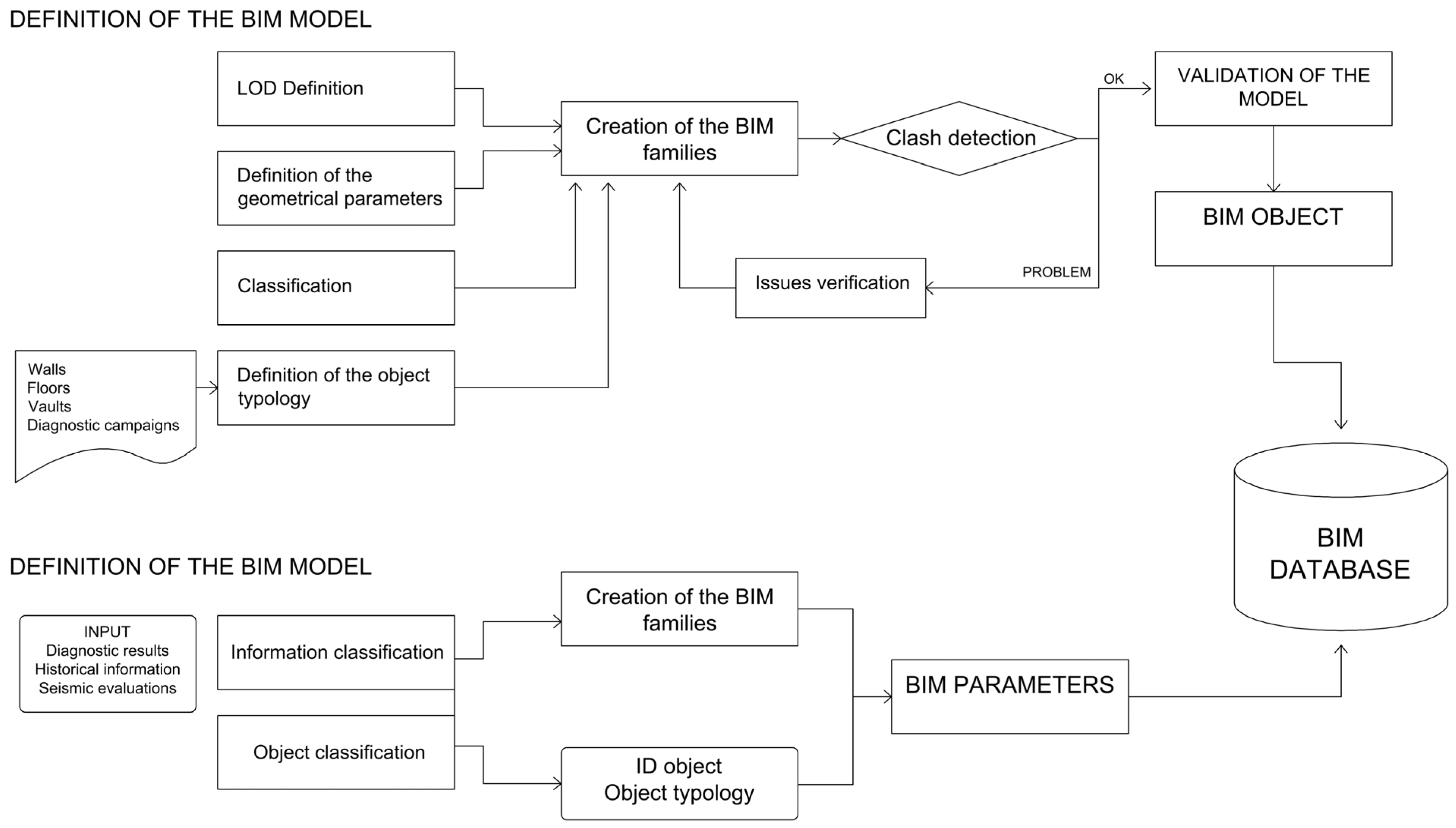
The proposed H-BIM workflow is not only aimed at representing the current state of the investigated structure, the so-called as-built model, but it is a methodology that can include other information related to the knowledge process aimed at the study of seismic vulnerability. The data collected during the cognitive analysis and verifications carried out on the CHB form a structured and dynamic organization within a complete geometric model. The model can be managed by inserting new data from research, surveys, and interventions, implementing the database connected to the virtual representation of the architecture. The database will be shared with the different figures involved in the process of study, management, and protection of the artifact. The workflow of the BIM methodology is shown in
Figure 1.
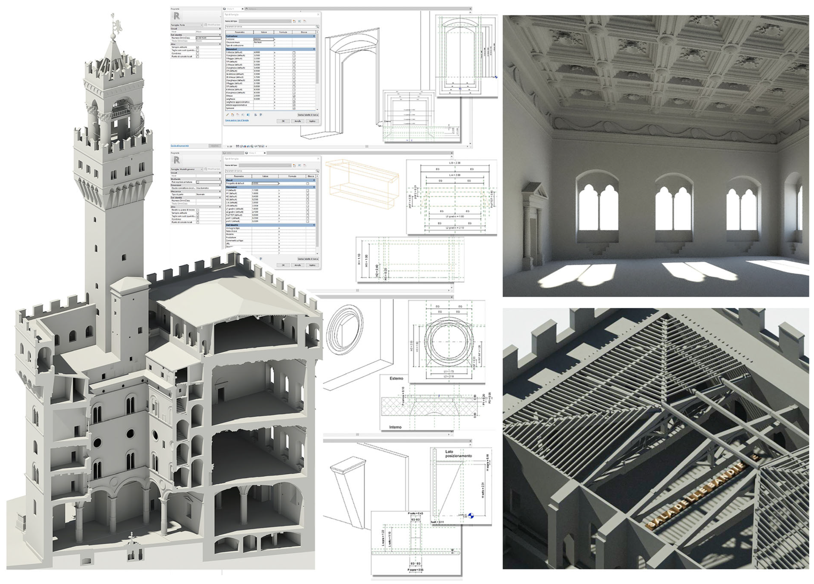
Modeling. The management of a historic building through “informative BIM models” presents difficulties related to the processing of the survey and the modeling of very complex and non-standard forms.
Within the proposed workflow, the modeling of the building follows the conventional methodology of parametric object modeling: each real object corresponds to its digital equivalent, whose parameters allow manipulation of its 3D geometric representation. Different numerical parameters and geometric constraints allow the geometry to adapt to different situations.
Information. For the digitization of the cognitive framework, the information component is central and is managed using parameters.
The information is defined and classified according to the corresponding architectural categories (walls, floors, vaults, windows, and decorative elements) and with the diagnostic and analysis categories through textual parameters and links to documents.
The information system defines a multidisciplinary 3D database able to describe in depth the cultural artifact and interrogate it.
Interrogation and management. The 3D model of the building is interoperable and can be queried. The flow of data managed by the parameters is displayed through a data sheet that can be exported using Excel tables, compiled by external users, and imported into the model. In model views, filters can be created to display information, as well as custom labels based on the parameter. Exporting the IFC model allows viewing and querying in open format and managing parameters in custom presets.
2.1. The Definition of the Parametric Modeling
Concerning the geometrical part, a laser scanner survey (LSS) is used for the architectural acquisitions. A scan-to-BIM workflow has been adopted for the realization of the parametric model. Several applications of scan-to-BIM procedures are available in the literature [
37,
38,
39].
The point clouds obtained through the LSS are faithful morphological and metrically correct reconstructions of reality. The 3D survey of the historical architecture makes it possible to obtain files in which information on shape and size are available simultaneously. The result of the digital survey consists of a point cloud that is brought to the BIM environment for the construction of the parametric three-dimensional model.
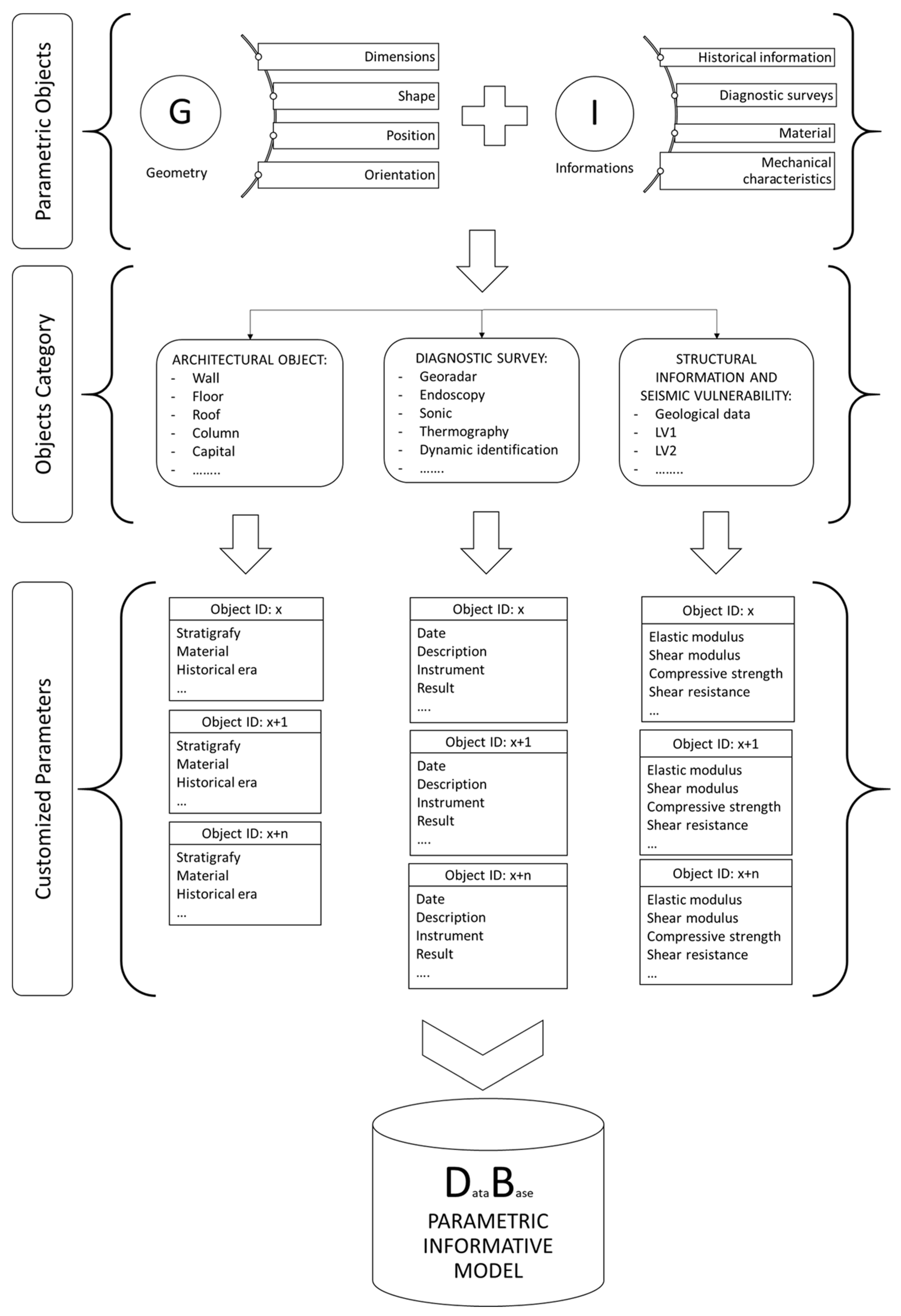
The lack of regularity and standardization that characterizes the historic building makes the modeling and parameterization phase particularly challenging. The parametric objects, however, are an aid to the modeling phase because of the possibility of defining those parameters several times, setting values for each case that allow the adaptation to each specific situation. The H-BIM approach allows the creation of personalized parametric objects characterized by a geometric component capable of providing information related to the shape, size and positioning of the object itself in the 3D space and in relation to the other elements, and an informative component capable of including heterogeneous information. In the case of existing constructions, we can refer to the historical period in which the element was originated, and apply this to data concerning the diagnostic phases and their results, the adopted materials, the stratigraphies and the mechanical characteristics of the elements investigated.
Within the proposed workflow, two types of objects functional to the construction of the model can be identified: the objects belonging to the category of architectural elements (walls, floors, vaults, windows, decorative elements), and the objects related to the insertion of data from studies and diagnostic campaigns.
First, it is appropriate to define the level of graphic and non-graphic detail (LOD) [
40] of the objects according to their use and purposes of the model.
For architectural elements, a faithful representation of reality must be achieved, avoiding the hyper-modeling of unnecessary details or into the hyper-parameterization of objects that become unmanageable. For these elements, during the modeling phase according to a reverse engineering process, the dimensions, morphology and materials of the building are analyzed, and the construction techniques are investigated. In this phase, the target of the H-BIM modeling should be borne in mind, together with the expected outcomes of the research once the model is obtained. The modeling of these elements is obtained through the system families and custom families with which parameters are associated and stratigraphies are defined, based on information from the diagnostic campaign.
The LOD of these elements is defined according to the purpose of the BIM model and the complexity of the object.
The objects of the diagnostic phase have fewer complex geometries; in general, a symbol or geometry is chosen that leads back to the type of investigation carried out. A simple geometric level, however, corresponds to an articulated information level that provides for the creation of specific parameters for the insertion of different types of information.
2.2. Protocol and Classification of the Information
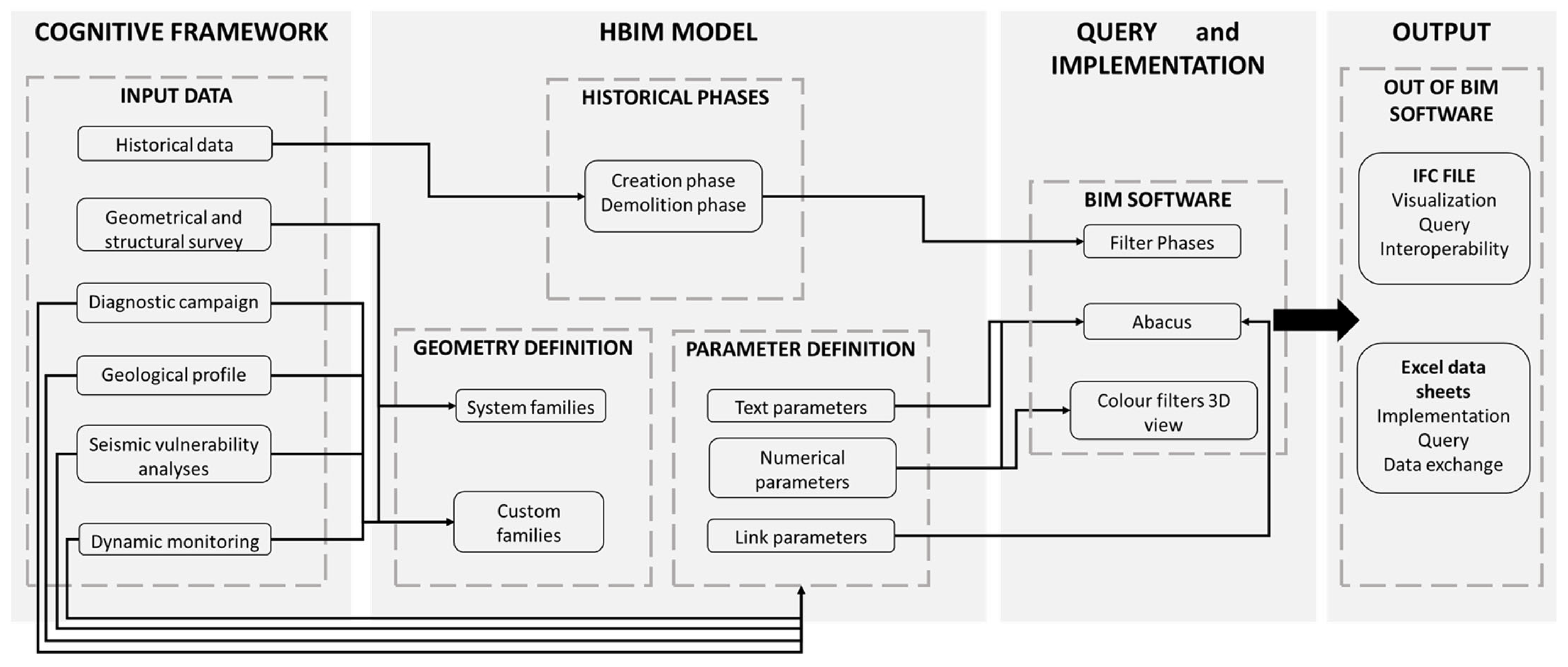
In
Figure 2, the workflow of the research is shown. The external sources from which the information comes are heterogeneous as they come from different disciplinary fields (2D drawings, point clouds, images, cards, notes, etc.). Data must therefore be organized to both to develop parametric geometric shapes and to generate information for the enrichment of the shapes themselves.
Data flow management is just as crucial as proper database structuring. The organization of the database should provide the definition of the structure of the “information tree” that hierarchically allows definition of the parameters to be associated with the objects of the model.
While for architectural and structural objects the system of families helps in the definition and insertion of information through already organized fields, for the categories of diagnostic campaign and seismic vulnerability the parameters have been created ad hoc according to the specific needs of users.
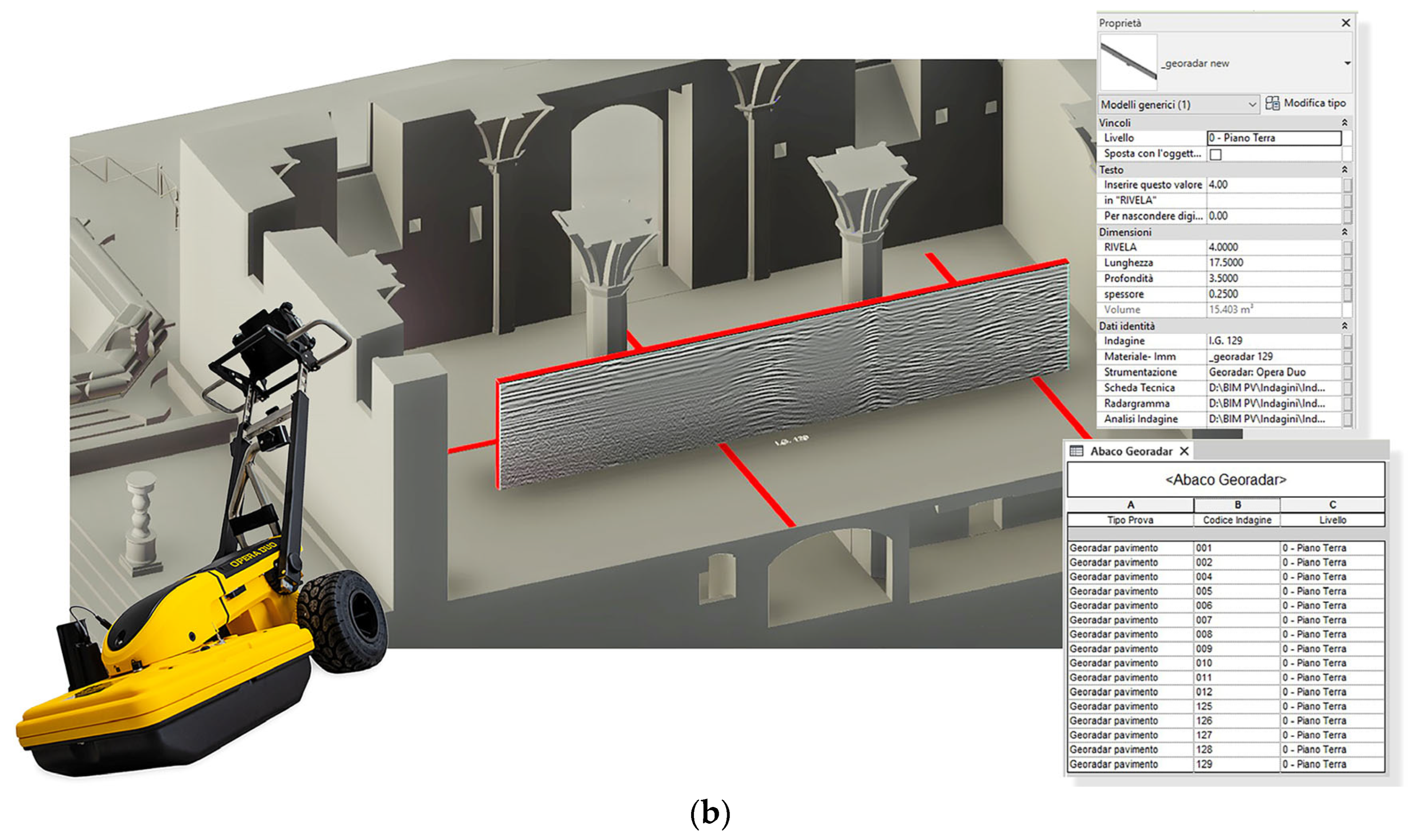
Each object has been equipped with an ID that univocally identifies each entity. Hence, single objects can be viewed through the appropriate label and within an abacus that allows the model to be queried. The default categories proposed by written programs do not always adapt to the needs of a CHB model, and the impossibility of creating new ones leads using present in the best possible way.
Therefore, working on the chosen categories and using shared parameters, at the level of family or types the parameters corresponding to characteristics common to a single type of survey were specified. The parameters assigned to the individual object (instance) are those that are specific to the individual survey. The choice of parameters to be inserted followed a logic that would allow an easy reading according to the rule of “what, where, how, when”. The investigated objects have therefore been associated with parameters that allow the user to enter information such as the date of execution, the description, the tool used and the results. In some types of investigations, for example GPR surveys, it was possible to create objects hosting the diagrams resulting from the instrumental processing in order to have a perfect correspondence between the geometry of the investigated element and any anomalies found. The advantage of this digitization procedure lies that it allows the exact geometric location of each investigation, permitting the identification of anomalies or structural discontinuities in relation to the context in which the survey was carried out.
The management and insertion of information relating to the levels of the seismic assessment can be made following the three levels of evaluations (LV1–LV2–LV3) provided by [
34]. It takes place through filing each investigated element associated with a specific object. In addition, through the management of the phases, it is possible to visualize the constructive evolution of the building and the subsequent interventions. In this sense, the conceived H-BIM process integrates the variable time through a multi-layer procedure. In the design of new buildings, the new dimensions of BIM can be extended up to 5D, 6D, 7D or 8D [
41]. Although in H-BIM optics, the building process is not so relevant, since the modeling of existing CHBs is rather oriented towards the conservation and documentation of the buildings, so the historical evolution of the existing structures becomes crucial [
42].
Therefore, within the H-BIM process, the knowledge of the historical evolution of the building is transferred through the organization of the model by phases. The phases describe and modify the interventions that took place in the different historical periods allowing a rapid visualization of the changes using filters.
2.3. Link-Oriented Procedure for Diagnostic and Seismic Assessment
During the phase of information enrichment, three types of parameters have been identified that can be used and connected to the object:
- -
text parameters;
- -
numerical parameters;
- -
link parameters.
The methodology proposed for archiving data from diagnostic campaigns is therefore based on the use of the first two categories for descriptive information or specific coefficients, and the third category for references to external documents.
Figure 3 shows the typical information flow used in projects. From the left, the input data define the geometries of new shapes using numerical parameters to flexibly adapt to different contexts. At the same time, the same data flow into the numerical, textual and link parameters, contributing to the information enrichment of the geometric shapes.
All these aspects contribute to the composition of a 3D multidisciplinary parametric database capable of describing the cultural artifact when interrogated both in the BIM software environment and outside.
The approach through specific parameters allows the user to insert the main information relating to the element to be cataloged. Generally, this information concerns the location, the date of the test, or the type of test and instrument. The link-oriented approach, on the other hand, allows the user to attach to objects a multiplicity of information that would be difficult to insert within a parameter. Therefore, the possibility of drawing up and linking the model to updatable cards is a very useful procedure.
Among the elements that provide for the insertion of a file there are mainly diagnostic investigations for which the card is attached via URL to an external file. The assessment of seismic vulnerability is also organized through descriptive cards of the behavior of each considered system; e.g., for LV1 and LV3, which require a global evaluation of the structures, the descriptive sheets are related to the classification in terms of structural units. For LV2, as it regards the kinematic assessment, the different indexes could be directly linked to the considered macroelements.
URL links can also include references to pages on websites. This is the case for dynamic monitoring data for which the resulting graphs can be plotted on a web page and displayed in real time directly from the model.
2.4. Output and Query Management
Database consultation in BIM software can be achieved through schedules and 3D views.
The flow of managed data is displayed through schedules of elements; in the model view it is possible to create filters to display the information, as well as customized labels based on the parameter. Each object presented in the model, being equipped with an ID, can be identified within an abacus that allows the model to be queried.
The data cataloged in the schedules can be exported via Excel tables, filled in by external users and imported back into the model.
3D views are another useful element allowing the user to select objects and view their properties. By creating color filters for some parameters that have numerical values, it is possible to associate a color to the value that the object will assume when creating the color maps.
Interoperability and collaboration between different disciplines may be guaranteed by exporting in IFC format, although there are current limits of this standard with respect to the information collected in H-BIM [
43]. Exporting the IFC model allows viewing and querying in an open format. The management of the parameters in customized presets allows consultation of the model without using the proprietary format.
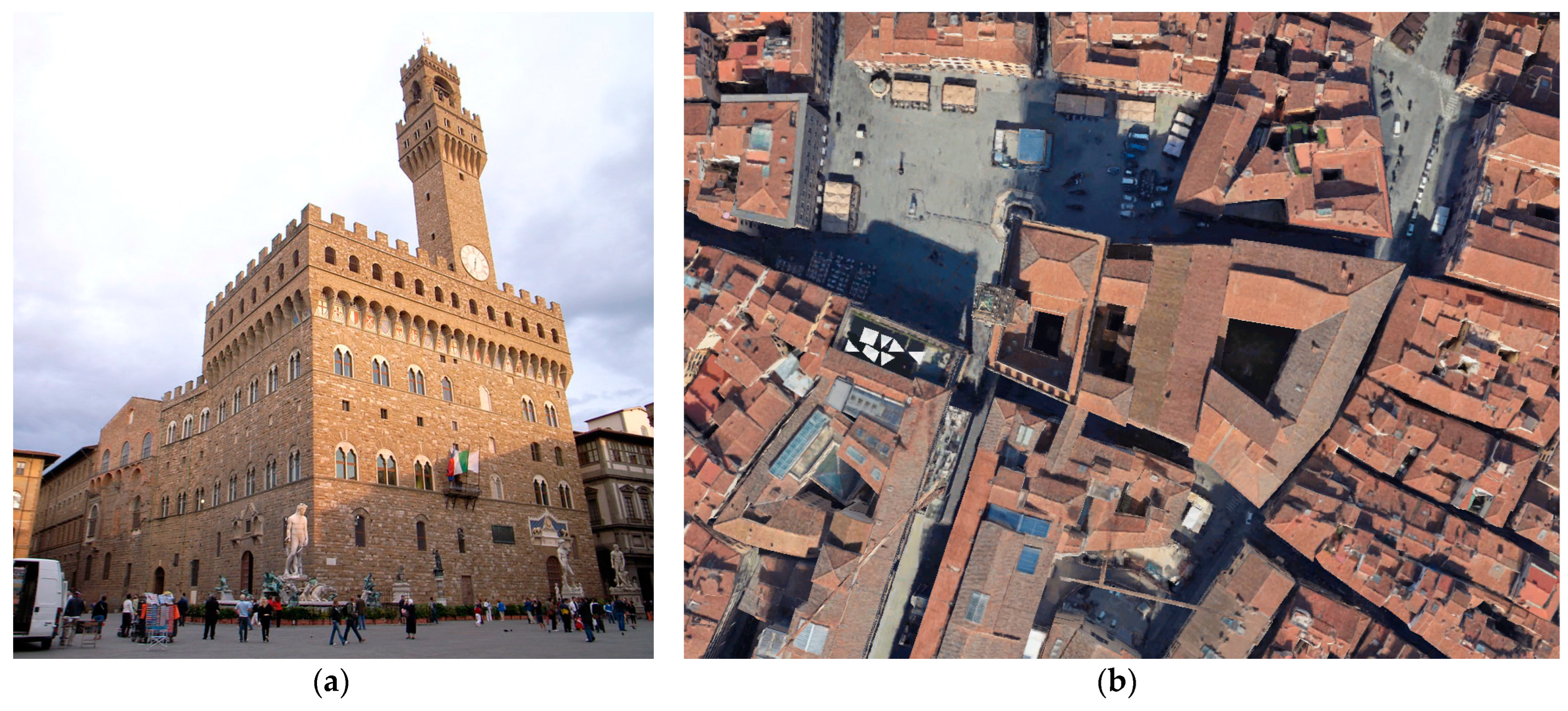
3. “Palazzo dei Priori” in Palazzo Vecchio: An Historical Case
Palazzo Vecchio is one of the most famous monuments of Firenze (Italy). It is located in Piazza della Signoria, an historical area located at the southern boundary of the first Roman city in the territory. The site where Palazzo Vecchio stands is an extremely rich place from historical-archaeological perspective; the present-day street datum is about 6 m above the Roman street datum [
44,
45,
46]. During the Roman period, when the city of Florence was founded, the area of Palazzo Vecchio was located outside the town walls, close to the south-west corner of the original castrum [
47]. Here, a Roman theater existed for several centuries, and its traces are still visible in the underground level of Palazzo Vecchio. The building founds its origins in the early fourteenth century, when the famous architect Arnolfo di Cambio built the first nucleus of the palace as the seat of the city government. Through different historical moments and political successions, the building has maintained its political vocation over the centuries. Palazzo Vecchio is actually the seat of the Municipality of Florence, which counts over 382,000 inhabitants and it is the administrative center of a metropolitan area of 1 million citizens. For its history and unicity, Palazzo Vecchio is included within the CHBs of the city; as the entire historic center of Firenze, the structure has been under UNESCO patronage since 1982. Many authors dealt with the historical evolution of Palazzo Vecchio, which is constituted by several structural units erected during the centuries [
48,
49,
50,
51,
52,
53,
54,
55,
56,
57,
58]. A view of the main façade of the palace and an urban overview are shown in
Figure 4.
3.1. The Cognitive Framework
The Arnolfo’s Tower, as the other part of Palazzo Vecchio, are part of a protocol signed between the Municipality of Florence and the University of Florence for the seismic risk assessment of the monument. For this reason, several investigations have been carried out. The knowledge path recommended by national and international standards has been applied; it included a research study on the modifications and alterations of the building through the centuries, a laser scanner survey, and the execution of non-destructive (ND) and minor destructive campaigns (MD).
3.1.1. Historical Evolution
Palazzo dei Priori predominates as the oldest building within the urban aggregate of Palazzo Vecchio. Its design is attributed to the medieval architect Arnolfo di Cambio, who worked on it from 1299 to 1302. The building was built over ancient Roman traces and incorporated medieval buildings. The palace was built to host the main politic and administrative figures of the Republic. The construction of Palagio dei Priori during the Florentine Republic represents the starting point of a period of many urban and building activities. According to Frey [
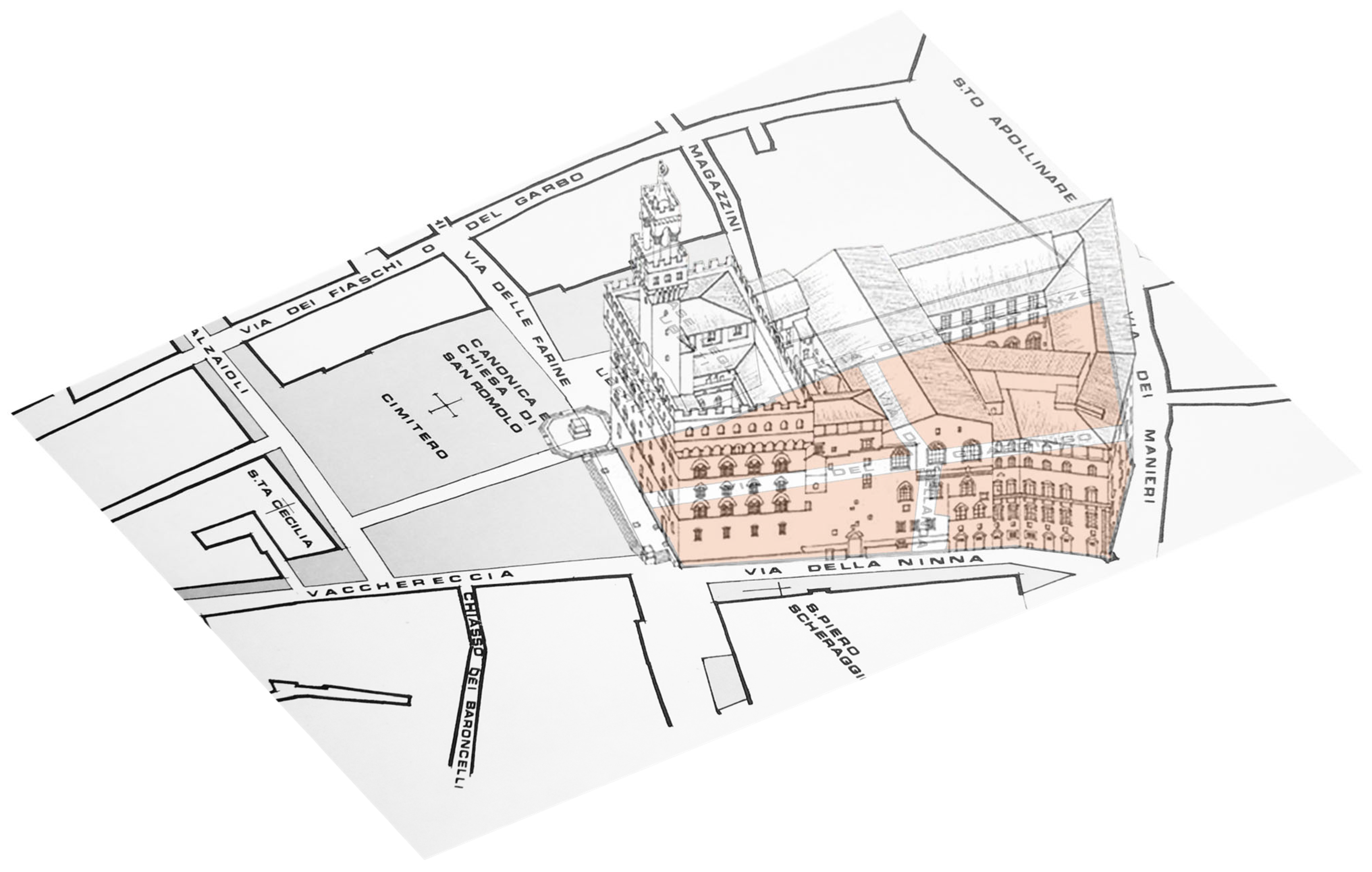
49], the area occupied by Palazzo Vecchio in the fourteenth century represented an articulated and complex urban reality, subdivided within three different medieval streets: via di Bellanda, via dei Manieri, and via dei Guardingo (
Figure 5).
The building conceived by Arnolfo Di Cambio was divided in two main parts. In the northern area were the major rooms: the Armory at the ground floor (Sala D’Armi), the Salone dei Dugento on the first floor and the Sala Grande on the second floor. In the southern area, the administrative spaces were located around an inner courtyard, the so-called Cortile di Michelozzo, incorporating the pre-existing Torre dei Foraboschi within the building façade. Regarding the Torre dei Foraboschi, the basement of this structure was used to realize the new termination of the actual Torre di Arnolfo, overwhelming the palace. According to Vasari, the lower levels of the Foraboschi tower were filled with construction materials to provide a solid basement for the new elevation. The Tower surmounted the roof of the palace and became the tallest tower in Florence and the second highest building after the Brunelleschi’s Cupola.
Further interventions occurred during the Duca di Atene period, with the building of the adjacent structures reconnecting Palagio dei Priori with the structures facing via dei Manieri. Between 1300 and 1356, the Florentine Republic bought a series of properties in the areas encompassing the Palazzo Vecchio. These buildings were initially annexed to the administrative structures without major interventions, preserving the existing structures. Later, a series of renovations targeted at significant alterations of the state of the building started with the Duca di Atene period. The current Palazzo Vecchio the sum of a series of architectural renovations that continued during the Signoria of Cosimo I and his successors, the Grand Dukes Francesco and Ferdinando until the alterations during the nineteenth century when Florence was selected as the capital of Italy. Important architects worked at the renovations of Palazzo Vecchio during the centuries. Regarding the oldest parts, significant interventions were planned during the Cosimo dei Medici period under the supervision of the architect Michelozzo. They involved alterations to different parts, such as the inner staircases and the pillars of the courtyard. Other changes to the Palagio dei Priori occurred in 1472, when the Sala Grande over the Salone de Dugento was divided by a massive wall. Although the panel was laid over a wooden structure, the architect Giuliano da Maiano conceived a structural system hiding an arch inside the walls, connecting it with the beams under the wall through iron tie rods [
60]. In the sixteenth century Giorgio Vasari was called on to renovate inner parts of the palace. In 1561 he finished the project of the stairwells connecting the Cortile della Dogana with the Sala Grande of Palazzo dei Priori. Then, he continued to design new quarters inside the palace, such as the rooms of the Eleonora. From the seventeenth century, the building stopped hosting the residential functions of the court, as they were relocated to the Palazzo Pitti. During the following centuries, different political realities alternated their supremacy. In the beginning of the nineteenth century, several restorations were carried out, promoted by different architects (Giuseppe Del Rosso and Giuseppe Martelli). During the time Florence was the capital of Italy, other renovations were designed by the engineer Carlo Falconieri. The palace became officially the city hall of Florence in 1872. During the twentieth century the palace underwent different restorations involving different parts of the complex. A recent intervention has been finally completed in the beginning of the twenty-first century following the design of Sisto Mastrodicasa. He devised a way to strengthen the upper part of the Palazzo dei Priori, involving the upper gallery and the merlon of the medieval structure.
3.1.2. The Geometrical Survey
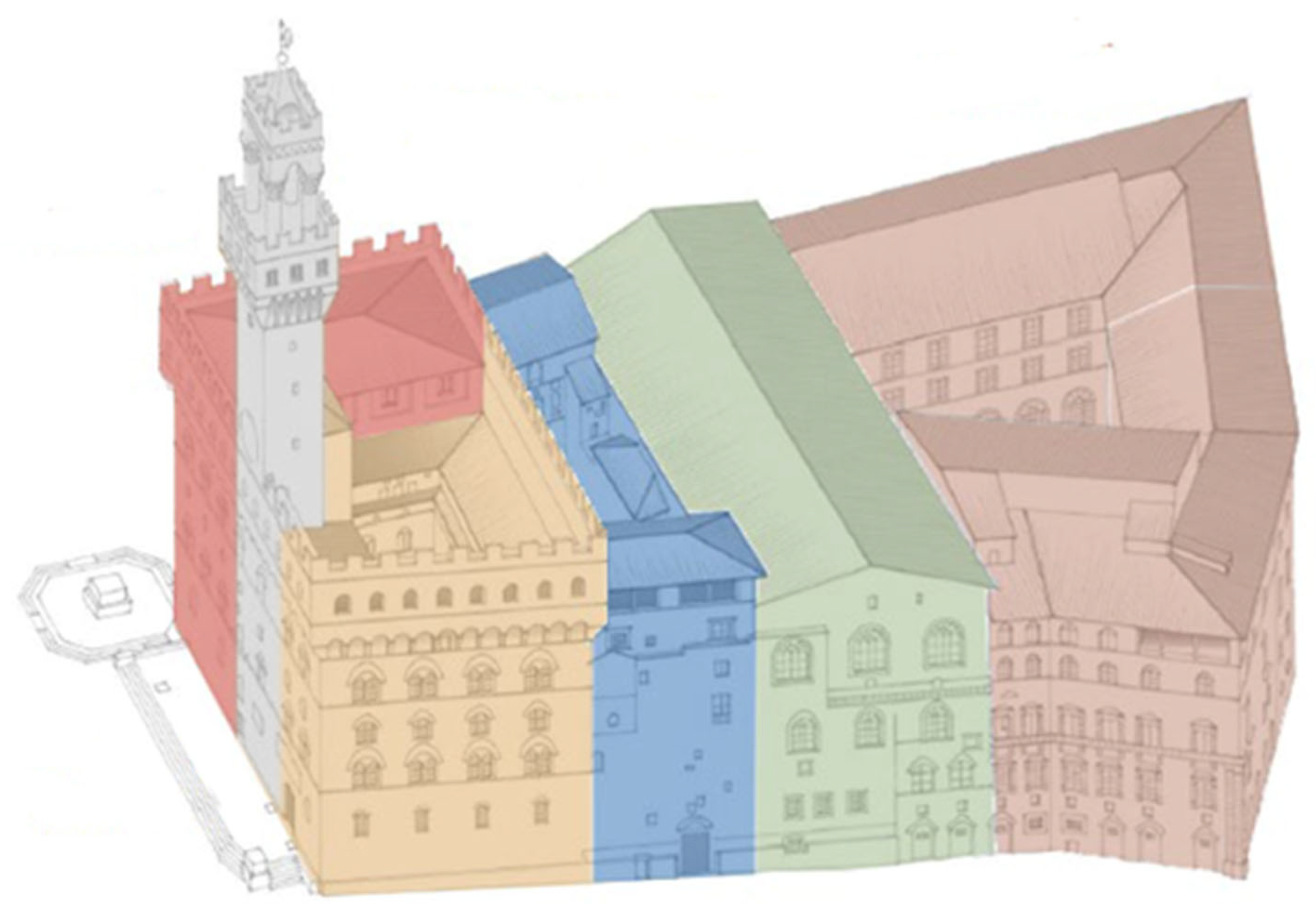
The 3D geometry of the complex has been realized on the base of a recent LSS. The LSS was carried out over several days with contemporary different scanners. It allowed the complete geometrical characterization of the building, from the underground level (where traces of the Roman amphitheater are still visible) up to the top of the Arnolfo’s Tower. In
Figure 6, a representation of the different structural units considered for Palazzo Vecchio is shown. The structural classification has been made on the basis of the architectural and structural characteristics of the building, also accounting for previous historical research [
58].
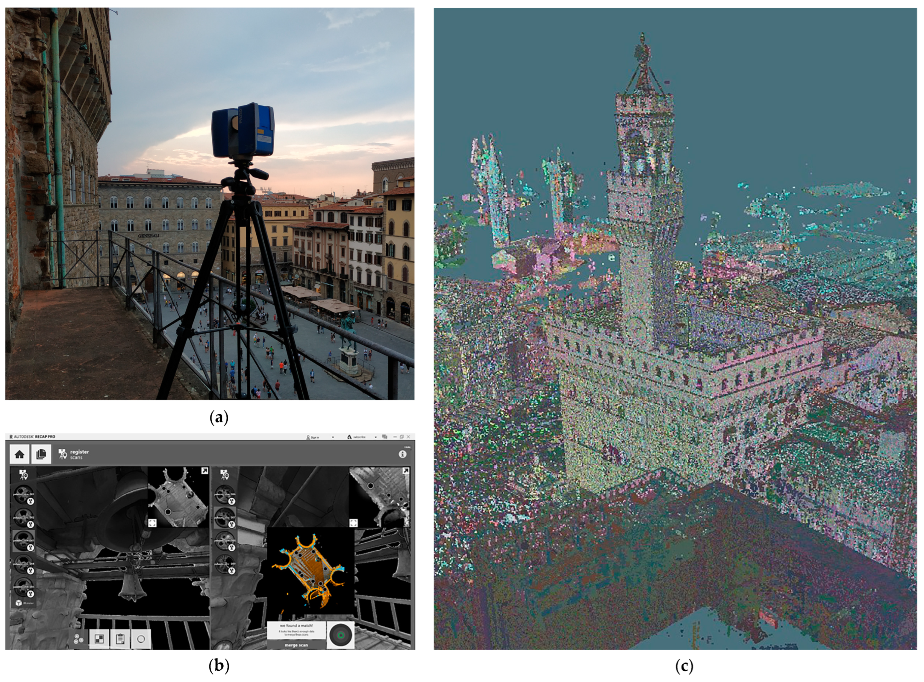
The LSS was executed to acquire the morphological and architectural aspects of the whole urban aggregate (
Figure 7). The procedure was divided into two main phases: the acquisition of the geometrical information and the elaboration of data and their restitution. The survey used a number of relevant instruments, often at the same time through the work of several operators. Because of the exceptional dimensions of the palace, the survey started in July 2019 and ending only in 2021. The complete number of scans is of the order of 5500 registrations.
Table 1 lists the different instruments adopted for the campaign, together with their main characteristics [
61].
Later, the point cloud generated from the different scans was processed in Autodesk ReCap Pro. The point cloud was adopted to elaborate graphic 2Dand 3D contents. Furthermore, it represented the basis for the following parametric modeling.
As part of the LSS phase, a survey of the crack patterns of the building was executed. This phase was targeted at pointing out possible damage in the building, and to identify disconnections within the different structural units of the complex. Although some historical cases of subsidence of the underlaying soils caused movements in the past centuries, the current results showed physiological crack patterns that are coherent with the historical developments of the construction.
3.1.3. The Diagnostic Campaign
The diagnostic campaign involved ND and MD destructive techniques. The combination of the different results then created information on the mechanical characteristics of the materials able to reconnect masonry walls to the classification provided [
62]. In this work, a hierarchical procedure has been followed, targeted at classifying the structural features of the palace while limiting the effects due to the execution of the diagnostic campaign. Initially, ND tests were conducted extensively in order to identify the structural consistency of the building in the elevation with reference to the horizontal elements. Then, MD tests (such as drilling tests and endoscopy investigations of the inner parts of masonry structures) were conducted to validate the hypotheses made (
Figure 8).
The adopted non-destructive techniques used were:
- -
thermography campaign, targeted at the identification of the masonry textures and the individuation of non-homogeneous parts;
- -
GPR surveys, able to detect discontinuities within the investigated materials (subsoil and structures);
- -
sonic tests, adopted to analyze the density of the masonry and the presence of holes as qualitative judgments on the mortar state and the constructive elements.
The MD techniques were:
- -
Plaster removal for the evaluation of the masonry texture; in the case of Palazzo dei Priori the research took advantage of restoration interventions that were ongoing during the diagnostic campaign acquisitions;
- -
Drilling campaigns with video endoscopy targeted at investigating the internal composition and the state of conservation of the constituent materials; this research was carried out limiting the number of holes to the existing structure by extending the validation of the visual test according to the classifications carried out implementing the ND phases.
If other ND tests are available (such as penetration tests on the mortar or sclerometric tests for the definition of the compressive strength of the resistant elements of the masonry walls), they could be implemented in the H-BIM procedure as well. The application of investigation techniques from the first category has made it possible to obtain information on construction techniques, masonry textures, the presence of hidden elements, and initial estimates of the resistance of the elements. The execution of second category investigations in a second phase made it possible to calibrate the results of the non-invasive investigations, arriving at a qualitative judgment on the various elements of the structural system. A comprehensive description of the test carried out can be found in [
63].
In addition to these experimental surveys, dynamic monitoring of the building has begun through the structural health monitoring of the Arnolfo’s Tower [
64]. This has been executed through the disposition of tri-axial velocimeters along the height of the construction. The structural monitoring has firstly obtained the main frequency of the construction, together with highlighting the variability from environmental factors. Although the monitoring will come under further research (e.g., calibration of numerical models for more refined seismic analysis) the outcomes of the work have been implemented in the H-BIM as the collector of the different investigations on the building.
The results were compared with the evidence coming from the historical analysis and the geometric survey, in order to identify the structures belonging to the various eras. The research was targeted at classifying the structural elements according to listed typologies. The slabs and vaults have been listed according to their structural consistency. The masonry walls have been classified following two distinct tables, the regional one provided by [
65] and the national one provided by [
62]. The final typology identification combines the two tables. Specifically, each masonry typology has been related to an alphanumerical ID. For each masonry typologies, the following relationships have been derived:
A1—Masonry with an inner nucleus and two external leaves built with variable stones, badly disposed and without a connection between the two sides of the panel/Rubble stone masonry;
C2—Rough stone masonry with irregularities/Rough-block masonry with non-homogeneous thickness of the external faces;
B3—Masonry with an inner nucleus and two external leaves built with stones of regular dimensions, well-disposed and with connections between the two sides of the panel, horizontal layers of chiseled stones or clay bricks/Split stones masonry with good texture disposition;
L-7—Full or semi-full clay masonry/Clay bricks and lime mortar masonry;
G5—One-leaf masonry made by blocks of tuff of chiseled stones with constant dimensions/Regular block masonry made of soft stone (tuff, calcarenite, etc.)
where the first definition refers to [
65] and the second one to [
62]. A more comprehensive description of the cross relationships used to determine the masonry typologies of the bearing walls based on ND and MD campaigns can be found in [
63]. Hence, the structural characterization of the model can be obtained. This information has been adopted to produce thematic maps of the building, then, the different classifications have been listed within the H-BIM database.
3.1.4. The Geology Investigation
Florence is built on an alluvial plane, whose subsoil has been intensely studied in the last twenty years [
66,
67]. In the area of Palazzo Vecchio there are three drill-holes that, in connection to the archaeological excavation data [
44,
45,
46], clarify the subsoil setting in the area surrounding the Arnolfo’s Tower.
The shale bedrock lies about 10–14 m below the present-day street datum; over the bedrock there are about 8 m of poorly sorted gravels (GP) and above that, a couple of meters of well sorted sands (SW). The archaeological layer (Ar) is around 6 m.
Foundation data are available from archaeological surveys in the surrounding area and due to the exploration deep underground adjacent to the tower, which reaches the Roman datum 6 m below the present-day street datum, clearly shows that the Foraboschi tower is rooted onto Roman walls. In turn, the Roman edifices have the base of their foundations about 2 m below, rooted into the gravel. Geotechnical and wave velocity (V
p and V
s) data are available by down-hole, lab analysis and by [
67] (
Table 2).
Although this information is not directly referred to the building, it has been considered in the research framework in order to account for the soil stratigraphies of the building. These data are used in the definition of the seismic hazard of the area, and they are still the basis of further phases of the work considering settlement or soil-structure interactions [
68,
69,
70].
3.2. H-BIM Modeling and Database
The BIM model of the Palagio dei Priori was created starting from the point cloud which in Autodesk Revit is used as a morphological-dimensional guide, and from information from history and diagnostics.
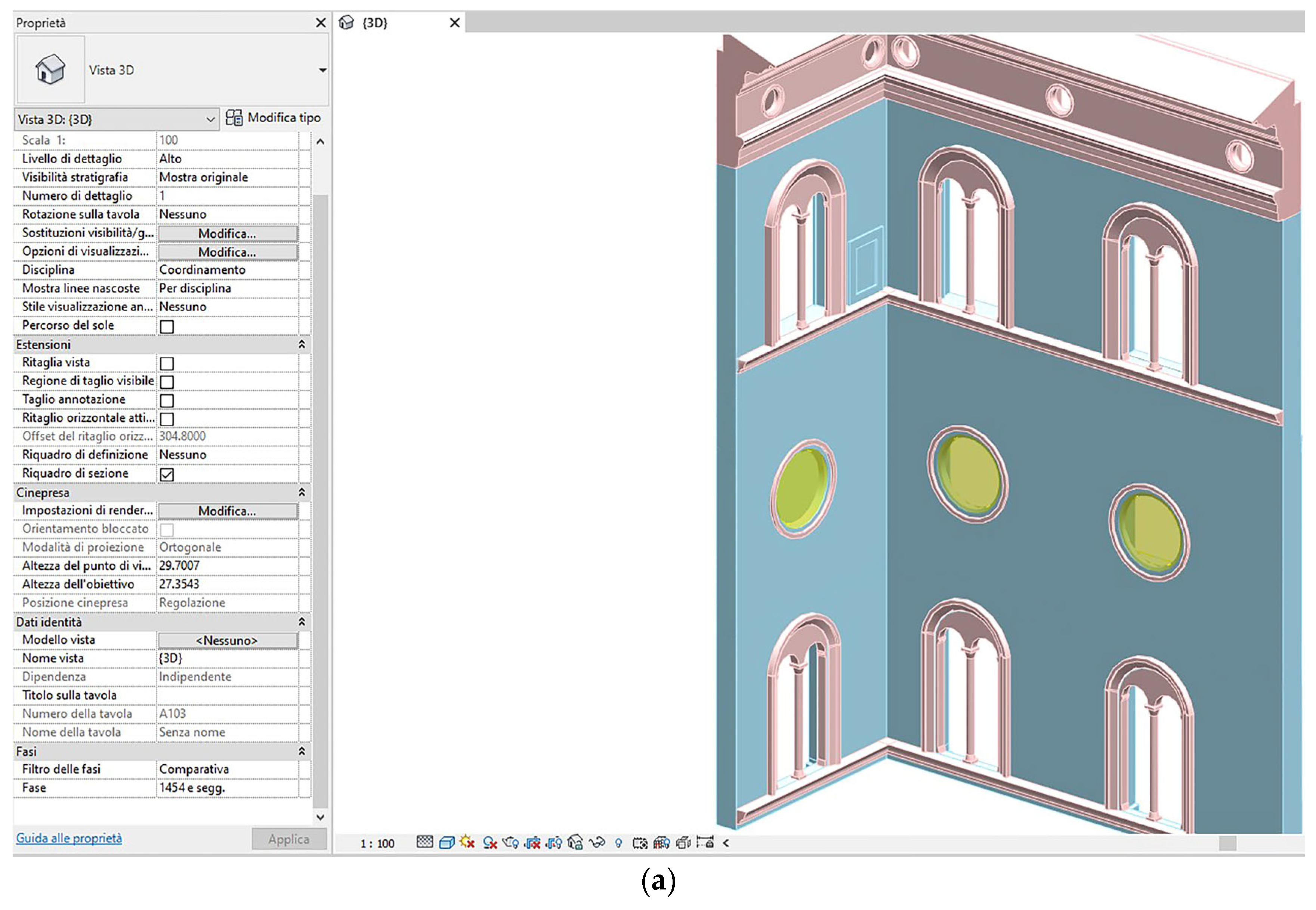
In the modeling environment, the simultaneous use of different views (plans, sections and elevation sections) allows the user to have control and work from the point cloud. The architectural objects were modeled using system families (walls, slabs, roofs) or loadable families for decorative elements, while specific custom families were created for the diagnostic and seismic vulnerability object categories. Furthermore, the use of adaptive families has allowed the overcoming of geometric difficulties linked to the presence of unique and irregular shapes.
The results can be framed in a LOD 300: the elements are represented in terms of size, morphology, correct position, and orientation, and it is possible to connect non-graphical data (
Figure 9). The geometric data are directly measurable on the model, which can be interrogated and has the capacity to contain a large amount of information.
The creation of the information content starts with the information of the historical-critical analysis, the geometric-structural survey, the crack pattern, and the diagnostic test campaign. As already seen in
Figure 10, this information was partially used during the modeling phase for a structurally coherent construction of the model. Through BIM methodology, the considerable amount of data coming from the knowledge path can have been precisely organized and managed.
The information content included in the model can be classified as follows:
- -
Historical data;
- -
Data from the structural survey: construction characteristics of the structures, crack pattern, etc.;
- -
Diagnostic campaign data: non-destructive or minor partial destructive investigations, data from dynamic monitoring;
- -
Data about geological structure of the area;
- -
Results of seismic vulnerability analyses.
In general, an intelligent object was created for each category and parameterized with dimensional rules for correct adaptation to local needs. These families have been equipped with shared parameters that are used to generate schedules in which the information content is entered and filtered as needed, thus speeding up the modification process. For system families, information can be entered using the default fields (example: “Comments”) or by creating new ones.
The evolutive phases were chosen and divided based on the interventions that have taken place over the centuries (
Figure 10a). The phases are ordered from the most distant in time (Phase 1) to the most recent (Phase n + 1). An object in a phase can exist in one of these four states: existing, new, demolished, or temporary. In “graphic replacement” it is decided which colour to assign to each state, and therefore to the objects that will fall under that specific condition. The phase of creation and the phase of demolition have been assigned to each element.
The data relating to the structural survey were entered mainly through the stratigraphies of the objects, the geometric shape, and the materials (and in some cases with customized families such as for the cracks). The “crack” object provides a family for the cracks of the ceilings and floors, and one for the fractures of the vertical structures with parameters such as level, typology and location, texts, and photographs.
In the diagnostic campaign, for each type of test, a personalized parametric family was prepared in which the geometry of the object has the characteristics of the test itself and which has been placed in the exact place where the investigation was performed. In this way there is also the possibility of being able to quickly compare the results of the different tests carried out on the same structure. In
Figure 10b, an example for the GPR investigations is shown.
All families include parameters such as the type of test, the investigation code, the execution date, the equipment used, and the link to the data sheet.
Because of the schedules it is possible to consult the unified framework of the investigations that have involved the palace and are closely connected with the model. The results of the diagnostic survey, merged into the characterization of walls and floors and used in the modeling phases of the main elements, are entered into the model using the parameters made available by the software.
The insertion of geological data in a three-dimensional environment has made it possible to instantly visualize the relationships between the subsoil structure of the area and the building. The geological stratigraphy has been modeled by assigning the relative characteristics.
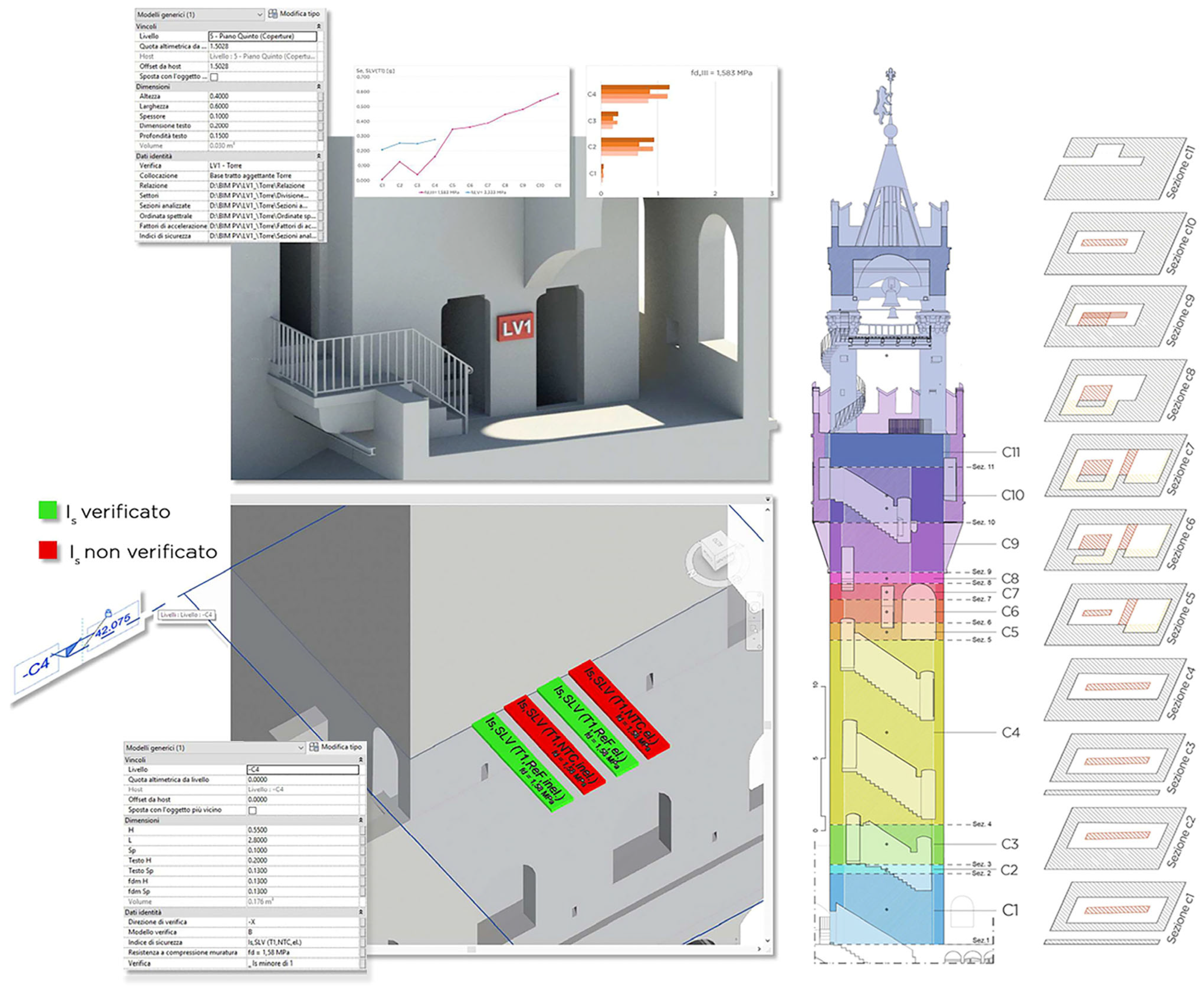
The data processed during the seismic safety analysis of the Arnolfo’s Tower were linked to the model using a customized parametric family. The parametric object allowed access to the information collected on the evaluation of the seismic action and those deriving from the seismic evaluation. More information on the conducted seismic analyses is given in the following section.
3.3. Simplified Seismic Risk Analysis
For the seismic risk assessment, a simplified procedure was adopted. The Guidelines for the Evaluation and Reduction of Seismic Risk of Cultural Heritage [
34] give the procedures for the assessment of CHBs in the Italian territory. Herein, three different levels of evaluations are defined. The first level (LV1) constitutes a territorial level and is targeted at a rapid assessment of the risk affecting the building. The methodology is based on geometrical and structural parameters indicating vulnerability and risk classes. The second level of evaluation (LV2) is achieved by the execution of kinematic analysis for the assessment of the local effects that can occur in seismic events in case of poorly connected structures. Finally, the third level (LV3) is targeted at investigating the global behavior of the structure. In this work only the first level, based on the geometrical and structural features of the building, has been applied. Further studies are ongoing in order to develop in-depth investigations on the structural performance of the building.
The first level of evaluation (LV1) is based on simplified procedures. Four distinct models are available (tower, bridge, church and palace) divided according to recurrent structural behavior during seismic actions. In this work, the simplified approach was realized by exporting the structural information available in the H-BIM database. Due to the parsimonious requirements of the structural procedure, the information from the H-BIM model was sufficient to compute the seismic performances of the structure. The palace model has been used for two main units of the palace: the unit of the Sala D’Armi and the one around the Michelozzo’s Courtyard; hence, the tower model has been adopted to investigate the Arnolfo’s Tower. The two methodologies consider simplified mechanical approaches based on the verification of performance capacities. Both models consider a comparison in terms of accelerations between capacity and demand. For the palace model, the capacity was computed considering the shear resistance of the building, while the tower model involved the combined bending and axial force of the different resisting sections of the bearing system. In both models, a confident factor FC equal to 1.15 and computed according to [
34] was used. The mechanical properties of the masonry walls were assumed on the basis of the classification provided by [
62] considering the structural classification reported in
Section 3.1.3. The seismic demand was based on the seismic hazard of the city of Florence and a soil class B, assuming a nominal life of the existing structure equal to 50 years and a building class III.
Table 3 shows the results of the simplified approach obtained for the two units according to the palace model. For each level, the shear resistance of the building
with the involved resistant area A
xi,yi are reported. The comparison between the capacity of the building, and the correspondent elastic spectrum of the seismic demand gives the safety indexes of the units. In this case, the values of 0.35 for the Michelozzo’s Courtyard and 0.17 for the Sala D’Armi have been obtained.
These values highlight some critical issues regarding the performances of the two units; although since we are referring to existing structures, the obtained values are significantly lower than 0.60, which is the value commonly accepted for non-designed buildings. However, the obtained indexes are the first results of a simplified approach that assumes listed mechanical parameters according to a national table. In the authors’ opinion, in further analyses the mechanical values could be improved on the basis of the ND tests executed (which proved the good quality of the masonry walls), together with the possible calibrations of numerical models conducted after the dynamic identification of the whole building. For the Arnolfo’s Tower, the simplified calculation model proposed by the guidelines has been adopted. The structural element tower is considered as a cantilever subjected to a system of horizontal forces which can fail by crushing in the compressed zone in a generic section.
For very high structures of high geometric complexity, the analysis is typically very sensitive to the strength parameters adopted. Therefore, two distinct compressive strength values for the masonry walls of the Arnolfo’s Tower have been assumed, in order to consider a plausible range of safety indexes in absence of more refined investigations. The seismic verifications have been made for each different section along the height of the Arnolfo’s Tower. Considering the most stressed sections of the element, the results point out that the verifications are always satisfied when assuming compressive strength values around 3.33 MPa, while some safety indexes decrease to values lower than 0.10 for compressive strength values of 1.58 MPa. These values are the ones coming from Table C8.5.I of [
62] considering alternatively the compressive values from rough-block masonry with non-homogeneous thickness of the external faces masonry typology or for the stone squared-blocks masonry, assuming the maximum values of the range with the confidence factor of the material equal to 2.4.
In
Figure 11, examples of the process of cataloging data into the H-BIM of Palazzo dei Priori are shown. The objects representing the Safety Index are editable labels. The figure shows two parameterized texts: the first shows the name of the verification index relating to the aforementioned assumptions on the compressive strength. The material changes its colour based on the two conditions: Is < 1 and Is ≥ 1. The family also contains the parameters relating to the verification direction and the chosen model. The digitalization process is ready to be implemented with the following results coming from the kinematic assessments or global numerical evaluations.
As already mentioned, a dynamic identification of the palace is one of the targets of the research. To this aim, dynamic monitoring data have already been considered in the three-dimensional model. This was achieved by modeling the stations as loadable parametric families to which information identifying the object, the date of placement, and its location is linked. The images relating to the hourly average spectra and the waveforms on the three components are also inserted via URL. The next step is a system that will allow real-time observation of the state of the Arnolfo’s Tower. The connection to the model will take place via a URL inserted in the specific parameter of the modeled family, which will give access to an online environment where the vibrations recorded by the seismographic stations will be shown instant by instant and which will therefore allow continuous monitoring of the structure. A Risk-Based Early Warning System capable of launching automatic alarms will also signal the cases in which certain pre-set thresholds are exceeded [
71].
4. Conclusions
In this paper a H-BIM workflow for the identification and collecting of the structural features of historical CHB is presented. The research considers the oldest part of the monumental aggregate of Palazzo Vecchio, in Florence.
The research conceives a H-BIM protocol oriented toward the identification and classification of existing CHBs in structural perspective. The proposed workflow takes place within a series of contributions targeted at obtaining structural models from H-BIM models [
12,
13,
14,
26,
29,
30,
31,
32,
33]. In this context, the parametric modeling is specifically focused at determine the structural parameters of the construction, avoiding problems related to excessive details related to different issues or too detailed models [
33]. Once the parametric objects are created, information on the executed campaigns can be listed inside the three-dimensional database. The application to the case study shows the effort in realizing a LOD300 model of an historical building while involving issues coming from interdisciplinary researches. Compared with other cases available in literature, LOD300 represents an accurate level suitable for the structural analyses of the investigated buildings [
28]. However, specific simplifications in structural perspective may be necessary depending on the conducted structural analyses. The following points can be made:
- -
The realization of a global parametric model of the building permits easy transfer of the acquired information, defining a model which is suitable during all phases of the construction’s cycle;
- -
The link-oriented procedure has allowed filling the database with information coming from different areas, guaranteeing a univocal document for the management of the monument;
- -
The LV1 seismic assessment has permitted a suitable and rapid transfer of the information from BIM to spreadsheets in order to execute the computations.
If the H-BIM protocol has produced a documental database involving the architectural and structural features of the building, it is still at the basis of the information transfer for different needs. H-BIM environments are capable tools able to collect multidisciplinary sources into a unique 3D environment with respect to a significant building, whose dimensions are around 50,000 m
3. Concerning the structural assessment, the LV1 approach has only required the transmission of the structural information of walls and slabs together with their geometry, however, 3-D transfer through IFC modules are expected for the following phases of numerical analyses. The geometrical and structural information will be imported into numerical environments following different approaches, such as finite-element and equivalent frame [
28,
72]. For the different approaches, the analyses critically investigate the level of information automatically transferred, in order to reduce errors minimizing the human actions needed. The different analyses will allow the development of more refined analyses, concerning both the whole palace and specific portions. The outcomes of the dynamic monitoring of the building will help in the calibration of reliable structural models through linear modal analysis, while the performance of the structural will be investigated via nonlinear static and dynamic analyses.
The H-BIM model of Palazzo Vecchio can be adopted for several purposes involving its facility management, the proposal of strengthening interventions, the update of museal paths, or firefighting plans [
73,
74]. Last but not least, these informative models can be used not only by administrators and managers, but also for academic and didactic purposes for citizens and tourists through virtual 3D tours and augmented reality explorations [
75].


 ,
, 


