Article

Tensile Behavior of Titanium-Clad Bimetallic Steel Butt-Welded Joints

1
State Key Laboratory of Metal Material for Marine Equipment and Application, Anshan 114009, China
2
Ansteel Beijing Research Institute Co., Ltd., Beijing 102209, China
3
Department of Civil Engineering, Tsinghua University, Beijing 100084, China
4
Key Laboratory of Civil Engineering Safety and Durability of China Education Ministry, Tsinghua University, Beijing 100084, China
*
Author to whom correspondence should be addressed.
Buildings 2023, 13(4), 912; https://doi.org/10.3390/buildings13040912
Submission received: 27 February 2023 / Revised: 29 March 2023 / Accepted: 29 March 2023 / Published: 30 March 2023
(This article belongs to the Special Issue High Performance Steel Structures)

Abstract

:
Because of the promising corrosion resistance and load-bearing capacity, titanium-clad (TC) bimetallic steel has gained increasing attention in ocean/coastal civil and structural engineering. Due to the double-layer nature of TC bimetallic steel, the characteristics of the structural member’s geometry and weld details are considerably different from that of conventional steel members. Even though previous studies have conducted systematical clarifications on parent material of TC bimetallic steels, the mechanical behaviors of weld joints are still vague. This paper firstly describes the manufacture features of TC bimetallic steel welded joints and welded members. Subsequently, the type II and type III butt-welded joints provided by GB/T 13149-2009 are selected to study the corresponding tensile mechanical behavior. Two butt-welded TC bimetallic steel plates were fabricated from hot-rolled bonding TA2 + Q355B TC bimetallic steel and welding wire of ER55-Ni1 and ERTA2ELI. Eight tensile coupons were then extracted from the two welded plates and loaded to failure monotonically. The failure mechanism, stress–strain curves and key mechanical properties are studied and compared with that of parent material. It is found that both types of welded joints possess two fracture points. The first one refers to the fracture of weld joint between the clad layer and titanium cover plate, whilst the second one is the eventual fracture of substrate metal. When the first fracture point is reached, the stress–strain relation exhibits a sharp drop in stress value. Thereafter, a strain-hardening behavior can still be observed prior to the ultimate strength point. The first fracture-induced stress drop of type II joint is less than that of type III joint, whilst the strain-hardening amount of type II joint is more outstanding than that of type III joint. The fracture elongations of type II joint and type III joint are respectively 37% and 57% that of the parent material, whilst the proportions between the ultimate strengths of welded joints and parent material are, respectively, 90% and 93%. In general, the two types of TC bimetallic steel weld joints investigated herein exhibit favorable load-bearing capacity but unfavorable ductility and deformability. Based upon the experimental results, the structural design methodology of welded TC bimetallic steel structure is discussed. The investigations conducted in this paper can provide reference for development of structural design theory of welded TC bimetallic steel structure.

1. Introduction

The ocean building engineering and infrastructure have gained increasing attention with the development of the ocean economy. The service environment of ocean infrastructure is more severe than that of conventional in-land ones. The biggest challenge refers to the economic lost and safety risk induced by the corrosion of steel structural members. Hence, a large amount of either anti-corrosion coating or rare alloy should be continuously applied in such infrastructure [1]. Nevertheless, the corrosion coating of a structure usually exhibits unfavorable sustainability and needs to be repeatedly added to the surface of structural members. The rare alloys are much more expensive than the conventional structural steels. For instance, the titanium alloy can provide a superior long-term anti-corrosion ability that satisfies the service period of most ocean infrastructures. However, the unit price of such metal is nearly 30 times that of conventional structural steels. Most engineering projects cannot afford such expensive rare materials. Recently, a so-called titanium-clad (TC) bimetallic steel is introduced into ocean building engineering and infrastructure to well balance the structural cost and corrosion resistance [2,3].
TC bimetallic steel refers to a high-performance laminated structural metal consisting of a titanium alloy layer (clad) and a structural steel layer (substrate). The clad layer mainly acts as an anti-corrosion coating whilst the substrate layer plays a key role in load-bearing capacity. Such two layers are metallically bonded together by using either an explosive action or hot-rolling process. As the thickness of clad layer is limited, the utilization amount of titanium metal in TC bimetallic steel structure is much less than a pure titanium structure, leading to a considerable reduction in material cost.
Most of the recent advances in bimetallic steel structure are related to stainless-clad (SC) bimetallic steel structures [4,5,6,7,8,9,10]. The investigations of TC bimetallic steel structure reported are still limited. The existing relevant research is mostly within the scope of material properties. Su et al. [11] have summarized the manufacture technology and application trends of TC bimetallic steels. Yang et al. [12] have studied the interfacial microstructure and properties of a vacuum roll-cladding titanium-steel clad plate with a nickel interlayer. Bi et al. [13] have studied the interfacial bonding performance of explosive TA1 + Q235 TC bimetallic steel plate through micromorphology analysis, a mechanical property test and the smoothed particle hydrodynamics (SPH) method. The basic material properties of TA2+Q235 TC bimetallic steel have been studied by Liu et al. [14] through a series of tensile coupon tests, bending tests, Charpy impact tests and hardness measurement. Based upon the tensile test results, a three-stage stress-strain constitutive model for such TC bimetallic steel is developed and validated. The stress–strain responses of TG5 + AISI1006 TC bimetallic steel under various temperatures and strain rates are investigated by Rohatgi et al. [15]. Based upon experimental results, the material-dependent parameters of a Johnson–Cook constitutive model are calibrated and validated. The authors have conducted a series of experimental studies on the basic mechanical properties and the fatigue behavior of different TC bimetallic steels [16,17,18]. Specifically, the mechanical properties and high-cycle fatigue behavior of TA2 + Q355B TC bimetallic steels with low bonding strength are studied by Huang et al. [16]. Subsequently, a series of tensile coupon tests were conducted on identical grade of TC bimetallic steel with high bonding strength [17]. The high-cycle fatigue properties of explosion bonded TA2 + Q355B TC bimetallic steel were also experimentally investigated and compared with that of TC bimetallic steel with low bonding strength. The post-fire mechanical properties of TC bimetallic steel were experimentally studied by Shi et al. [19] to clarify the influence of cooling method and exposure temperature on crucial mechanical properties. The authors [20] have conducted 19 cyclic loading tests on TA2 + Q355B hot-rolled bonding TC bimetallic steel to investigate the corresponding cyclic plastic behavior. Two types of cyclic elastic-plastic constitutive models are accordingly calibrated for such TC bimetallic steel. It can be seen that the existing studies regarding structural behaviour and design theory are still insufficient to withstand a prosperous engineering application of TC bimetallic steel. Particularly, the studies regarding the design strength of welded TC bimetallic steel structure are still blank, leading to considerable barriers for development of relevant design standards. This paper is aiming to fill in such blank through a thorough investigation on the basic mechanical properties of TC bimetallic steel weld joints.
The fusion welding of titanium alloy and structural steel tends to introduce electrochemical reaction, leading to a dramatic reduction on strength properties of welded joints. The welding operations of clad layer and substrate layer need to be conducted separately, avoiding the direct contact of melting titanium and steel. In other words, the structures of TC bimetallic steel welded joints should possess a so-called “clad-to-clad and substrate-to-substrate” nature. To this end, the China’s national standard “Specification for welding of titanium and titanium alloy clad steel plates” (GB/T 13149-2009) [21] provides five types of butt-welded joints for TC bimetallic steel (Figure 1). The type I welded joint consists of two sub-joints respectively at the clad layer and substrate layer. The widths of weld grooves of clad and substrate, respectively, expand from the bonding interface to the outside surfaces. Among the other four types of welded joints, the titanium-clad layers near the plate edges are firstly eliminated to form a welding working space for substrate weld. On this basis, the weld groove of substrate layer is manufactured and welded by high-strength substrate welding wire. Subsequently, different types of welded joints possess different welding procedures of titanium clad layers. With regard to the type II welded joint, a filler titanium plate is stuck into the gap and welded to the two adjacent clad layers along the full-length edges. As for the type III welded joint, a filler titanium plate is placed at the gap of clad layer and spot-welded to the two adjacent clad layers. There exists no provision on the spacing of the spot welds. Currently, the manufacture factory usually sets the spacing as 50–80 mm. Thereafter, a titanium cover plate, whose plane size is greater than the filler titanium plate, is attached onto the two clad layers through two fillet titanium-to-titanium welds. The structures of type IV and type V welded joints are similar to that of type III. However, the titanium cover plate of type IV possesses an arc shape, aiming to allow for a promising tension-induced deformability of welded joints. The cross-section of titanium cover plate of type V joint is a channel with two extended heels.
Conventional welded box-shaped steel members are usually fabricated of four flat plate components welded by four corner weld seams (Figure 2a). As corner fusion welding is inappropriate for TC bimetallic steels, one possible way is to connect the four TC bimetallic steel plate components through four TC bimetallic steel welded joints. For instance, the TC bimetallic steel beam-columns fabricated of type III joints can be schematically described as Figure 2b. However, this approach will increase the total number of weld seams from four to 12, leading to a tremendous increase in welding workload and the risk of welding quality. Moreover, this increase can also considerably deteriorate the economic performance. Thus, the conventional four-corner-welded cross-section is unsuitable to be applied in TC bimetallic steel members. To reduce the number of weld seams, an idealist way is to directly cold-form the TC bimetallic steel plate into a box-shaped cross-section with four cold-formed angles (Figure 2c). Nevertheless, the cold-form manufacture process is difficult to be well performed based upon the current manufacturing machine and technology especially for small-size cross-sections. Consequently, the promising cross-section type of TC bimetallic steel beam-columns should consist of two cold-formed U-shaped components. This leads to two full-length TC bimetallic steel butt-welded joints at the mid-width of two flange plates (Figure 2d). The total number of weld seams is hence reduced from 12 to six compared with the four-corner-welded cross-section. Simultaneously, the manufacturing factory reports that the TC bimetallic steel member plate can be conveniently cold-formed into a U-shaped cross-section with favorable dimension accuracy. The minimum size for such cross-section is even less than 100 mm. On the other hand, ideal right angle is impossible to be cold-formed at the corner of box-shaped cross-sections. Even a near-right-angle may induce a severe damage of bonding interface between clad and layer when conducting cold formation. To solve this problem, the manufacture factory suggests taking a fillet with a bending radius of 2t~3t at the corner points of channel, where t denotes the nominal thickness of TC bimetallic steel plate. This is different with the conventional welded box-shaped cross-section made of four plate walls, whose corners refer to right angles.
The welded TC bimetallic steel members have already been widely applied in the pressure vessels in petrochemical industry. This paper is aiming to explore the application of welded TC bimetallic steel members in ocean/coastal building engineering. The weld details of such two application fields may exhibit considerable difference. The inside surfaces of conventional steel pressure vessels need to provide sufficient corrosion resistance because of the corrosion nature of inside products. As for steel members of ocean building engineering, the outside surfaces of members are under corrosion environment and hence need anti-corrosion protection. As the clad layer acts as a corrosion coating, the clad layer should be placed at the inside surface for conventional pressure vessels, however, at the outside surface for ocean building engineering. The cross-section size of steel pressure vessels is considerably greater than that of structural members for building engineering. The artificial weld operations on either inside clad layer or outside substrate layer can be conveniently conducted on conventional pressure vessels. However, the inside space size of structural members is usually insufficient for artificial welding work. Both the inside substrate and outside clad have to be welded by hands when a workman stands outside the steel members. This leads to difference in the groove expansion direction of the substrate material. Among the welded joint of conventional pressure vessels, the narrow end of substrate groove is at the bonding interface, whilst the wide end of substrate groove is at the workman side. As for structural members utilized in ocean building engineering, the wide end of substrate groove should be at the bonding interface to allow for an out-of-member welding operation, whilst the narrow end of substrate groove is at the inside surface of structural member. The weld detail difference between pressure vessel and ocean building engineering is schematically depicted in Figure 3.
In order to explore the applicability of TC bimetallic steel welded joints, this paper describes the manufacture nature of welded joint, including the configuration of welded joints, the selection of electrode and the groove details. Subsequently, the type II and type III welded joints of TC bimetallic steel specified by China’s national standard GB/T13149-2009 [21] are manufactured. Eight tensile coupon tests are conducted to clarify the failure mechanism, stress–strain response, and key strength and deformation properties. The performance comparison between the parent material and welded joints are also performed. The design methodology for such welded joint is thoroughly discussed based upon the experimental results. The experimental results obtained in this study can lay a solid foundation for design theory development of welded TC bimetallic steel structure.

2. Materials and Methods

2.1. Test Material and Wires

The parent material of welded joints studied herein refers to a hot-rolled bonding TA2 + Q355B TC bimetallic steel. The clad layer and substrate layer are bonded together through hot rolling process. The nominal thickness of clad layer is 2 mm, while that of substrate layer is 8 mm. The ratio between the clad layer thickness and the entire thickness, namely, the clad ratio, is 0.2. The chemical composition of TC bimetallic steel tested herein is summarized in Table 1, while the material properties provided by the certificate warranty are listed in Table 2. To further clarify the real material properties, a series of tensile coupon tests were previously conducted on the clad metal, substrate metal, and TC bimetallic steel. Moreover, shear strength tests were subsequently performed to obtain the shear strength at the bonding interface [16]. The test results are summarized in Table 3. As for the nominal strengths of titanium and structural steel, the Chinese code “Titanium and titanium alloy plate and sheet” (GB/T 3621-2007) [22] and code “High strength low alloy structural steels” (GB/T 1591-2018) [23], respectively, provide the corresponding strength limitations. Accordingly, the codified limitations on yield strength and ultimate strength of TC bimetallic steel (σtc,y,lb and σtc,u,lb) are evaluated through Equations (1) and (2) based upon the strength prediction formula provided by Cl.4.4.2 of Code GB/T 8547-2019 [24], where σc,0.2,lb and σc,u,lb, respectively, represent the lower bound of 0.2% proof strength and ultimate strength of titanium alloy, while σs,y,lb and σs,u,lb, respectively, describe the yield strength and ultimate strength of Q355B steel. As indicated by Table 3, the experimental yield strength σ0.2, ultimate strength σu, and shear strength of bonding interface τ0 all satisfy the corresponding codified limitations [σ0.2], [σu], and [τ0]. The ultimate tensile strength and fracture elongation of test results are, respectively, 6.8% and 8.4% greater than the certificate warrant. The experimental shear strength of bonding interface is also 8% greater than that of certificate warrant. However, the experimental 0.2% proof stress is about 4.8% less than the so-called yield strength of certificate warrant. Since the definition of yield strength is not clear in the warrant, the difference between them is negligible herein.
σ tc , y , lb = σ s , y , lb 1 β + σ c , 0 . 2 , lb β
σ tc , u , lb = σ s , u , lb 1 β + σ c , u , lb β
The electrode of substrate layer is selected as ER55-Ni1 specified by GB/T 8110-2008 [25], whilst the welding wire of clad layer is taken as ERTA2ELI given by NB/T 47018.7-2017 [26]. The chemical compositions of such two wires are respectively summarized in Table 4 and Table 5. The welding controlling parameters including the welding type, welding wire, current, voltage, and welding speed are listed in Table 6. Two tiny grooves are notched on the substrate material closed to the weld joints between clad layers and the titanium cover plate. This approach is to avoid that the Fe element melts into the clad layer, leading to continuous distribution of cracks.
The size of the welded joint between clad layer and titanium cover plate, namely, the clad-to-cover-plate weld, is usually much smaller than that of substrate welded joint. Hence, the design tensile strength of such clad-to-cover-plate weld joint can be ignored when calculating the overall tensile strength of TC bimetallic steel welded joint. Thus, the strength demand on substrate welded joint is related to the relative thickness of clad layer tc and substrate layer ts, namely, the clad ratio β. Based upon the Cl.4.4.2 of GB/T 8547-2019 [24], the lower limit of tensile strength Rmj for TC bimetallic steel can be expressed as Equation (3), where Rms and Rmc describe the standard tensile strength for respectively substrate and clad material. As the clad ratio β can be described by Equation (4), the tensile strength Rmj can be reformed as Equation (5) for uniformly wide TC bimetallic steel plates. As previously mentioned, the strength contribution of titanium welds is usually neglected. The real thickness of weld metal withstanding tensile force is solely equal to the substrate thickness ts. By equalizing the tensile force of TC bimetallic steel and weld metal as Equation (6), a strength function of weld metal Rmw correlated with the clad ratio, substrate and clad strengths can be expressed as Equation (7).
R mj = t s R ms + t c R mc t s + t c
β = t c t s + t c
R mj = β R mc + 1 β R ms
R mj t s + t c = R mw t s
R mw = R ms + β 1 β R mc
Based upon Equation (7), the strength demand for electrode of substrate is evidently greater than the substrate strength and shows dependency on clad ratio. The increase in clad ratio can trigger a rapid increase in strength demand of electrode. Thus, the strength grade of electrode should at least be one lever higher than that for the electrode of corresponding pure substrate metal. For instance, the lower limits for substrate and clad tensile strengths are, respectively, 470 MPa and 400 MPa for TA2 + 355B TC bimetallic steel. When clad ratio is 0.2, the strength demand of electrode should be 570 MPa. As for welding of pure substrate metal Q355B steel, ER50-X series of electrodes specified by Code GB/T8110-2008 [25] can provide sufficient strength (see Table 7). However, application of ER50-X in TC bimetallic steel tends to cause considerable danger. At least, the ER55-NiX series of electrode should be taken for the welding of substrate metal. However, this approach may not remove the potential failure between the heat affecting zones (HAZ) end and the place where the intact coating begins. Since the performance of welding process details is still vague regarding this type of joint, the ER55-Nix is still selected to increase the safety as much as possible.

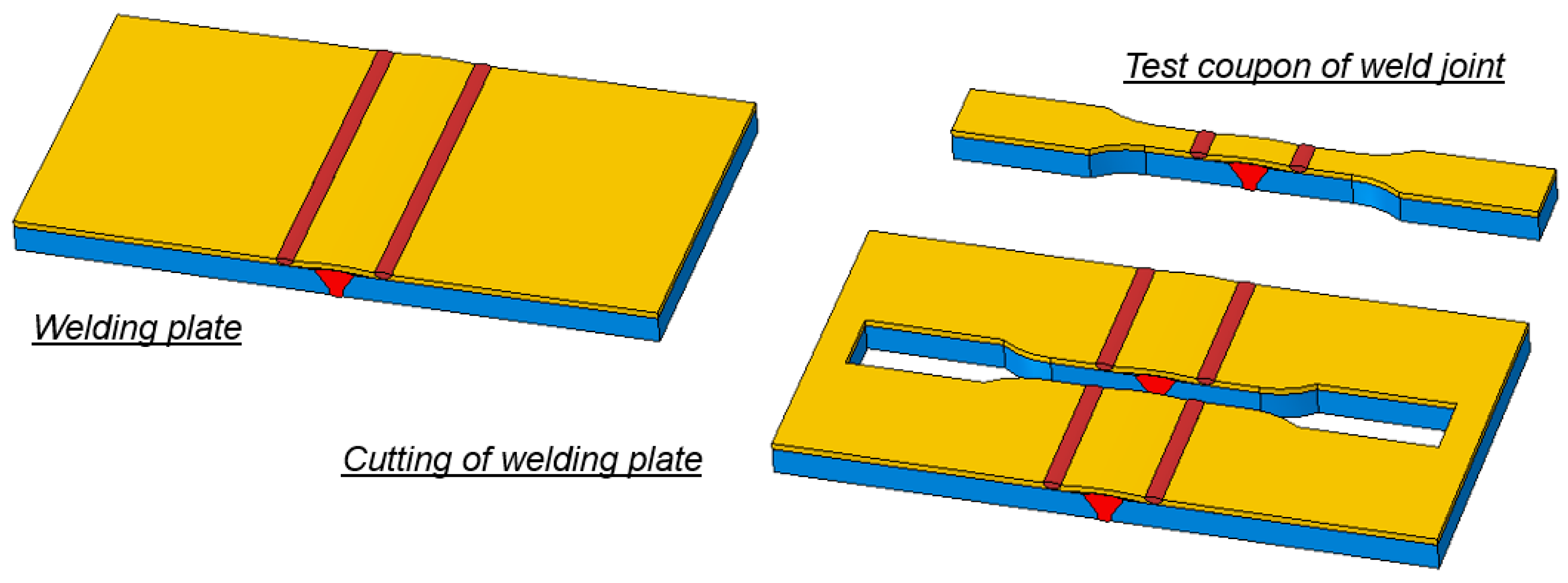
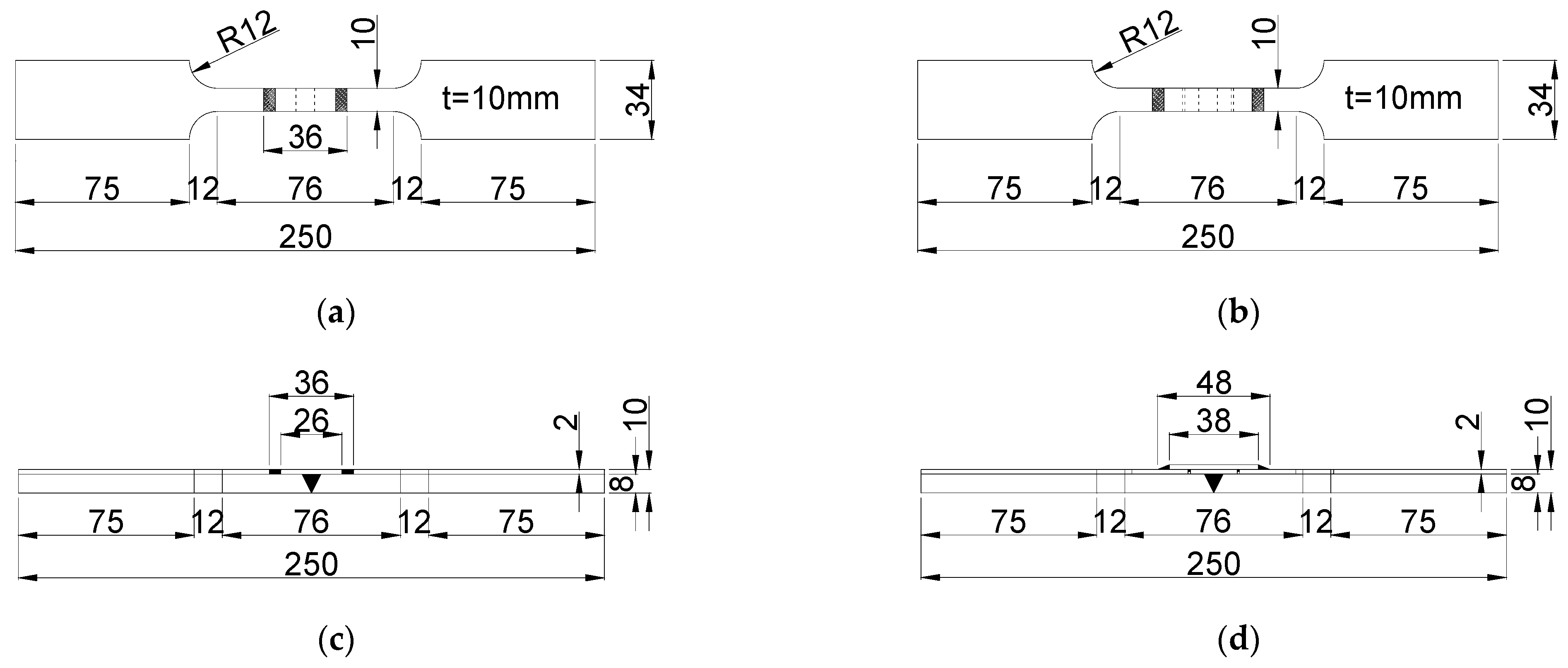
2.2. Geometric Dimensions of Test Coupons

The five types of TC bimetallic steel welded joints provided by Code GB/T 13149-2009 [21] (Figure 1) are not all suitable for application in building engineering. Clearly, type IV welded joint is unfavorable to be applied in the TC bimetallic steel members because of the arc-shaped nature of cover plate. Type V welded joint is also inconvenient for engineering application due to the cumbersome arrangement of cover plate. Type I welded joint can solely be utilized in conventional pressure vessels, rather than building engineering. Hence, the type II and type III welded joints are selected and investigated herein. For each type of welded joints selected, two TC bimetallic steel plates were grooved and butt welded along the full-length edges as described in Figure 2d. The representative welding process and welding plates are shown in Figure 4.
The geometrical dimensions of test coupons and test setup details are designed based upon the code of “Metallic materials—Tensile testing—Part 1: Method of test at room temperature” (GB/T 228.1-2010) [27]. The welding parameters refers to those summarized in Table 6. As indicated by Figure 5, the test coupons were wire-electrode cut and extracted from the afore-mentioned welded plates. The nominal geometrical dimensions of welded joint test coupons are plotted in Figure 6, while the photos of these coupons manufactured are shown in Figure 7. It should be noted that the filler titanium plate embedded into the clad-gap is spot-welded to the clad layers. Thus, the filler plate parts located within the spacing of spot-weld points are not essentially connected to the clad layers. When test coupons are cut and extracted, the filler plate cut becomes an individual part and usually falls down. As indicated by Figure 7d,e, the type III weld coupons may either possess or not possess a filler plate at the mid-length gap. On the other hand, type II welded joint may exhibit a slight separation between clad and substrate layers near the clad-to-cover-plate joints (Figure 7c). To capture the real geometric dimensions, the exact dimensions of five representative cross-sections are measured and summarized in Table 8. Among the five cross-sections, three are located in the projection of titanium cover plate, whilst two others are outside the cover-plate range. The gauge length for calculation of fracture elongation was also marked prior to the formal loading stage.

2.3. Loading Schemes and Measurement Arrangement

The tensile coupon tests were conducted at the key laboratory of civil engineering safety and durability of Tsinghua University. The loading equipment refers to a WE-100B electronic universal testing machine which possesses a bearing capacity of ±100 kN and a displacement range of ±200 mm. Within the linear elastic range, the test coupon is loaded by force-controlled method with a stress rate of 1 MPa/s. Once stress–strain nonlinearity is initiated, the force-controlled method is switched to a displacement-controlled one with a loading rate of 2.4 mm/min. The equivalent strain rate is 0.0005/s, satisfying the required loading rate range specified by GB/T 228.1-2010 [27]. The gauge length of extensometer is 50 mm and sufficient for measurement of the maximum length of welded joints. The loading device utilized herein is schematically depicted in Figure 8.
A family of BX120-3AA strain gauges are attached on the mid-length top surface of clad layer, bottom surface of substrate layer, the two side surfaces of substrate layer. The elastic modulus is calculated through the strain gauge records. However, when test material reaches strain-hardening range, the strain gauges usually fall off. The subsequent deformation is captured by the extensometer.

3. Results and Discussion

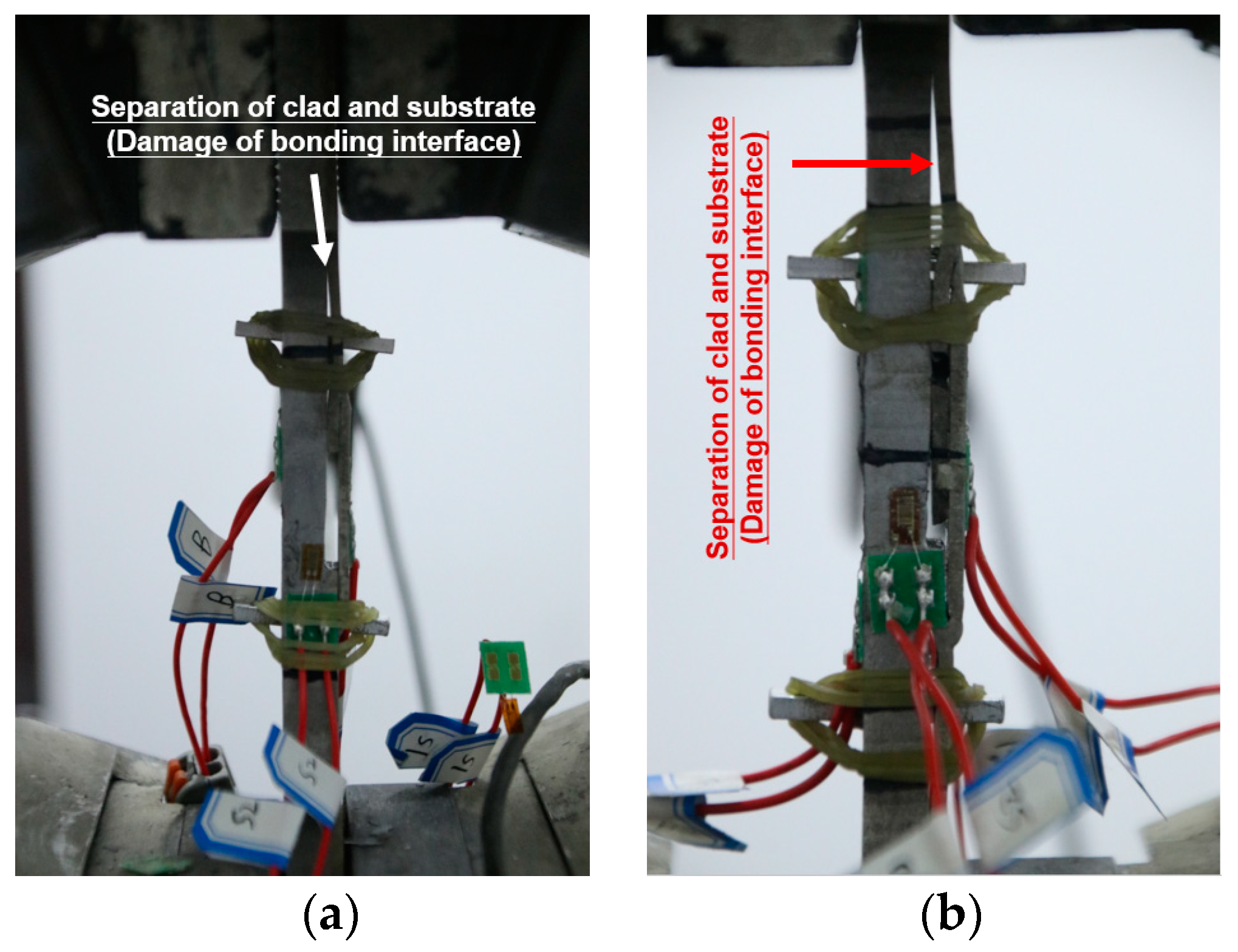
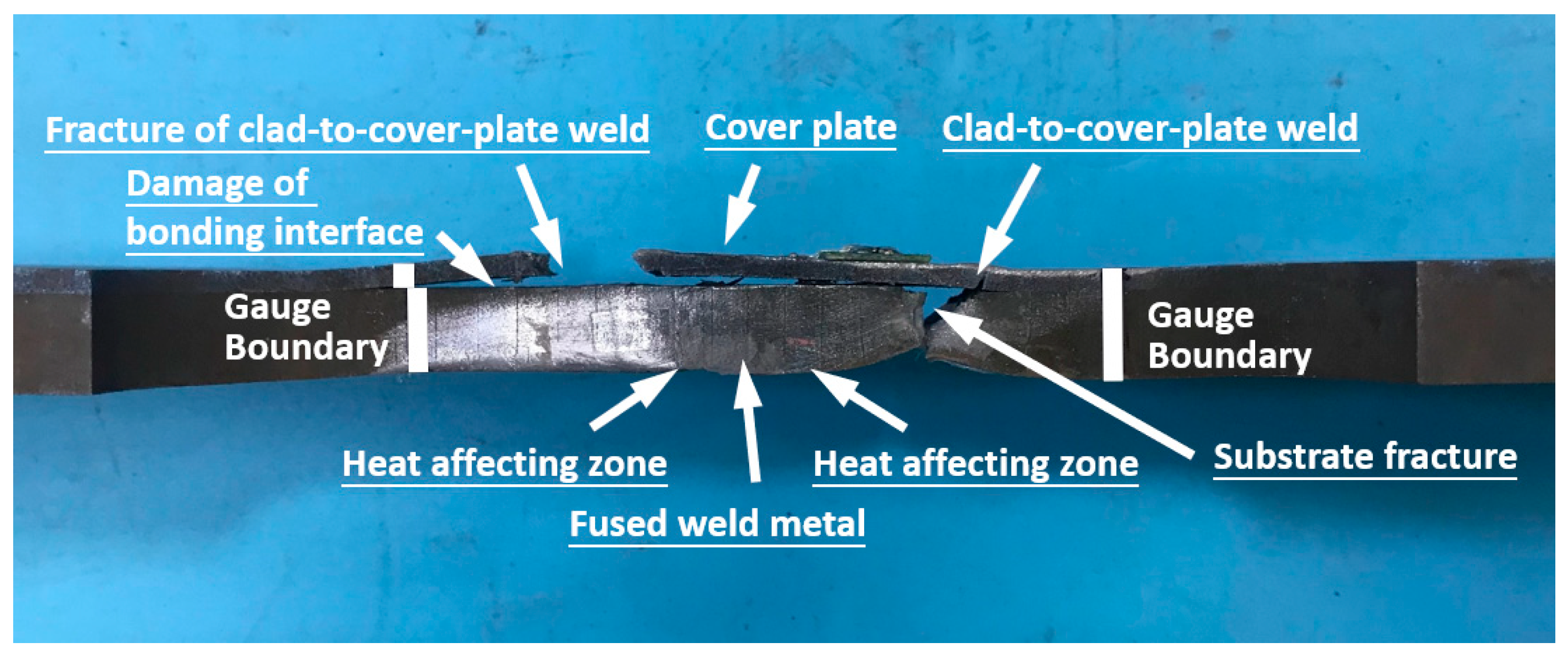
3.1. Experimental Phenomenon and Failure Modes

When formal loading stage is initiated for the type II welded joint, the clad layer and substrate layer are loaded together and exhibit an elastic stress–strain behavior. As stress increases, one weld between titanium cover plate and clad layer is firstly fractured (Figure 9a,b). The clad-to-substrate bonding interface near the first fracture position is slightly damaged to some extent. The external loading is then resisted solely by the substrate metal. The subsequent behavior is similar with that of the pure structural steel. After the appearance of ultimate tensile strength, the substrate metal is necked and finally fractured at the plane position of the undamaged clad-to-cover-plate weld.
As for the type III welded joint, the bonding interface is firstly damaged near the titanium fillet weld between the clad layer and the titanium cover plate (Figure 10). The clad layer and substrate layer is separated by an interface normal force transferred from the tension force of titanium cover plate. The first fracture is also observed at one weld between cover plate and clad layer (Figure 9c,d). Thereafter, the substrate metal provides the resistance solely. The necking and final fracture takes place near the edge of clad-elimination gap. The representative failure modes of type II and type III TC bimetallic steel butt-welded joints are respectively shown in Figure 11 and Figure 12.
It can be found that the substrate fracture positions of both types of welded joints are near the titanium-to-titanium weld spots. Nevertheless, no cracks and failure are observed near the mid-length substrate weld metal and HAZ. This reveals the truth that the titanium-to-titanium welding indeed deteriorates the substrate resistance by either physical way or chemical way. As for type II welded joints, the tiny grooves under the clad-to-cover-plate welds tend to act as the initial imperfection spot which leads to a considerable stress concentration. With regards to type III welded joints, the chemical element of melt titanium near the clad-to-cover-plate welds may more or less penetrate into the substrate layer, resulting in a weaken point of substrate at the material lever.

3.2. Stress-Strain Relations and Key Mechanical Properties

The stress–strain curves of all test coupons are shown in Figure 13. Clearly, the stress–strain curves of both types of welded joints exhibit distinct drop in stress when clad-to-cover-plate weld is firstly fractured. Subsequently, the substrate material can provide a promising strain-hardening ability prior to the ultimate strength point. The stress drop magnitude of type II welded joint is less than that of type III, whilst the strain-hardening magnitude of type II welded joint is greater than that of type III. Hence, the deformability of clad-to-cover-plate weld of type III joint is greater than that of type II joint. The first fracture of type III joint is closer to the ultimate strength point. Moreover, the first fracture stress of type II joint is less than the ultimate strength, whilst the first fracture stress of type III joint is considerably greater than the ultimate strength. The sharp drop of stress may introduce a more instable bearing capacity of type III joint. All stress–strain relations exhibit distinct full-range nonlinearity without yield plateau.
The crucial mechanical properties, including the elastic modulus E, 0.2% proof strength σ0.2, the first fracture stress σc,u, the initial stress after first fracture σs,0, the tensile strength of substrate σs,u, and the fracture elongation ψ, are summarized in Table 9. Note that the σ0.2 is obtained through the framework of iteration method specified by reference [28]. Within each iteration step, a transient elastic modulus is calculated by using the stress–strain relation corresponding to the stress amplitude of 0.1σ0.2~0.5σ0.2. The elastic modulus and 0.2% proof stress are repeatedly updated until the error between the elastic modulus calculated in two adjacent iteration steps is less than the error limit of 10 MPa. The mechanical properties of welded joints are compared with that of the corresponding parent material in Table 10. Moreover, the experimental results of tensile strength are compared with that of several other relevant studies [6,29,30]. The details are shown in Table 11.
According to the comparison shown in Table 10, except for the elastic modulus and 0.2% proof stress, the welded joint values of other indexes are all less than that of the corresponding parent material. The weld-to-parent ratio of ultimate strength for type II joint and type III joint are, respectively, 0.90 and 0.93. The fracture elongations of type II and type III welded joints are, respectively, 37% and 57% that of the parent material. The weld-parent difference of elastic modulus for type III are considerably greater than that of type II. The ratio between weld and parent elastic modulus of type II joint is 0.99, whilst that of type III joint is 0.70. This is because the geometrical feature of type II joint is relatively closed to the parent material. Nevertheless, the type III joint includes a weakened sector within which the clad metal is removed. Even though a titanium protection-cap is added thereafter, the geometrical imperfection of this cap tends to transfer a normal stress at the bonding interface and hence induces a separation of substrate and clad at the very initial loading state. Thus, the enhancement of this titanium protection-cap on the stiffness of weld joint is limited. Such special geometrical feature determines that the elastic modulus measured is much less than that of parent material. Overall, the two butt-welded joints studied herein possess promising load-bearing capacity but unfavorable ductility and deformability.
The bimetallic steels studied in Table 11 include a 316L+Q235B SC bimetallic steel [6], a TA1 + Q345 TC bimetallic steel [29], and a TA1 + Q235B TC bimetallic steel [30]. The clad ratios of them are, respectively, 0.38, 0.33, and 0.17. Evidently, their ratios of weld strength and parent metal strength are considerably different. The tensile strength of SC bimetallic steel is larger than the weld joint’s tensile strength. However, the weld joint of TA1 + Q345 TC bimetallic steel, whose clad ratio is 0.33, possesses a tensile strength solely 0.23 the parent material’s strength. Overall, all weld joints of TC bimetallic steels exhibit a weld/parent strength ratio smaller than 1.0. Based upon the current investigation, the weld SC bimetallic steel structure seems to be more applicable than the weld TC bimetallic steel structure. However, the strength and deformability of TC bimetallic steel weld joint can be influenced by a large number of factors, including the clad ratio, clad material, substrate material, geometrical feature, electrode combination, and welding procedure. The existing experimental records on TC bimetallic steel weld joints are extremely limited. In the future, the clarification on the influencing mechanism of weld joint performance demands a huge accumulation of experimental studies.

4. Design Recommendation

It is acknowledged that the titanium cover plate of different welded joints plays a key role in the corrosion resistance of welded TC bimetallic steel structure. Once the clad-to-cover-plate weld is fractured, the anti-corrosion protection is essentially removed, resulting in a complete exposure of substrate weld to corrosive environment. To avoid this danger, the design strength of the TC bimetallic steel butt-welded joints should be classified as two limit states. The first refers to a limit state where anti-corrosion coating begins to fail. The corresponding strength should be less than the stress corresponding to the clad-to-cover-plate fracture point. Once the stress exceeds such strength, the TC bimetallic steel structure loses its corrosion resistance. However, the structure still possesses sufficient ability to carry external loads and guarantee the short-term structural safety. The second limit state refers to a conventional critical point of structural safety. The strength should be taken as the ultimate strength of substrate weld joints. When such strength is reached, the structure is treated as completely failure. Clearly, if the strength of the first limit state is far less than the second one, the anti-corrosion advantages of TC bimetallic steel no longer exist and hence lose their long-term economic benefit. A rational structural design should restrict the strength gap between the first and second limit states by adjusting the type of parent material, the configuration of welded joint, and the selection of electrodes. On the other hand, even though little difference between the first and second limit state strengths can maximize the long-term anti-corrosion economy, the first limit state strength should not be greater than that of the second limit state based on perspective of failure warning. Specifically, the failure of clad-to-cover-plate weld is outside of the steel member and hence can act as a visible warning. Contrarily, if the substrate weld fracture is prior to the clad weld fracture, a severe collapse of overall structure may suddenly happen, leading to considerable barriers for evacuation. Thus, the structural design of welded TC bimetallic steel structure should also guarantee the strength of first limit state being less than the second one.
The welded joints of the TC bimetallic steel plate exhibit more complex configuration than that of other metals. Even though stainless-clad (SC) bimetallic steel also belongs to a cladding bimetallic metal, its configuration details are much simpler than that of TC bimetallic steel. This is because fusion welding of clad and substrate of SC bimetallic steel will not severely deteriorate the load-bearing capacity. Because of the complex configuration for the TC bimetallic steel butt-welded joint, different kinds of initial defects are likely to be generated. These defects tend to more or less deteriorate the load-bearing capacity and fatigue resistance of the welded joints. There exists two ways to solve this problem. The first is to develop a fusion welding approach applicable for titanium and structural steels. However, this approach demands a breakthrough in metallurgical and chemical subjects. The second way is to develop new simpler configuration for such welded joints. For instance, the titanium-cover-plate can be replaced by a sprayed anti-corrosion coating to avoid the existence of “titanium-to-titanium” and “steel-to-steel” weld structure. The upgraded welded joint structure should minimize the appearance of geometrical discontinuity and microdefect.

5. Conclusions

In this paper, the tensile behavior of two types of TC bimetallic steel butt-welded joints is studied through eight tensile coupon tests. The failure mechanism, stress–strain curves, and crucial mechanical properties are investigated and compared with that of parent material. The future structural design methodology of welded TC bimetallic steel structure is discussed. This study has filled in the study blanks of weld joints on TC bimetallic steel. The following conclusions can be drawn:
(1)
The fracture sequences of type II and type III are similar. The welded joint between clad layer and titanium cover plate tends to firstly fracture at the initial stage of strain-hardening range. The final fracture happens at the cross-section near the clad elimination edge. The stress–strain relations exhibit a distinct stress drop where the weld between clad layer and titanium cover plate is fractured. Subsequently, a strain-hardening behavior can be developed.
(2)
The fracture elongations of type II and type III welded joints are, respectively, 37% and 57% that of the parent material. However, the relative proportions of ultimate strength are, respectively, 90% and 93%. Overall, the two welded joints studied possess promising load-bearing capacity but unfavorable ductility and deformability.
(3)
The future investigation regarding welded TC bimetallic steel structure should clarify the structural design methods for the critical state of corrosion protection and the critical state of structural failure. Moreover, it is needed to develop fusion welding approaches of titanium and structural steel and reduce the geometrical complexity of existing TC bimetallic steel welded joints.

Author Contributions

Data curation, C.H.; Academic concepts, J.J.; Resources, H.B.; Supervision, H.B.; Literature search, L.H.; Writing—original draft, L.H.; Writing—review & editing, H.B. All authors have read and agreed to the published version of the manuscript.

Funding

This research was funded by the National Natural Science Foundation of China, grant number 52108155 and 52078272.

Institutional Review Board Statement

Not applicable.

Informed Consent Statement

Not applicable.

Data Availability Statement

No new data were created.

Conflicts of Interest

The authors declare no conflict of interest.

References

  1. Soufeiani, L.; Foliente, G.; Nguyen, K.; Nicolas, R. Corrosion protection of steel elements in façade systems—A review. J. Build. Eng. 2020, 32, 101759. [Google Scholar] [CrossRef]
  2. Ban, H.; Shi, Y. An innovative high performance steel product for structural engineering: Bi-metallic steel. In Proceedings of the International Conference on Engineering Research and Practice for Steel Construction, Hong Kong, China, 5–7 September 2018; Volume 9, pp. 424–430. [Google Scholar]
  3. Ban, H.; Shi, Y.; Tao, X. Use of clad steel in engineering structures. In Proceedings of the Fifteenth East Asia-Pacific Conference on Structural Engineering & Construction (EASEC-15), Xi’an, China, 11–13 October 2017; pp. 1167–1173. [Google Scholar]
  4. Ban, H.; Bai, R.; Yang, L.; Bai, Y. Mechanical properties of stainless-clad bimetallic steel at elevated temperatures. J. Constr. Steel Res 2019, 162, 105704. [Google Scholar] [CrossRef]
  5. Liu, X.; Ban, H.; Zhu, J.; Uy, B. Cyclic behaviour and modelling of stainless-clad bimetallic steels with various clad ratios. Steel Compos. Struct. 2020, 34, 189–213. [Google Scholar]
  6. Ban, H.; Zhu, J.; Shi, G. Cyclic loading tests on welded connections of stainless-clad bimetallic steel and modelling. J. Constr. Steel Res. 2020, 171, 106140. [Google Scholar] [CrossRef]
  7. Mei, Y.; Ban, H. High strain rate behaviour of stainless-clad bimetallic steel. Eng. Struct. 2020, 207, 110219. [Google Scholar] [CrossRef]
  8. Ban, H.; Bai, R.; Chung, K.; Bai, Y. Post-fire material properties of stainless-clad bimetallic steel. Fire Saf. J. 2020, 112, 102964. [Google Scholar] [CrossRef]
  9. Ban, H.; Zhu, J.; Shi, G.; Zhang, Y. Tests and modelling on cyclic behaviour of stainless-clad bimetallic steel. J. Constr. Steel Res. 2020, 166, 105944. [Google Scholar] [CrossRef]
  10. Hai, L.; Ban, H. Full-range stress-strain relation of stainless-clad bimetallic steel: Constitutive modelling. J. Build. Eng. 2022, 57, 104868. [Google Scholar] [CrossRef]
  11. Su, H.; Luo, X.; Chai, F.; Shen, J.; Sun, X.; Lu, F. Manufacturing Technology and Application Trends of Titanium Clad Steel Plates. J. Iron. Steel Res. Int. 2015, 22, 977–982. [Google Scholar] [CrossRef]
  12. Yang, D.; Luo, Z.; Xie, G.; Jiang, T.; Zhao, S.; Misra, R.D.K. Interfacial microstructure and properties of a vacuum roll-cladding titanium-steel clad plate with a nickel interlayer. Mater. Sci. Eng. A 2019, 753, 49–58. [Google Scholar] [CrossRef]
  13. Bi, Z.-X.; Li, X.-J.; Yang, K.; Kai, R.; Wang, Q.; Xu, M.-B.; Zhang, T.-Z.; Dai, X.-D.; Qian, J.-Y.; Wu, Y. Experimental and numerical studies of titanium foil/steel explosively welded clad plate. Def. Technol. 2022. [Google Scholar] [CrossRef]
  14. Liu, X.; Bai, R.; Uy, B.; Ban, H. Material properties and stress-strain curves for titanium-clad bimetallic steels. J. Constr. Steel Res. 2019, 162, 105756. [Google Scholar] [CrossRef]
  15. Rohatgi, H.; Yuvaraj, N. Analyse the effect of clad ratio on the stress-strain curve of titanium-clad bimetallic steel for different strain rates and temperatures using Johnson-Cook model. Mater. Today Proc. 2022, 56, 3702–3713. [Google Scholar] [CrossRef]
  16. Huang, C.; Ban, H.; Hai, L.; Jiang, J.; Shi, Y. Research on high-cycle fatigue properties of hot rolled titanium-clad bimetallic steel with low bonding strength. J. Build. Struct. 2022, 43, 36–43. [Google Scholar]
  17. Huang, C.; Ban, H.; Hai, L.; Shi, Y. Fatigue behaviour of titanium-clad bimetallic steel plate with different interfacial conditions. In Proceedings of the Tenth International Conference on Advances in Steel Structures (ICASS’ 2020), Chengdu, China, 21–23 August 2022. [Google Scholar]
  18. Huang, C.; Hai, L.; Jiang, J.; Ban, H. High-cycle fatigue properties of explosion bonded titanium-clad bimetallic steel. Int. J. Fatigue 2023, 169, 107499. [Google Scholar] [CrossRef]
  19. Shi, Y.; Luo, Z.; Zhou, X.; Xue, X.; Li, J. Post-fire mechanical properties of titanium–clad bimetallic steel in different cooling approaches. J. Constr. Steel Res. 2022, 191, 107169. [Google Scholar] [CrossRef]
  20. Hai, L.; Ban, H.; Huang, C.; Shi, Y. Experimental cyclic behaviour and constitutive modelling of hot-rolled titanium-clad bimetallic steel. Constr. Build. Mater. 2022, 360, 129591. [Google Scholar] [CrossRef]
  21. GB/T 13149-2009; General Administration of Quality Supervision, Inspection and Quarantine of the People’s Republic of China. Specification for Welding of Titanium and Titanium Alloy Clad Steel Plates. Standards Press of China: Beijing, China, 2009.
  22. GB/T 3621-2007; General Administration of Quality Supervision, Inspection and Quarantine of the People’s Republic of China. Titanium and Titanium Alloy Plate and Sheet. Standards Press of China: Beijing, China, 2007.
  23. GB/T 1591-2018; State Administration of Market Supervision. High Strength Low Alloy Structural Steels. Standards Press of China: Beijing, China, 2018.
  24. GB/T 8547-2019; State Administration of Market Supervision. Titanium Clad Steel Plate. Standards Press of China: Beijing, China, 2019.
  25. GB/T 8110-2008; General Administration of Quality Supervision, Inspection and Quarantine of the People’s Republic of China. Welding Electrodes and Rods for Gas Shielding Arc Welding of Carbon and Low Alloy Steel. Standards Press of China: Beijing, China, 2009.
  26. NB/T 47018.7-2017; Technical Permission of Welding Materials for Pressure Equipment Section 7: Titanium and Titanium-Alloy Welding Electrodes and Rods. National Energy Administration: Beijing, China, 2017.
  27. GB/T 228.1-2010; General Administration of Quality Supervision, Inspection and Quarantine of the People’s Republic of China. Metallic Materials—Tensile Testing—Part 1: Method of Test at Room Temperature. Standards Press of China: Beijing, China, 2011.
  28. Ban, H.; Zhou, G.; Yu, H.; Shi, Y.; Liu, K. Mechanical properties and modelling of superior high-performance steel at elevated temperatures. J. Constr. Steel Res. 2021, 176, 106407. [Google Scholar] [CrossRef]
  29. Liu, D.; Wang, W.; Zha, X.; Jiao, H.; Zhao, L.; Han, S. Experimental investigation of butt welded Ti/steel bimetallic sheets by using multi-principal powders as a single filler metal. J. Mater. Res. Technol. 2021, 15, 1499–1512. [Google Scholar] [CrossRef]
  30. Zhang, H.; Zhang, L.; Liu, J.; Ning, J.; Zhang, J.; Na, S.; Zhu, L. Microstructures and performances of the butt joint of TA1/Q235B bimetallic sheet with addition of a Mo interlayer by using narrow gap laser welding with filler wire. J. Mater. Res. Technol. 2020, 9, 10498–10510. [Google Scholar] [CrossRef]
Figure 1. Five types of TC bimetallic steel welded joints provided by GB/T 13149.
Buildings 13 00912 g001
Figure 2. Different cross-sectional types of box-shaped TC bimetallic steel members. (a) Conventional four-corner-weld cross-section for steel member, (b) Updated four-corner-weld cross-section for TC bimetallic steel member, (c) Cold-formed cross-section for TC bimetallic steel member, (d) Doubly-U-shaped cross-section for TC bimetallic steel member.
Buildings 13 00912 g002
Figure 3. The groove nature of TC bimetallic steel weld joints utilized in ocean building engineering.
Buildings 13 00912 g003
Figure 4. Manufacture of TC bimetallic steel welding plates. (a) Welding process, (b) TC bimetallic steel welding plates.
Buildings 13 00912 g004
Figure 5. Manufacture of test coupons from TC bimetallic steel welding plates.
Buildings 13 00912 g005
Figure 6. Geometric dimensions of test coupons for TC bimetallic steel welded joints. (a) Type II: plan size, (b) Type III: plan size, (c) Type II: side view and (d) Type III: side view.
Buildings 13 00912 g006
Figure 7. Photos of test coupons of TC bimetallic steel welded joints. (a) Test coupons of welded joints, (b) Type II welded joints, (c) Type II welded joints with initial bonding interface damage, (d) Type III welded joints with filler plate and (e) Type III welded joints without filler plate.
Buildings 13 00912 g007
Figure 8. Real graphic of loading machine.
Buildings 13 00912 g008
Figure 9. Fracture of clad-to-cover-plate welded joints. (a) Weld II, (b) Weld II, (c) Weld III, and (d) Weld III.
Buildings 13 00912 g009
Figure 10. Local separation of clad and substrate layers. (a) Type III welded joint without filler plate and (b) Type III welded joint with filler plate.
Buildings 13 00912 g010
Figure 11. Failure mode of type II TC bimetallic steel butt-welded joints.
Buildings 13 00912 g011
Figure 12. Failure mode of type III TC bimetallic steel butt-welded joints.
Buildings 13 00912 g012
Figure 13. Experimental stress-strain curves of test coupons. (a) Test curves of type II welded joint, (b) Test curves of type III welded joint, (c) Relationship between failure mechanism and stress–strain relations (type II welded joint) and (d) Relationship between failure mechanism and stress–strain relations (type III welded joint).
Buildings 13 00912 g013
Table 1. Chemical composition of substrate of TC bimetallic steel tested (mass fraction, %).
CSiMnPSAlsNiCrCuNbVTiMoCeq
0.160.321.510.0140.0040.0260.010.020.010.0010.0040.0020.0030.42
Table 2. Mechanical properties provided by certificate warranty.
β *Y.S. (MPa)T.S. (MPa)EL (%)Bend α = 180° d = 2aCharpy (J, °C)τ0 (MPa)
0.2415.0530.028.96Qualified164185.6
* β describes the clad ratio, E0 represents the elastic modulus, Y.S. denotes the yield strength, T.S. represents the ultimate strength (tensile strength), EL denotes the fracture elongation, τ0 denotes the shear strength of bonding interface between clad and substrate layers.
Table 3. Measured mechanical properties of clad, substrate, and TC bimetallic steel [20].
MaterialβE0 (GPa)σ0.2 * (MPa)σsh (MPa)σu (MPa)[σ0.2] (MPa)[σu] (MPa)EL (%)τ0 (MPa)[τ0] (MPa)
TA2 + Q355B0.2185.0395.1419.0566.1≥331≥45631.4%200.6≥140
Clad (TA2)1.0104.2314.7363.5397.6275~450≥40041.1%N/AN/A
Substrate (Q355B)0.0201.8435.7443.1619.5≥355470~63029.3%N/AN/A
* σ0.2 denotes the 0.2% proof stress; σsh describes the stress value corresponding to the termination strain of yield plateau of structural steel. σu represents the ultimate strength (tensile strength), [σ0.2] and [σu], respectively, represents the codified limitation of 0.2% proof stress and ultimate strength according to GB/T 3621-2007 and GB/T1591-2018. [τ0] refers to the codified limitation of shear strength on bonding interface. The square bracket refers to the boundary value of the corresponding mechanical index. The other symbols including β, E0, EL, and τ0 are identical with those listed in Table 2.
Table 4. Chemical composition of substrate electrode ER55-Ni1 (%).
CSiMnPSNiCrCuVMoEtcCSi
0.120.4~0.81.250.0250.0250.8~1.10.150.350.050.350.50.120.4~0.8
Table 5. Chemical composition of clad electrode ERTA2ELI (%).
Primary
Element
Impurity ElementResidual Element
TiFeOCNHSingleSum
Residual≤0.120.08~0.16≤0.03≤0.015≤0.008≤0.05≤0.20
Table 6. Welding controlling parameters.
Metal TypeWelding TypeElectrodeCurrent (A)Voltage (V)Speed (mm/min)
SteelGTAW manualER55-Ni1 Φ1.2130–18010–1240–45
SteelGTAW machineER55-Ni1 Φ1.2270–28012–1480–100
TitaniumGTAW manualERTA2ELI Φ1.690–10010–12Spot
TitaniumGTAW manualERTA2ELI Φ1.690–10010–12100–110
Table 7. Mechanical property demands of substrate electrode.
ElectrodeShielding GasTensile StrengthYield StrengthElongationStatus
ER50-XCO2≥500 MPa≥420 MPa≥22%As welded
ER55-NiXAr + (1%~5%) O2≥550 MPa≥470 MPa≥24%As welded
Table 8. Measured geometric dimensions of different coupons.
Test CouponParameterPosition of Cross-Section
L *MLMMRR
WII-1Width (mm)9.929.899.879.849.92
WII-29.929.909.919.829.88
WII-39.939.879.889.879.94
WII-49.869.899.879.909.91
WIII-19.819.869.889.879.91
WIII-29.799.789.779.849.81
WIII-39.869.859.889.849.88
WIII-49.919.889.849.799.83
WII-1Thickness (mm)10.7010.7210.5710.6710.61
WII-210.2110.8810.6210.9510.44
WII-310.6411.5310.9310.9010.44
WII-410.2710.9510.6910.7210.40
WIII-110.3412.4512.7012.7910.33
WIII-210.3312.4312.2012.6710.30
WIII-310.4712.8812.6912.8610.40
WIII-410.3912.4412.2512.4410.39
WII-1Area (mm2)106.14106.02104.33104.99105.25
WII-2101.28107.71105.24107.53103.15
WII-3105.66113.80107.99107.58103.77
WII-4101.26108.30105.51106.13103.06
WIII-1101.44122.76125.48126.24102.37
WIII-2101.13121.57119.19124.67101.04
WIII-3103.23126.87125.38126.54102.75
WIII-4102.96122.91120.54121.79102.13
* L: The left cross-section outside the projection of cover plate; R: The right cross-section outside the projection of cover plate; ML: The left edge cross-section within the projection of cover plate; MR: The right edge cross-section within the projection of cover plate; M: The middle cross-section within the projection of cover plate.
Table 9. Crucial tensile mechanical properties of type II and type III TC bimetallic steel welded joints.
CouponE
(GPa)
ε0.2σ0.2
(MPa)
εc,uσc,u
(Mpa)
εs,0σs,0
(Mpa)
εs,uσs,u
(Mpa)
ψ
WII-1191.70.40%370.70.87%402.71.16%373.08.96%506.513.30%
WII-2215.40.39%407.71.18%434.01.66%408.59.03%514.613.34%
WII-3145.00.49%415.20.51%416.10.63%373.25.07%506.410.54%
WII-4181.40.42%400.40.48%403.90.73%373.97.64%515.39.40%
Mean183.40.43%398.50.76%414.21.04%382.17.68%510.711.65%
WIII-1127.80.49%370.47.06%595.88.30%533.28.81%533.919.90%
WIII-2110.20.55%382.44.70%565.45.86%510.411.10%536.613.57%
WIII-3142.80.46%380.83.99%548.34.53%487.812.96%520.018.76%
WIII-4138.80.43%315.62.43%490.72.98%453.19.66%520.918.87%
Mean129.90.48%362.34.54%550.15.42%496.110.63%527.917.78%
Table 10. Comparison of mechanical properties between parent material and weld joints.
PropertiesParent
Material
Type II Weld JointType III Weld Joint
Test ValueWeld/ParentTest ValueWeld/Parent
Elastic modulus E (GPa)185.0183.40.99129.90.70
Proof strength σ0.2 (Mpa)395.1398.51.01362.30.92
Tensile strength σu (Mpa)566.1510.70.90527.90.93
Fracture elongation ψ31.40%11.65%0.3717.78%0.57
Table 11. Comparison of tensile strength on different weld joints of bimetallic steels.
MaterialTensile Strength
TypeCladSubstrateClad RatioParent (Mpa)Weld (Mpa)Weld/Parent
SC [6]316L (3 mm)Q235B (5 mm)0.38618.0644.21.04
TC [29]TA1 (1 mm)Q345 (2 mm)0.33499.0117.00.23
TC [30]TA1 (1 mm)Q235B (5 mm)0.17502.2467.00.93
TC *TA2 (2 mm)Q355B (8 mm)0.20566.1510.70.90
TC *TA2 (2 mm)Q355B (8 mm)0.20566.1527.90.93
* Experimetnal data of this study.
Disclaimer/Publisher’s Note: The statements, opinions and data contained in all publications are solely those of the individual author(s) and contributor(s) and not of MDPI and/or the editor(s). MDPI and/or the editor(s) disclaim responsibility for any injury to people or property resulting from any ideas, methods, instructions or products referred to in the content.

