Article

Optimising Design Parameters of a Building-Integrated Photovoltaic Double-Skin Facade in Different Climate Zones in Australia

1
School of Built Environment, Engineering and Computing, Leeds Beckett University, Leeds LS2 8AG, UK
2
School of Built Environment, University of New South Wales, Sydney, NSW 2052, Australia
3
Department of Civil, Environmental, Land, Building Engineering and Chemistry, Polytechnic University of Bari, 70126 Bari, Italy
4
School of Photovoltaic and Renewable Energy Engineering, University of New South Wales, Sydney, NSW 2052, Australia
*
Author to whom correspondence should be addressed.
Buildings 2023, 13(4), 1096; https://doi.org/10.3390/buildings13041096
Submission received: 31 March 2023 / Revised: 13 April 2023 / Accepted: 19 April 2023 / Published: 21 April 2023
(This article belongs to the Special Issue Novel Technologies for Energy Efficiency in Buildings)

Abstract

:
Energy used in buildings is mainly attributed to provide the desired thermal comfort, which could result in an increase in carbon emission and, in turn, lead to further environmental degradation. A Building-Integrated Photovoltaic Double-Skin Façade (BIPV-DSF) is a promising way to maintain indoor thermal comfort, obtained with low environmental impact and energy consumption. The appropriate design of BIPV-DSFs can maximise indoor thermal comfort and energy efficiency for buildings. This paper presents optimal BIPV-DSF design solutions, which are dedicated to offering comfortable and energy-efficient buildings, through optimisation of the most important design parameters of a BIPV-DSF under three different climate conditions in Australia. The results illustrate how thermal transmittance (U-value) and solar heat gain coefficient (SHGC) of windows of the BIPV-DSF, as the most important design parameters, were optimised for application in the context of different climates, operation modes, and orientations. The paper contributes to the matters concerning the integrated effect of BIPV-DSFs on thermal comfort and energy performance in buildings.

Graphical Abstract

1. Introduction

The impact of built environment on climate change has become significant [1], which is responsible for 39% of global carbon emissions, far higher than other sectors [2]. Greenhouse gases are the main driver of climate change [3], while carbon dioxide accounts for about 76% of total greenhouse gas emissions [4]. According to the statistics revealed in the 2022 World Economic Forum Annual Meeting [5], buildings as a major component within the built environment contribute to a high 37% of carbon emissions due to energy consumption, while office buildings are one of the substantial sources of energy consumption [6]. As a matter of fact, a large proportion of the energy consumption goes to the maintaining of thermal comfort in buildings [7]. Thus, the control of energy consumption and thermal comfort in buildings is crucial in mitigating climate change [8].
As an important part of a building, façades link the interior and exterior environments, which affects energy consumption and indoor thermal comfort in the building to a large extent [9]. However, conventional facades can lead to an increase in energy consumption and thermal discomfort due to their poor insulation and ventilation performance [10]. In comparison, adaptive façades can adapt to variable climatic conditions and thereby reduce building energy consumption and improve indoor thermal comfort, and these performances have been demonstrated in the last few decades [11,12,13]. Building-Integrated Photovoltaic Double-Skin Façade (BIPV-DSF) is considered one of the enabling adaptive façade technologies [14] showing the capability of reducing energy consumption and delivering comfortable indoor thermal condition for buildings [15,16], and has received the attention of researchers over the last ten years. However, most of the studies focused separately on either energy or indoor thermal comfort performance of the BIPV-DSF, while limited research has studied the combined effects [17,18,19,20,21,22,23,24,25,26,27,28,29,30].
Recently, the authors of this paper reported a sensitivity analysis [31] in which both energy consumption and indoor thermal comfort of a BIPV-DSF-equipped office building were investigated by identifying the most important design parameters of the BIPV-DSF. However, the actual values of the most important design parameters were not defined in the sensitivity analysis, which was inadequate to quantify the overall performance of the BIPV-DSF. Basically, the most important design parameters of the BIPV-DSF were thermal transmittance (U-value) of the BIPV-DSF’s internal window and solar heat gain coefficient (SHGC) of the BIPV-DSF’s external window. Elsharkawy and Zahiri [32] reported that a U-value of 0.5 W/m2K or 0.3 W/m2K for external walls could effectively reduce heating energy demand as well as maintain indoor thermal comfort for a domestic building in London (UK), whereas the window U-value was not evaluated. In the climate condition of Roorkee (India), Kumar and Suman [33] found that the building cooling load could be reduced with a lower U-value of the building envelope excluding the windows. In terms of the external windows, Liu et al. [34] found that the window U-value of 0.3 W/m2K could reduce heat losses through the window itself in winter and help improve indoor thermal comfort in summer, where an external shutter was applied. Song et al. [35] point out that the indoor thermal comfort of buildings in both severe cold and cold zones in China could be significantly improved by appropriately decreasing both the U-value and SHGC of the external windows; in this case, the SHGC in particular was decreased to 0.3, which could achieve more than 86% discomfort hours reduction. Aside from the regular building envelope/facades context, there is a paucity of research on the optimisation of U-values and SHGCs for DSFs or BIPV-DSFs. By means of an experimental study in Hong Kong (China), Peng et al. [20] conclude that the respective U-values of a naturally ventilated and a non-ventilated BIPV-DSF were 3.8 W/m2K and 3.4 W/m2K, respectively, while the respective SHGCs for both the naturally and non-ventilated scenarios were 0.12 and 0.13. However, these were average values for the overall BIPV-DSF.
The research presented in this paper quantitatively investigated the effect of BIPV-DSF on the concurrent performance of energy consumption and thermal comfort in buildings by optimising the most important design parameters of the BIPV-DSF. In terms of optimisation method, Pareto optimality [36] has been used to determine the optimal values of the most important design parameters from a set of feasible solutions. Pareto optimality is widely used in the optimisation of multiple objectives for the performance of buildings and building energy systems. Maltais et al. [37] optimised the trade-offs between two objectives (that is, annual lighting energy demand and annual glaring index) in Montreal (Canada) using Pareto optimality. Bre et al. [38] introduced a multi-objective optimisation method based on Pareto optimality to obtain the best trade-off between heating and cooling performance for dwellings. Ameur et al. [39] presented a co-simulation modelling study using Pareto optimality for the optimisation of thermal and lighting energy performance in a naturally ventilated residential building, thereby defining the design parameters more specifically. Chi and Xu [40] optimised the building performance of a student accommodation in Hangzhou (China) through Pareto optimality in terms of building energy consumption and thermal and visual comforts, where the optimal solutions of the related design parameters, such as the dimension of the shading device, building orientation, and window-to-ratio, were determined. In terms of the optimisation for BIPVs, Wijeratne et al. [41] demonstrated the use of a multi-objective optimisation method of Pareto optimality for identifying the optimal design solutions of feasible BIPV envelopes over the course of decision-making processes in early design stages.
In this paper, the most important design parameters of the BIPV-DSF of an Australian office module, according to the sensitivity analysis we recently presented [31], were optimised by using a specific optimisation method, namely Pareto optimality. Consequently, the optimal design solutions of the BIPV-DSF affecting the indoor thermal comfort and thermal energy consumption of the office module were determined for various contexts.

2. Methods

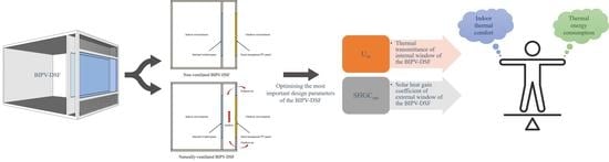
2.1. Design Parameters to Be Optimised

In general, this study was a continuation of our previous studies [26,27,28,29] and was especially based upon the most important design parameters of the BIPV-DSF identified through the previously conducted sensitivity analysis [31]. The parameters can be summarised in Table 1. The best-performing ventilation modes of the BIPV-DSF in the context of three distinctive climate conditions (represented by three Australian cities—Darwin, Sydney, and Canberra) can be summarised in Table 2 as per our previous studies [28,29]. Moreover, the BIPV-DSF facing four different orientations (due north, due south, due east, and due west) were considered in the optimisation.

2.2. Optimisation Methods

2.2.1. Design Parameters for Optimisation

The proposed optimisation was carried out by perturbing the important design parameters within a range of variations from their original values, and then determining the optimal design parameter values based upon the resultant variations of indoor thermal comfort and thermal energy consumption from the simulation modelling in TRNSYS. Furthermore, the perturbation of thermal parameters of the PV glazing (external window) could not be implemented due to the limitation of the manufacturer’s information. Thus, a regular window with a range of thermal parameters, such as SHGC, based on the International Glazing Database in the TRNSYS window library, was chosen to model the external window of the BIPV-DSF, while the PV electric power production was calculated separately. Table 3 presents the variation space (including the original values) for the identified most important design parameters for optimisation, where the values for perturbing the glazing-related parameters were taken from the International Glazing Database. It should be noted that the values of Uin and SHGCout were not varied regularly due to the confined capacity of the database at the time of the study.
Although there is a lack of evidence showing the impact of SHGC and U-value on the efficiency of PV glazing, a previous study [42] indicates that a PV glazing with a lower SHGC and U-value may be more efficient as less solar thermal heat will be transmitted than a PV glazing with a higher SHGC and U-value. On the other hand, Chen et al. [43] demonstrated higher PV efficiencies would result in a lower SHGC. It was assumed that there was no interference between PV efficiency and SHGC for the semi-transparent PV glazing in this study, as the efficiency of the selected semi-transparent PV panel was not as high as an opaque crystalline silicon PV panel. In fact, the reduced light absorbance determines semi-transparent PVs have much lower efficiency than opaque ones [44]. As a result, the PV efficiency under the standard test condition (STC) was fixed in this study, and varying U-value of the PV glazing (Uout) was not considered in the proposed optimisation.

2.2.2. Mathematical Model

Basically, the indoor thermal comfort was evaluated by counting discomfort hours using the “analytical comfort zone method” given by ASHRAE 55 [45]. Specifically, the discomfort hours were calculated for the Predicated Mean Vote (PMV) comfort zone, which can be implemented using the following equation in association with TRNSYS simulation [45]:
EH = ∑Hdisc
Hdisc = 1 if |PMV| − 0.5 > 0 and 0 otherwise
where EH is the exceedance hours or total discomfort hours, and Hdis is a discomfort hour.
To estimate thermal energy consumption of the proposed office module, the following equations based on the sensible heat gains (in terms of conduction, convection and radiation) were used in association with TRNSYS simulation [46]:
qs,i = qcomb,s,i + Ss,i + Wallgain
qs,o = qcomb,s,o + Ss,o
where qs,i is the conductive heat flux from the wall at the inside surface, qs,o is the conductive heat flux into the wall at the outside surface, qcomb,s,i is the combined convective and radiative heat flux in the space, qcomb,s,o is the combined convective and radiative heat flux to the surface, Ss,i is both the solar radiation and long-wave radiation generated from internal objects, Ss,o is the solar radiation from external surfaces, and Wallgain is a user-defined energy flow to the inside wall or window surfaces.
In addition, PV electric power production would influence thermal energy saving for the office module and, therefore, the net thermal energy consumption. The following equations were used in TRNSYS simulation for the calculation of PV-produced electricity [47], which was also considered in the net thermal energy consumption simulation:
PPV = A · (τα)n · IAM · GT · ηPV
IAM = ( τ α ) ( τ α ) n
where PPV is the PV electric power production, A is the PV panel exposed area, τα is the product of the PV panel’s transmittance and absorptance, the subscript n is the normal incidence angle of the solar radiation, IAM is the incidence angle modifier, GT is the total incident solar radiation on the PV panel surface, and ηPV is the PV power conversion efficiency.

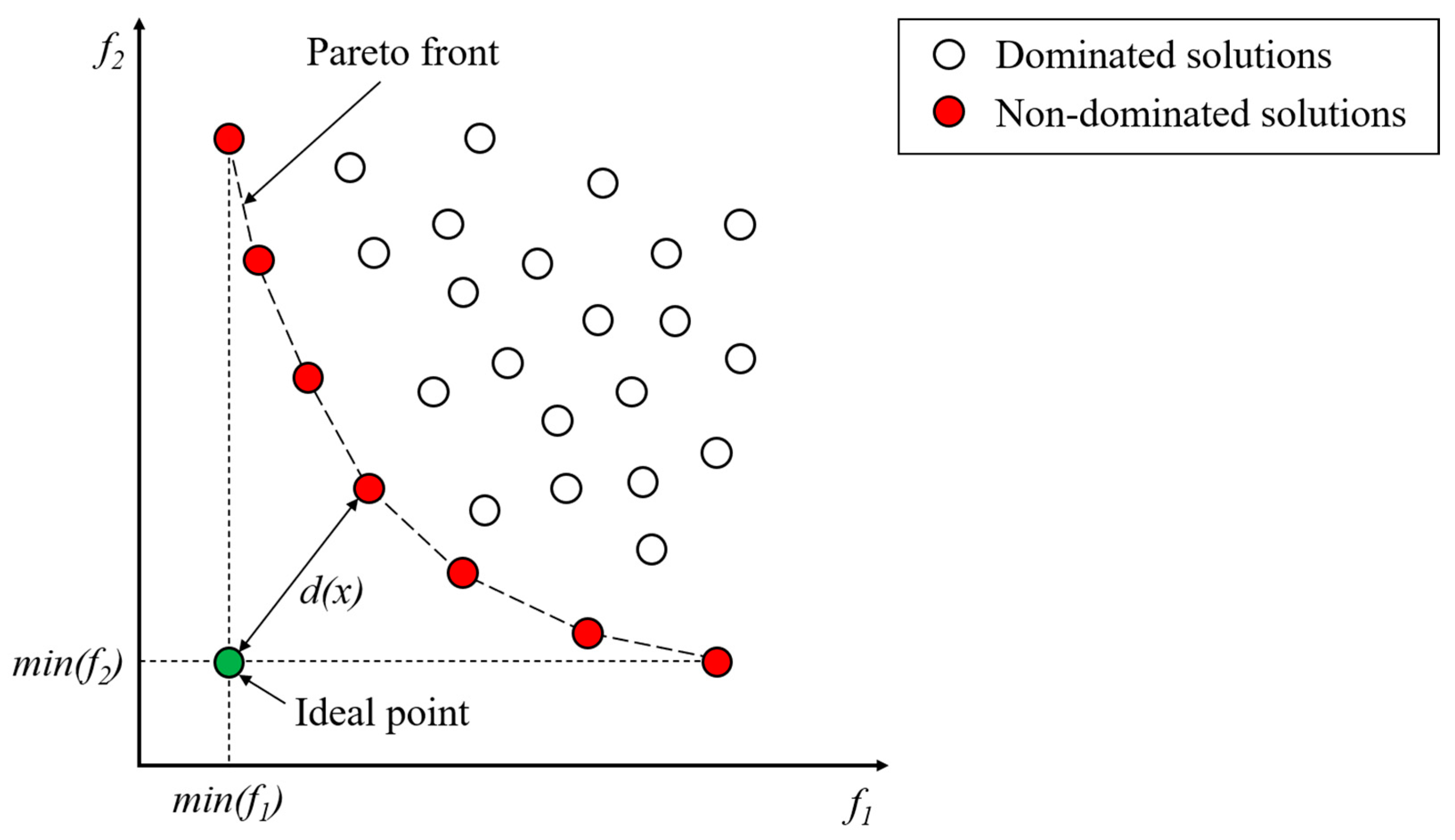
2.2.3. Pareto Optimality Method
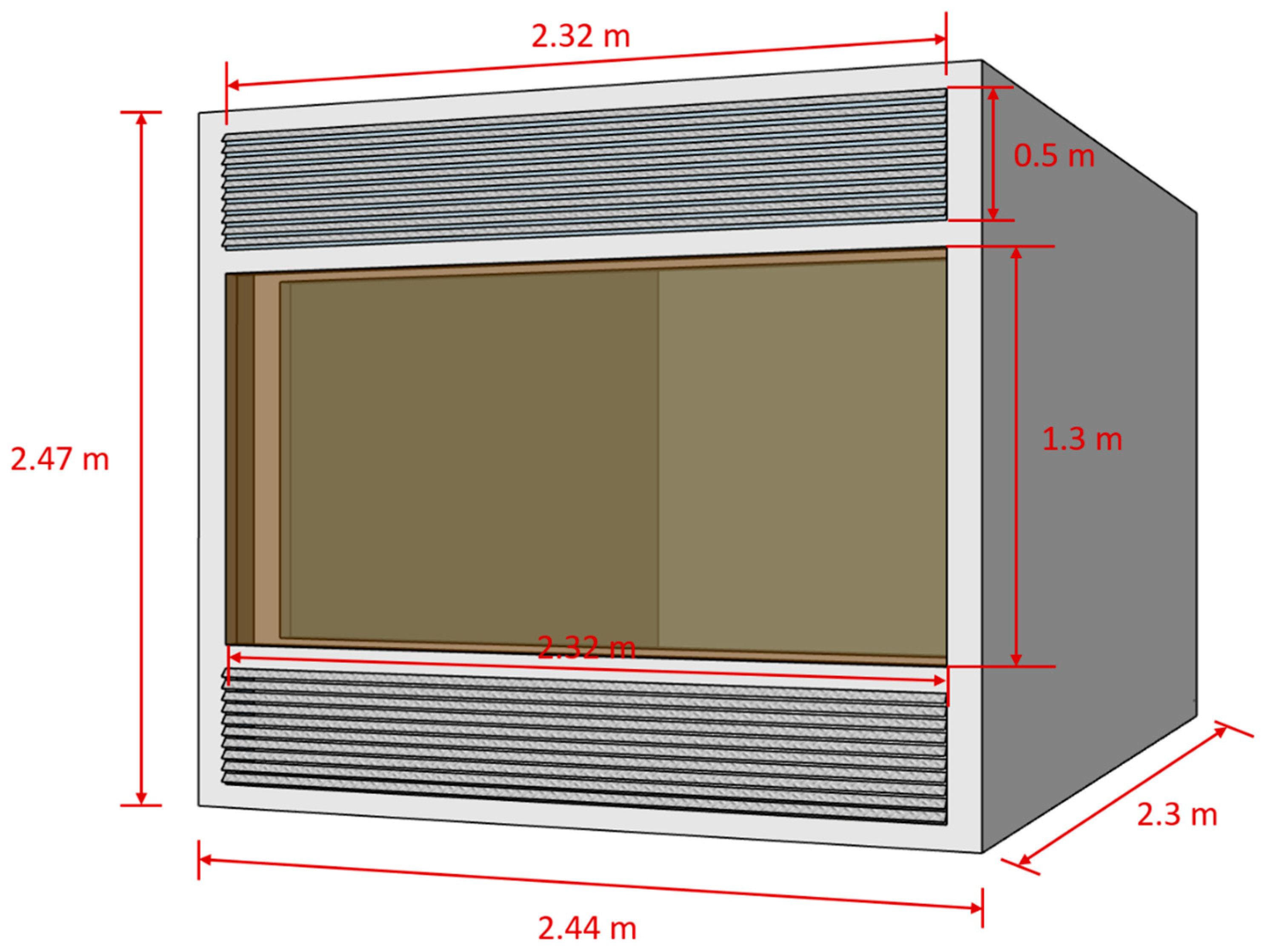
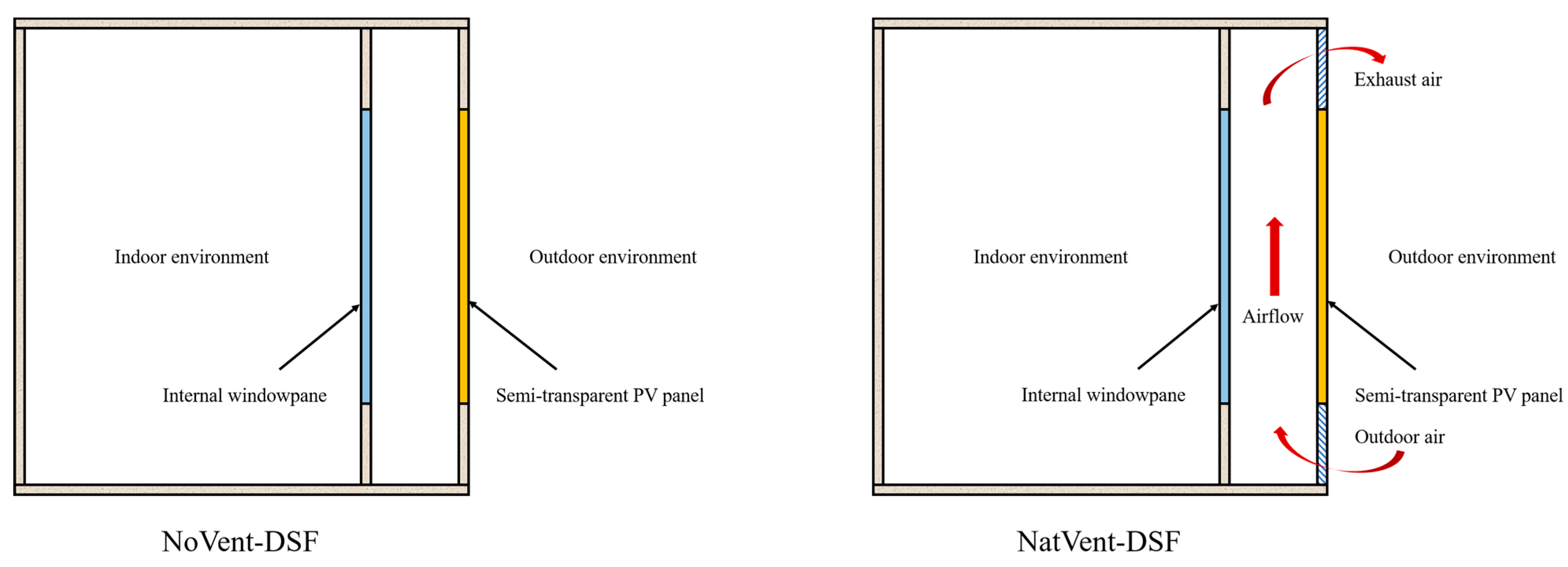
Overall, this study looks into two objectives—discomfort hours and energy (net thermal) consumption—for the office module on a yearly basis. Therefore, the optimal values of the most important design parameters could be determined using the method of Pareto optimality [36], which is widely used in the optimisation of multiple objectives for the performance of buildings and building energy systems [37,38,39,40,41]. Fundamentally, Pareto optimality deals with multi-objective functions that are to be either minimised or maximised, while a scenario of two objective functions can be illustrated in Figure 1.
The proposed study attempted to minimise both discomfort hours (f1) and energy consumption (f2). Given that there were 7 variations (including the original value) for Uin and SHGCout, respectively, so there were 49 solutions for the two contradictory objectives f1 and f2 for each orientation. Figure 1 shows a set of solutions including dominated and non-dominated solutions; the non-dominated solutions lying on the “Pareto front” are the most interesting solutions, where the optimal solution comes from [38]. The shortest distance of the non-dominated solution to the “ideal point” is deemed to be the optimal solution; the ‘ideal point’ is unattainable because both objectives cannot be minimised simultaneously due to their conflicting nature [38]. The distance can be determined as [38]:
d ( x ) = [ f 1 ( x ) m i n ( f 1 ) ] 2 + [ f 2 ( x ) m i n ( f 2 ) ] 2
where x is the design variable corresponding to a Uin and SHGCout among the 49 solutions, f1(x) is the objective function 1 (that is, discomfort hours), f2(x) is the objective function 2 (that is, energy consumption), min(f1) is the minimum value of the objective function 1 among the 49 solutions, and min(f2) is the minimum value of the objective function 2 among the 49 solutions.

2.3. BIPV-DSF Model

The validated BIPV-DSF model in TRNSYS from our previous research [28,29] was used for the simulation. The model was a single-room office module with a BIPV-DSF based on a real building test bed developed by Peng et al. [20], which could be used in the two desired operation modes for ventilation: Non-Ventilated BIPV-DSF (NoVent-DSF) and Naturally-Ventilated BIPV-DSF (NatVent-DSF). Specifically, the office module had a double-skin façade structure, where an air cavity (0.4 m of depth) was located in between the external and internal layers of the façade, allowing for the operation of the different ventilation modes through the ventilation louvres; a semi-transparent PV panel and a float glass served as the respective external and internal windowpanes. TRNFlow, an external simulation engine of TRNSYS, was used to simulate the natural ventilation through the air cavity. Figure 2 and Figure 3, respectively, illustrate the proposed BIPV-DSF office module with dimensions (the internal and external window dimensions were identical) and the two BIPV-DSF typologies, while their characteristics are further described in Table 4.
In addition to the important design parameters (variables), other parameters such as occupation information, thermal loads, building fabric other than the DSF, and building services systems for the BIPV-DSF office module were designed with fixed values (constants), as this study was focused solely on the behaviour of the BIPV-DSF. These constant values are specified in Table 5. To simplify the modelling processes, the discomfort hours calculation was based on a whole year of 8760 h rather than the whole year’s operating hours (that is, 2400 h).
Furthermore, a perovskite solar cell-based external windowpane was used in the optimisation in part due to its high electric power conversion efficiency in comparison with the other types of PV cells demonstrated in our previous studies [28,29]. Although the amorphous silicon solar cell, compared with other solar cell options, was determined as the most appropriate option for the high-humidity summer and warm winter climate (Darwin) in regard to the indoor thermal comfort, the discrepancy in indoor thermal comfort performance among all the PV options investigated was very slight. Overall, the perovskite-based solar cell possessed the best performance in controlling indoor thermal comfort as well as thermal energy consumption for the BIPV-DSF. Table 6 presents both thermal and optical properties of the selected semi-transparent perovskite PV panel.

3. Results and Discussion

In this study, the design solutions of the BIPV-DSF in relation to indoor thermal comfort and net thermal energy consumption were refined by optimising the most important design parameters. The results of the optimisation are presented and discussed through an integral analysis of both objective functions based on Pareto optimality in the following sections.

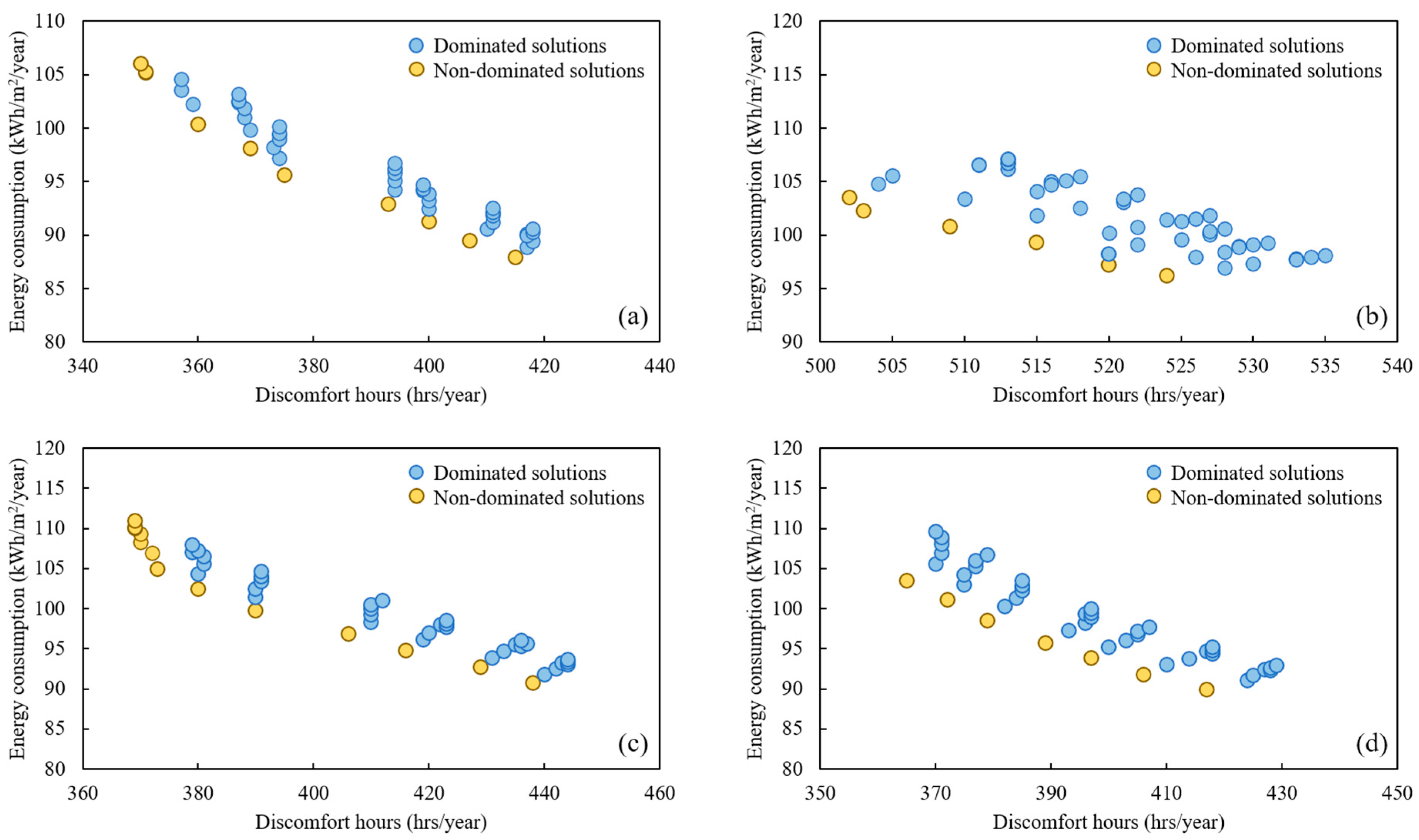
3.1. Optimising BIPV-DSF for High-Humidity Summer and Warm Winter Climate (Darwin)

Figure 4 shows the trade-off between the annual discomfort hours and net thermal energy consumption based on the variations of the most important design parameters (Uin and SHGCout) for the NatVent-DSF under the year-round high-humidity summer and warm winter climate (Darwin), where the four orientations were considered. Fundamentally, the optimal solution was determined using the Equation (7) for the scenarios of different orientations. For example, when the BIPV-DSF faced due north, the optimal solution refers to the non-dominated solution point where the respective values of Uin and SHGCout were 5.16 W/m2K and 0.81; in this case, the number of discomfort hours was 360, while the energy consumption (net thermal) was about 100.37 kWh/m2.
In addition, a set of outcomes for the optimal solution among the 49 solutions for the BIPV-DSF (NatVent-DSF) with different orientations is presented in Table 7, which indicates the values of the various parameters of an optimal solution including the two objectives (f1(x) and f2(x)), minimum values of both objectives (min(f1) and min(f2)), the shortest distance of the optimal solution (non-dominated) to the “ideal point” (d(x)min), and the optimal values of the most important design parameters—Uin and SHGCout. Basically, 5.16 W/m2K for Uin and 0.81 for SHGCout were optimal values for most orientation scenarios of the BIPV-DSF within the given solution space, except for the east-facing scenario where the optimal Uin was 5.53 W/m2K.

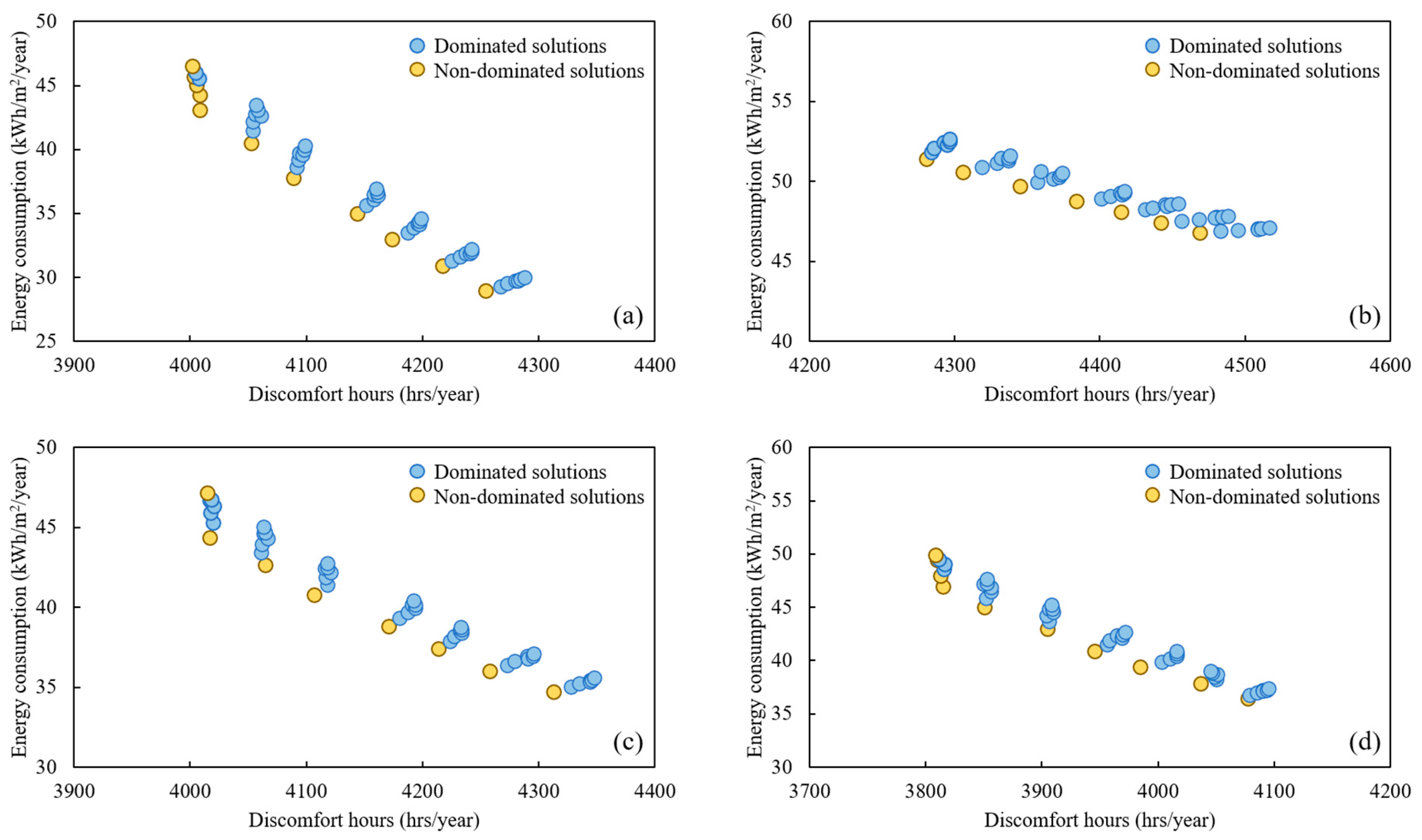
3.2. Optimising BIPV-DSF for Warm Temperate Climate (Sydney)

Given that both NatVent-DSF and NoVent-DSF were the most appropriate ventilation modes of the BIPV-DSF for the hot and cold months, respectively, in the warm temperate climate (Sydney), where the hot months fall from September to May while the cold months fall from June to August, the optimisation should take into account the two ventilation modes for the BIPV-DSF, while the optimal Uin and SHGCout should be unique because the window components of the BIPV-DSF cannot be substituted in reality. As can be observed in Figure 5, the Pareto front is indicated based on the non-dominated solutions (the yellow dots) within the given solution space for the combined NatVent-DSF and NoVent-DSF operations across the year, which is apparent although both clusters of dominated and non-dominated solutions are not dispersed to each other to a large extent for all of the scenarios of orientation.
Table 8 shows the details of the optimal solutions for the BIPV-DSF for different orientations in Sydney. Apparently, 5.87 W/m2K for Uin and 0.81 for SHGCout were optimal values for most orientation scenarios of the BIPV-DSF among the given feasible solutions, except for the south-facing scenario where the optimal Uin was 5.16 W/m2K. This was possibly due to the relatively low sun exposure when the orientation of the BIPV-DSF was fixed to due south; in this case, a lower Uin can reduce the heating demand during cold months and therefore reduce the overall thermal energy consumption. By comparison, it did not make a notable difference in thermal performance for the BIPV-DSF facing north or south in Darwin, as it is closer to the equator. Furthermore, a significantly high number of discomfort hours can be noticed for all the scenarios of Sydney, because such a crowded office module can impact greatly on its indoor thermal comfort [49]. However, this issue did not affect the design parameter optimisation within the given solution space.

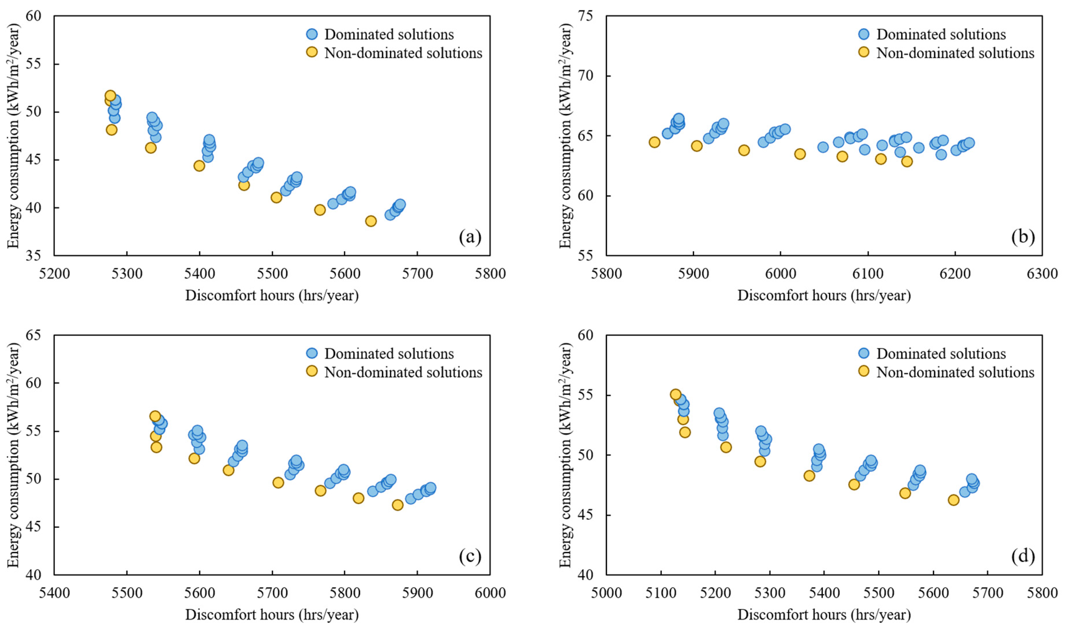
3.3. Optimising BIPV-DSF for Cool Temperate Climate (Canberra)

Same as in the case of Sydney, both NoVent-DSF and NatVent-DSF were selected for the Canberra case’s optimisation and the optimal values of the most important design parameters were unique. Specifically, in this case, the NoVent-DSF mode was applied to the cold months (falling from June to August), while the NatVent-DSF was applied to the hot months (falling from September to May). As shown in Figure 6, the Pareto front for the corresponding BIPV-DSF orientation scenario can be found by indicating the non-dominated solutions through the compact distribution of the feasible solutions.
Furthermore, the details of the optimal solution for the BIPV-DSF for different orientations in Canberra are given in Table 9, which shows the exact same optimal Uin and SHGCout values as that of the Sydney case; that is, Uin of 5.87 W/m2K and SHGCout of 0.81 were optimal values for the most orientation scenarios of the BIPV-DSF within the solution space, except for the south-facing scenario where the optimal Uin was 5.16 W/m2K due to the low sun exposure. Although a large number of discomfort hours also can be found for Canberra’s scenarios because of the small-sized office module, the optimal values of Uin and SHGCout were determined explicitly. In general, the SHGCout was supposed to be higher for the BIPV-DSF under all the three climate zones. Furthermore, a lower Uin of the BIPV-DSF was desired for the hot climate (Darwin), while the BIPV-DSF with a higher Uin was expected for both cool temperate (Canberra) and warm temperate (Sydney) climates.

4. Conclusions

This paper presents the optimisation of a BIPV-DSF applied to an office module for achieving the best performance of thermal energy conservation and indoor thermal comfort for the office in the context of three distinctive Australian climate zones. In terms of two different ventilation modes of the BIPV-DSF, namely naturally-ventilated and non-ventilated BIPV-DSFs, the following most important design parameters of the BIPV-DSF in the four cardinal directions (north, south, east, and west) were further optimised using the Pareto optimality method:
  • Thermal transmittance of internal window of the BIPV-DSF (Uin);
  • Solar heat gain coefficient of external window of the BIPV-DSF (SHGCout).
Based on the optimisation results presented for the three climate zones, the respective optimal design solutions of the BIPV-DSF-equipped office module among a set of feasible solutions can be summarised as follows:
  • In the high-humidity summer and warm winter climate zone (Darwin): naturally-ventilated BIPV-DSF with a semi-transparent perovskite-based PV glazing either facing north, south or west being utilised throughout the year. In this case, a Uin of 5.16 W/m2K and a SHGCout of 0.81 are optimum; while the Uin and SHGCout should be 5.53 W/m2K and 0.81, respectively, when the BIPV-DSF is east-oriented.
  • In the warm temperate climate zone (Sydney): a semi-transparent perovskite-based PV glazed BIPV-DSF facing north, east and west should be non-ventilated and naturally-ventilated during the cold and hot months, respectively. In this case, a Uin of 5.87 W/m2K and SHGCout of 0.81 are optimum. However, the Uin and SHGCout should be 5.16 W/m2K and 0.81, respectively, when the BIPV-DSF is south-oriented.
  • In the cool temperate climate (Canberra): a semi-transparent perovskite-based PV glazed BIPV-DSF facing north, east and west should be operated as non-ventilated and naturally-ventilated modes, respectively, during the cold and hot months. In this case, a Uin of 5.87 W/m2K and SHGCout of 0.81 are optimum, while the respective Uin and SHGCout should be 5.16 W/m2K and 0.81 when the BIPV-DSF is facing south.
However, the optimisation presented in this paper was confined to a given solution space for both Uin and SHGCout, which was based on the International Glazing Database in the simulation programme (TRNSYS) used during the course of the study. Future research is needed to investigate a bigger database of the window components for the BIPV-DSF and hence further refine the optimisation. On the other hand, a larger office building may be considered for the future study so as to reduce the excess number of discomfort hours from the crowded office module. In addition, further study on a multi-storey office building will also help understand BIPV-DSF performance in the real world.

Author Contributions

Writing—original draft preparation, S.Y.; methodology, S.Y., F.F., A.S. and D.P.; formal analysis, S.Y.; writing—review and editing, S.Y., F.F., A.S. and D.P.; supervision, F.F., A.S. and D.P. All authors have read and agreed to the published version of the manuscript.

Funding

This research received no external funding.

Data Availability Statement

The authors confirm that the data supporting the findings of this study are available within the article.

Conflicts of Interest

The authors declare no conflict of interest.

Nomenclature

Symbols
APV panel exposed area [m2]
d(x)minshortest distance of non-dominated solution to the “ideal point” [-]
EHexceedance hours or total discomfort hours [-]
f1(x)objective function 1 [hrs/year]
f2(x)objective function 2 [kWh/m2/year]
GTtotal incident solar radiation on PV panel surface [kW/m2]
Hdisca discomfort hour [-]
IAMincidence angle modifier [-]
min(f1)minimum value of objective function 1 [hrs/year]
min(f2)minimum value of objective function 2 [kWh/m2/year]
PPVPV electric power production [kW]
qcomb,s,icombined convective and radiative heat flux in the space [kW]
qcomb,s,ocombined convective and radiative heat flux to the surface [kW]
qs,iconductive heat flux from the wall at the inside surface [kW]
qs,oconductive heat flux into the wall at the outside surface [kW]
Ss,isolar radiation and long-wave radiation generated from internal objects [kW]
Ss,osolar radiation from external surfaces [kW]
SHGCsolar heat gain coefficient [-]
SHGCoutsolar heat gain coefficient of external window of BIPV-DSF [-]
U-valuethermal transmittance [W/m2K]
Uinthermal transmittance of internal window of BIPV-DSF [W/m2K]
Uoutthermal transmittance of external window of BIPV-DSF [W/m2K]
Wallgainuser defined energy flow to inside wall or window surfaces [kW]
xa design variable [-]
Greek symbols
ηPVPV power conversion efficiency [%]
ταproduct of PV panel’s transmittance and absorptance [-]
Subscripts
nnormal incidence angle of solar radiation
Abbreviations
BIPVbuilding-integrated photovoltaic
BIPV-DSFbuilding-integrated photovoltaic double-skin facade
CdTecadmium telluride
CIGScopper indium gallium selenide
DSFdouble-skin facade
NatVent-DSFnaturally-ventilated BIPV-DSF
NoVent-DSFnon-ventilated BIPV-DSF
PMVPredicated Mean Vote
PVphotovoltaic
SCoPseasonal coefficient of performance
STCstandard test condition

References

  1. Al-Humaiqani, M.M.; Al-Ghamdi, S.G. The built environment resilience qualities to climate change impact: Concepts, frameworks, and directions for future research. Sustain. Cities Soc. 2022, 80, 103797. [Google Scholar] [CrossRef]
  2. Moncaster, A. The Impact of the Built Environment on Climate Change—And of Climate Change on the Built Environment. Design for Sustainability. 2021. Available online: http://www.open.ac.uk/blogs/design/the-impact-of-the-built-environment-on-climate-change-and-of-climate-change-on-the-built-environment/#:~:text=Why%20is%20the%20built%20environment,than%20any%20other%20individual%20sector (accessed on 5 June 2022).
  3. Ritchie, H.; Roser, M.; Rosado, P. CO2 and Greenhouse Gas Emissions. 2020. Available online: https://ourworldindata.org/co2-and-other-greenhouse-gas-emissions (accessed on 5 June 2022).
  4. Malyan, S.K.; Kumar, A.; Baram, S.; Kumar, J.; Singh, S.; Kumar, S.S.; Yadav, A.N. Role of Fungi in Climate Change Abatement through Carbon Sequestration, in Recent Advancement in White Biotechnology through Fungi; Springer: Berlin/Heidelberg, Germany, 2019; pp. 283–295. [Google Scholar]
  5. Tricoire, J.-P. Rethinking Buildings is a Climate Imperative: Here’s What to Focus on. 2022. Available online: https://www.weforum.org/agenda/2022/05/rethinking-buildings-is-a-climate-imperative-here-s-what-to-focus-on/ (accessed on 5 June 2022).
  6. Jafarpur, P.; Berardi, U. Effects of climate changes on building energy demand and thermal comfort in Canadian office buildings adopting different temperature setpoints. J. Build. Eng. 2021, 42, 102725. [Google Scholar] [CrossRef]
  7. Yang, L.; Yan, H.; Lam, J.C. Thermal comfort and building energy consumption implications—A review. Appl. Energy 2014, 115, 164–173. [Google Scholar] [CrossRef]
  8. Holmes, M.J.; Hacker, J.N. Climate change, thermal comfort and energy: Meeting the design challenges of the 21st century. Energy Build. 2007, 39, 802–814. [Google Scholar] [CrossRef]
  9. Mirrahimi, S.; Mohamed, M.F.; Haw, L.C.; Ibrahim, N.L.N.; Yusoff, W.F.M.; Aflaki, A. The effect of building envelope on the thermal comfort and energy saving for high-rise buildings in hot–humid climate. Renew. Sustain. Energy Rev. 2016, 53, 1508–1519. [Google Scholar] [CrossRef]
  10. Ghaffarianhoseini, A.; Ghaffarianhoseini, A.; Berardi, U.; Tookey, J.; Li, D.H.W.; Kariminia, S. Exploring the advantages and challenges of double-skin façades (DSFs). Renew. Sustain. Energy Rev. 2016, 60, 1052–1065. [Google Scholar] [CrossRef]
  11. Bui, D.-K.; Nguyen, T.N.; Ghazlan, A.; Ngo, N.T.; Ngo, T.D. Enhancing building energy efficiency by adaptive façade: A computational optimization approach. Appl. Energy 2020, 265, 114797. [Google Scholar] [CrossRef]
  12. Attia, S.; Bilir, S.; Safy, T.; Struck, C.; Loonen, R.; Goia, F. Current trends and future challenges in the performance assessment of adaptive façade systems. Energy Build. 2018, 179, 165–182. [Google Scholar] [CrossRef]
  13. Attia, S.; Lioure, R.; Declaude, Q. Future trends and main concepts of adaptive facade systems. Energy Sci. Eng. 2020, 8, 3255–3272. [Google Scholar] [CrossRef]
  14. Attia, S.; Bertrand, S.; Cuchet, M.; Yang, S.; Tabadkani, A. Comparison of Thermal Energy Saving Potential and Overheating Risk of Four Adaptive Façade Technologies in Office Buildings. Sustainability 2022, 14, 6106. [Google Scholar] [CrossRef]
  15. Yang, S.; Fiorito, F.; Prasad, D.; Sproul, A. Numerical Simulation Modelling of Building-Integrated Photovoltaic Double-Skin Facades. In Recent Advances in Numerical Simulations; Bulnes, F., Hessling, J.P., Eds.; IntechOpen: London, UK, 2021; pp. 61–75. [Google Scholar]
  16. Xu, C.; Ma, X.; Francis Yu, C.W. Photovoltaic double-skin façade: A combination of active and passive utilizations of solar energy. Indoor Built Environ. 2019, 28, 1013–1017. [Google Scholar] [CrossRef]
  17. Bloem, J.J.; Lodi, C.; Cipriano, J.; Chemisana, D. An outdoor Test Reference Environment for double skin applications of Building Integrated PhotoVoltaic Systems. Energy Build. 2012, 50, 63–73. [Google Scholar] [CrossRef]
  18. Gaillard, L.; Giroux-Julien, S.; Ménézo, C.; Pabiou, H. Experimental evaluation of a naturally ventilated PV double-skin building envelope in real operating conditions. Sol. Energy 2014, 103, 223–241. [Google Scholar] [CrossRef]
  19. Saadon, S.; Gaillard, L.; Giroux-Julien, S.; Ménézo, C. Simulation study of a naturally-ventilated building integrated photovoltaic/thermal (BIPV/T) envelope. Renew. Energy 2016, 87, 517–531. [Google Scholar] [CrossRef]
  20. Peng, J.; Lu, L.; Yang, H. An experimental study of the thermal performance of a novel photovoltaic double-skin facade in Hong Kong. Sol. Energy 2013, 97, 293–304. [Google Scholar] [CrossRef]
  21. Peng, J.; Curcija, D.C.; Lu, L.; Selkowitz, S.E.; Yang, H.; Zhang, W. Numerical investigation of the energy saving potential of a semi-transparent photovoltaic double-skin facade in a cool-summer Mediterranean climate. Appl. Energy 2016, 165, 345–356. [Google Scholar] [CrossRef]
  22. Ioannidis, Z.; Buonomano, A.; Athienitis, A.K.; Stathopoulos, T. Modeling of double skin façades integrating photovoltaic panels and automated roller shades: Analysis of the thermal and electrical performance. Energy Build. 2017, 154, 618–632. [Google Scholar] [CrossRef]
  23. Fatnassi, S.; Abidi-Saad, A.; Ben Maad, R.; Polidori, G. Numerical study of spacing and alternation effects of parietal heat sources on natural convection flow in a DSF-channel: Application to BIPV. Heat Mass Transf. 2018, 54, 3617–3629. [Google Scholar] [CrossRef]
  24. Wang, C.; Peng, J.; Li, N.; Wang, M.; Li, X. Study on the operation strategy of ventilated photovoltaic windows in hot-summer and cold-winter zone in China. Procedia Eng. 2017, 205, 2092–2099. [Google Scholar] [CrossRef]
  25. Shakouri, M.; Ghadamian, H.; Noorpoor, A. Quasi-dynamic energy performance analysis of building integrated photovoltaic thermal double skin façade for middle eastern climate case. Appl. Therm. Eng. 2020, 179, 115724. [Google Scholar] [CrossRef]
  26. Yang, S.; Fiorito, F.; Sproul, A.; Prasad, D. Studies on Optimal Application of Building-Integrated Photovoltaic/Thermal Facade for Commercial Buildings in Australia. In Proceedings of the SWC2017/SHC2017, Abu Dhabi, United Arab Emirates, 29 October–2 November 2017; pp. 1–10. [Google Scholar]
  27. Yang, S.; Fiorito, F.; Sproul, A.; Prasad, D. Study of building integrated photovoltaic/thermal double-skin facade for commercial buildings in Sydney, Australia. In Proceedings of the Final Conference of COST TU1403 “Adaptive Facades Network”, Lucerne, Switzerland, 26–27 November 2018. [Google Scholar]
  28. Yang, S.; Cannavale, A.; Prasad, D.; Sproul, A.; Fiorito, F. Numerical simulation study of BIPV/T double-skin facade for various climate zones in Australia: Effects on indoor thermal comfort. Build. Simul. 2018, 12, 51–67. [Google Scholar] [CrossRef]
  29. Yang, S.; Cannavale, A.; Di Carlo, A.; Prasad, D.; Sproul, A.; Fiorito, F. Performance assessment of BIPV/T double-skin façade for various climate zones in Australia: Effects on energy consumption. Sol. Energy 2020, 199, 377–399. [Google Scholar] [CrossRef]
  30. Roberts, F.; Yang, S.; Du, H.; Yang, R. Effect of semi-transparent a-Si PV glazing within double-skin façades on visual and energy performances under the UK climate condition. Renew. Energy 2023, 207, 601–610. [Google Scholar] [CrossRef]
  31. Yang, S.; Fiorito, F.; Prasad, D.; Sproul, A.; Cannavale, A. A sensitivity analysis of design parameters of BIPV/T-DSF in relation to building energy and thermal comfort performances. J. Build. Eng. 2021, 41, 102426. [Google Scholar] [CrossRef]
  32. Elsharkawy, H.; Zahiri, S. The significance of occupancy profiles in determining post retrofit indoor thermal comfort, overheating risk and building energy performance. Build. Environ. 2020, 172, 106676. [Google Scholar] [CrossRef]
  33. Kumar, A.; Suman, B.M. Experimental evaluation of insulation materials for walls and roofs and their impact on indoor thermal comfort under composite climate. Build. Environ. 2013, 59, 635–643. [Google Scholar] [CrossRef]
  34. Liu, M.; Heiselberg, P.K.; Antonov, Y.I.; Mikkelsen, F.S. Parametric analysis on the heat transfer, daylight and thermal comfort for a sustainable roof window with triple glazing and external shutter. Energy Build. 2019, 183, 209–221. [Google Scholar] [CrossRef]
  35. Song, B.; Bai, L.; Yang, L. Analysis of the long-term effects of solar radiation on the indoor thermal comfort in office buildings. Energy 2022, 247, 123499. [Google Scholar] [CrossRef]
  36. Stiglitz, J.E. Pareto optimality and competition. J. Financ. 1981, 36, 235–251. [Google Scholar] [CrossRef]
  37. Maltais, L.-G.; Gosselin, L. Daylighting ‘energy and comfort’ performance in office buildings: Sensitivity analysis, metamodel and pareto front. J. Build. Eng. 2017, 14, 61–72. [Google Scholar] [CrossRef]
  38. Bre, F.; Fachinotti, V.D. A computational multi-objective optimization method to improve energy efficiency and thermal comfort in dwellings. Energy Build. 2017, 154, 283–294. [Google Scholar] [CrossRef]
  39. Ameur, M.; Kharbouch, Y.; Mimet, A. Optimization of passive design features for a naturally ventilated residential building according to the bioclimatic architecture concept and considering the northern Morocco climate. Build. Simul. 2020, 13, 677–689. [Google Scholar] [CrossRef]
  40. Chi, F.A.; Xu, Y. Building performance optimization for university dormitory through integration of digital gene map into multi-objective genetic algorithm. Appl. Energy 2022, 307, 118211. [Google Scholar] [CrossRef]
  41. Wijeratne, W.M.P.U.; Samarasinghalage, T.I.; Yang, R.J.; Wakefield, R. Multi-objective optimisation for building integrated photovoltaics (BIPV) roof projects in early design phase. Appl. Energy 2022, 309, 118476. [Google Scholar] [CrossRef]
  42. Pal, S.K.; Alanne, K.; Jokisalo, J.; Siren, K. Energy performance and economic viability of advanced window technologies for a new Finnish townhouse concept. Appl. Energy 2016, 162, 11–20. [Google Scholar] [CrossRef]
  43. Chen, F.; Wittkopf, S.K.; Ng, P.K.; Du, H. Solar heat gain coefficient measurement of semi-transparent photovoltaic modules with indoor calorimetric hot box and solar simulator. Energy Build. 2012, 53, 74–84. [Google Scholar] [CrossRef]
  44. Lie, S.; Bruno, A.; Wong, L.H.; Etgar, L. Semitransparent Perovskite Solar Cells with >13% Efficiency and 27% Transperancy Using Plasmonic Au Nanorods. ACS Appl. Mater. Interfaces 2022, 14, 11339–11349. [Google Scholar] [CrossRef]
  45. ASHRAE. Standard 55. In Thermal Environmental Conditions for Human Occupancy; American Society of Heating, Refrigerating and Air-Conditioning Engineers: Atlanta, GA, USA, 2017. [Google Scholar]
  46. TRNSYS. TRNSYS 17—Volume 5—Multizone Building Modelling with Type56 and TRNBuild; Solar Energy Laboratory, University of Wisconsin-Madison: Madison, WI, USA, 2005. [Google Scholar]
  47. Thermal Energy System Specialists. TESSLibs 17 Component Libraries for the TRNSYS Simulation Environment; HVAC Library Mathematical Reference, Ed.; Thermal Energy System Specialists, LLC: Madison, WI, USA, 2013. [Google Scholar]
  48. Australian Building Codes Board. Building Code of Australia, in National Construction Code Volume One; Australian Building Codes Board: Canberra, Australia, 2019. [Google Scholar]
  49. Amasuomo, T.; Amasuomo, J. Perceived Thermal Discomfort and Stress Behaviours Affecting Students’ Learning in Lecture Theatres in the Humid Tropics. Buildings 2016, 6, 18. [Google Scholar] [CrossRef]
Figure 1. Pareto front for two contradictory objectives.
Buildings 13 01096 g001
Figure 2. Front view of the office module with BIPV-DSF.
Buildings 13 01096 g002
Figure 3. BIPV-DSF typologies in terms of operation modes for ventilation.
Buildings 13 01096 g003
Figure 4. Trade-off between annual discomfort hours and net thermal energy consumption with the variations of Uin and SHGCout for NatVent-DSF (all year round, Darwin) for different orientations: (a) North, (b) South, (c) East, and (d) West.
Buildings 13 01096 g004
Figure 5. Trade-off between annual discomfort hours and net thermal energy consumption with the variations of Uin and SHGCout for NoVent-DSF (cold months, Sydney) and NatVent-DSF (hot months, Sydney) for different orientations: (a) North, (b) South, (c) East, and (d) West.
Buildings 13 01096 g005
Figure 6. Trade-off between annual discomfort hours and net thermal energy consumption with the variations of Uin and SHGCout for NoVent-DSF (cold months, Canberra) and NatVent-DSF (hot months, Canberra) for different orientations: (a) North, (b) South, (c) East, and (d) West.
Buildings 13 01096 g006
Table 1. Summary of most important design parameters based on sensitivity analysis.
Design ParameterAbbreviationType of Parameter
Thermal transmittance (U-value) of internal window of the BIPV-DSFUinMaterial-based
Solar heat gain coefficient (SHGC) of external window of the BIPV-DSFSHGCoutMaterial-based
Table 2. Ventilation modes used for different climate conditions [28,29].
High Humidity Summer and Warm Winter Climate
(Represented by Darwin)
Warm Temperate Climate
(Represented by Sydney)
Cool Temperate Climate
(Represented by Canberra)
Ventilation modeNatural ventilation (whole year)Natural ventilation (hot months)
Non ventilation (cold months)
Natural ventilation (hot months)
Non ventilation (cold months)
Table 3. Variation space of the most important parameters for optimisation.
ParameterUnitOriginal ValueVariation Range/Values
UinW/m2K5.685.16, 5.39, 5.53, 5.68, 5.73, 5.8, 5.87
SHGCout-0.6240.432, 0.495, 0.557, 0.624, 0.683, 0.747, 0.811
Table 4. Characteristics of the two BIPV-DSF typologies.
Operation Mode for VentilationCharacteristics
NoVent-DSF
-
No air exchange between occupied zone, air cavity, and outdoor environment
-
No ventilation within air cavity
NatVent-DSF
-
No air exchange between occupied zone and air cavity
-
Stack effect driven natural ventilation between air cavity and outdoor environment
Table 5. Design parameters with constant values.
ParameterValueReference
Operating hours8 a.m.~6 p.m.Typical setting for offices
Heat gain from occupant (assuming there was one person in the room)150 W/personTypical value for offices
Heat gain from computer25 W/m2Typical value for offices
Heat gain from lights5 W/m2Typical value for offices
U-value of external wall0.51 W/m2KBuilding Code of Australia for office buildings [48]
U-value of roof0.24 W/m2KBuilding Code of Australia for office buildings [48]
Slab on groundAdiabaticDeemed as an adiabatic surface
Heating (reversible heat pump system)SCoP: 3.5
Setpoint temperature: 22 °C
Previous research [29]
Cooling (reversible heat pump system)SCoP: 2.5
Setpoint temperature: 26 °C
Previous research [29]
Table 6. Thermal and optical properties—semi-transparent perovskite PV panel.
ParameterValues
Visible light transmittance37.5%
Visible light reflectance (front)4.0%
Visible light reflectance (back)4.0%
Solar transmittance (front)33.2%
Solar transmittance (back)33.2%
Solar reflectance (front)3.5%
Solar reflectance (back)3.5%
U-value5.59 W/m2K
Emissivity0.89
PV efficiency (under STC)6.64%
Temperature coefficient of power−0.3%/°C
Table 7. Summary of numerical outcomes for the optimal solutions—Darwin.
f1(x), Hoursmin(f1), Hoursf2(x), kWh/m2min(f2), kWh/m2d(x)minUin, W/m2KSHGCout
North360350100.3787.915.995.160.81
South502502103.5496.24152.85.160.81
East370369108.3190.7828.585.530.81
West365365103.589.9521.645.160.81
Table 8. Summary of numerical outcomes for the optimal solutions—Sydney.
f1(x), Hoursmin(f1), Hoursf2(x), kWh/m2min(f2), kWh/m2d(x)minUin, W/m2KSHGCout
North4002400246.5128.923652.235.870.81
South4281428151.4146.783931.175.160.81
East4015401547.1134.723665.235.870.81
West3809380949.936.413459.215.870.81
Table 9. Summary of numerical outcomes for the optimal solutions—Canberra.
f1(x), Hoursmin(f1), Hoursf2(x), kWh/m2min(f2), kWh/m2d(x)minUin, W/m2KSHGCout
North5277527751.7138.654927.135.870.81
South5855585564.4762.885505.055.160.81
East5539553956.5947.275189.095.870.81
West5127512755.0446.274777.115.870.81
Disclaimer/Publisher’s Note: The statements, opinions and data contained in all publications are solely those of the individual author(s) and contributor(s) and not of MDPI and/or the editor(s). MDPI and/or the editor(s) disclaim responsibility for any injury to people or property resulting from any ideas, methods, instructions or products referred to in the content.

