Article

Numerical Design of the Roof Structure of a Vehicle Charging Carport Based on the Dragonfly Wing Grid Pattern

Architecture and Design College, Nanchang University, Nanchang 330031, China
*
Author to whom correspondence should be addressed.
Buildings 2023, 13(4), 1071; https://doi.org/10.3390/buildings13041071
Submission received: 26 February 2023 / Revised: 12 April 2023 / Accepted: 13 April 2023 / Published: 18 April 2023
(This article belongs to the Special Issue Advances in the Behaviour of Steel Structures)

Abstract

:
The realization of the global “Double carbon” target is closely related to the energy-saving travel of human beings. Along with the increase in the number of new energy vehicles around the world, the number of new energy vehicle charging post carports has also increased. However, the collapse of the carport of the new energy vehicle charging post often occurs. The search for ways to optimize the carport structure construction and build a lighter and more stable charging post carport structure has become one of the hot spots in the new energy vehicle industry. Dragonfly wings have a comprehensive evolution in structure, form and function, and their stiffness, stability and resistance to deformation may be a potential solution to optimize the structure of the shed roof. Inspired by this, the study designs two new energy vehicle charging pile canopies based on the dragonfly wing mesh structure to enhance the loading capacity and structural stability of the canopies. The study firstly concludes that the dragonfly wing mesh can enhance the stiffness through experimental analysis, and simulates and models the structure based on the quadrilateral mesh wrinkling and hexagonal mesh arching in its mesh morphology, combined with the national design standard of the charging pile canopy. Studies on the numerical design experiment of the new energy vehicle charging station canopy model based on finite element software under different natural loads, the deflection of shed under the action of self-weight and the deflection, tensile stress and compressive stress under external load are analyzed, and the results show that: (1) The grid structure of the dragonfly wing bionic charging pile shed can optimize the stiffness of the car charging pile shed. (2) According to the wing structure, the test results of the shed roof structure under different working conditions are better than the national standard. (3) Compared with the vertical load, the transverse load of the arched membrane structure, which is represented by the charging pile shed of the new energy vehicle, is larger. (4) According to the stress point of the shed, the structure constraint of the shed can effectively reduce the pressure on the and share part of the load, which can enhance the stability of the shed. (5) In comparison with the displacement of common carport types, the bionic carport shows superior stability and durability. The new bionic carport structure proposed by the research, with stronger pressure bearing, smaller force deformation and lighter weight, is a kind of membrane structure for stable new energy vehicle charging pile carports, which will help further the optimization and promotion of the new energy vehicle industry.

1. Introduction

In the era of carbon neutrality, the utilization rate of new energy vehicles continues to rise, and the demand for new-energy-vehicle-supporting devices is increasing. Although the membrane structure shed of the new energy vehicle is widely used in modern urban buildings, the research on its overall bearing capacity is still limited, and the safety, stability and durability of the new energy vehicle (Nev) charging pile shed have become some of the concerns and worries; therefore, the innovative design of the steel frame structure of the membrane structure shed has become a hot spot in the new energy industry. Although the ubiquitous membrane structure charging pile canopy has the advantage of being economical and lightweight, it deforms or even collapses under the pressure of other external forces such as natural wind and snow loads. Current researchers have summarized a series of causes for the common accidents of membrane structures, including climate (strong winds, heavy rain, snow and a series of other natural disasters), human construction and design, and fatigue aspects of the grid structure [1,2,3,4,5]. How to effectively increase the structural stiffness of the membrane carport, imitating the grid structure of dragonfly wings for the bionic design of new energy vehicle charging post carports, may be a potential solution.
The earliest dragonfly fossils found by humans dates back 320 million years and are known as the “Flying Kings” of nature, and the study of dragonflies has also contributed to the development of human technology to a certain extent. The biggest difference between dragonflies and other insects is that they can fly freely in the sky, “hover” in the air and take off very quickly after stopping. According to research observations, dragonfly wings are an arched and wrinkled three-dimensional structure with certain folds in the main vein that taper towards the wing tip; in addition to this, the wings are also arched in both directions, which substantially enhances the stiffness of the wings and allows them to hover and take off quickly, showing that the arch structure is an important basis for dragonfly wings to perform their unique functions, and the reticulation of dragonfly wings allows for optimal wing stiffness and stability [6].
The unique web-like structure and three-dimensional wrinkled and arched structure of dragonfly wings enable them to fly extremely fast and withstand alternating stresses at certain frequencies and amplitudes with minimal energy consumption, thus also exhibiting superior fatigue resistance [7]. The different lattices of dragonfly wings form a robust three-dimensional truss-like configuration that not only reduces the energy required to vibrate the wings and relieves the pressure at the wingtips, but also allows the wingtips to flexibly adjust their angle and deformation when subjected to extreme impacts [8]. In addition, it was found that buildings using dragonfly wing structures were constructed with good stability and a high load capacity despite the fact that the buildings used very little construction material in the construction process [9]. Stefano Mintchev, inspired by insect wings, used a prestretched elastic membrane to present the structure’s dual-stiffness properties through origami, laying the foundation for the study of the stability of the reticulated structure of dragonfly wings [10]. Xiu-Juan Li used scanning electron microscopy to observe the surface morphology and microstructure of dragonfly wings and showed that dragonfly wing vein crossings and membranes form excellent spatial truss-like structures that inhibit the formation and propagation of fatigue cracks [11]. Therefore, based on existing theoretical research, this study explores the use of dragonfly wing truss structures, which utilize the special arching and wrinkling structure of dragonfly wings to alleviate most of the stress and pressure, as well as enhance the wing stiffness, and investigates the different mechanical stiffness and flexibility of dragonfly wing mesh networks. Combining this with a new energy charging station shelter, the aim is to design a completely new arched roof structure that can further improve the compressive strength of new energy vehicle charging station shelters.
Designing arched shell structures based on dragonfly wings is common in real-life, and grid-like buildings are also prevalent. However, how to make grid shell structures sustainable has attracted continuous attention from scholars. Dominika Bysiec studied the spherical structures of geodesic domes and proposed two plasticity methods to consume less building materials and reduce weight [12]. Tayfun Dede designed and optimized the size of small, medium and large truss dome structures constrained by frequency using newly developed metaheuristic algorithms (Rao-1, Rao-2 and Rao-3) and finite element analysis computer programs with the Orr–Sommerfeld algorithm and the stiffness matrix eigenvalue method [13]. S.O. Degertekin developed the parameter-free Jaya algorithm (PFJA) to solve eight classic truss weight minimization problems, demonstrating the superiority of the PFJA metaheuristic optimizer [14]. Shengqi Feng proposed an effective B-spline parameterization method for optimizing the layout of ribs in shell structures, avoiding cantilevered ribs [15]. Ana Pavlovic compared several design configurations of photovoltaic car roofs using static and modal analysis through finite element analysis. A representative roof model was established and a structure optimized with a four-directional mesh was applied to improve the stiffness of the solar car roof [16]. Ning Li optimized the lightweight design of the head pressure hull of an autonomous underwater vehicle (AUV) and found that a mesh sandwich structure shell is lighter than a solid shell and does not experience buckling deformation under given conditions [17]. Fengcheng Liu proposed an improved optimization method for mesh structures, in which bending strain energy was used as a constraint during the optimization process to obtain efficient mesh structures [18]. Based on the research and optimization of shell and mesh structures by many scholars, the feasibility of mesh shell structures in building structures has been proven. The optimization of a charging shed for electric vehicles with a biomimetic dragonfly wing mesh structure can further improve the stiffness and stability of the shed and has innovative significance. Through the research and experiments on the optimization of a charging shed for electric vehicles with a biomimetic dragonfly wing mesh structure, we can further explore and optimize the application of mesh shell structures, providing new ideas and directions for the development of building structures. At the same time, this study can provide practical support and help for the development and promotion of new energy vehicles, promoting low-carbon environmental protection and sustainable development.
Finite element software can be used to solve structural, fluid and electrical problems, and is applicable to a wide range of fields, such as bridges, buildings and heavy machinery. The OptiStruct finite element software mainly contains: a preprocessing module, a solution module and a postprocessing module. The types of analysis provided include: static analysis, transient analysis, modal analysis, harmonic analysis, spectral analysis, deflection and substructure, and the loads are divided into: displacement load, force or moment, surface load, etc. M.R.T. Arruda used finite element software to perform a nonlinear analysis of reinforced concrete frame construction and simulated concrete using a permanent strain damage model, proving its development potential [19]. Hussein M. Elsanadedy evaluated the risk of collapse of precast concrete numerically using the finite element method and established a finite element model with actual parameters [20]. For the nonuniform heating model in the structure under fire, Myriam R. Pallares-Muñoz proposed a new method using the Timoshenko beam-type finite element to represent the nonuniform temperature spatiotemporal field with the average temperature and two average values of the cross-sectional temperature gradient, capturing three-dimensional phenomena [21]. Pan Yu further improved the lateral performance of the mortise and tenon connection in the wooden structure by comparing the load-displacement curves of the hybrid finite element framework model at the top with those of the solid element model in ABAQUS, and the results confirmed that the gap in the MT connection was the main source of weakness in the transverse resistance of the frame [22]. Ashok Kumar Bagha tested the mechanical properties of the nanocomposites using finite element software and found that the addition of a small amount of nanofibers resulted in considerable improvement in the longitudinal modulus of the nanocomposites [23]. Kiran Dandekar performed 3D modeling of the human monkey fingertip and analyzed the deformation of the fingertip model under linear loading using finite element software [24]. Mohammad Zaid used the finite element method to measure the behavior of tunnels under static pressure and concluded through a finite element software simulation that, with the increase of the weathering index of surrounding rocks, the tunnel undergoes significant deformation [25]. Finite element analysis software has also been used by many scholars in the study and application of dragonfly wings; for example, Hou D used finite element software to model dragonfly wings and to compare aerodynamic and inertial forces [26]. Xu F used finite element software to build dragonfly wings and analyzed the excellent structural characteristics of dragonfly veins to design bionic car doors, showing better resistance to deformation and vibration [27]. Based on the above foundation, this study utilized the finite element software OptiStruct to model the bionic dragonfly wing structure of a new energy vehicle charging shed, and compared the displacement and stress of two designs under linear and nonlinear states. The deformation degree and specific position of the two sheds under different load conditions were observed in static analysis to further adjust the design.
The main focus of this study is to draw inspiration from biomimetic design, specifically the wings of dragonflies, to develop two different carport structures and explore ways to improve the load-bearing capacity of the arched structure. Finite element software was used to model and simulate two carport models based on quad mesh wrinkles and composite hexagonal arches. The results validated the effectiveness of the dragonfly wing mesh in increasing the stiffness of the roof of the new energy vehicle charging station canopy. The numerical analysis of the carport structure was divided into two parts to study the load performance and stability under extreme and normal operating conditions: the behavior of the overall canopy structure and the behavior of individual components. The first part mainly focused on the total stress and displacement of the canopy structure, considering variable loads such as live loads, wind loads and snow loads, and compared the linear and nonlinear solutions of different carport models. The second part of the local component support column mainly includes adding constraints to the carport model with the maximum stiffness, comparing the stiffness under four load conditions and comparing the deflection, tensile stress and compressive stress data under different working conditions, exploring the solution for improving the stiffness of the new energy vehicle charging pile carport structure. The application of the research results is mainly in guiding the optimization and improvement of the stability of the new energy vehicle charging pile carport structure and the long-term use of the carport. It is worth noting that research into the new energy vehicle charging pile carport construction material pipe diameter, wall thickness, shell thickness and how to choose the most appropriate size while saving cost has not been studied, while the selection of the building size still needs targeted research.

2. Research Objects and Methods

2.1. Research Objects

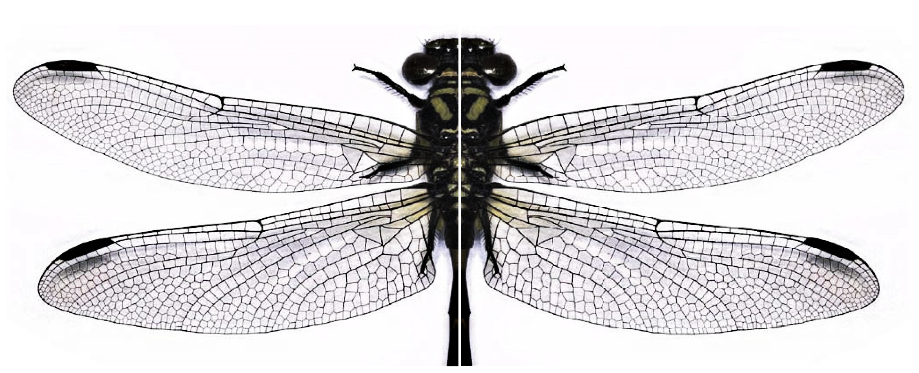
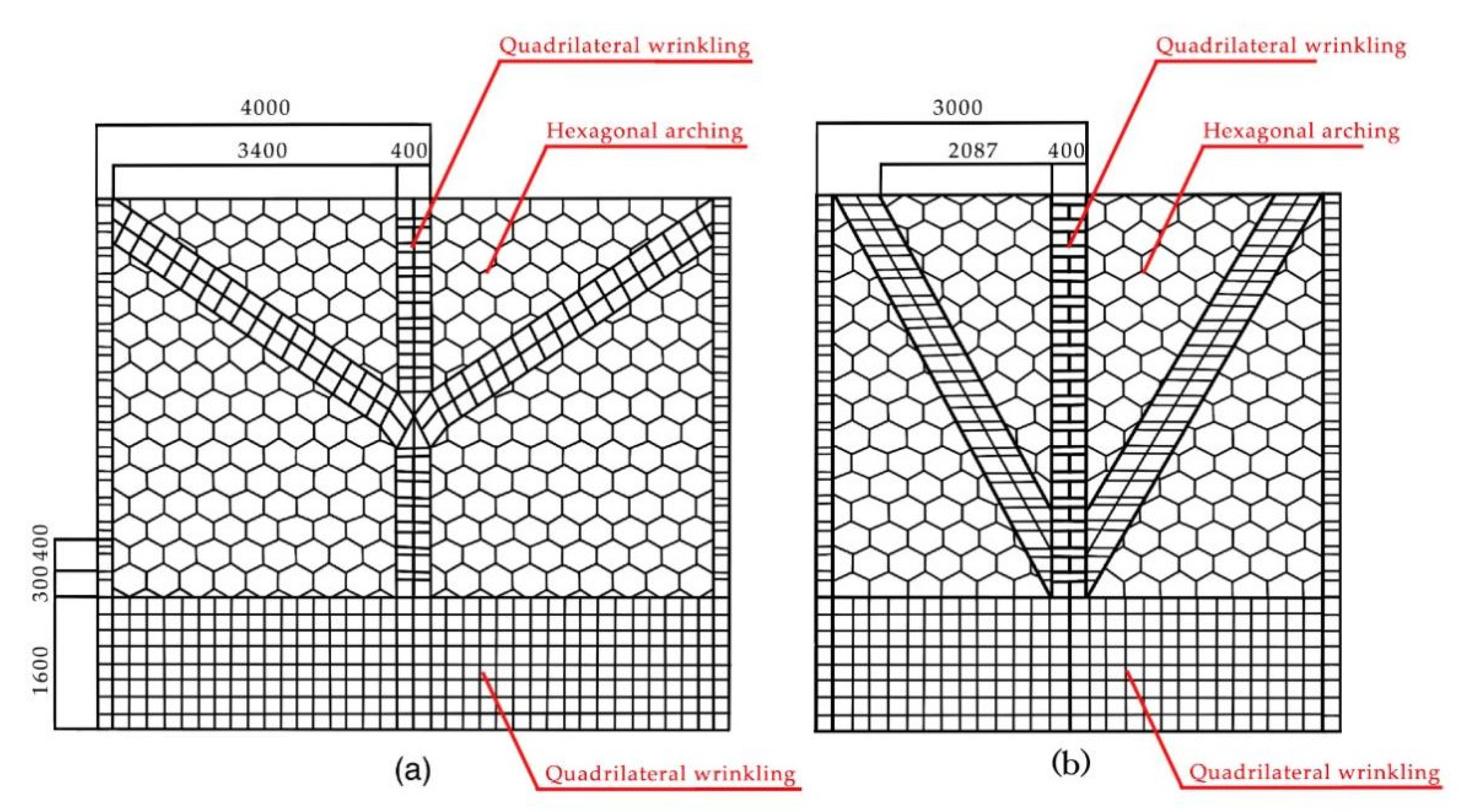
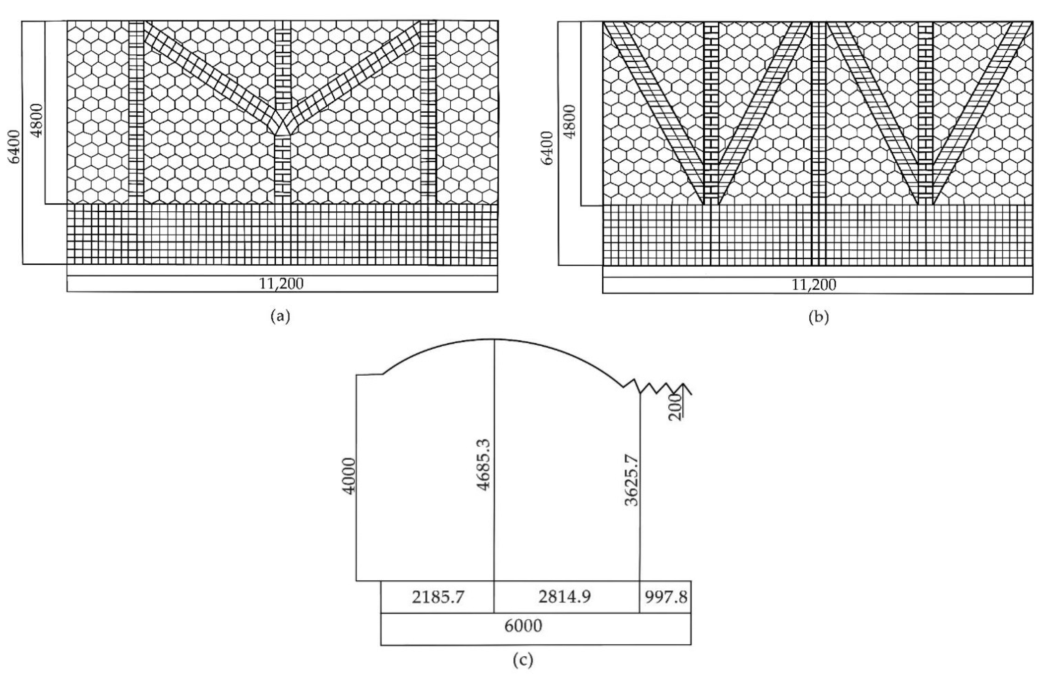
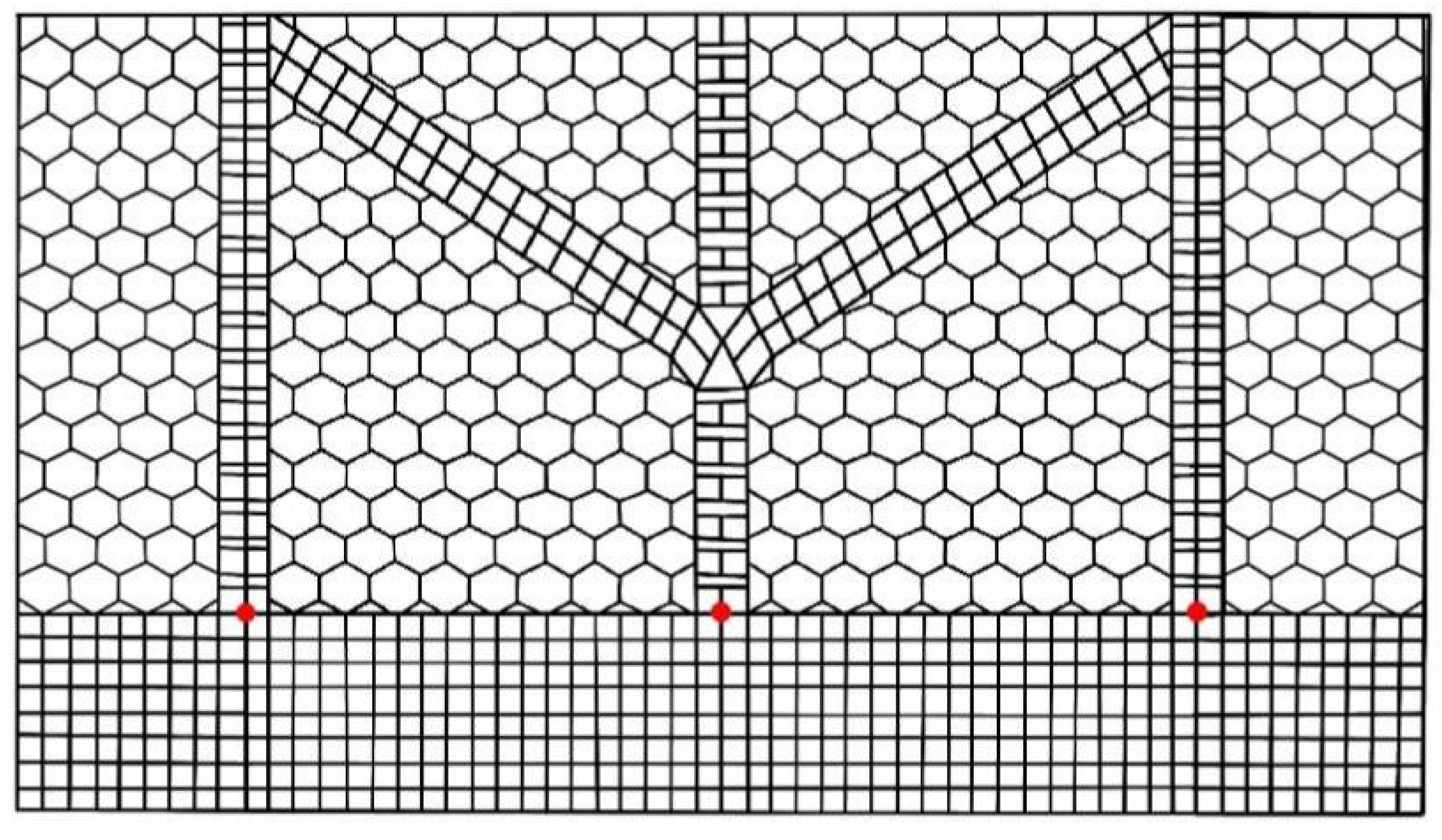
2.1.1. Modeling of Biomimetic Dragonfly Wing Mesh Structure

According to the observation of the actual dragonfly samples under the microscope, the dragonfly wings have a macroscopic lattice-like structure, and the basic geometry of the primary vein structure of the dragonfly wings is mostly quadrilateral and staggered quadrilateral cantilever lattices, while the secondary veins are mostly tri-, penta-, hexagonal and orthohexagonal cantilever lattices. Further observation of the main veins of dragonfly wings shows that dragonfly wing veins vary greatly in shape and size. Dragonfly wings have a three-dimensional structure, with the anterior and subanterior marginal veins being the thickest near the wing root and then decreasing toward the wing tip. Dragonfly wings are able to withstand the bending loads generated during flight because of the unique lattice structure of dragonflies. The ability of dragonfly wings to withstand bending loads during flight is due to the unique grid structure of dragonflies. The main veins of dragonfly wings are mostly a quadrilateral grid, the secondary veins are mostly pentagonal and hexagonal and the dragonfly wings are a three-dimensional structure with arches and wrinkles, where the wrinkle at the wing root is gradually flattened along the wing tip direction and with an arch structure at the wing tip. The dragonfly wing veins are covered with this ultra-thin transparent film which has a three-layer microstructure, with the central layer usually thicker than the covering layer and the two covering layers having almost the same thickness, which can further enhance the stability of the dragonfly wing veins, as shown in Figure 1.
We previously modeled a dragonfly wing sample to analyze its stiffness and concluded that both the main and full veins deform as a whole under different loads and concentrated forces, and the concentrated forces at the mesh tip will transfer the force from the wing tip to the wing root, fully reflecting the superior coordination of dragonfly wings, and the main vein, as the main frame of the wings, with greater stability. Through microscopic observation, the main veins of the dragonfly wings are quadrilateral and combined quadrilateral cantilever meshes, which are analyzed by finite element modeling to show that the quadrilateral mesh is stiffer than the staggered quadrilateral mesh under different uniform loads. Based on the three-dimensional structure of dragonfly wings, the main veins are puckered in three dimensions, and the quadrilateral and staggered quadrilateral meshes are derived with the help of finite element software to increase further with the height of puckering. According to the characteristics of the dragonfly wing vein covered film, the stiffness of the quadrilateral and staggered quadrilateral grids with increased film fabric was calculated, and it was concluded that the stiffness of the quadrilateral grid with film wrinkles was always greater than that of the staggered quadrilateral grid with film surroundings. Based on the hexagonal and combined hexagonal meshes obtained from the secondary vein observation for finite element software modeling, the hexagonal and combined hexagonal meshes are established according to the three-dimensional arching structure of the secondary vein of dragonfly wings, and it can be concluded that the stiffness of the membranous hexagon and combined hexagon increases with the increase of the sagittal-to-span ratio in the arching state, and the overall decrease of the mesh displacement and deformation under the tension of the membrane fabric.
According to the known experimental data and the principle of the dragonfly wing grid, we designed two kinds of carport floor plans based on the three-dimensional structure of the dragonfly grid, as shown in Figure 2. Based on the principle that the main wing veins of dragonflies are the main load-bearing structures, and that triangles have stability, two types of roofs were designed. The positive quadrilateral grid is the main bearing unit of the carport plan, with two branches connecting the middle bearing structure, a triangular grid form to reduce the bending angle of the three main veins and a three-dimensional wrinkling of the quadrilateral grid to further increase the grid stiffness.
The numerical design of the vehicle charging carport roof structure based on the biomimetic grid pattern utilizes a 200 mm side length for the quadrilateral grid and a 400 mm diameter for the hexagonal grid, as shown in Figure 2a. The carport adopts the quadrilateral grid, which produces wrinkles on the surface. Three main support structures form a triangle to divide the roof into two equal parts, with the central axis providing the arching effect and distributing the load evenly to both sides of the carport. Figure 2b shows the carport plan divided into four triangles, which make reasonable use of the stability principle of triangles. The carport diverges from the central axis to both ends, effectively distributing the load of the carport. Compared to carport II, carport I disperses the load from the arching point of the central axis to both ends. In carport II, the three main load-bearing axes at the wrinkling point divide the carport into larger triangles of equal size. Both carport grid designs are based on the stability principle of triangles and reference the actual carport frame structure.

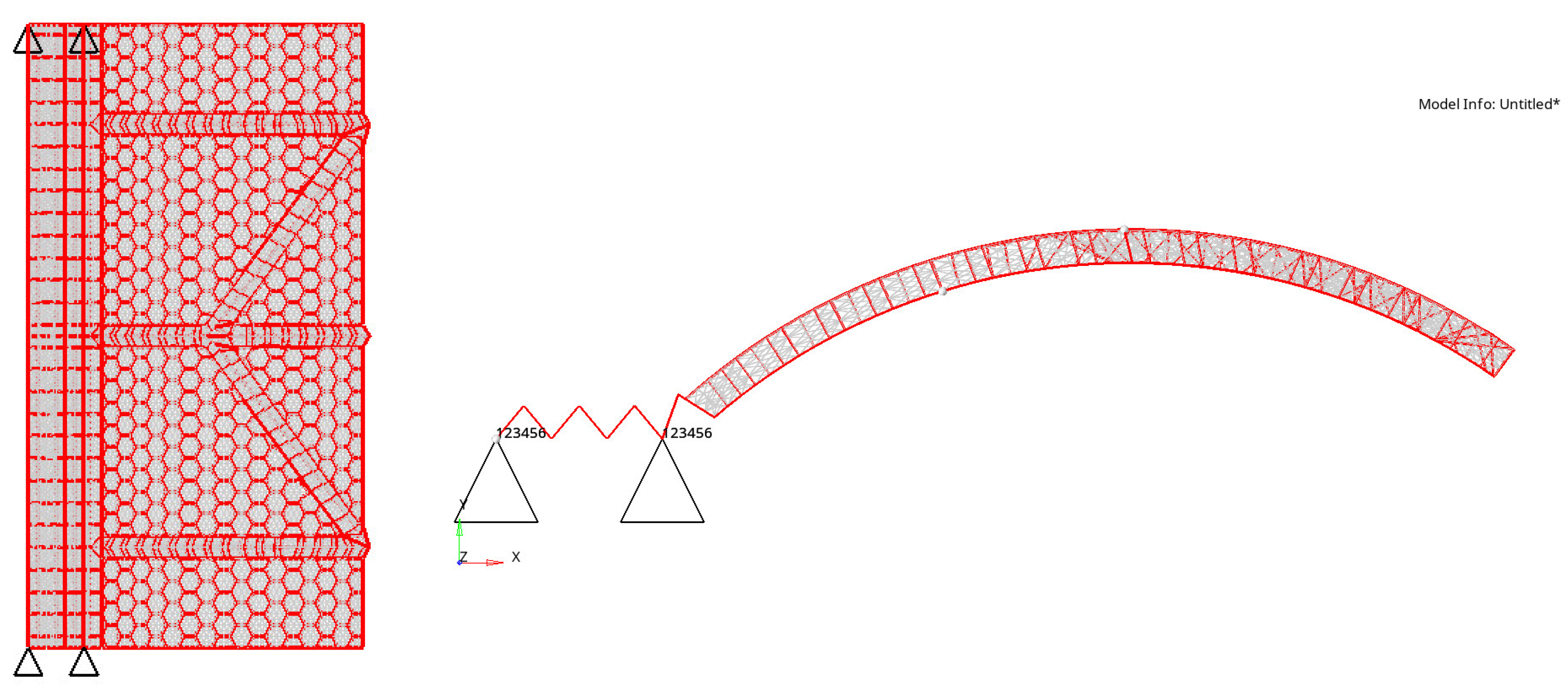
2.1.2. Establishing the Foundation Model of New Energy Vehicle Charging Post Carport

In the dragonfly wing structure, the grid shape size as well as the wing film thickness are not uniform. In the bionic design of new energy vehicle charging pile canopy, ignoring the factors that have little influence on the overall mechanical structure, and starting from the experimental principle of quadrilateral grid wrinkling and hexagonal grid arching, two new car charging pile carport 3D models are studied and established according to the two forms that have been designed above. In the modeling process, two models use a bar unit rod and a beam structure, with the Carport One model having a 1D size of 200 mm, where the number of units is 5461. The membrane cloth uses a two-dimensional shell unit simulation canvas plane structure with a shell unit basic size of 100 mm, and the number of units is 18,560. The Carport Two model size remains the same as Carport One, where the number of units of the beam structure is 5632 and the number of membrane cloth shell units is 18,731.
The shed of the membrane carport is mainly composed of membrane material, steel material, a steel cable, an anchor head and a pillar. In this study, a 220 mm I-beam is selected as the support column of the carport of the new energy vehicle charging pile, and the internal galvanized round pipe is used to weld the roof with the carport frame of the shed, with a size of 50 × 50 mm, a working load of F = 1000 N/m2 and a maximum working height of 4.685 m. The height of the pillar of the bionic new energy vehicle charging post is 3626 mm and the roof structure is in the arching style. In order to simulate the load under the self-weight case of the carport, prestress is applied to the carport model and the load is considered to be applied under stress stiffening to observe the magnitude of the stiffness and the deflection values of the two models. Furthermore, take the larger uniform load F = 1000 N/m2 and consider the effect of wind load, snow load and permanent load on the new energy vehicle charging pile carport. The model ignores nonmajor bearing force components and simplifies small structures such as rounded corners and chamfers to improve the calculation efficiency and accuracy according to the characteristic of the OptiStruct finite element software model that “the more concise the values, the more accurate the results”. In the establishment of the new energy vehicle charging pile carport model, tetrahedral cells are used in the HyperMesh finite element software to complete the carport mesh model, and its simulation model parameters are set in HyperWork. The skeleton components of the carport are welded by steel pipes and the steel pipe material parameters are selected from Q235 carbon steel, and the material parameters are shown in Table 1. The outer diameter of the skeleton structure is taken as 48.3 mm, the wall thickness is taken as 3.6 mm and the diameter of the steel pipe is 44.7 mm. Displacement constraints are applied to both ends of the structure located at six mesh lengths, and the finite element solution is completed by calling the file through the OptiStruct solver. In the first stage, finite element models of two structural forms were established based on the three-dimensional structure of the dragonfly wings, and the two models were designed for three limit state loads and three use limit state loads according to GB50009-2012 [28]. The support columns of the structure were compressed by the longitudinal load until buckling occurred, and the values were compared with the GB50017-2017 steel design standard for straight member support columns to determine the maximum buckling value of the support columns.
Most of the new energy vehicle charging post carports are membrane structures, which are architectural fabrics. The membrane structure is a kind of structure system which is composed of membrane material as the main tensioning body and a supporting structure. The membranes are made of polyester polyvinyl chloride (PVC) and glass fiber polytetrafluoroethylene (Teflon), which are about 200 times stronger than ordinary glass. UV-resistant materials have been added through a double-sided coextrusion process and can effectively block the UV protection of the car show’s paint and control the continuous heating of the car. Teflon material has the advantages of high strength, a high elastic modulus, being self-cleaning and having good durable fire resistance, so this carport adopts a polytetrafluoroethylene (PTFE)-coated glass fiber fabric, and the membrane fabric type selects a reverse-tension membrane structure; the membrane fabric parameters are shown in Table 2 and the thickness of the membrane fabric is taken as 2 mm.
The double carport conventional size is 5000 (L) × 6000 (D) × 2100 (H) mm/5500 (L) × 5500 (D) × 2100 (H) mm with a vehicle spacing of not less than 4800 mm, so the design of double carport, as shown in Figure 3, for the two model sizes is 11,200 (L) × 6600 (W) × 3626 (H) mm. Moreover, according to the actual design of the carport, the hexagonal grid with a sagittal-to-span ratio of 1/6 is chosen for the overall arching, the wrinkle height is 200 mm, the carport skeleton size is taken as 50 × 50 mm, the membrane fabric is taken as 2 mm, the displacement constraint is applied along the length of four grids on the left and right of the structure and the uniform load is F = 1000 N/m2. The quadrilateral wrinkling and hexagonal overall arching under load can transfer the force of the load to the fixed end of the carport to reduce the load of the carport, and the V-shape formed by the wrinkling can be used as a natural drainage channel under rain and snow to further reduce the pressure of the carport.
According to the actual static conditions, displacement constraints were applied to four locations in the finite element carport model. The constraints limited the displacement of the nodes on the model boundary, located at the four corners of the carport’s load-bearing wrinkling part, while the overall load of the carport was downward. As shown in Figure 4, the boundary nodes remained fixed, with fixed constraints on the X/Y/Z translational and rotational degrees of freedom, while the self-weight load trended downward.

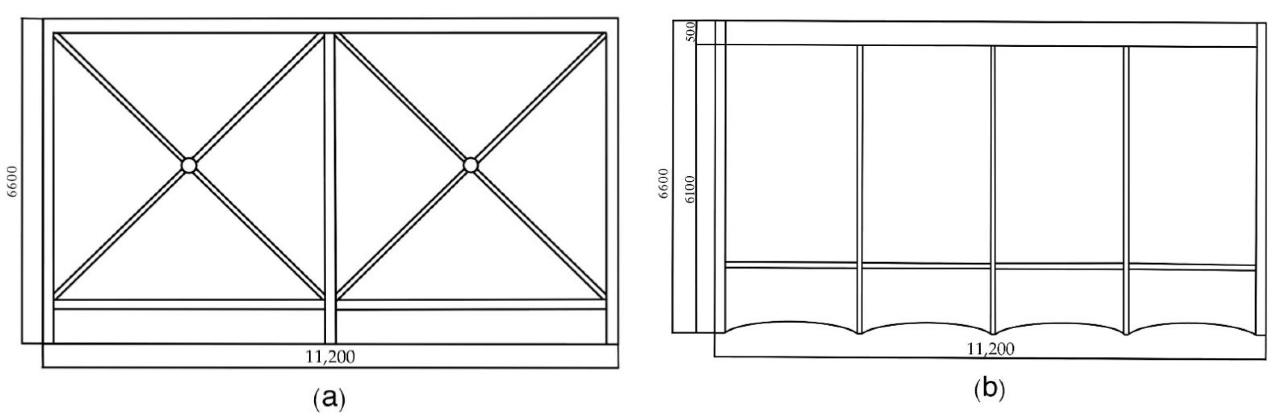
2.1.3. Existing Carport Modeling

Our research team conducted a survey on common new energy charging station shelters and found that existing membrane structure shelters can be roughly divided into two types: flat-top and hat-top membrane structure shelters. The flat-top shelter has a hard edge at the rear, tilts forward and is fixed with cables, with a significant height difference for drainage. On the other hand, the hat-top shelter has a dome shape, similar to a hat, and has no grid or other support structure, but is supported by a steel structure and covered with the membrane material.
To investigate whether the stiffness of the bionic dragonfly wing shelter is further improved, we have drawn the floor plan of the two types of shelters according to the results of field survey measurements, as shown in Figure 5, and established a finite element model. To compare the results as accurately as possible, the dimensions of the flat-top and hat-top shelters are the same as those of the bionic shelter model. The model uses 220 mm I-beam steel as the shelter pillar, 50 × 50 mm steel as the internal roof structure and Q235 steel as the steel pipe material. We plan to observe the displacement values of the flat-top, hat-top and bionic shelters under three different extreme loads to determine whether the bionic wing shelter further improves the stiffness of the shelter.

2.1.4. New Energy Vehicle Charging Post Carport Material Characteristics

In the analysis of the material characteristics of the carport of the new energy vehicle charging pile, the study focuses on the two important materials of steel and film fabric for the carport, and, according to the above material characteristics, the study establishes the relevant finite element model and numerical design experiments to obtain more realistic data and comparisons.
First, the steel used in the membrane carport. The steel used in membrane carport is required to have strong tensile strength, elongation and yield strength, while its own sulfur, phosphorus and carbon content of qualified assurance, cold-bending-test-qualified assurance, welding rod, wire, flux and other yield strength, elongation, ultimate strength and impact toughness, etc., need to be matched with the main metal. Jia Suizi used a single row of reinforcement to produce a lightweight recycled concrete wall precast structure, allowing the lightweight steel frame restraint to significantly reduce the damageability of the walls and improve the ductility and energy efficiency of the structure [29]. Roberto Tartaglia designed an industrial steel building to further enhance the seismic resistance of the building with full-vein structural modifications for seismic and wind effects [30]. Zhiyi Wang proposed an improved Gaussian transformation model to simulate and analyze the fire prevention and practical application of monolithic steel structures in complex spaces, and established a series of system integration methods [31]. Ali Tighnavard Balasbaneh used LCA and LCC methods to compare the life cycles of steel and concrete, and the results showed that steel exhibits better performance in all aspects due to the recovery, recycling and reuse of materials at a lower cost [32].
According to the public carport facilities with steel, mainly to meet the requirements of the current national standard of GB700-2006 “Carbon Structural Steel”, the Q235 steel with good weldability, good plasticity and toughness is selected as the framework material for the exposed environment, and for the special requirements of corrosion resistance or the load-bearing structure, the weatherproof structural steel should be used. Its performance and technical conditions should be in line with the national current standard of “Weatherproof structural steel” GB/T4171 of the provisions. All steel tubes are made of international welded tubes, where the measured value of the steel tensile-strength and yield-strength measured ratio is not less than 1.2, the yield point is not more than 10% of the standard value and the elongation is more than 20%, with a good yield step and good weldability. The Q235 steel is selected as the skeleton of the carport, and the density is taken as 7.85 g/cm3, while the elastic modulus is 210 Gpa and the Poisson’s ratio 0.25 v. The load-bearing steel is 10 cm × 10 cm square tube and the steel size of the structural beam of the roof is 5 cm × 5 cm square tube.
Second, the membrane structure of the carport membrane fabric. New energy car charging pile carport membrane cloth should have an extremely high tensile strength as well as a good self-cleaning function, with a life span of not less than 15 years, in line with GB requirements. He Y used a cable–membrane contact model to analyze the wind-driven response of air-supported membrane structures with orthogonal cable networks to further optimize the design of large-span air-supported membrane structures [33]. In order to mitigate the environmental radiation cooling, Wang J used a high-strength flexible membrane with a reasonable pore structure as a selective radiator [34]. In order to determine the typical and basic thermal characteristics of the membrane structures, Tian Guo ji summarized the research on the indoor thermal environment of the membrane buildings and made some reasonable suggestions for the future indoor thermal environment of the membrane buildings [35].
Compared with traditional sunlight panels and color steel plates, membrane carports have stronger rigidity, higher economy and shorter span, and lighter weight, which can significantly reduce the pressure of the carport skeleton. In this study, the superstructure of the new energy vehicle charging post carport is a steel truss structure plus a cable membrane structure, while the PTFE membrane is a composite membrane material composed of glass fiber base fabric plus the PTFE coating, which has extremely high strength and is durable and fireproof. Therefore, this carport adopts the domestic PTFE coated glass fiber membrane, using the compound C grade standard, with a membrane tensile degree standard of not less than 1900 N/cm3 in the radial direction and not more than 3100 N/cm3 in the weft direction. The PTFE membrane material, whose flame retardancy meets the national GB8624-97 test, is a flame retardant B1 grade, with no fire drops, no toxic gas, a temperature resistance in the range of −40–120 °C and which will not cause deformation; the two new energy car charging pile carport models therefore use the same material properties to ensure a more accurate stiffness comparison.

2.2. Experimental Simulation Method and Detail Setting

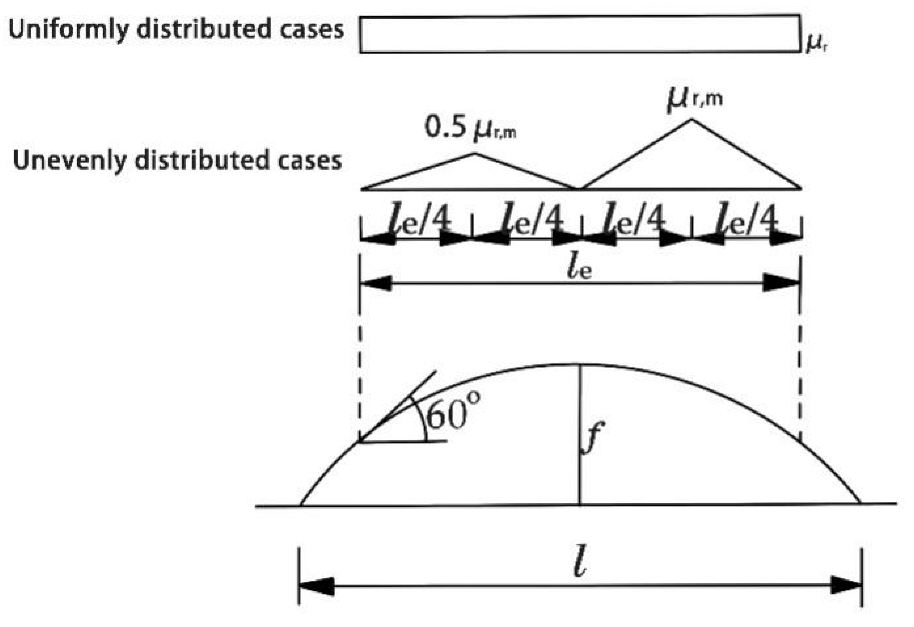
2.2.1. Load Experimental Analysis Method

The design of the building structure should be based on the load that may appear on the structure at the same time during use, and the load combination should be carried out according to the limit state of the bearing capacity and the limit state of normal use, respectively. Many scholars also carry out the test analysis under different loads for different buildings. Zhang X designed a zero-energy house which tested the house performance and load flexibility, and revealed the dependence of the load flexibility on the overall heat loss performance of the building [36]. Eva Lucas Segarra investigated a method to calculate probabilistic loads to predict future building energy performance [37]. Jin qiang Xu used the RNG model to simulate the wind loads of traffic road signs at different wind speeds in order to improve the wind resistance of traffic signs, and finally found that an appropriate hole diameter and hole spacing could reduce the wind loads of road signs [38]. Dong-Jin Cheon conducted wind load tests on a dome with a central opening to prevent wind damage to the open retractable roof of the membrane dome cladding [39]. Nathalie Domede compared lighthouse design methods of the last century with current European standards, and the strength of masonry under wind loads during the experiment prompted further study [40]. Ceyhun Aksoylu studied damage to the end zone of the precast purlins due to a roof snow load and proposed a new type of reinforcement with a “Z” specimen that has a bearing capacity of approximately 30% higher than other specimens [41]. Vuk S. Milošević performed load tests on stretched membranes as well as prestress tests to reveal whether the point load deflection produced significant membrane deflection [42]. The structural design of the new energy vehicle charging pile carport should consider the stiffness and stability of the carport as well as the displacement distance, thereby requiring that the deformation and stiffness of each structure under permanent load and other special load cases shall not exceed the range permitted by the carport; therefore, according to the load standard of carport structural design “Code of Construction Load” GB50009-2012, the load borne by the new energy vehicle charging pile carport is divided into the permanent load, live load, wind load and snow load.
The permanent load includes the self-weight of structural construction, fixed equipment, long-term storage, etc. The standard value of the structural self-weight should be determined by the design size and material density calculation of the structural elements [43]. The local load generated by the industrial building during production use or installation and maintenance can be replaced by the equivalent uniform live load, and the combined value and frequency encounter value of the carport roof live load is not less than 0.7. The parameters of the carport roof uniform live load are shown in Table 3. The carport roof uniform live load, whose standard value should be between 0.5 and 0.7 kN/m2 due to the live load vertical force, can take the larger value for calculation; however, the uniform load cannot be calculated with the snow load repeated combination. The local load generated by the industrial building during production use or installation and maintenance can be replaced by the equivalent uniform live load, and the combined value and frequency encounter value of the carport roof live load is not less than 0.7. The parameters of the carport roof uniform live load are shown in Table 3.
The greatest value of the live load QL is taken as 0.7 kN/m2 for the calculation. The membrane carport is designed to withstand 0.5 kL of live load on the horizontal projection surface of the carport according to the load standard for all carport members. The wind load is the pressure exerted by air flow on an engineering structure, the magnitude of which is proportional to the square of the wind speed [44]. The standard values of wind loads are the average wind pressure plus the equivalent wind pressure caused by pulsating wind, resulting in the wind vibration of the structure, and the average wind pressure multiplied by the wind vibration coefficient βz, respectively. The building structure is subject to wind loads related to the size, sea-level height and wind speed and direction, where the standard value of wind load acting vertically on the unit area of the building surface is wk (kN/m2), calculated as follows:
wk = βzμsμzWo
where wk is the standard value of wind load, βz is the wind vibration coefficient at height z, μs is the wind load body type coefficient, μz is the wind pressure height variation coefficient and Wo is the basic wind pressure (kN/m2).
The carport structure is generally a nonhighrise structure building, and in the calculation of the wind vibration coefficient, takes the value of 1.0; with the reference arch carport shed roof structure, the body coefficient takes the value of 0.6; the wind pressure according to the carport model height takes the value of 0.6; the basic wind pressure according to the national strongest wind pressure of 50 years takes the value of 0.65 kN/m2.
Snow load refers to the snow load acting on the roof of a building or a structure, which is a spontaneous meteorological load. The standard value of the snow load on the horizontal projection of the roof should be the product of the snow distribution coefficient of the roof area and the basic snow pressure. The formula is:
sk = μrso
where sk is the snow load standard value (kN/m2, μr is snow distribution coefficient on the roof and so is the basic snow pressure (kN/m2).
μr = l/(8f) (0.4 ⩽ μr ⩽ 1.0); μr,m = 0.2 + 10f/lr,m ⩽ 2.0)
According to the actual single-span arch roof, the maximum value of roof snow is 1.0; the basic snow pressure is taken as the average value of the maximum snow accumulation in Nanchang City over 50 years, and the self-weight value is taken as 0.35 kN/m2. The snow distribution coefficient of the arch roof is shown in Figure 6.

2.2.2. Simulation Details

The study performs a load analysis on two models of new energy vehicle charging pile carports based on the dragonfly wing mesh structure simulation and analyzes and compares the following values.
a.
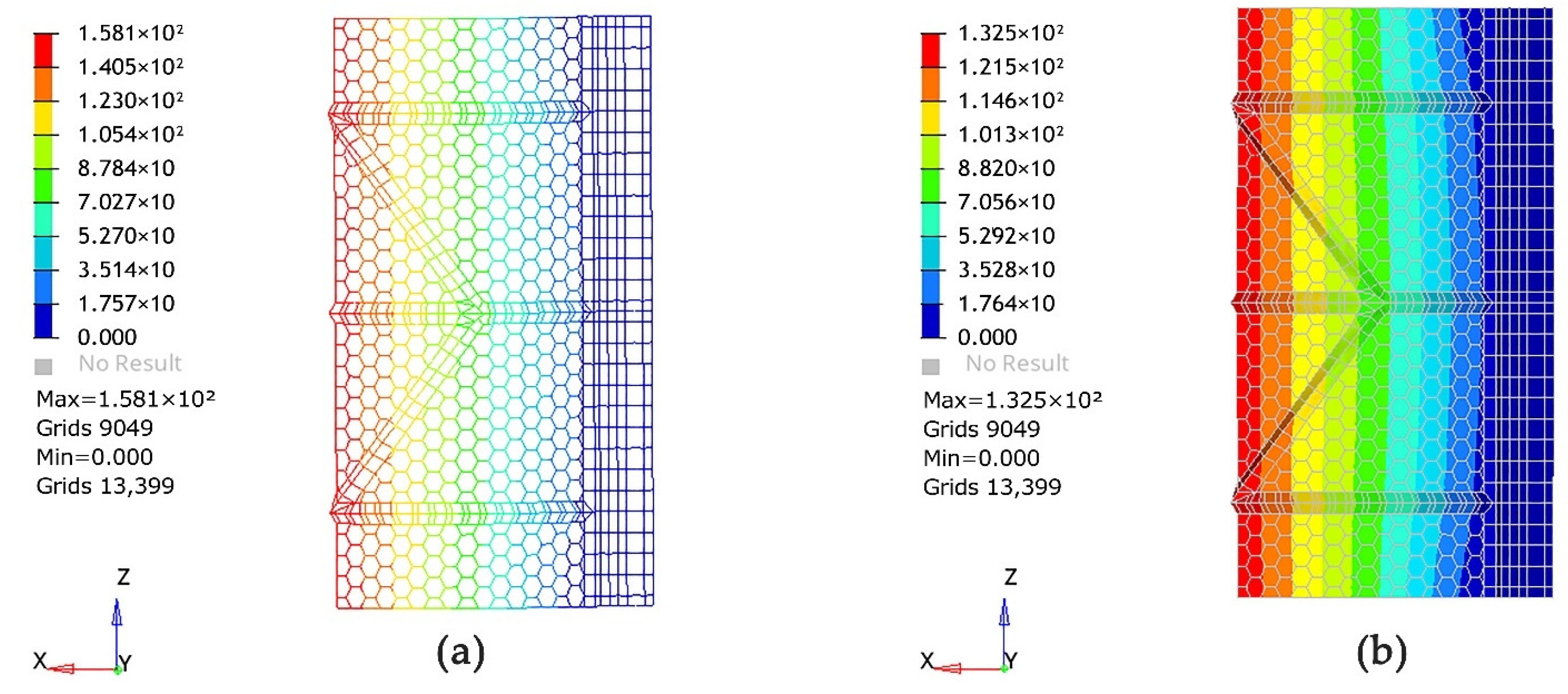
Comparison of maximum deflection under the dead weight of the two models under the same uniformly distributed load.
b.
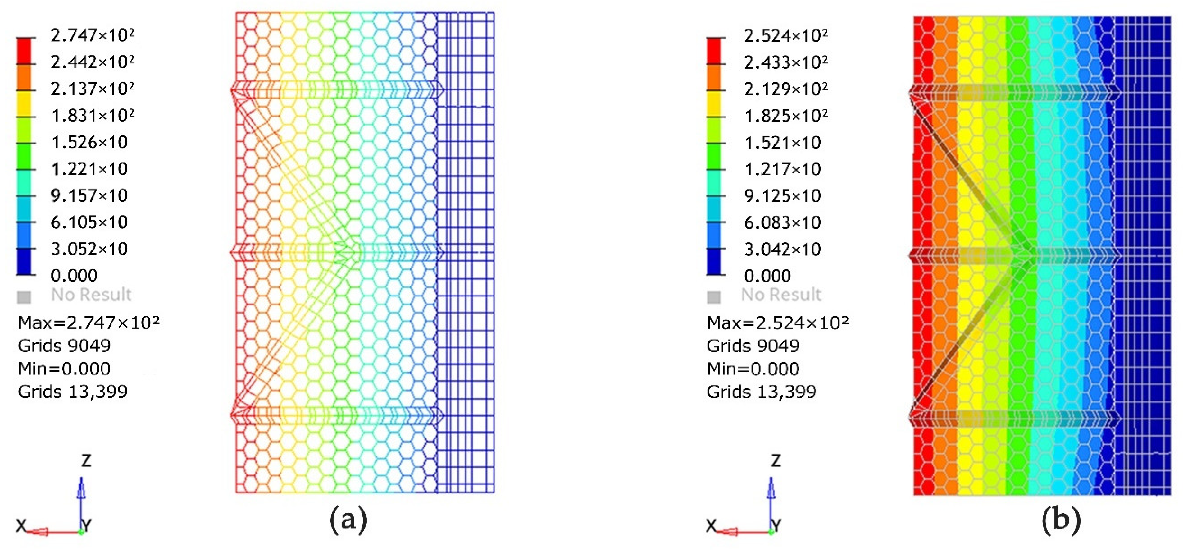
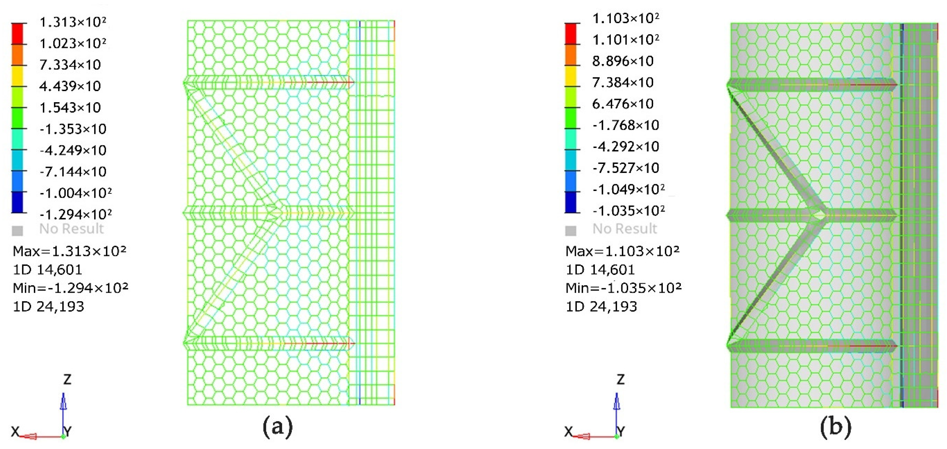
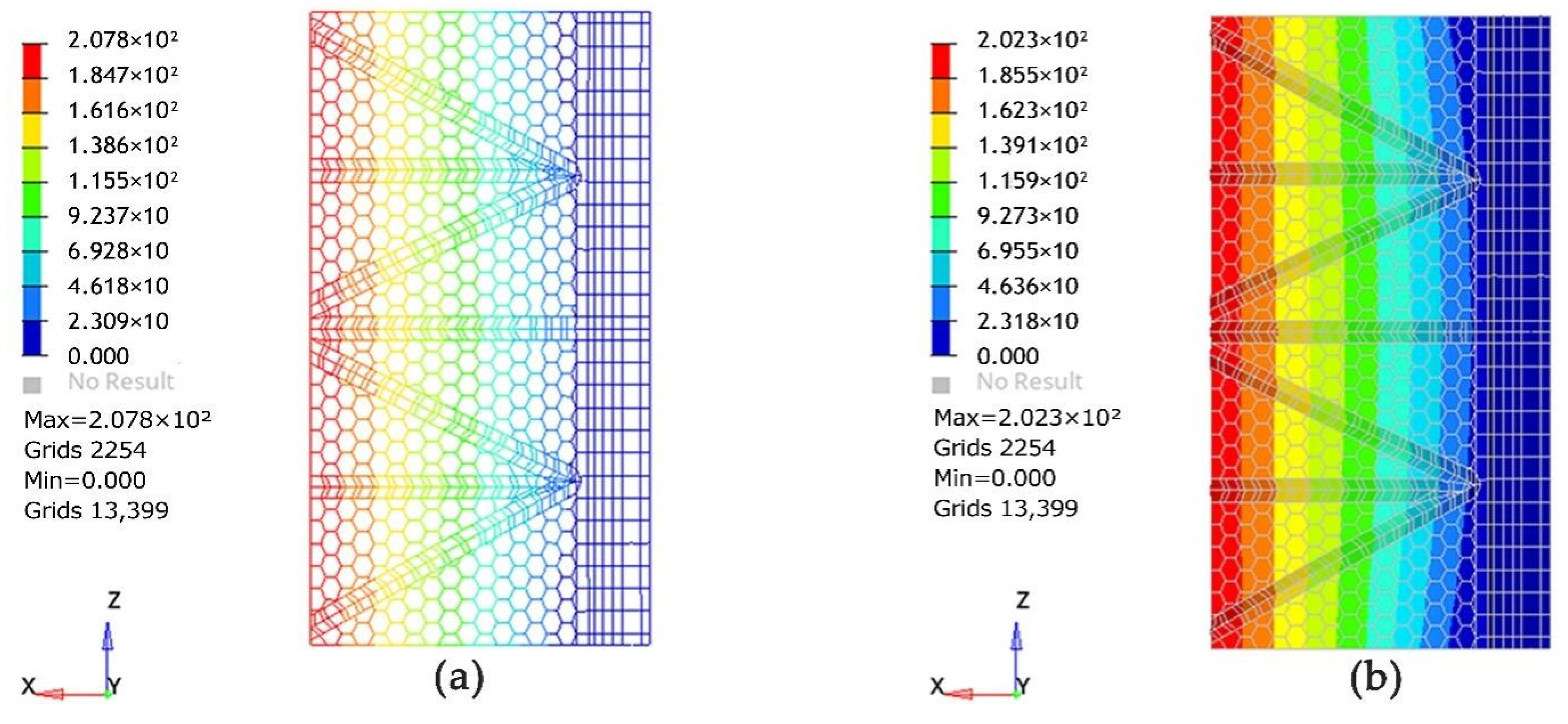
Comparison of tensile and compressive stresses under the dead weight and external uniformly distributed load.
c.
Comparison of the maximum deflection values of the skeleton and membrane cloth under the action of the dead weight.
d.
Comparison of the maximum deflection, tensile stress and compressive stress under the dead weight and external uniformly distributed load.
According to the influence of the outside natural wind and snow load on the carport, the mechanical analysis is based on the buckling value of the carport support column under different load conditions, and the main external force load and data of the carport with the support column, where the model load design values are as shown in Equation (1):
S = γ G S G k + ψ Q γ Q S Q k + ψ w γ w S w k
where S is the design value of the load combination of the carport; γG is the permanent load subfactor; γQ is the floor live load subfactor; γw is the subfactor of the wind load; SGk is the standard value of the permanent load effect; SQk is the standard value of the floor live load effect; Swk is the standard value of the wind load effect; ψQ and ψw are the coefficients of the combined value of the floor live load and the wind load, respectively, and when the permanent load effect plays a controlling role, it should be 0.85; when the variable load effect plays a controlling role, it should be 1.0.
The steel membrane structure canopy is not designed for floor activities. According to the formula for the load combination of the charging station canopy, and considering the actual situation of the canopy, we can determine that the significant loads that the canopy will face under natural conditions are wind load and snow load. Based on the “Code for Load of Building Structures” GB50009-2012, which is the load standard for structural design, we investigated the average values of natural condition loads in southern areas, including Nanchang and surrounding areas in Jiangxi, over a 50-year period. We summarized several combinations of natural working conditions in Table 4 to facilitate the determination of the canopy’s load and stiffness testing under different situations. We also calculated the extreme weather load occurring once in 50 years and added it to the load design to ensure the authenticity and effectiveness of the data simulation.
The study uses the solver OptiStruct for the finite element model analysis, using standard finite element cell-types for linear, nonlinear static and modal analysis, and the best model structure is selected by the numerical comparison of the stiffness of the tested carport models according to the different load cases.
In order to prove that the bionic design of the carport based on the dragonfly wings has better stability, we choose two typical carports for structural analysis and modeling according to the existing types of the membrane structure charging post carports in the market. Because the more concise the finite element software model, the more accurate the experimental data, in order to ensure the accuracy of the experimental results, we did not take into account any factors other than the structural material. The optimal carport structure was selected by analyzing the stiffness of the selected carport under different loads.

2.2.3. Expected Model Shed Roof Deformation

Based on the available software support and the existing research results, the prediction of the carport deformation by different directional forces is carried out. In this study, the new energy vehicle charging post carport is designed as a wrinkled steel structure vaulted roof, and the loading paths are preset for vertical and lateral loads according to the actual force environment of the carport. In order to resist the vertical load of the self-weight of the carport, the connection between the roof and the longitudinal column cannot support the overall structure of the roof, which will lead to the overturning moment of the peripheral beam of the roof; the overturning moment causes axial force, and the periphery of the roof is tilted without the support of the supporting column. The deformation of the roof under the vertical load is shown in Figure 7.
When the main axis surface is subjected to lateral load, the roof beam at the windward side is also subjected to lateral load deformation, and this load causes different overturning moments on the carport according to different orientations, as shown in Figure 8.

3. Results

The bionic dragonfly wing carport structure of the new energy vehicle charging post was set up for mechanical comparison under the same mechanical conditions, and the bionic carport model with the highest stiffness was selected for further analysis. The shed roof model is set up as a dragonfly wing bionic shed model with only a skeleton structure under a uniform load, a dragonfly wing bionic shed model with a skeleton plus a shell structure, a dragonfly wing bionic model with an additional pillar skeleton plus a shell structure and a dragonfly wing bionic model under different working loads.
The research results include three parts: firstly, the finite element modeling of the bionic carport with two wings under the uniform load as well as the ultimate load and the conventional load for mechanical comparison; secondly, we select the suitable thickness of the support columns and add struts to the bionic model to compare the stiffness of added struts and unadded struts under uniform load; finally, we compare the stiffness of added struts and unadded struts under different loads in the limit state to select the best form of carport model.

3.1. Mechanical Comparison of New Energy Vehicle Charging Post Carport Models

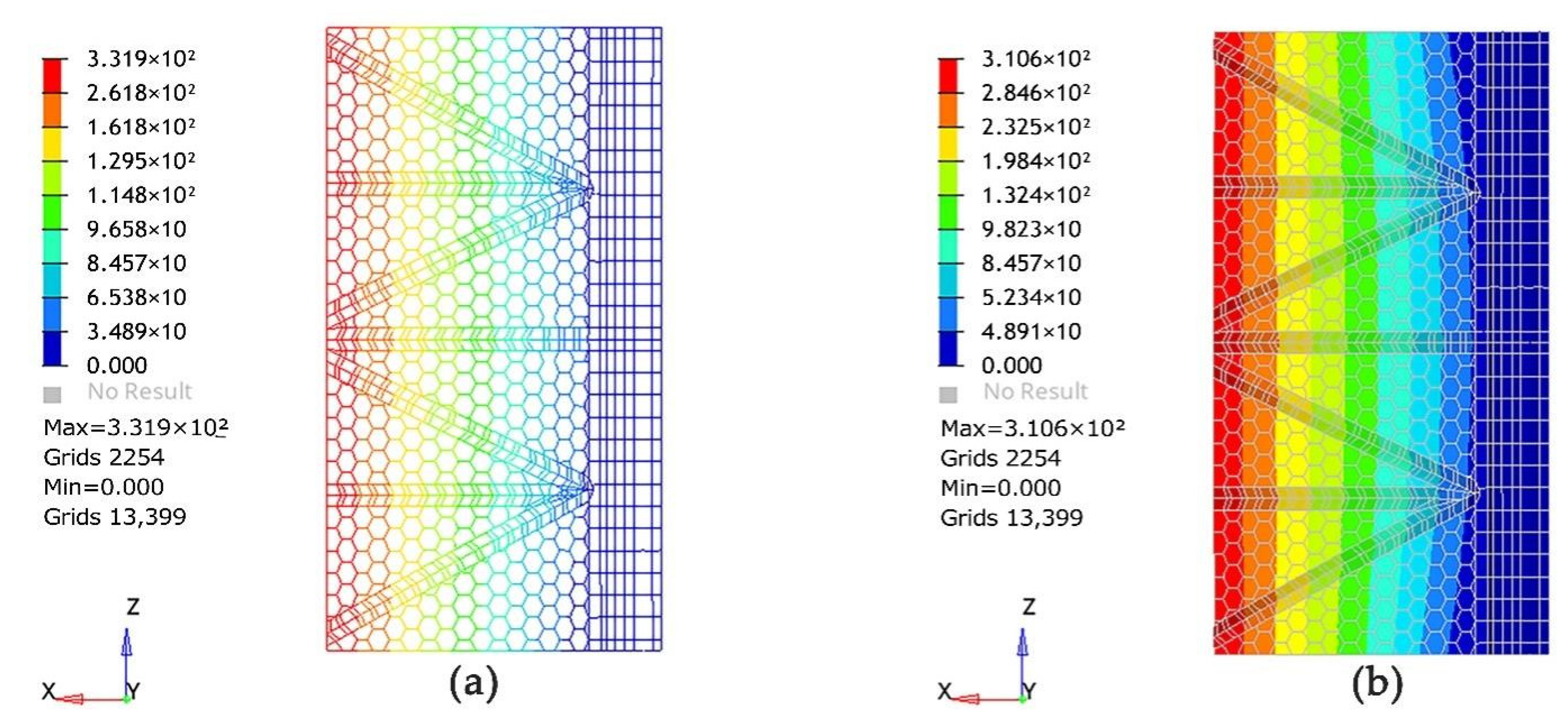
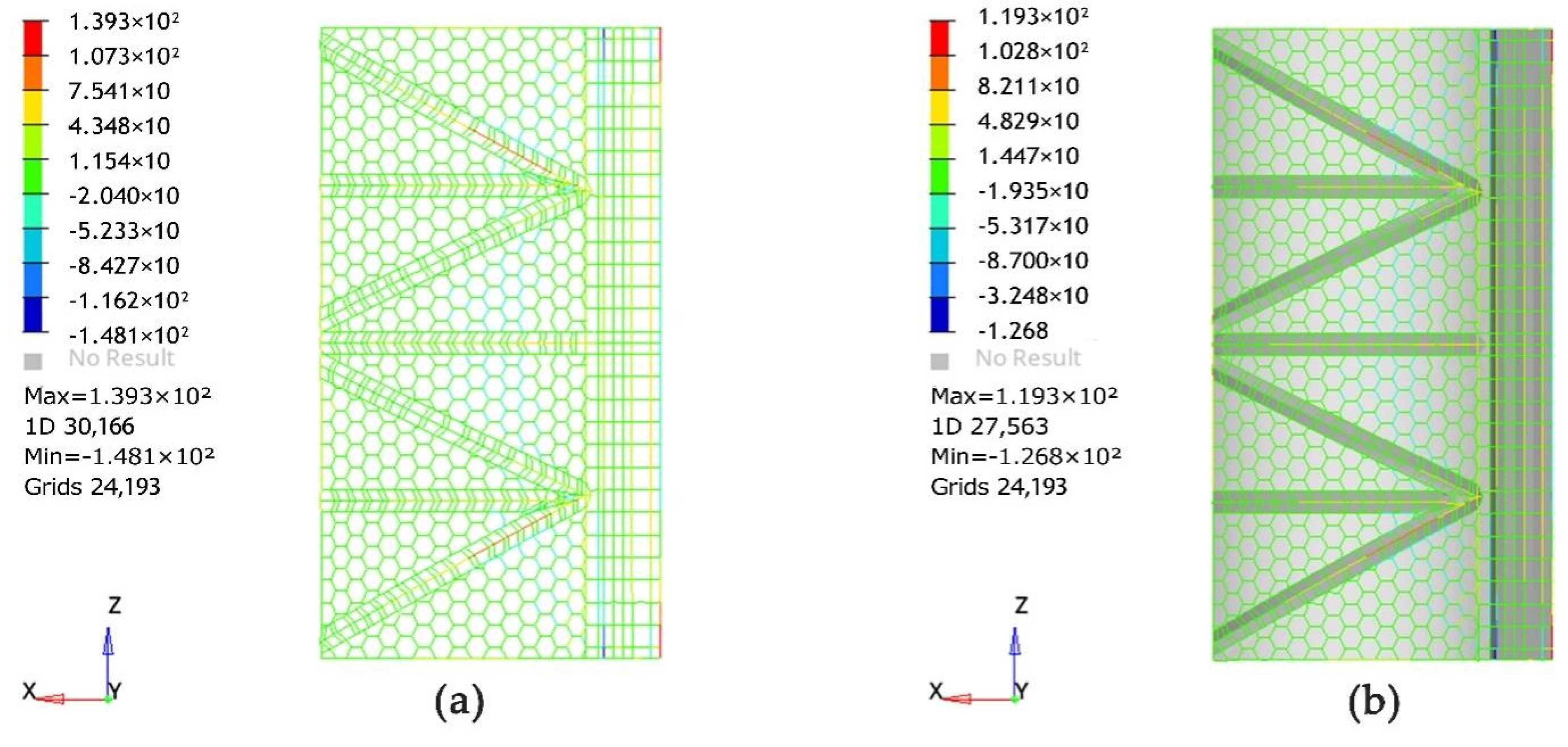
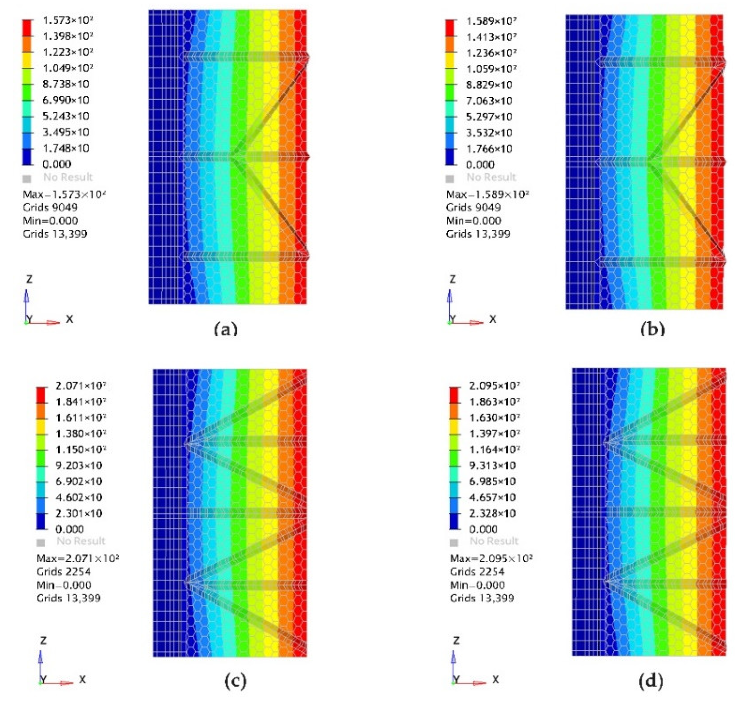
3.1.1. New Energy Vehicle Charging Post Carport Model I Mechanical Comparison

The structure of the dragonfly wing bionic carport model I was imported into the OptiStruct finite element software for modeling and mechanical simulation. To facilitate the comparison of the deformation of each structure of the two models, the two bionic carport models were subjected to displacement constraints on the left and right of the structures, and the effects of uncertain loads under natural conditions were considered, where a larger mean load of F = 1000 N/m2 was taken for the nonlinear static analysis. Figure 9 shows the numerical plot of the maximum deflection of model I under self-weight.
In order to make the research data more realistic and accurate, the external mean load was added to the bionic carport model to further observe the maximum deflection values of model one under a permanent load plus an external load. Figure 10 shows the maximum deflection of the bionic carport model I under the increased external load of F = 1000 N/m2.
The carport is subjected to an external load and the internal skeleton generates a reaction. Figure 11 shows the tensile and extrusion trend of the bionic carport model I under the action of self-weight plus an external load.

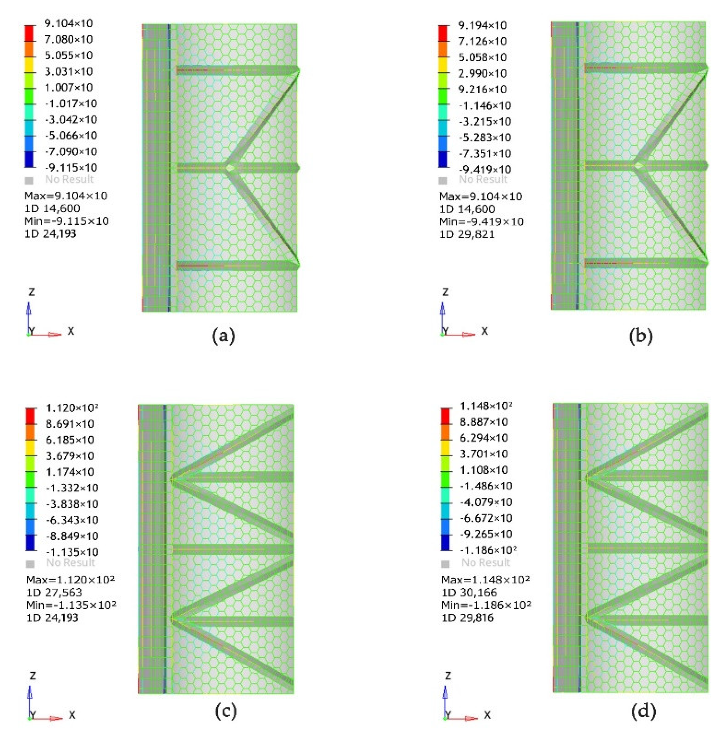
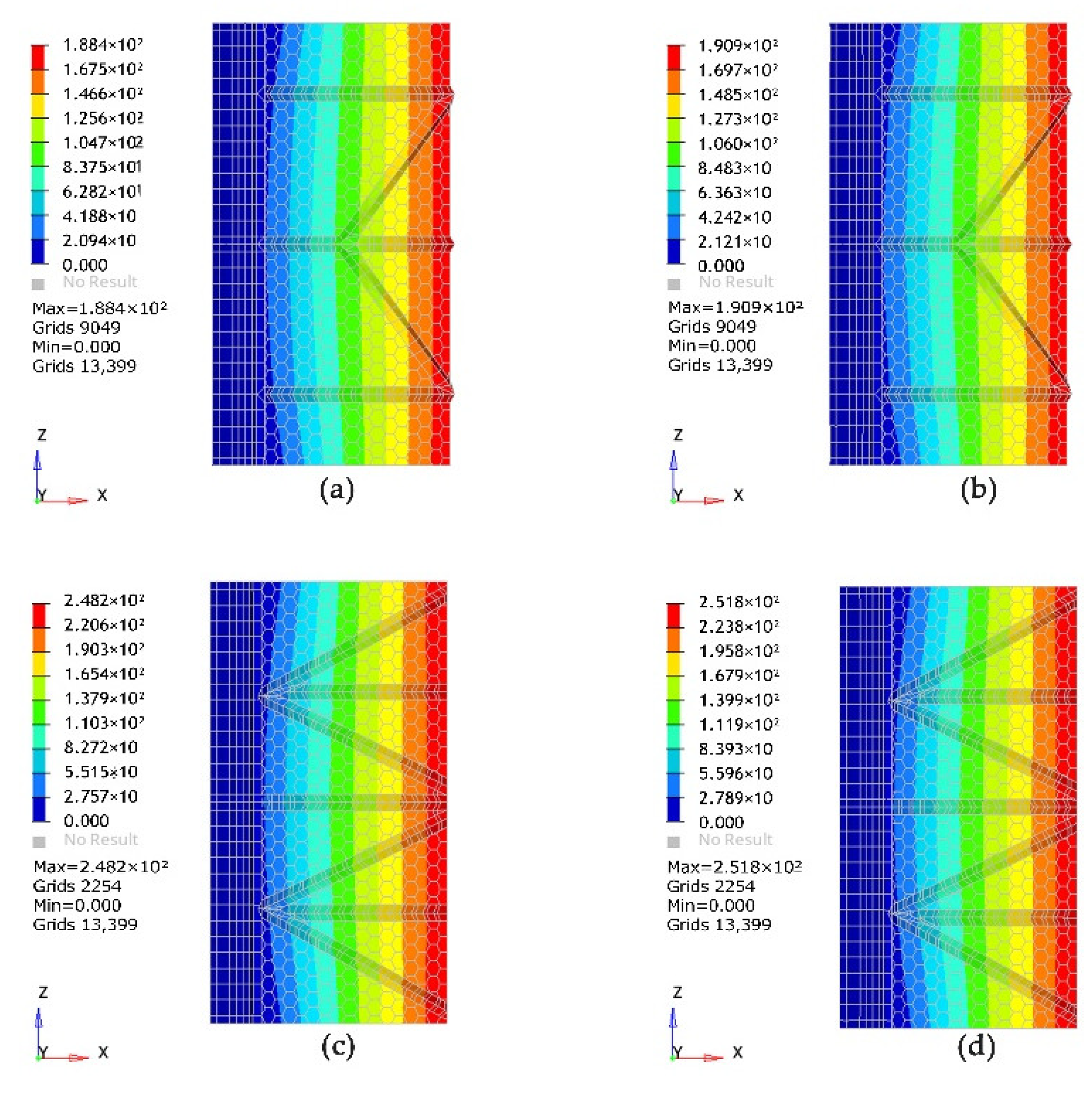
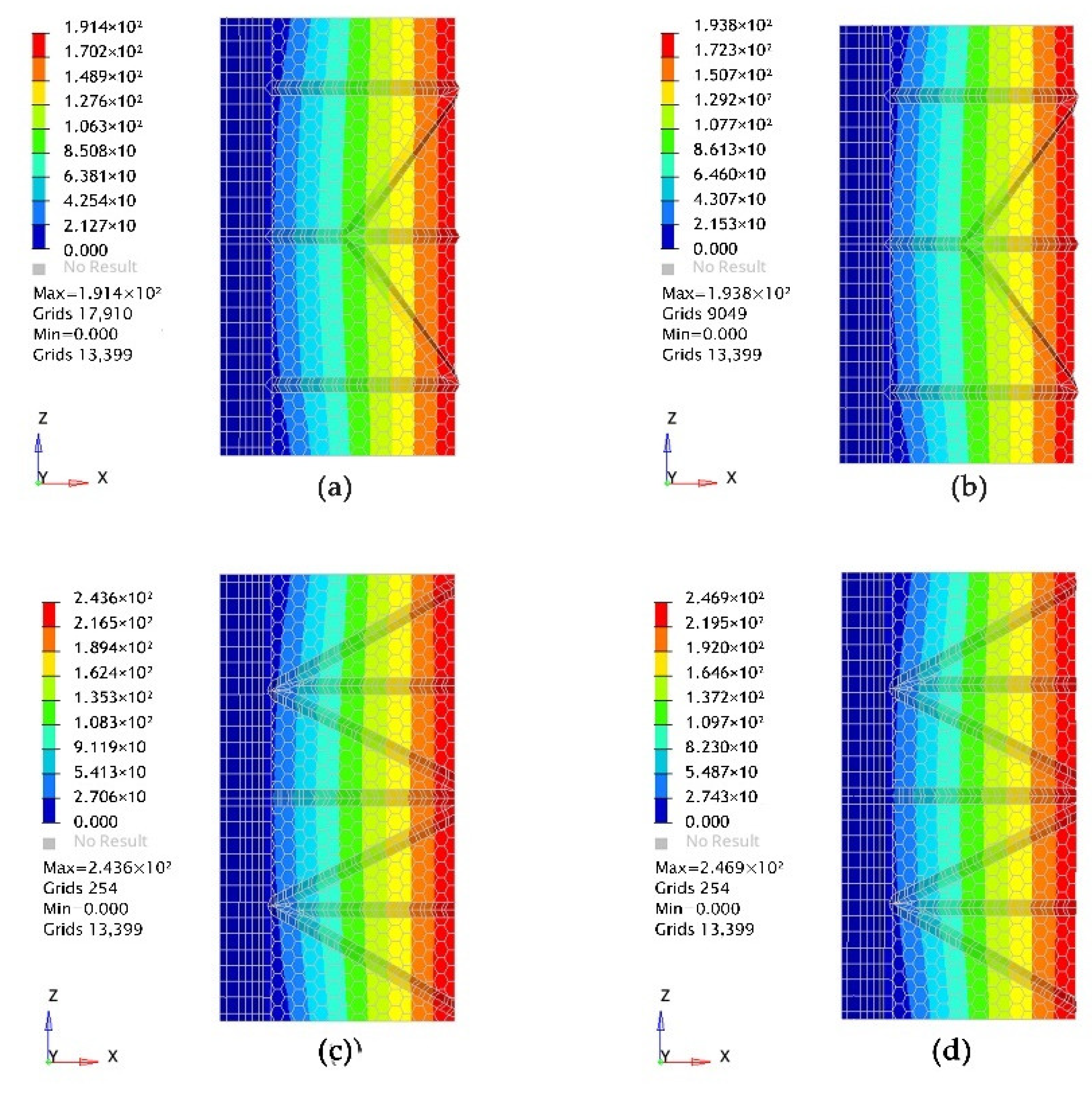
3.1.2. Mechanical Comparison of the New Energy Vehicle Charging Post Carport Model II

According to the bionic carport model II of the dragonfly wing structure, its maximum deflection values under self-weight are shown in Figure 12; the maximum deflection values under self-weight plus an external load are shown in Figure 13; the stress nephogram under self-weight plus an external load is shown in Figure 14.
In the design and manufacturing of a biomimetic carport, the stress-stiffening effect is one of the factors that must be considered. When conducting finite element analysis, it is important to simulate real-life situations as much as possible and to consider factors such as material and structural nonlinearity and the stress-stiffening effect to obtain more accurate simulation results. The stress-stiffening effect has a significant impact on the membrane structure of the biomimetic carport. To consider this effect, a “stress stiffening” matrix is generated as an auxiliary stiffness matrix through finite element software programs.
Table 5 shows the maximum deflection and stress values of model I and model II with and without considering the stress-stiffening effect under the self-weight and self-weight plus external load conditions.

3.2. Overall Performance Analysis of New Energy Vehicle Charging Post Carport Model

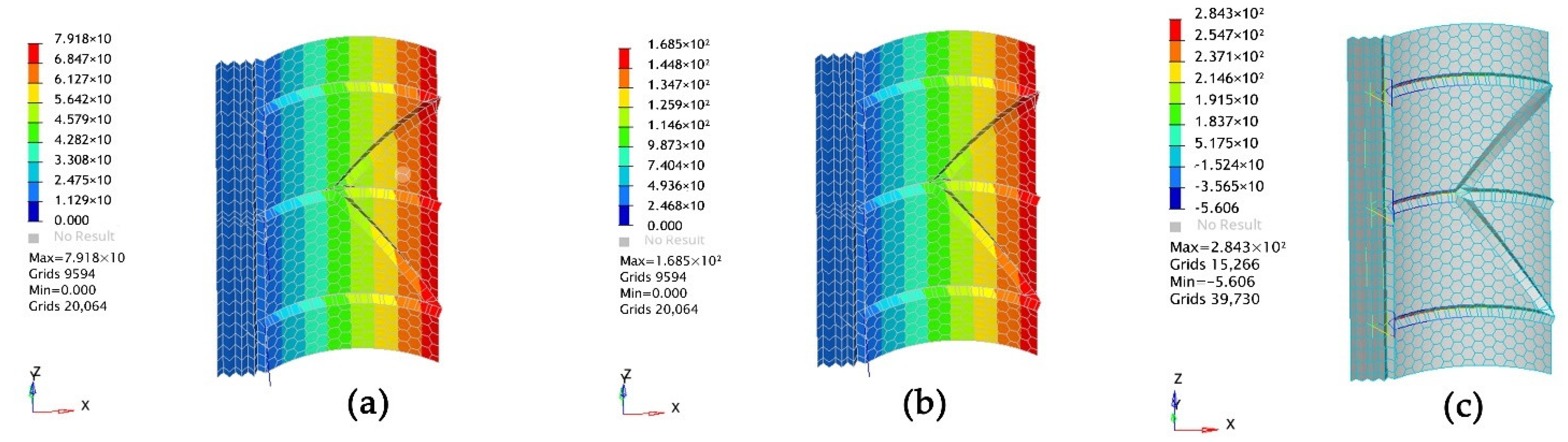
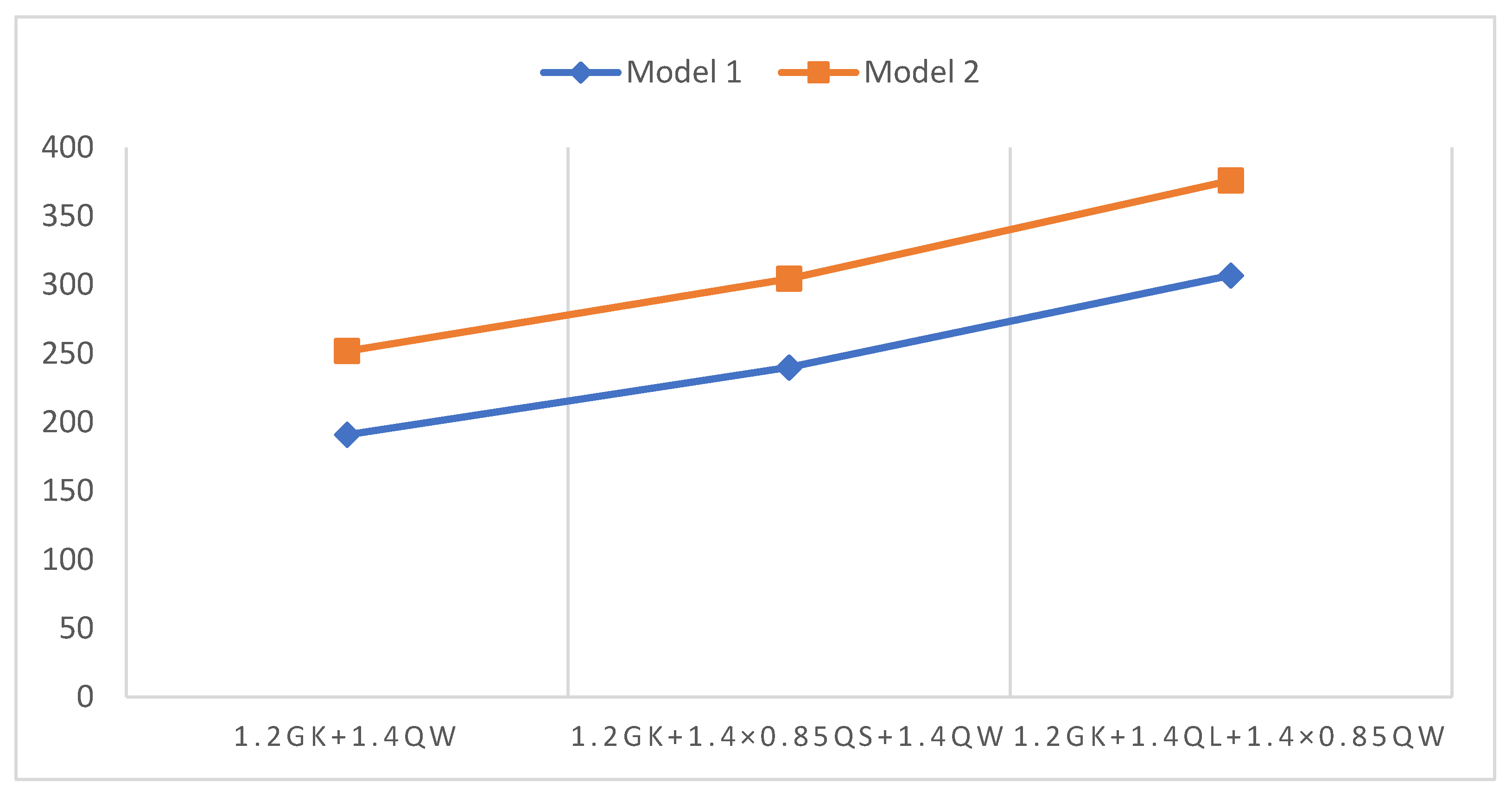
3.2.1. Analysis of the Overall Behavior of the Carport Model Structure in the Limit State

This section discusses the structural performance of the bionic carport model under unfavorable operating conditions. Stress analysis and maximum displacement analysis are the main factors to observe for whether the carport structure meets the index. The study analyzed the maximum stresses in carport I and carport II and the maximum displacement values in different axes using linear static and nonlinear static solvers. As the steel used in this steel membrane carport is Q235 steel, the yield stress of all steel members is 235 MPa, and ideally the deformation of the steel membrane structure of the carport under different working conditions does not exceed the specified value, and the displacement caused by the deformation of the steel structure is small. The ultimate load-carrying capacity of the carport structure was also compared, and the OptiStruct solver was used to test the maximum amount of load that the carport could withstand; when the structure reached a critical state where it could not withstand excessive loads, the load value could be recorded as the critical load.
Firstly, the structural performance analysis of the new energy vehicle charging pile shed under the load of 1.2 GK + 1.4 QW was carried out. As shown in Figure 15, the total stress of both carport I and carport II is 1.2 GK + 1.4 QW. Figure 16 shows the combined displacement of carport I and carport II under the 1.2 GK + 1.4 QW load.
Secondly, the structural performance analysis of the new energy vehicle charging pile carport under the load of 1.2 Gk + 1.4 QL + 1.4 × 0.85 QW was carried out. Figure 17 shows the total stress of carport I and carport II under the 1.2 Gk + 1.4 QL + 1.4 × 0.85 QW load. Figure 18 shows the resultant displacement of carport I and carport II under the load of 1.2 Gk + 1.4 QL + 1.4 × 0.85 QW.
Thirdly, the structural performance analysis of the new energy vehicle charging pile carport under the load of 1.2 Gk + 1.4 × 0.85 QS + 1.4 QW was carried out. Figure 19 shows the total stress of carport I and carport II under the 1.2 Gk + 1.4 × 0.85 QS + 1.4 QW load. Figure 20 shows the resultant displacement of carport I and carport II under the load of 1.2 Gk + 1.4 × 0.85 QS + 1.4 QW.
From the above figures, it can be seen that the maximum stress of the carport of the new energy vehicle charging pile is from the 1.2 Gk + 1.4 QL + 1.4 × 0.85 QW load under the ultimate conditions, while the values are less than 235 MPa by linear static analysis and nonlinear static analysis, which proves that the steel members do not yield under the 1.2 Gk + 1.4 QL + 1.4 × 0.85 QW load. Table 6 shows the values of the axial displacement in each direction for the two carports in the limit state.

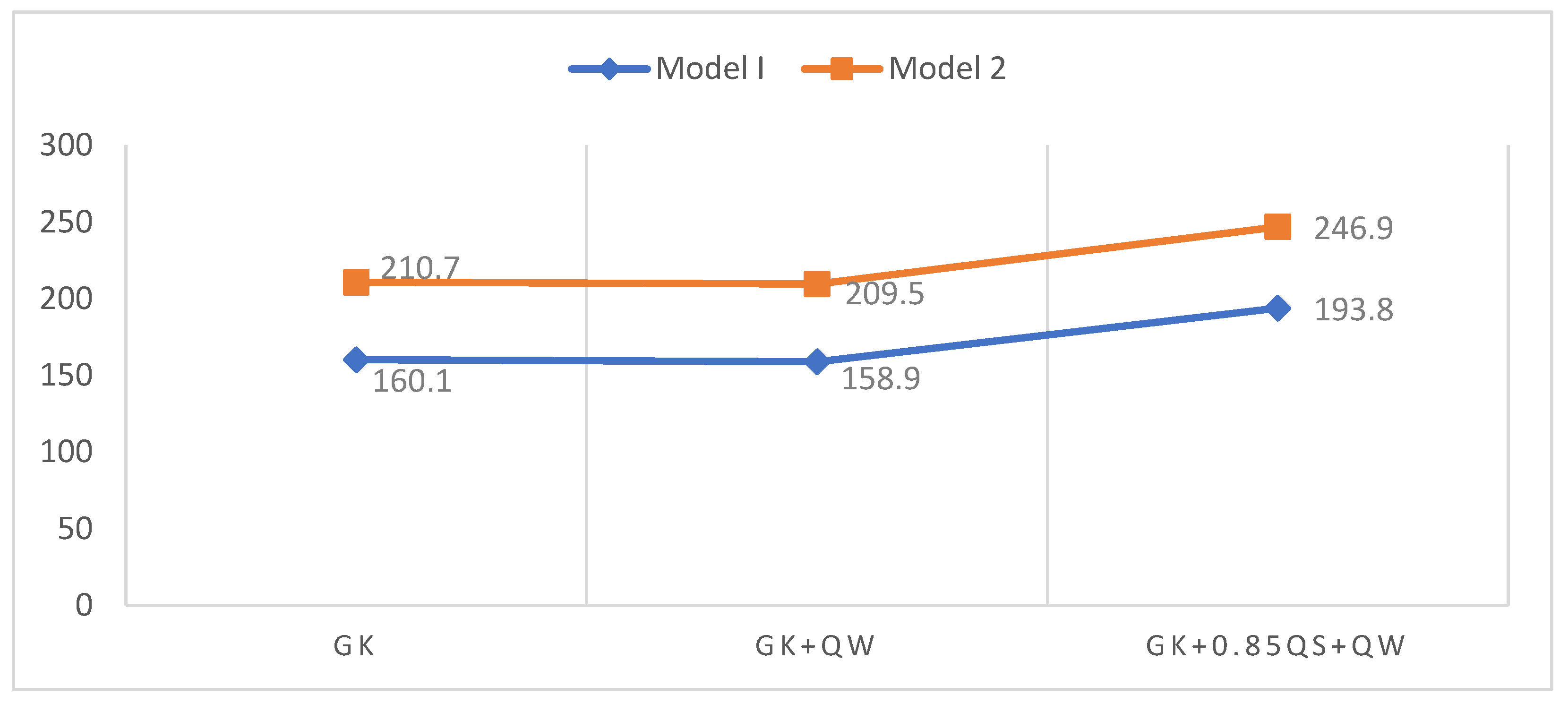
3.2.2. Analysis of the Overall Behavior of the Carport Model Structure in the Conventional State

The study tested the maximum stress values of model I and model II in the strength limit state and the maximum load that can be withstood in the OptiStruct solver. In this section, the global behavior of carport model I and model II under conventional loading will be tested and analyzed using linear and nonlinear analysis for the constructed models. According to GB50009-2012 [18], the study designed three conventional loads: GK, Gk + QW and Gk + 0.85 QS + QW.
In order to further verify the structural performance of the new energy vehicle charging pile carport model under normal operating conditions, the study analyzed the maximum stresses of model I and model II and the maximum displacement values of different axes using linear static and nonlinear static solvers.
First, the stress analysis of the model structure under conventional load.
a.
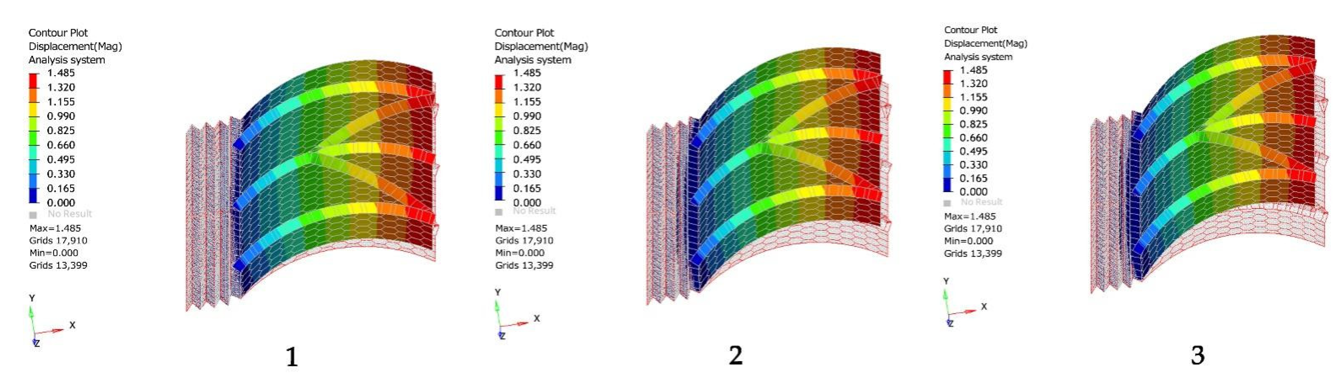
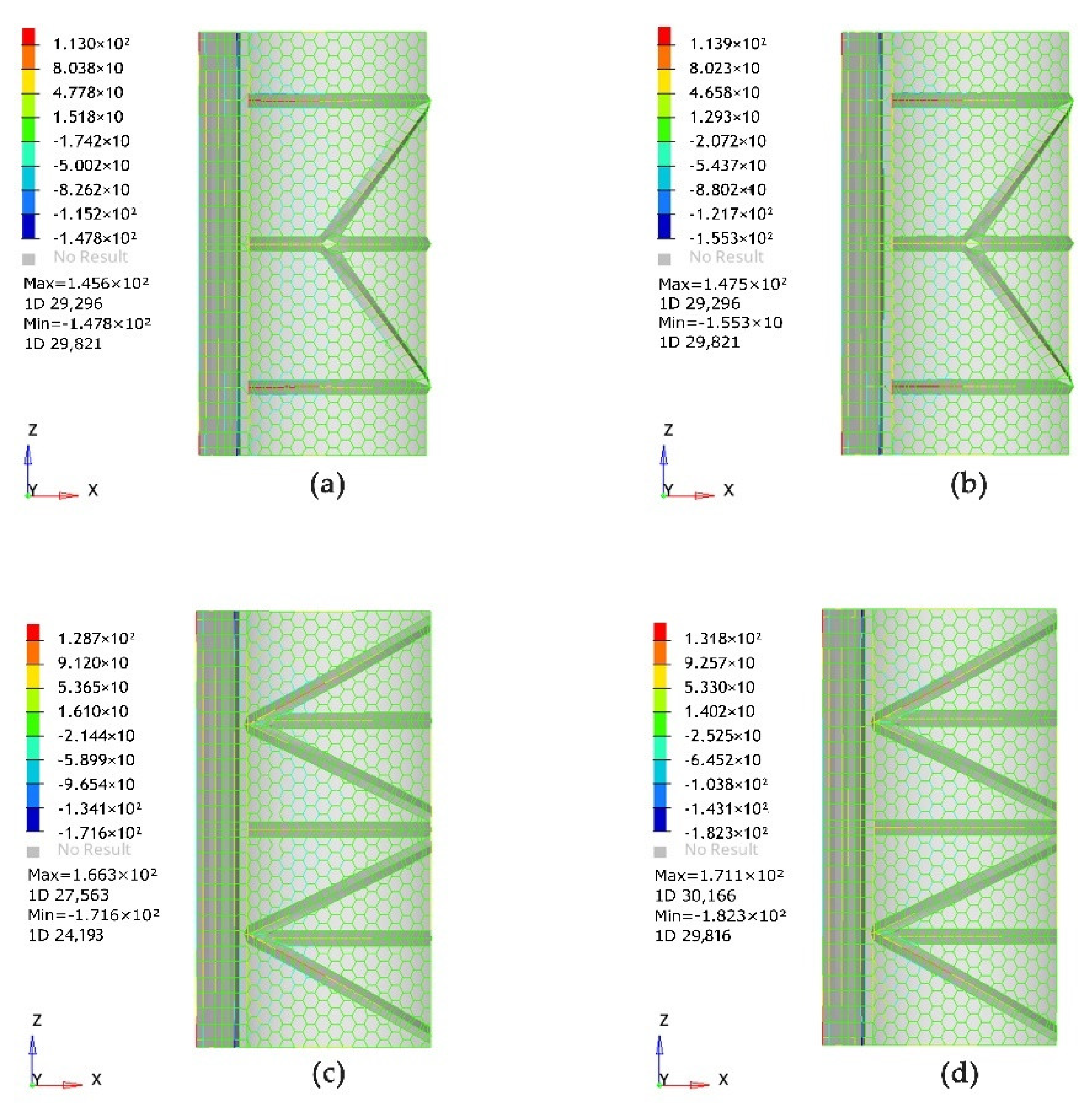
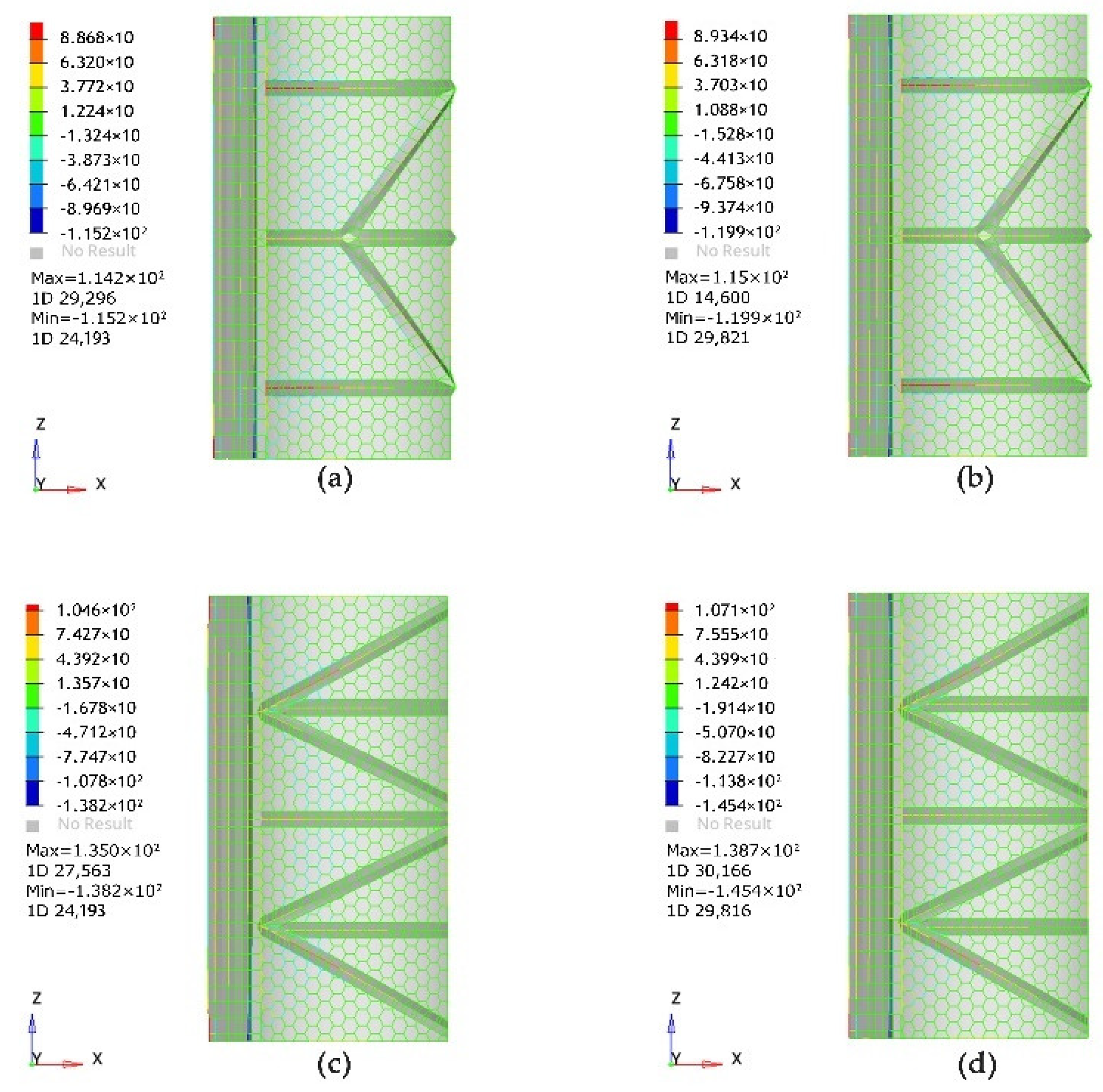
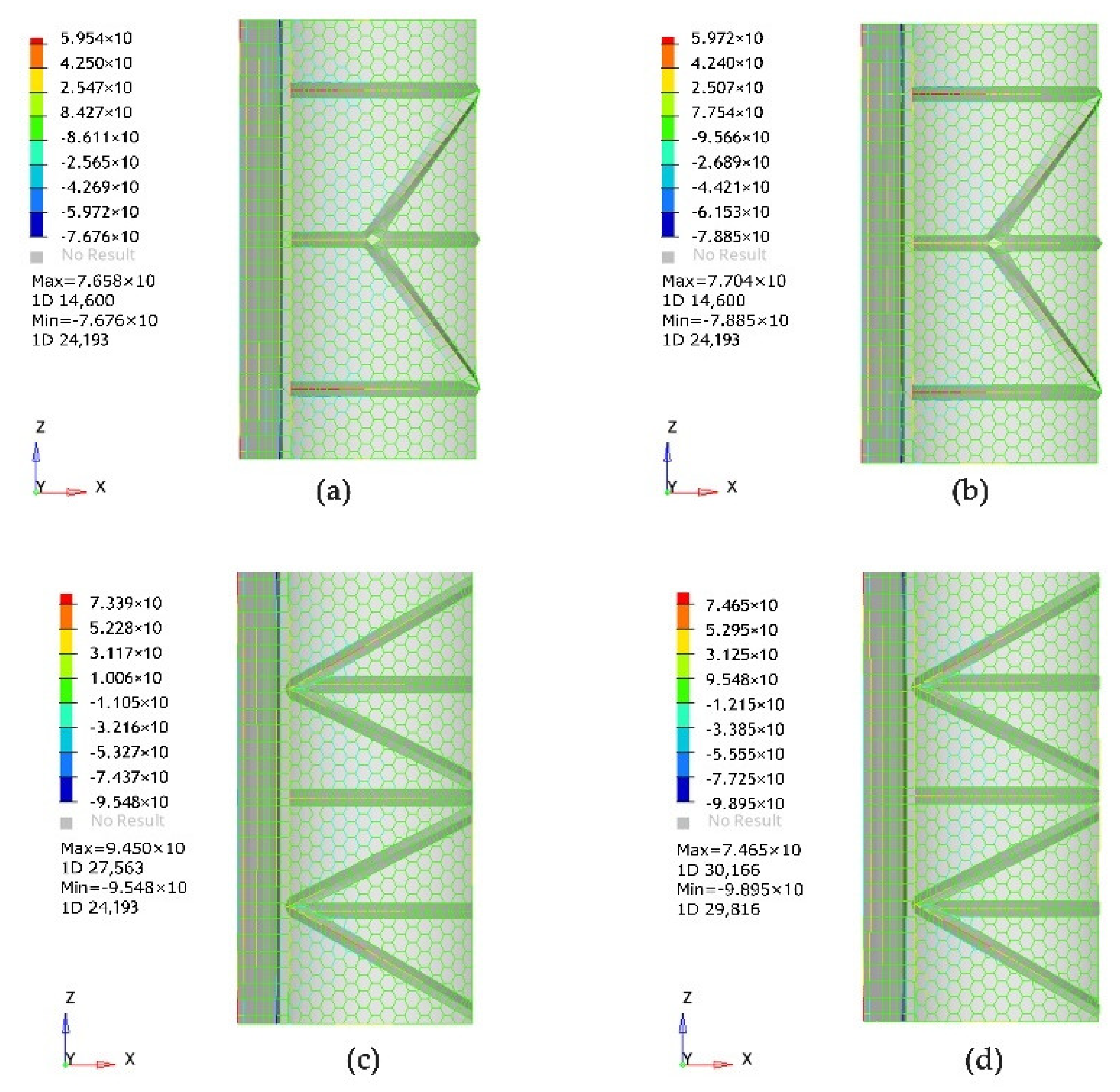
Stress analysis of the carport structure under the GK load. Figure 21 shows the total stresses of carport I and carport II under the GK load. Figure 22 shows the total stresses of carport I and carport II under the Gk + QW load. Figure 23 shows the total stresses of carport I and carport II under the Gk + 0.85 QS + QW load.
b.
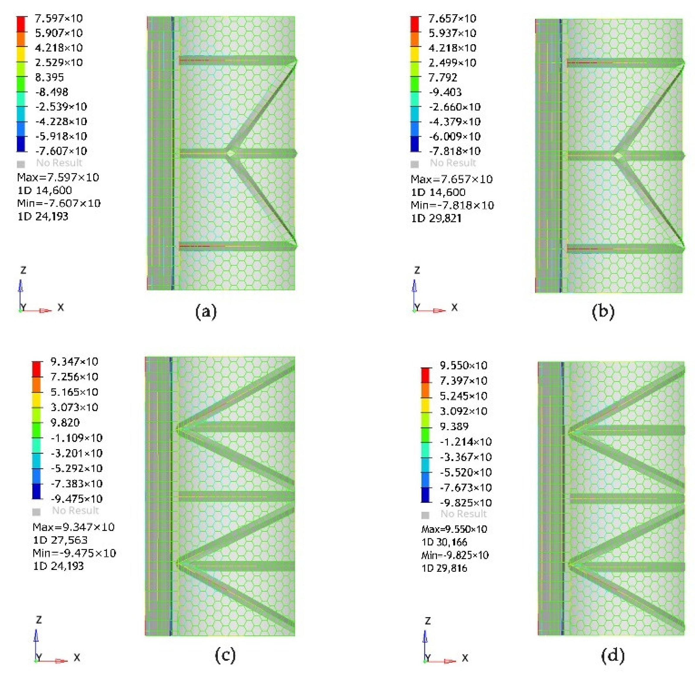
Structural performance analysis of the carport under the Gk + QW load. Figure 22 shows the total stresses of carport one and carport two under the Gk + QW load.
c.
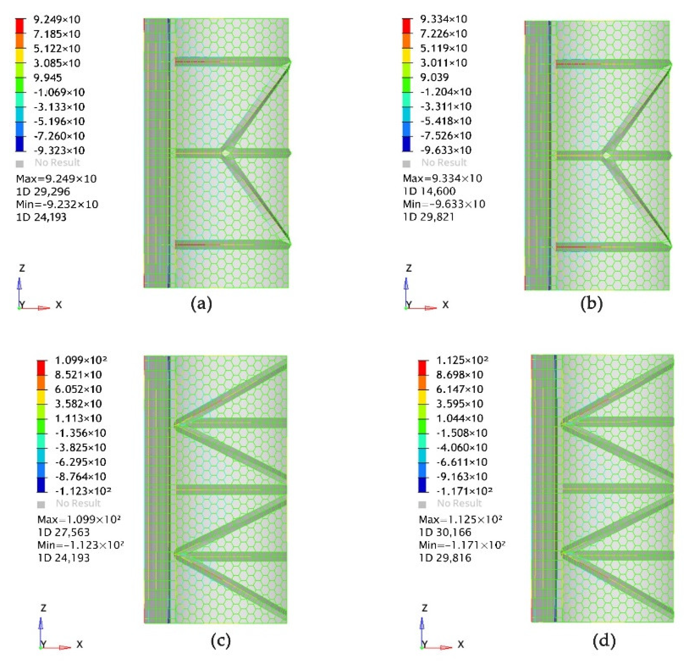
Structural performance analysis of the carport under the Gk + 0.85 QS + QW load. Figure 23 shows the total stresses of carport one and carport two under the Gk + 0.85 QS + QW load.
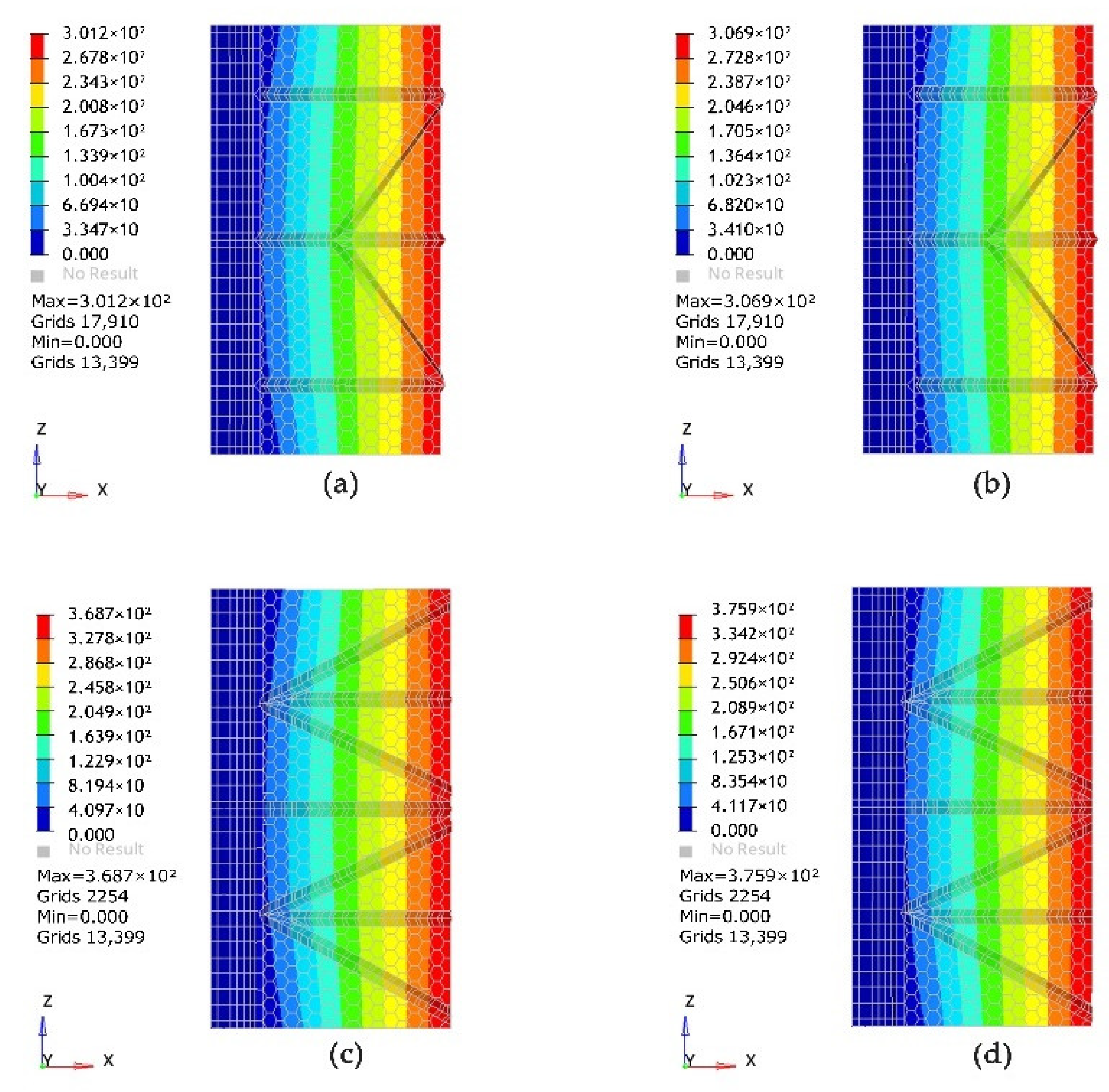
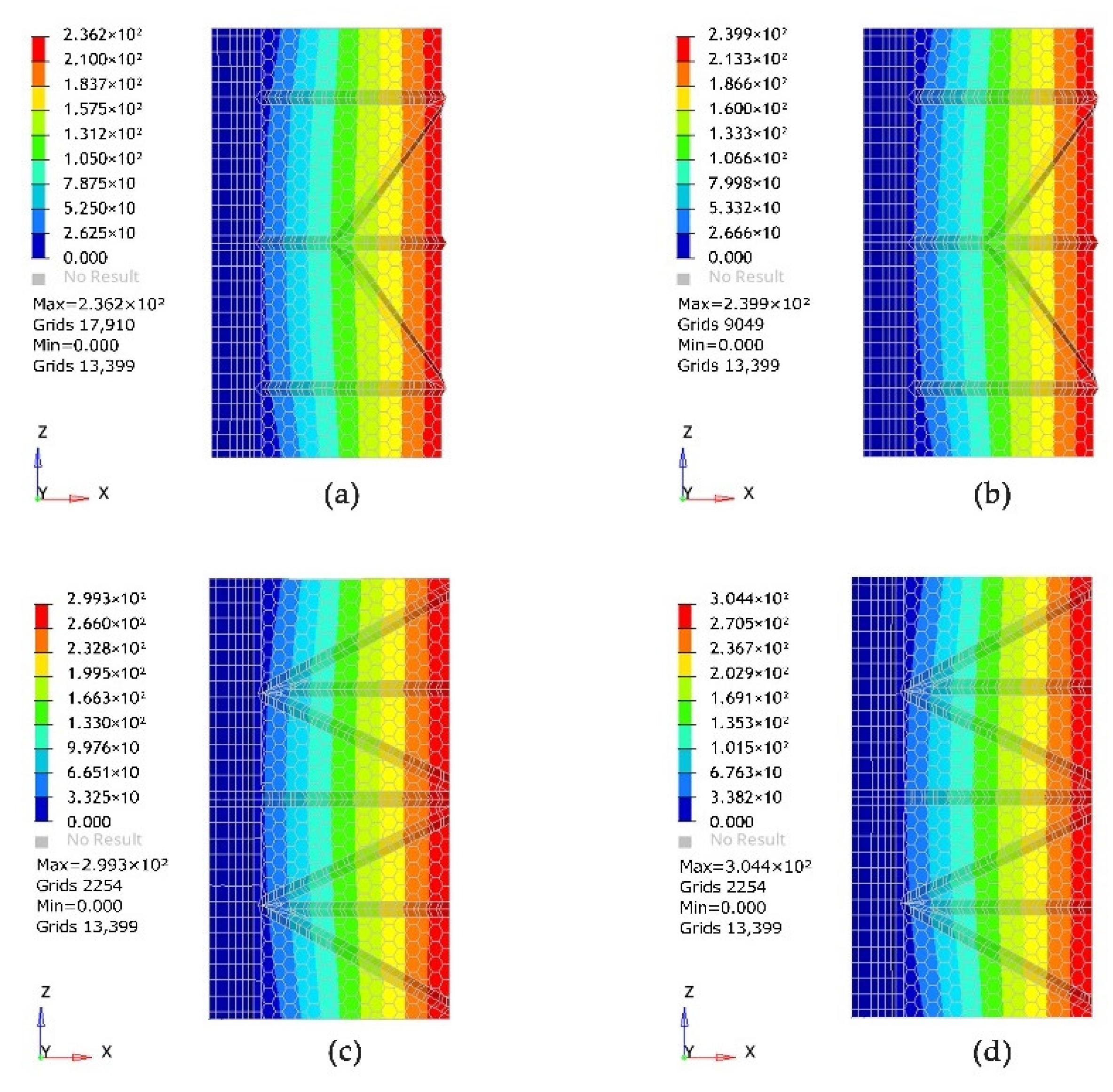
Second, the analysis of the maximum displacement value of the model under conventional load.
a.
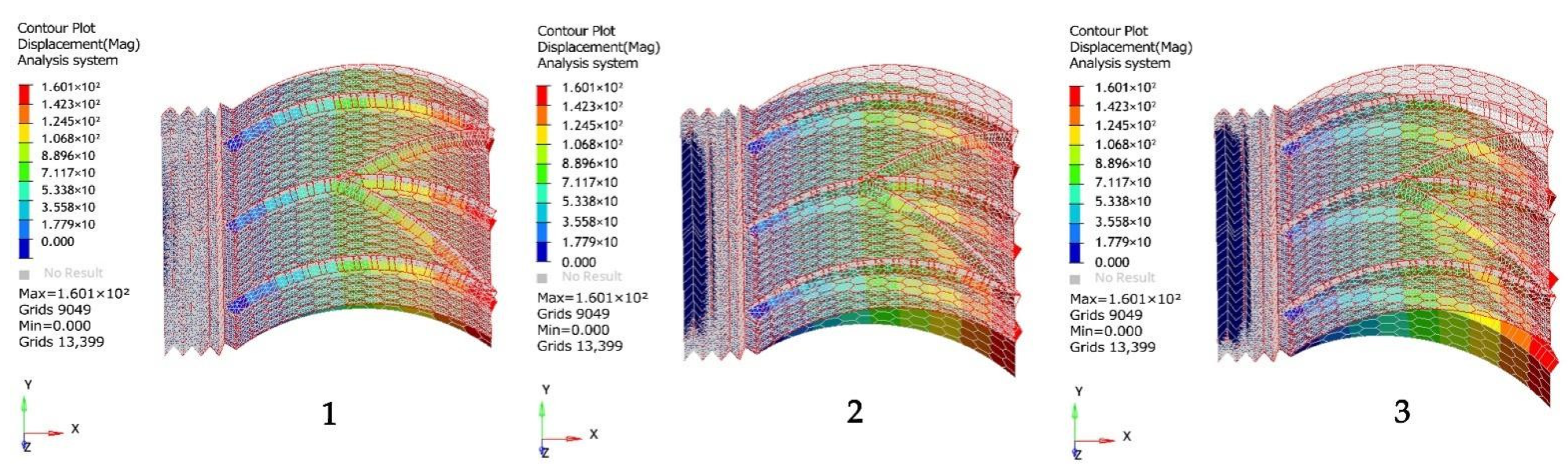
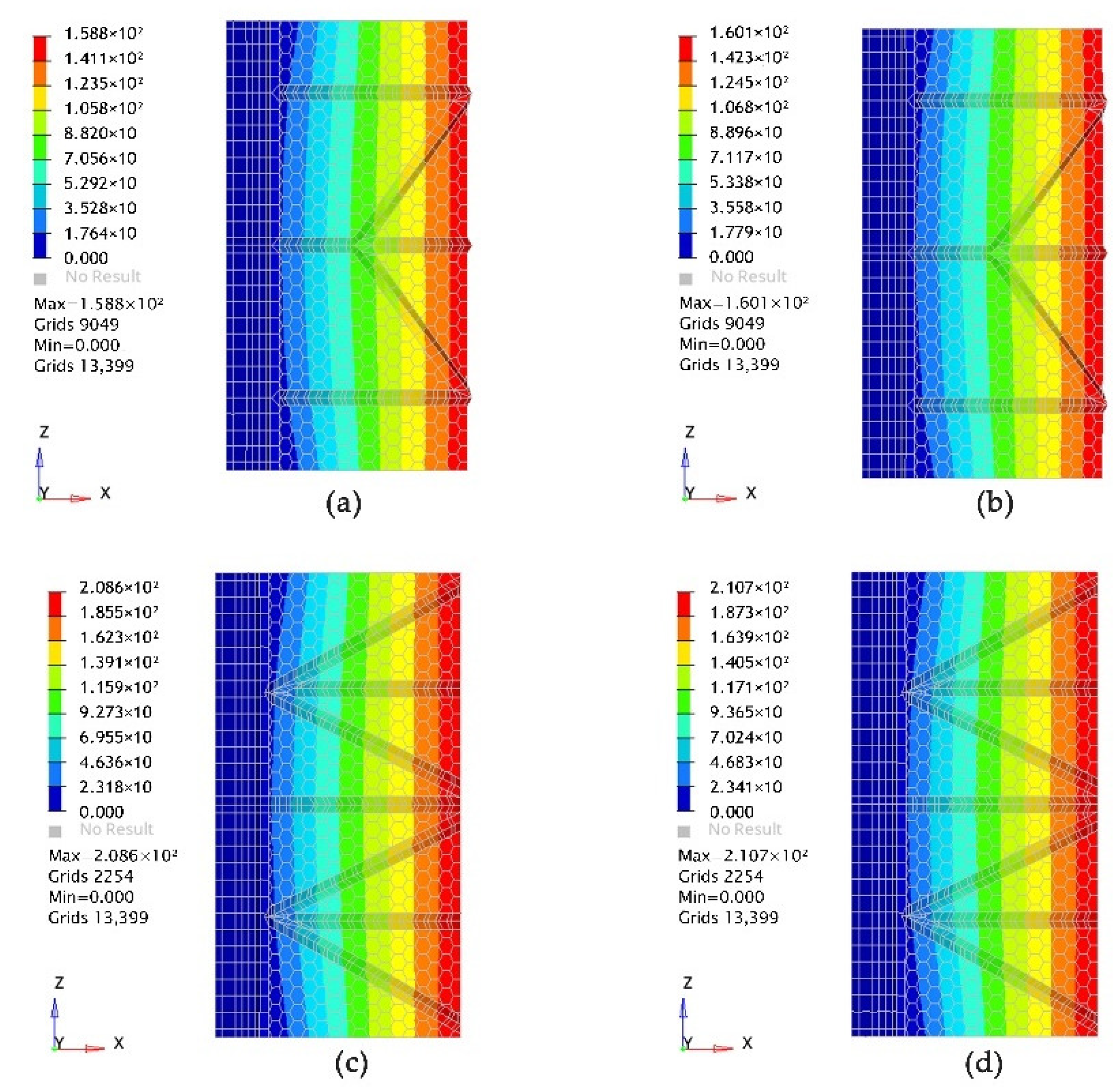
The combined displacement diagram of carport I and carport II under the GK load.
Figure 24 shows the maximum displacement diagram of carport I and carport II under the Gk load.
b.
Structural performance analysis of the carport under the Gk + QW load.
Figure 25 shows the maximum displacement diagram of carport I and carport II under the Gk + QW load.
c.
Structural performance analysis of the carport under the Gk + 0.85 QS + QW load.
Figure 26 shows the maximum displacement diagram of carport I and carport II under the Gk + 0.85 QS + QW load.
In addition, the individual directional axis displacement measurements of the two models in the conventional state were carried out and the values are shown in Table 7. Table 7 shows the values of the axial displacement in each direction for the two carports in the conventional state.

3.3. Constraints on the Optimal Design of Structural Stiffness of New Energy Vehicle Charging Pile Carport

Due to the large deformation of the carport shed roof under different load cases, and according to the actual use scenario of the car charging post carport are including pillars, in order to standardize the acquisition of real data, further research on the model structure is done to increase the numerical analysis of the model support column through the study of the carport stiffness containing the support column to get more realistic values. According to the ratio of the carport roof, we use 8 mm support column for analysis, and considering the actual situation between the carport and concrete, we will establish a new finite element model which adopts the design of fixed at one end and hinged at the other end.
From the above analysis, it can be seen that the deflection and stress values of model I and model II carports are significantly smaller than those of model II under the same loading conditions, so model I is chosen to increase the pillars for testing.
As shown in Figure 27, three pillars were added at the red point of model I and vertical displacement constraints were established. The maximum deflection and stress under permanent load and permanent plus an external load of F = 1000 N/m2 were simulated in the finite element model of model I after adding pillars and the model I map of the displacement cloud under the action of increasing pillar weight.
The map of the displacement cloud under the permanent load and an external load as well as the map of pull and compressive stress cloud under the permanent load and an external uniform load are shown in Figure 28.

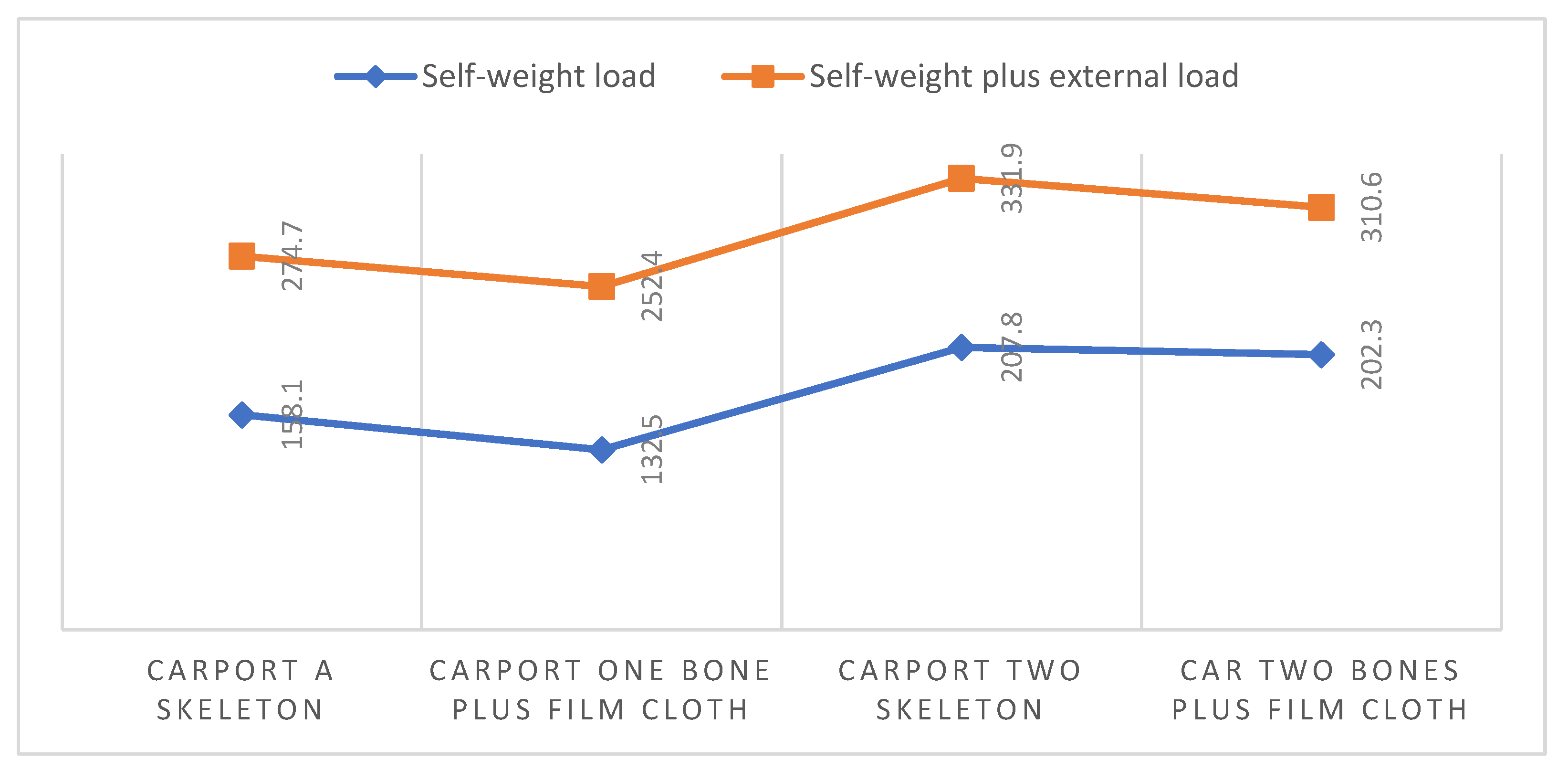
3.4. Stiffness Comparison between the Study Model and the Existing Carport

By observing the existing carports in Nanchang and surrounding areas, we found that most of the membrane-structure carports are of two types: flat-roofed and gabled-roofed structures. We measured the structural dimensions of the two carports on site and drew a plan view, as shown in Figure 5. In order to verify that the stiffness and stability of the dragonfly-inspired carports are superior to those of the existing carports, we established finite element models of the flat-roofed and gabled-roofed carports and applied ultimate loads. We compared the stiffness and stability performance of the carport based on the three-dimensional structure design of dragonfly wings with the two existing types of carports. Table 8 shows the displacement values in different axial directions under ultimate loads for the three types of carports. Based on the experimental results, we chose the experimental measurement data under nonlinear conditions.

4. Discussion

In this paper, a more stable structure of a carport for the new energy vehicle charging pile is designed based on the dragonfly wing mesh and finite element modeling is performed to analyze the maximum deflection and the maximum load capacity of the two models under different load cases. Moreover, according to the operation standard, the simulation measurement of the load capacity of the new energy vehicle charging pile carport under an ultimate load and normal load is set up.
By conducting linear and nonlinear tensile and compressive stress analysis and observing the carport at the heaviest load bearing member, the pillar is added according to the location of the load bearing member to improve and optimize the overall stiffness and load-bearing capacity of the new energy vehicle charging pile carport. The established new energy vehicle charging pile carport model improves the carport stiffness and stability.

4.1. Static Load of the New Energy Vehicle Charging Pile Carport Model

According to the known three-dimensional arching and wrinkling structure of the dragonfly wing design, two different structures of carports are established using a finite element model. From Figure 9, Figure 10 and Figure 11, it can be seen that carport one under the self-weight as well as an external load of F = 1000 N/m2, maximum displacement occurs in the front of the carport, while the self-weight load carport without the shell has a combined displacement value of 158.1 mm compared with the shell carport, which increased by 25.6 mm; the self-weight plus an external load under the action of the maximum displacement value of carport one with the shell and without the shell increases with the increase of the load, and the maximum deformation of model one is reduced from 274.7 mm to 254.4 mm under the action of surface tension after adding the shell. It can be seen from Figure 11 that the stress value of the carport with the shell is smaller than that of the carport without the shell, and a space structure is formed by the interaction of the beam and membrane cloth under the action of the self-weight and uniform load in model one. The maximum tensile and compressive stresses are all distributed at the quadrilateral wrinkles, which can transfer the load to the fixed end of the back edge.
In establishing the finite element carport model II with a constant load and uniform load, it was found that the maximum displacement value of the grid model was always larger than that of the model with the membrane, and the maximum deformation of model II was also at the front of the carport. According to Table 5, it can be seen that the stiffness of the two carports with the membrane fabric shows a small increase when considering the stress stiffening, and the displacement and stress values of model 2 are always larger than those of model 1 under the same load, so it is initially determined that the structural stiffness of model 1 is better than that of model 2. From the above figure, it can be seen that, under the effect of uniform load, the model as a whole is at the lowest point of the arch structure and the front edge of the carport is deformed the most away from the displacement constraint, and the hexagonal grid structure transmits the force to the wrinkled structure, which bears the main force of the carport. Figure 29 shows the folded trend diagram of the two carports under different loads. From the diagram, it can be seen that the overall values of the displacement of both carports under self-weight are lower than the self-weight plus an external uniform load, the overall values containing the membrane fabric are lower than the frame displacement values and the stability performance of model I under the static load is higher than that of model II.

4.2. The Ultimate Bearing Capacity of the New Energy Vehicle Charging Pile Shed Model

The two carports are subjected to load analysis under ultimate unfavorable conditions to further explore the ultimate bearing capacity of the two carports. Figure 15 shows that the maximum stress of the carport of 114.8 Mpa comes from the nonlinear analysis of carport model one, and the overall value is less than 235 Mpa, indicating that carport I does not yield under the 1.2 GK + 1.4 QW load. From the observation in the figure, it can be seen that model I and model II are under linear static analysis with a fixed restraint. The fiber stress of position beam 3 is the largest, and the most heavily stressed member of the two carports under nonlinear static is the fixed restraint position beam 4, which indicates that the maximum stress point of the carport needs further stability enhancement. Figure 16 shows that the displacement value of model II under the 1.2 GK + 1.4 QW load is always larger than that of model I. The results of the combined displacement analysis and stress analysis show the same trend, and the value under the nonlinear state is always larger than that of the linear values. Figure 17 and Figure 18 show that the nonlinear stress values of carport I and carport II under the load of 1.2 Gk + 1.4 QL + 1.4 × 0.85 QW are greater than the linear stress, and the maximum stress point under the linear static analysis of both carports presents the same position as under the load of 1.2 GK + 1.4 QW; the maximum displacement value of nonlinear model one is 306.9 mm, which is 116 mm higher compared to the load of 1.2 GK + 1.4 QW. The maximum displacement value is 306.9 mm, which is 116 mm higher than the load of 1.2 GK + 1.4 QW. It can be seen that the carport is affected by the live load and wind load, and the carport structure is controlled by yielding.
Figure 19 and Figure 20 show that, under the 1.2 Gk + 1.4 × 0.85 QS + 1.4 QW load, the maximum stress of the carport I fiber is 155.2 Mpa and the carport II fiber is 138.7 Mpa, both of which are less than 235 Mpa, indicating that the shed member will not yield under the load of 1.2 Gk + 1.4 × 0.85 QS + 1.4 QW. In this case, the wind load acts on the roof plane of the shed. Figure 19 shows that, when the shed is subjected to a large wind load, the bearing capacity of the members is very sensitive to the wind load.
As shown in Figure 20, the maximum displacement value of carport I is 239.9 mm and the displacement value of carport II is 304.4 mm, with the difference between them of 64.5 mm. From Table 6, it can be seen the displacement values in the 1.2 Gk + 1.4 QL + 1.4 × 0.85 QW load for carport I and carport II for each axial value are overall on an upward trend. The difference between the performance of the two models can be seen from the line graph in Figure 30, which clearly shows that, with the increase of the load, the displacement values of the two carports also rise gradually, but the displacement values of carport I are always smaller than those of carport II, and the changes of the different load values all indicate that the wind load does play an important role in the structural performance of the carport.
Through the analysis under the strength limit state, the performance of the carport structure designed in this study is in good condition under the ultimate load, which is lower than the ultimate load capacity of the steel structure, where all steel members are in an elastic state and all structural deformation is small. The dragonfly wing deformation showed an overall deformation trend and the carport structure also showed an overall deformation without plastic deformation, and the structure did not have an overload capacity, so the carport structure designed in the ultimate load state is safe. It can be seen from the figure above that the wind load has a great influence on the buckling load of the beam, and the bearing capacity of the beam has a tendency to decrease, so it is necessary to further explore the effect of the wind load on the building.

4.3. Conventional Load-Bearing Capacity of New Energy Vehicle Charging Pile Carport Model

From the previous section, it is concluded that the stability of the two carports can be maintained well under ultimate load conditions. According to GB50009-2012 [18], three kinds of conventional loads are designed and the stress and displacement are analyzed in this section. In order to simplify the carport model to obtain more accurate simulation values, we assume that the membrane structure on the surface of the carport is smooth enough and the wind friction on the membrane fabric is small enough to be ignored. Figure 21, Figure 22 and Figure 23 show the axial stress diagrams of the two carports under the Gk, Gk + QW and Gk + 0.85 QS + QW loads, which show that the nonlinear data results of the two carports under the three states are larger than the linear values, and the carport with the stress values also show an increasing trend as the load increases. The maximum stress value of carport I under the Gk load is 78.18 Mpa and the difference between the maximum stress of carport II is 20.77 Mpa, where the stress value decreases with the load value. The heaviest force member of the two carports under the nonlinear state is the fixed restraint position 3 crossbeam, while the heaviest force at the fixed restraint displacement position 4 crossbeam of the two carports is under the linear analysis, and the heaviest force point of the ultimate load presents the same position. The yield stress of the selected cross-section of the model is 235 Mpa, so the designed structure will not be plastic-deformed under the limit state of normal use. Due to the addition of the asymmetric wind load, the maximum axial stress of the load combination of Gk + 0.85 and QS + QW for carport I is 19% higher than that under the Gk load and 15% higher than that for carport II. The results of the axial stress analysis are consistent with those of the analysis under the ultimate load, which again indicates that the structural mechanical behavior of the carport beam under the wind load has a greater influence.
By analyzing the displacement values of the carport under different loads, and according to the steel structure design standard GB 50017-2017, it can be known that the horizontal displacement limit of single-story steel structure is H/400, and, as shown in Figure 24, the maximum lateral displacement of carport I and carport II blocks under the Gk load is obviously smaller than the maximum allowable displacement, where the difference between the combined displacement value of carport I and carport II is 50.6 mm and the maximum deformation is located at the front of the carport. As shown in Figure 25, the nonlinear combined displacement values of the two carports under the Gk + Qw load are 158.9 mm and 209.5 mm, respectively, and carport II exhibits higher displacement values than carport I, which may be due to the more uniform dispersion of forces and better stability performance of the carport I structure and the larger wrinkle span of carport II, which leads to higher gravity loads. In the Gk + 0.85 QS + QW load, the two carports show higher structural displacements under the snow load and wind load, and the sudden rise in the displacement of carport I can be explained by the lateral load of the wind load and the vertical load of the snow load; the largest displacement values in the combined displacement can be seen in Table 7, where the two carports show an increase in the displacement values as the load increases.
From Figure 31, it can be seen that the difference between the displacement values of carport I and carport II under nonlinearity for the self-weight load and the self-weight plus the wind load does not vary much under favorable conditions, which is more influenced by snow load. From this section, we observe that the constant load and snow load in both load combinations are configured in the vertical direction, which has no obvious effect on the wrinkled and arched structures of the two carports; however, the wind load acts above the surface of the structure, and the wind load applied to the arched carport is concentrated at a certain point with serious force, resulting in the large offset distance of the carport structure. The reason why the stiffness of carport II in the experimental results is always lower than that of carport I may also be because carport II has no central support point and the span is too large. In model II, the wrinkled structure stands on top of the arching structure to bear the main force, but the wrinkled structure is not enough to support the weight of the front at too long a distance, while the central triangle of carport I plays the role of uniformly dispersing the force, subdividing the middle two regions and transferring the force of the carport to the wrinkles.

4.4. The Deflection of the New Energy Vehicle Charging Post Carport

Based on the actual situation of the carport, three 8 mm thick supporting columns of the ideal model were added. According to Figure 28, the combined displacement value of carport I under constant load is 79.18 mm, which significantly enhances the stiffness of 53.32 mm compared to the carport without pillars.
With the increase of the load, the effect of the struts was more obvious and the stability of the shed was greatly enhanced. The maximum stress value of the first shed after the increase of the struts was 284.3 Mpa, while the stress value of unsupported shed was 110.3 Mpa. The charging carport model of the new energy vehicle after adding pillars better disperses the force of wrinkling along the rear edge of the carport and the force of wrinkling on the arch surface of the carport.

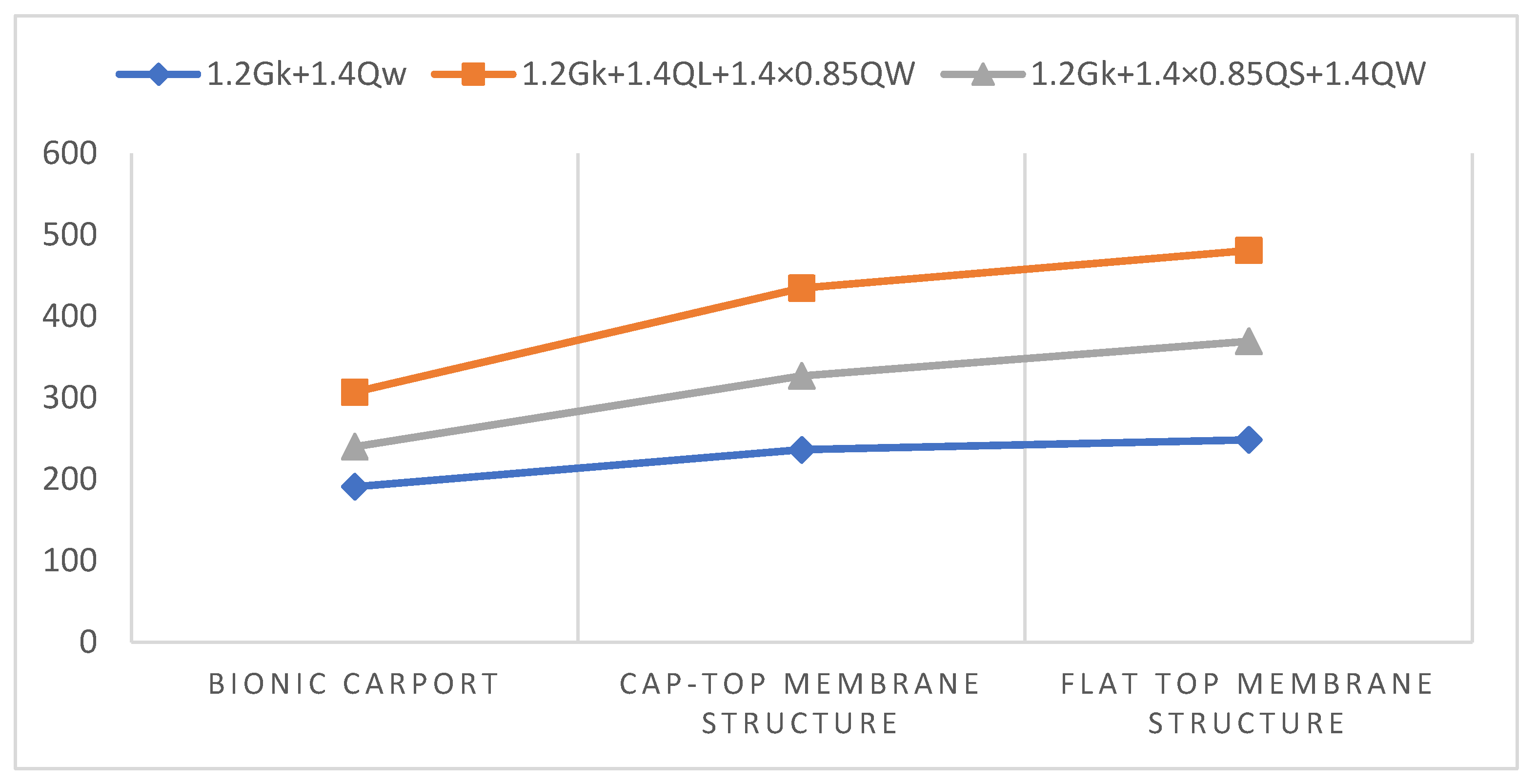
4.5. Comparison of Different Types of Carport Stiffness

To verify the practicality of the new energy vehicle charging station shelter proposed in this paper, we selected two common membrane structure shelters for stiffness–displacement testing. Based on Table 8, we plotted the curve chart.
As shown in Figure 32, under the same load, the displacement value of the bionic shelter for the new energy vehicle charging station is always smaller than that of the two types of shelters observed and modeled in the field. Additionally, the displacement of the flat-top shelter is always larger than the other two types, and the trend of all three shelters’ curves increases with the increase of the load. As can be seen from Figure 32, the displacement values of the bionic carport of the new energy vehicle charging pile under the same load are always smaller than those of the two types of carports modeled in the field study, and the displacement of the flat-roofed carport is always at a larger value, while the trend of all three carport lines increases with the increase of the load.

5. Conclusions

This study designed two different types of vehicle shed models based on the three-dimensional structure of dragonfly wings, according to the conventional requirements for new energy vehicle charging station sheds. The aim was to analyze the stress and displacement values, as well as the maximum critical load that the sheds could withstand under different load conditions, in order to optimize their stiffness and stability.
Based on the three-dimensional structure of dragonfly wings, the study divided the shed into two different structural finite element models. Three different load experiment scenarios, including ultimate load and conventional load, were set according to load standards. These models were then imported into the OptiStruct finite element software for mechanical experimental analysis. The numerical design results show:
  • Under a constant load, the stiffness of the membrane-covered carport is significantly higher than that of the skeleton-covered carport, and the displacement values of both show a decreasing trend.
  • Under the permanent and external uniformly distributed load, model 1 exhibits better compression resistance and higher stress values compared to model 2. The maximum displacement of both models under uniform load occurs at the front edge of the carport. In the stress plot, it is observed that both carports transfer the force to the corrugated structure, which bears the main load.
  • The stability performance of the carports decreases as the bearing capacity increases under different operating conditions. Three types of extreme loads were studied and designed, and it was found that, under the ultimate strength limit state, the displacement values of both carports increased linearly with the increase of the load.
  • The displacement values under the load of 1.2 GK + 1.4 QL + 1.4 × 0.85 QW show a significant increase, indicating that the key load in the ultimate strength limit state is the wind load, which acts on the outer surface of the structure rather than inward.
  • Under the ultimate load, both carports are within the yield stress of the steel members, indicating that both carports meet the requirements of the carport under adverse conditions. The structural displacement is controlled by the gravitational load, and the total displacement is located at the front of the carport.
  • Based on the actual situation, we added pillars at the force-bearing points of the carport and found that it greatly improved the rigidity of the carport.
  • Field measurements and modeling were conducted on two common membrane-structure carports. The results showed that our newly designed model for the new energy vehicle charging station carport had stronger stability and compressive performance compared to conventional flat-top and gable-top carports.
The study proposes an improved model of the new energy vehicle charging station canopy structure that has better stiffness than current market canopy structures. Taking inspiration from the biomimetic dragonfly wing grid and using optimized structural design and material selection, the canopy model shows smaller overall displacement values under extreme loading conditions and a significantly improved durability. Furthermore, it further proves the advantages of using a lattice shell structure that is lightweight and has high reusability. This result has important implications for the design and improvement of new energy charging station canopies. In the future, based on these research results, further exploration of optimized canopy design schemes can be conducted to improve canopy stability and compressive performance, thereby better meeting user needs. The designed new energy vehicle charging station canopy in this study has certain applicability. Although some structural improvements have been proposed for the design of the new energy vehicle charging station canopy, the numeric design experiments had a relatively small canopy area, particularly for the influence of structural deflection on the connected canopy, the effect of new materials on canopy stiffness and the height of canopy wrinkles and arching under different environmental conditions, as well as wind resistance, which requires further research.

Author Contributions

Conceptualization, C.L. and Y.W.; methodology, Y.W. and X.W.; validation, C.L., Y.W. and X.M.; formal analysis, Y.W.; investigation, C.L.; formal analysis, C.L. and X.M.; investigation, Y.W.; data curation, Y.W. and C.L.; writing—original draft preparation, C.L. and Y.W.; writing—review and editing, Y.W. and X.W.; visualization, C.L. and Y.W. All authors have read and agreed to the published version of the manuscript.

Funding

This research was funded by Jiangxi Social Science Planning Project (22YS02), the Key Research Base Project of Humanities and Social Sciences in Jiangxi Province Universities (JD22090) and the Jiangxi Provincial Postgraduate Innovation Special Fund Project in 2022 (YC2022—s067).

Data Availability Statement

Data are available upon request.

Acknowledgments

We are grateful for the generous support provided by Key Research Base for Humanities and Social Sciences in Jiangxi Province Universities. We thank the reviewers for their valuable feedback.

Conflicts of Interest

The authors declare no conflict of interest.

References

  1. Chen, J.; Ma, K.J.; Xiao, J.C.; Wei, Y.H.; Chen, H.N.; Lu, Y.Q. Prefabricated construction process and unloading monitoring of space steel grid cassettle structure multi-storey large-span gymnasium. Int. J. Electr. Eng. Educ. 2021, 1–12. [Google Scholar] [CrossRef]
  2. Huang, W.; Wu, C.; Hu, J.; Gao, W. Weaving structure: A bending-active gridshell for freeform fabrication. Autom. Constr. 2022, 136, 114804. [Google Scholar] [CrossRef]
  3. Tahmasebinia, F.; Ma, Y.; Joshua, K.; Sepasgozar, S.; Yu, Y.; Li, J.; Sepasgozar, S.; Marroquin, F. Sustainable Architecture Creating Arches Using a Bamboo Grid Shell Structure: Numerical Analysis and Design. Sustainability 2021, 13, 2598. [Google Scholar] [CrossRef]
  4. Mahphood, A.; Arefi, H. Grid-based building outline extraction from ready-made building points. Autom. Constr. 2022, 139, 104321. [Google Scholar] [CrossRef]
  5. Ozkal, F.A.; Cakir, F.; Arkun, A. Finite element method for optimum design selection of carport structures under multiple load cases. Adv. Prod. Eng. Manag. 2016, 11, 287–298. [Google Scholar]
  6. Rezvani Tavakol, M.; Yarmohammad Tooski, M.; Jabbari, M.; Javadi, M. Effect of graphene nanoparticles on the strength of sandwich structure inspired by dragonfly wings under low-velocity impact. Polym. Compos. 2021, 42, 5249–5264. [Google Scholar] [CrossRef]
  7. Wang, Y.; He, X.; He, G.; Wang, Q.; Chen, L.; Liu, X. Aerodynamic performance of the flexibility of corrugated dragonfly wings in flapping flight. Acta Mech. Sin. 2022, 38, 322038. [Google Scholar] [CrossRef]
  8. Wang, C.; Zhang, R.; Zhou, C.; Sun, Z. Numerical Investigation on Flapping Aerodynamic Performance of Dragonfly Wings in Crosswind. Int. J. Aerosp. Eng. 2020, 2020, 7325154. [Google Scholar] [CrossRef]
  9. Xu, J.; Liu, T.; Zhang, Y.; Zhang, Y.; Wu, K.; Lei, C.; Fu, Q.; Fu, J. Dragonfly wing-inspired architecture makes a stiff yet tough healable material. Matter 2021, 4, 2474–2489. [Google Scholar] [CrossRef]
  10. Mintchev, S.; Shintake, J.; Floreano, D. Bioinspired dual-stiffness origami. Sci. Robot. 2018, 3, eaau0275. [Google Scholar] [CrossRef] [PubMed]
  11. Li, X.-J.; Zhang, Z.-H.; Liang, Y.-H.; Ren, L.-Q.; Jie, M.; Yang, Z.-G. Antifatigue properties of dragonflyPantala flavescenswings. Microsc. Res. Tech. 2014, 77, 356–362. [Google Scholar] [CrossRef]
  12. Bysiec, D. Sustainable Shaping of Lightweight Structures Created According to Different Methods. Sustainability 2023, 15, 3236. [Google Scholar] [CrossRef]
  13. Dede, T.; Atmaca, B.; Grzywinski, M.; Rao, R.V. Optimal design of dome structures with recently developed algorithm: Rao series. Structures 2022, 42, 65–79. [Google Scholar] [CrossRef]
  14. Degertekin, S.O.; Bayar, G.Y.; Lamberti, L. Parameter free Jaya algorithm for truss sizing-layout optimization under natural frequency constraints. Comput. Struct. 2021, 245, 106461. [Google Scholar] [CrossRef]
  15. Feng, S.; Zhang, W.; Meng, L.; Xu, Z.; Chen, L. Stiffener layout optimization of shell structures with B-spline parameterization method. Struct. Multidiscip. Optim. 2021, 63, 2637–2651. [Google Scholar] [CrossRef]
  16. Pavlovic, A.; Sintoni, D.; Fragassa, C.; Minak, G. Multi-Objective Design Optimization of the Reinforced Composite Roof in a Solar Vehicle. Appl. Sci. 2020, 10, 2665. [Google Scholar] [CrossRef]
  17. Li, N.; Zhang, D.-Q.; Liu, H.-T.; Li, T.-J. Optimal design and strength reliability analysis of pressure shell with grid sandwich structure. Ocean Eng. 2021, 223, 108657. [Google Scholar] [CrossRef]
  18. Liu, F.; Feng, R.; Tsavdaridis, K.D.; Yan, G. Designing efficient grid structures considering structural imperfection sensitivity. Eng. Struct. 2019, 204, 109910. [Google Scholar] [CrossRef]
  19. Arruda, M.R.T.; Castro, L.M.S. Non-linear dynamic analysis of reinforced concrete structures with hybrid mixed stress finite elements. Adv. Eng. Softw. 2021, 153, 102965. [Google Scholar] [CrossRef]
  20. Elsanadedy, H.M.; Al-Salloum, Y.A.; Alrubaidi, M.A.; Almusallam, T.H.; Abbas, H. Finite element analysis for progressive collapse potential of precast concrete beam-to-column connections strengthened with steel plates. J. Build. Eng. 2020, 34, 101875. [Google Scholar] [CrossRef]
  21. Pallares-Muñoz, M.R.; Paya-Zaforteza, I.; Hospitaler, A. A new methodology using beam elements for the analysis of steel frames subjected to non-uniform temperatures due to fires. Structures 2021, 31, 462–483. [Google Scholar] [CrossRef]
  22. Yu, P.; Yang, Q.; Law, S.-S. Lateral behavior of heritage timber frames with loose nonlinear mortise-tenon connections. Structures 2021, 33, 581–592. [Google Scholar] [CrossRef]
  23. Bagha, A.A.K.; Bahl, S. Finite element analysis of VGCF/pp reinforced square representative volume element to predict its mechanical properties for different loadings. Mater. Today Proc. 2020, 39, 54–59. [Google Scholar] [CrossRef]
  24. Dandekar, K.; Raju, B.I.; Srinivasan, M.A. 3-D Finite-Element Models of Human and Monkey Fingertips to Investigate the Mechanics of Tactile Sense. J. Biomech. Eng. 2003, 125, 682–691. [Google Scholar] [CrossRef]
  25. Zaid, M.; Mishra, S.; Rao, K.S. Finite Element Analysis of Static Loading on Urban Tunnels; Springer: Singapore, 2020. [Google Scholar]
  26. Hou, D.; Zhong, Z. Comparative analysis of deformation behaviors of dragonfly wing under aerodynamic and inertial forces. Comput. Biol. Med. 2022, 145, 105421. [Google Scholar] [CrossRef] [PubMed]
  27. Xu, F.; Wang, J.; Hua, L. Multi-objective biomimetic optimization design of stiffeners for automotive door based on vein unit of dragonfly wing. Proc. Inst. Mech. Eng. Part C J. Mech. Eng. Sci. 2021, 236, 4551–4564. [Google Scholar] [CrossRef]
  28. GB 50009-2012; Code for Structural Loading of Buildings. Ministry of Housing and Urban-Rural Development: Beijing, China, 2012.
  29. Suizi, J.; Wanlin, C.; Yuchen, Z. Low reversed cyclic loading tests for integrated precast structure of lightweight wall with single-row reinforcement under a lightweight steel frame. R. Soc. Open Sci. 2018, 5, 180321. [Google Scholar] [CrossRef] [PubMed]
  30. Tartaglia, R.; Milone, A.; Prota, A.; Landolfo, R. Seismic Retrofitting of Existing Industrial Steel Buildings: A Case-Study. Materials 2022, 15, 3276. [Google Scholar] [CrossRef]
  31. Wang, Z. Integral Fire Protection Analysis of Complex Spatial Steel Structure Based on Optimized Gaussian Transformation Model. Comput. Intell. Neurosci. 2022, 2022, 6127225. [Google Scholar] [CrossRef]
  32. Balasbaneh, A.T.; Ramli, M.Z. A comparative life cycle assessment (LCA) of concrete and steel-prefabricated prefinished volumetric construction structures in Malaysia. Environ. Sci. Pollut. Res. Int. 2020, 27, 43186–43201. [Google Scholar] [CrossRef]
  33. He, Y.; Zhu, M.; Zhao, Y.; Li, X. Influence of different cable–membrane connection models on wind-induced responses of an air supported membrane structure with orthogonal cable net. Thin Walled Struct. 2022, 180, 109840. [Google Scholar] [CrossRef]
  34. Zhang, C.; Yang, J.; Li, Y.; Song, J.; Guo, J.; Fang, Y.; Yang, X.; Yang, Q.; Wang, D.; Deng, X. Vapor–Liquid Transition-Based Broadband Light Modulation for Self-Adaptive Thermal Management. Adv. Funct. Mater. 2022, 32, 48. [Google Scholar] [CrossRef]
  35. Tian, G.; Fan, Y.; Gao, M.; Wang, H.; Zheng, H.; Liu, J.; Liu, C. Indoor thermal environment of thin membrane structure Buildings: A review. Energy Build. 2021, 234, 110704. [Google Scholar] [CrossRef]
  36. Zhang, X.; Gao, W.; Li, Y.; Wang, Z.; Ushifusa, Y.; Ruan, Y. Operational Performance and Load Flexibility Analysis of Japanese Zero Energy House. Int. J. Environ. Res. Public Health 2021, 18, 6782. [Google Scholar] [CrossRef]
  37. Segarra, E.L.; Ruiz, G.R.; Bandera, C.F. Probabilistic Load Forecasting for Building Energy Models. Sensors 2020, 20, 6525. [Google Scholar] [CrossRef] [PubMed]
  38. Xu, J.; Xu, H.; Zeng, C.; Xie, C.; Guo, J. CFD simulation study on wind load of perforated traffic sign board. PLoS ONE 2020, 15, e0240927. [Google Scholar] [CrossRef]
  39. Cheon, D.J.; Kim, Y.C.; Lee, J.H.; Yoon, S.W. Experimental Investigation of Wind Pressure Characteristics for Cladding of Dome Roofs. Materials 2021, 14, 5266. [Google Scholar] [CrossRef] [PubMed]
  40. Domede, N.; Pena, L.; Fady, N. Historical review of lighthouse design under wind load: The Ile Vierge lighthouse. Philos. Trans. R. Soc. A Math. Phys. Eng. Sci. 2019, 377, 20190167. [Google Scholar] [CrossRef]
  41. Aksoylu, C.; Özkılıç, Y.O.; Arslan, M.H. Damages on prefabricated concrete dapped-end purlins due to snow loads and a novel reinforcement detail. Eng. Struct. 2020, 225, 111225. [Google Scholar] [CrossRef]
  42. Milošević, V.S.; Marković, B.L.; Bedon, C. Comparison of Point and Snow Load Deflections in Design and Analysis of Tensile Membrane Structures. Adv. Civ. Eng. 2020, 2020, 8810085. [Google Scholar] [CrossRef]
  43. Jovanović, B.; Van Coile, R.; Hopkin, D.; Elhami Khorasani, N.; Lange, D.; Gernay, T. Review of Current Practice in Probabilistic Structural Fire Engineering: Permanent and Live Load Modelling. Fire Technol. 2021, 57, 1–30. [Google Scholar] [CrossRef]
  44. Fu, X.; Li, H.-N.; Li, G.; Dong, Z.-Q. Fragility analysis of a transmission tower under combined wind and rain loads. J. Wind. Eng. Ind. Aerodyn. 2020, 199, 104098. [Google Scholar] [CrossRef]
Figure 1. Dragonfly wing sample picture.
Buildings 13 01071 g001
Figure 2. Two types of floor plans based on the characteristics of dragonfly wing mesh structure. (a) shows the grid plan of carport I, (b) shows the grid plan of carport II.
Buildings 13 01071 g002
Figure 3. The design of two new energy vehicle charging post carports through the dragonfly wing grid study, with (a) a floor plan for model 1, (b) a floor plan for model 2 and (c) an elevation plan for model 1 and model 2.
Buildings 13 01071 g003
Figure 4. A schematic diagram of the carport with constraint conditions.
Buildings 13 01071 g004
Figure 5. The plan views of the two types of carport structures based on field measurements. (a) The plan view of the hat-shaped carport; (b) The plan view of the flat-topped carport.
Buildings 13 01071 g005
Figure 6. The snow distribution coefficient of the arch roof.
Buildings 13 01071 g006
Figure 7. Deformation of the roof under vertical load. 1 is the initial deformation of the roof, 2 is the middle deformation of the roof, 3 is the severe deformation of the roof.
Buildings 13 01071 g007
Figure 8. Deformation of ceiling under lateral load.1 is the initial roof lateral deformation, 2 is the intermediate roof lateral deformation, and 3 is the severe roof lateral deformation.
Buildings 13 01071 g008
Figure 9. Numerical diagram of the stiffness of model I under permanent load. (a) Deflection diagram under self-weight of model I skeleton structure. (b) Deflection diagram of model I skeleton with membrane fabric under self-weight.
Buildings 13 01071 g009
Figure 10. Numerical plots of model I deflection under permanent load plus external load. (a) Deflection of model I skeleton under self-weight plus external load. (b) The maximum deflection of model I skeleton with membrane cloth under self-weight plus external load.
Buildings 13 01071 g010
Figure 11. Stress diagram of model I rod under the action of permanent load plus external load. (a) Numerical diagrams of maximum tensile and compressive stresses for model I skeleton under self-weight plus external load. (b) Numerical diagram of maximum tensile and compressive stresses in model one skeleton with membrane cloth under self-weight plus external load.
Buildings 13 01071 g011
Figure 12. Numerical plots of model II stiffness for permanent loads. (a) Deflection diagram under self-weight of model II skeleton structure. (b) Deflection diagram of model II skeleton with membrane fabric under self-weight.
Buildings 13 01071 g012
Figure 13. Numerical plots of deflection of model II under permanent load plus external load. (a) Deflection diagram of model II skeleton under self-weight plus external load. (b) The maximum deflection of model II skeleton with membrane cloth under self-weight plus external load.
Buildings 13 01071 g013
Figure 14. Stress diagram of model II rod under the action of permanent load plus external load. (a) Numerical diagrams of maximum tensile and compressive stresses for model II skeleton under self-weight plus external load. (b) Numerical diagram of maximum tensile and compressive stresses in model II skeleton with membrane cloth under self-weight plus external load.
Buildings 13 01071 g014
Figure 15. (a) Linear stress analysis of the carport I model under the load of 1.2 GK + 1.4 QW; (b) Nonlinear stress analysis of the carport I model under the load of 1.2 GK + 1.4 QW; (c) Linear stress analysis of the carport II model under the load of 1.2 GK + 1.4 QW; (d) Nonlinear stress analysis of the carport II model under the load of 1.2 GK + 1.4 QW.
Buildings 13 01071 g015
Figure 16. (a) Linear combined displacement analysis of carport I model under the load of 1.2 GK + 1.4 QW; (b) Nonlinear combined displacement analysis of carport I model under the load of 1.2 GK + 1.4 QW; (c) Linear combined displacement analysis of carport II model under the load of 1.2 GK + 1.4 QW; (d) Nonlinear combined displacement analysis of carport II model under the load of 1.2 GK + 1.4 QW.
Buildings 13 01071 g016
Figure 17. (a) Linear stress analysis of the carport I model under the load of 1.2 Gk + 1.4 QL + 1.4 × 0.85 QW; (b) Nonlinear stress analysis of the carport I model under the load of 1.2 Gk + 1.4 QL + 1.4 × 0.85 QW; (c) Linear stress analysis of the carport II model under the load of 1.2 Gk + 1.4 QL + 1.4 × 0.85 QW; (d) Nonlinear stress analysis of the carport II model under the load of 1.2 Gk + 1.4 QL + 1.4 × 0.85 QW under the carport II model nonlinear stress analysis.
Buildings 13 01071 g017
Figure 18. (a) Linear combined displacement analysis of carport I model under the load of 1.2 Gk + 1.4 QL + 1.4 × 0.85 QW; (b) Nonlinear combined displacement analysis of carport I model under the load of 1.2 Gk + 1.4 QL + 1.4 × 0.85 QW; (c) Linear combined displacement analysis of carport II model under the load of 1.2 Gk + 1.4 QL + 1.4 × 0.85 QW; (d) Nonlinear combined displacement analysis of carport II model under the load of 1.2 Gk + 1.4 QL + 1.4 × 0.85 QW.
Buildings 13 01071 g018
Figure 19. (a) Linear stress analysis of the carport I model under the load of 1.2 Gk + 1.4 × 0.85 QS + 1.4 QW; (b) Nonlinear stress analysis of the carport I model under the load of 1.2 Gk + 1.4 × 0.85 QS + 1.4 QW; (c) Linear stress analysis of the carport II model under the load of 1.2 Gk + 1.4 × 0.85 QS + 1.4 QW; (d) Nonlinear stress analysis of the carport II model under the load of 1.2 Gk + 1.4 × 0.85 QS + 1.4 QW under carport II model nonlinear stress analysis.
Buildings 13 01071 g019
Figure 20. (a) Linear combined displacement analysis of carport I model under the load of 1.2 Gk + 1.4 × 0.85 QS + 1.4 QW; (b) Nonlinear combined displacement analysis of carport I model under the load of 1.2 Gk + 1.4 × 0.85 QS + 1.4 QW; (c) Linear combined displacement analysis of carport II model under the load of 1.2 Gk + 1.4 × 0.85 QS + 1.4 QW; (d) Nonlinear combined displacement analysis of carport II model under the load of 1.2 Gk + 1.4 × 0.85 QS + 1.4 QW.
Buildings 13 01071 g020
Figure 21. (a) Linear stress analysis of the carport I model under the GK load; (b) Nonlinear stress analysis of the carport I model under the GK load; (c) Linear stress analysis of the carport II model under the GK load; (d) Nonlinear stress analysis of the carport II model under the GK load.
Buildings 13 01071 g021
Figure 22. (a) Linear stress analysis of the carport I model under the Gk + QW load; (b) Nonlinear stress analysis of the carport I model under the Gk + QW load; (c) Linear stress analysis of the carport II model under the Gk + QW load; (d) Nonlinear stress analysis of the carport II model under the Gk + QW load.
Buildings 13 01071 g022
Figure 23. (a) Linear stress analysis of the carport I model under the Gk + 0.85 QS + QW load; (b) Nonlinear stress analysis of the carport I model under the Gk + 0.85 QS + QW load; (c) Linear stress analysis of the carport II model under the Gk + 0.85 QS + QW load; (d) Nonlinear stress analysis of the carport II model under the Gk + 0.85 QS + QW load.
Buildings 13 01071 g023
Figure 24. (a) Linear combined displacement analysis of carport I model under the GK load; (b) Nonlinear combined displacement analysis of carport I model under the GK load; (c) Linear combined displacement analysis of carport II model under the GK load; (d) Nonlinear combined displacement analysis of carport II model under the GK load.
Buildings 13 01071 g024
Figure 25. (a) Linear combined displacement analysis of carport I model under the Gk + QW load; (b) Nonlinear combined displacement analysis of carport I model under the Gk + QW load; (c) Linear combined displacement analysis of carport II model under the Gk + QW load; (d) Nonlinear combined displacement analysis of carport II model under the Gk + QW load.
Buildings 13 01071 g025
Figure 26. (a) Linear combined displacement analysis of carport I model under the Gk + 0.85 QS + QW load; (b) Nonlinear combined displacement analysis of carport I model under the Gk + 0.85 QS + QW load; (c) Linear combined displacement analysis of carport II model under the Gk + 0.85 QS + QW load; (d) Nonlinear combined displacement analysis of carport II model under the Gk + 0.85 QS + QW load.
Buildings 13 01071 g026
Figure 27. Model I with additional column positions.
Buildings 13 01071 g027
Figure 28. (a) Combined displacement clouds under the self-weight of the model one increased column; (b) Numerical diagram of deflection under the permanent load plus an external load of the model one increased column; (c) Clouds of tensile and compressive stresses under the permanent load plus an external uniform load of the model one increased column.
Buildings 13 01071 g028
Figure 29. Folding line diagram of combined displacement of two carports under self-weight and self-weight plus an external load. The data in the figure are obtained from the simulation results of finite element software.
Buildings 13 01071 g029
Figure 30. Nonlinear displacement broken line diagram of two carports under ultimate load. The data in the figure are obtained from the simulation results of finite element software.
Buildings 13 01071 g030
Figure 31. Nonlinear displacement polygraph of two carports under conventional load. The data in the figure are derived from the simulation results of the finite element software.
Buildings 13 01071 g031
Figure 32. Folding line diagram of nonlinear displacement of different types of carports under ultimate load. The data in the figure are from the simulation results of finite element software.
Buildings 13 01071 g032
Table 1. Parameters of the steel frame material model of the roof.
Density (cm3)Young’s Modulus (E/Gpa)Poisson’s Ratio (v)Tensile Strength (σb/MPa)Yield Strength (pa)
7.852100.3450235
Table 2. Parameters of the carport membrane material model.
Density (cm3)Young’s Modulus (Mpa)Poisson’s Ratio (v)Tensile Strength (σb/MPa)Yield Strength (pa)
2.152800.3072.531952 × 104
Table 3. Parameters of the average live load of the carport roof.
Standard Value (KN/m2)Coefficient of
Combination Value ψc
Coefficient of
Frequent Occurrence ψf
Quasi-Permanent Coefficient ψq
0.70.80.70.0
Table 4. Combination of working conditions of new energy vehicle charging post carport. GK is the constant load; QL is the live load; QW is the wind load; QS is the snow load.
Working Condition of the Serial NumberStrength Limit StateNormal Use Limit State
11.2 Gk + 1.4 QwGK
21.2 Gk + 1.4 QL + 1.4 × 0.85 QWGk + QW
31.2 Gk + 1.4 × 0.85 QS + 1.4 QWGk + 0.85 QS + QW
Table 5. Comparison of stiffness values under stress stiffening for the two models.
ModelLoad AnalysisFilm-Containing Cloth (without Considering Stress Stiffening)Film-Containing Cloth
(Considering Stress Stiffening)
Model IMaximum deflection value under permanent load (mm)122.6120.4
Maximum deflection value under permanent plus external load (mm)246.2235.1
Maximum tensile stress of the rod under the action of permanent plus external load (Mpa)99.698.2
Maximum compressive stress of the rod under the action of permanent plus external load (Mpa)96.593.4
Model IIMaximum deflection value under permanent load (mm)195.6190.3
Maximum deflection value under permanent plus external load (mm)286.3274.3
Maximum tensile stress of the rod under the action of permanent plus external load (Mpa)100.499.4
Maximum compressive stress of the rod under the action of permanent plus external load (Mpa)111.2100.6
Table 6. Carport I and carport II nonlinear maximum displacement values in each direction (mm).
Carport I
Load
X-AxisY-AxisZ-AxisCombined
Displacement
1.2 Gk + 1.4 Qw39.0718.391.241190.9
1.2 Gk + 1.4 QL + 1.4 × 0.85 QW61.0528.542.032306.9
1.2 Gk + 1.4 × 0.85 QS + 1.4 QW48.5222.741.574239.9
Carport II52.5927.261.666251.8
76.0239.222.521375.9
62.7132.442.027304.4
Table 7. Carport I and carport II nonlinear maximum displacement values in each direction (mm).
Carport I
Load
X-AxisY-AxisZ-AxisCombined
Displacement
Gk33.0815.541.307160.1
Gk + QW32.815.41.03158.9
Gk + 0.85 QS + QW39.6618.541.265193.8
Carport II44.5122.961.387210.7
44.2522.841.383209.5
51.6526.591.637246.9
Table 8. Maximum displacement and stress values for the three types of carports (mm).
LoadBionic Structure of Dragonfly WingsFlat-Top MembraneCap-Top Membrane
1.2 Gk + 1.4 Qw190.9248.4236.2
1.2 Gk + 1.4 QL + 1.4 × 0.85 QW306.9480.7434.5
1.2 Gk + 1.4 × 0.85 QS + 1.4 QW239.9369.4326.7
Stress Value Load
1.2 Gk + 1.4 Qw91.94146.2124.8
1.2 Gk + 1.4 QL + 1.4 × 0.85 QW147.5164.2151.9
1.2 Gk + 1.4 × 0.85 QS + 1.4 QW115.5132.8128.4
Disclaimer/Publisher’s Note: The statements, opinions and data contained in all publications are solely those of the individual author(s) and contributor(s) and not of MDPI and/or the editor(s). MDPI and/or the editor(s) disclaim responsibility for any injury to people or property resulting from any ideas, methods, instructions or products referred to in the content.

