Article

Research on Hybrid FRP–Steel-Reinforced Concrete Slabs under Blast Load

Department of Structural Engineering, Tongji University, 1239 Siping Road, Shanghai 200092, China
*
Author to whom correspondence should be addressed.
Buildings 2023, 13(4), 1058; https://doi.org/10.3390/buildings13041058
Submission received: 23 March 2023 / Revised: 11 April 2023 / Accepted: 13 April 2023 / Published: 18 April 2023
(This article belongs to the Special Issue Latest Advances of Green Concrete Technology in Civil Engineering)

Abstract

:
The service environment of civil air defense engineering structures is relatively harsh, and the corrosion of steel bars is the main reason for reducing the durability of concrete structures in civil air defense engineering. A hybrid FRP–steel-reinforced concrete (hybrid-RC) structure has excellent durability. Therefore, it is a good choice to apply hybrid-RC to civil air defense engineering structures. In order to study the blast resistance of hybrid-RC structures, close blast and contact blast experiments were carried out on hybrid-RC slabs, steel-reinforced concrete (SRC) slabs and GFRP-reinforced concrete (GRC) slabs. For the close blast experiment, the steel reinforcement in the SRC slab first entered the plasticity stage, whereas the GFRP reinforcement in the hybrid-RC slab was in the elastic stage under the close blast. Therefore, the capacity to dissipate energy through the vibration in the hybrid-RC slab was better than that of the SRC slab. The residual deformation in the hybrid-RC slab after the close blast experiment was smaller than that of the SRC slab. The Blast Recovery Index (BRI) was introduced to evaluate the recovery capacity of the concrete slab after the close blast, and damage assessment criteria for the hybrid-RC slabs were proposed according to the maximum support rotation θm and BRI. There was little difference in the size of the local damage in the hybrid-RC slab and the SRC slab under the contact blast. However, since the GFRP reinforcement was still in the elastic stage and the steel reinforcement was plastic after the contact blast, the ratio of the residual bearing capacity to the original bearing capacity in the hybrid-RC concrete slab would be larger than that of the SRC slab. The prediction formula for the top face diameter D and blasting depth L of the hybrid-RC slab was obtained through dimensionless analysis. This research can provide a reference for the anti-blast design of hybrid-RC slabs.

1. Introduction

Civil air defense engineering refers to the underground protective shelters built separately to protect personnel and materials, and the basements built in combination with ground buildings. Because civil air defense engineering structures are built underground, the service environment of the structures is relatively harsh, and it is easy to cause durability failure in underground concrete structures. Hybrid FRP–steel-reinforced concrete (hybrid-RC) structures use FRP bars instead of steel bars in the areas with weak cross-sectional durability. Hybrid-RC structures have both the excellent mechanical properties of steel-reinforced concrete (SRC) structures and the excellent durability performance of FRP-reinforced concrete (FRC) structures [1,2]. Hybrid-RC is an excellent choice to apply to civil air defense engineering structures.
For hybrid-RC structures, scholars [3,4,5,6] have carried out experimental research on the flexural performance of a series of hybrid-RC beams. It was found that while FRP reinforcement improves the flexural bearing capacity of the beam, the deflection and cracks in the beam also increase to a certain extent. The stiffness of the hybrid-RC beams is mainly controlled by the cross-sectional ratio of the FRP to the steel bars Af/As (As = area of the steel; Af = area of the FRP); a smaller Af/As value results in higher stiffness. The ductility of hybrid-RC beams can be improved by increasing the steel reinforcement area. Almahdi [7], Ruan [1] and Zhou [2] determined three failure modes in hybrid-RC beams through experiments: (1) FRP reinforcement rupture was induced at εf = εfu; yielding of steel reinforcement occurred εs > εsy; and concrete was not crushed εc < εcu. (2) FRP reinforcement was in the elastic state εf < εfu; yielding of steel reinforcement was induced εs > εsy; and concrete was crushed at εc = εcu. (3) FRP reinforcement and steel reinforcement were in the elastic state: εf < εfu and εs < εsy; and concrete crushing occurred at εc = εcu. The second failure mode is ductile failure, Zhou [2] suggested that the design of hybrid-RC beams should be based on the second failure mode, and proposed a formula for calculating the flexural capacity. To ensure ductile failure in hybrid-RC beams, Pang [8] proposed proper reinforcement ratio limits. In addition, a new ductility index was defined in terms of the deformability and energy absorption capacity. In terms of fatigue performance, the failure process in hybrid-RC beams subjected to fatigue loading started with one tension steel bar rupturing and ended with the concrete crushing at the top. The residual strain of the concrete increased with increasing fatigue cycles. The residual strain of the steel reinforcement during the fatigue load increased with increasing Af/As and could not be ignored [9,10].
Currently, research on the mechanical properties of hybrid-RC structures focuses on the static properties, and limited research exists on their dynamic properties, especially the mechanical properties under an explosion impact load. In the study on the blast resistance of concrete structures, some scholars used the GFRP reinforcement layers to improve the blast resistance of the concrete structures. The specimens with longitudinal GFRP sheets displayed decreased displacements and time to maximum displacements than those without [11]. Feng [12] conducted an explosion test on BFRP-reinforced concrete slabs and it was found that under the same conditions, the degree of damage and residual deformation of the FRC slab were smaller than that of the SRC slab, and the residual bearing capacity of the FRP-RC slab after the explosion was greater. Jalen [13,14] conducted shock tube tests on hybrid-RC beams. The hybrid-RC members were found to exhibit self-centering behavior when subjected to blast loading, which assisted in returning the beams to their original position and reduced the overall damage levels compared with the conventional steel-reinforced concrete members. An inelastic single-degree-of-freedom (SDOF) dynamic analysis model was developed to predict the entire displacement time history of the hybrid-RC beams. The application of FRP material is helpful in improving the blast resistance of concrete structures.
The slab in civil air defense engineering structures, especially the basement roof, is one of the main components stressed under a blast load. Its blast resistance directly determines the exertion of the protection function of the civil air defense engineering structure. In order to popularize the application of hybrid-RC slabs in civil air defense engineering structures, it is necessary to research its blast resistance. This paper intends to study the blast dynamic response of hybrid-RC slabs through a close blast experiment and a contact blast experiment to reveal the damage mode of the hybrid-RC slabs under a blast load, and evaluate the blast resistance of the hybrid-RC slabs. According to the maximum support rotation θm and BRI, the damage assessment criteria under the close blast of the hybrid-RC slab is put forward. The formula for the local damage size of the hybrid-RC slab under the contact blast is obtained using a dimensionless analysis.

2. Experimental Program

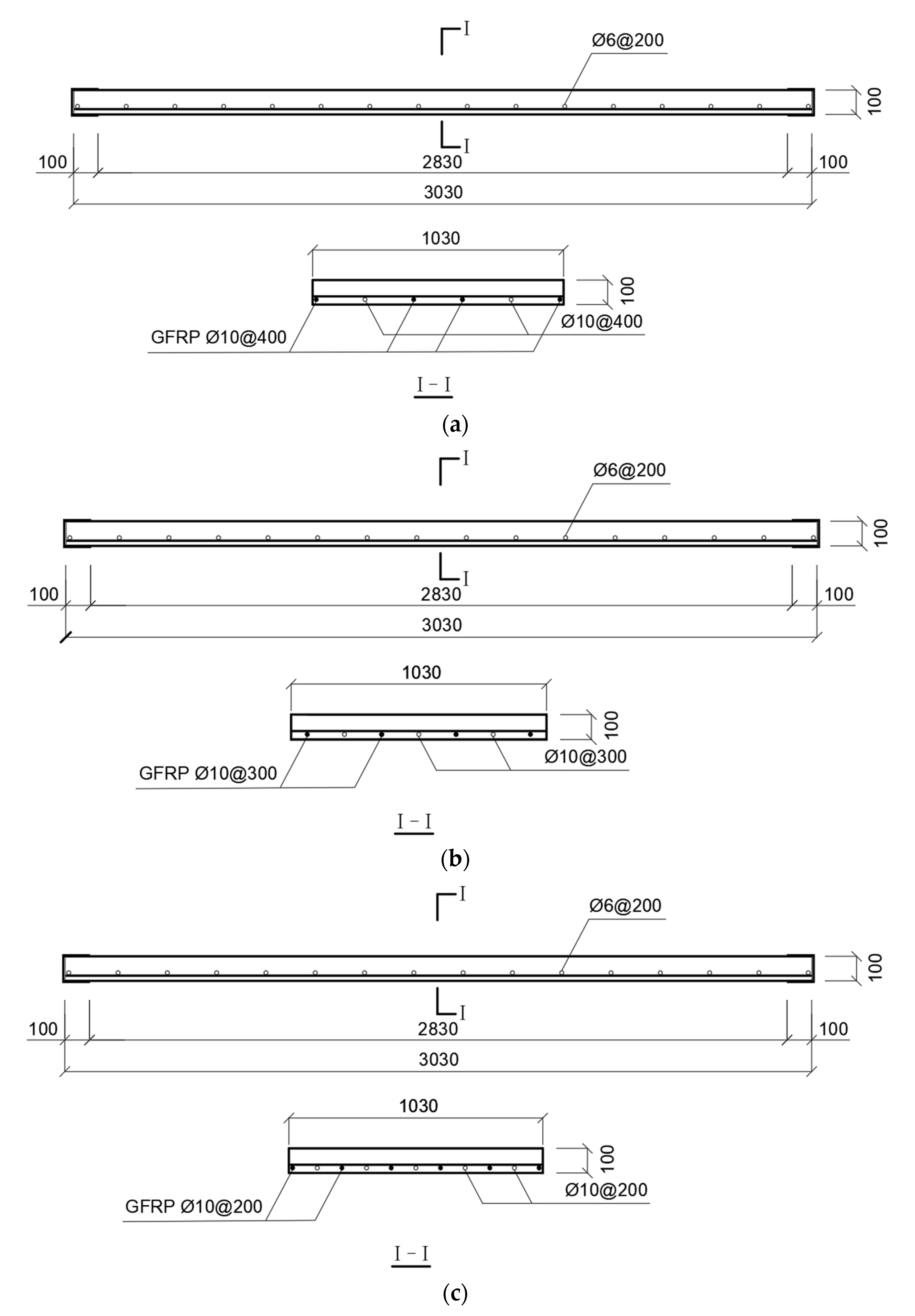
2.1. Experimental Specimen Design

The specimens were divided into three types: hybrid-RC slab, SRC slab and GFRP-reinforced concrete (GRC) slab. The slab dimensions were 3030 mm × 1030 mm × 100 mm. The compressive strength of the concrete was 30 MPa. The thickness of the concrete cover was 20 mm. The concrete slabs adopted the form of single-layer reinforcement. The reinforcement of hybrid-RC slab started from the layout of GFRP bars at the edge of the slab. GFRP and steel bars were alternately arranged. The spacing of the reinforcing bar was divided into 100, 150 and 200 mm. The spacing of the SRC slab and GRC slab was only 200 mm. The reinforcement diameter was 10 mm. The distributed bars were Φ6 HRB400 and the spacing was 200 mm. The slab specimen information for the close blast is shown in Table 1, the slab specimen information for the contact blast is shown in Table 2 and the reinforcement arrangements of the hybrid-RC slabs are illustrated in Figure 1.
Due to the different elastic modulus and tensile strength of steel reinforcement and FRP reinforcement in hybrid-RC slabs, two reinforcement ratios were defined for the convenience of analysis, as shown in Formulas (1) and (2).
(1) The actual reinforcement ratio ρ, used for the comparative analysis of hybrid-RC slabs:
ρ = ρ s + ρ f
(2) Equivalent stiffness conversion reinforcement ratio ρsf,E, used for the comparative analysis of hybrid-RC slabs and SRC slabs:
ρ ( s f , E ) = ρ s + E f / E s ρ f
where ρs is the steel reinforcement ratio, ρf is the GFRP reinforcement ratio, Es is the elastic modulus of steel reinforcement and Ef is the elastic modulus of GFRP reinforcement. Specific parameters can be found in Section 2.2.
The stiffness of longitudinal reinforcement is an important factor to compare the flexural properties of SRC and hybrid-RC slabs. In the subsequent analysis, the equivalent stiffness conversion reinforcement ratio (ρsf,E) was used as the effective reinforcement ratio for the hybrid-RC slab [8,9].

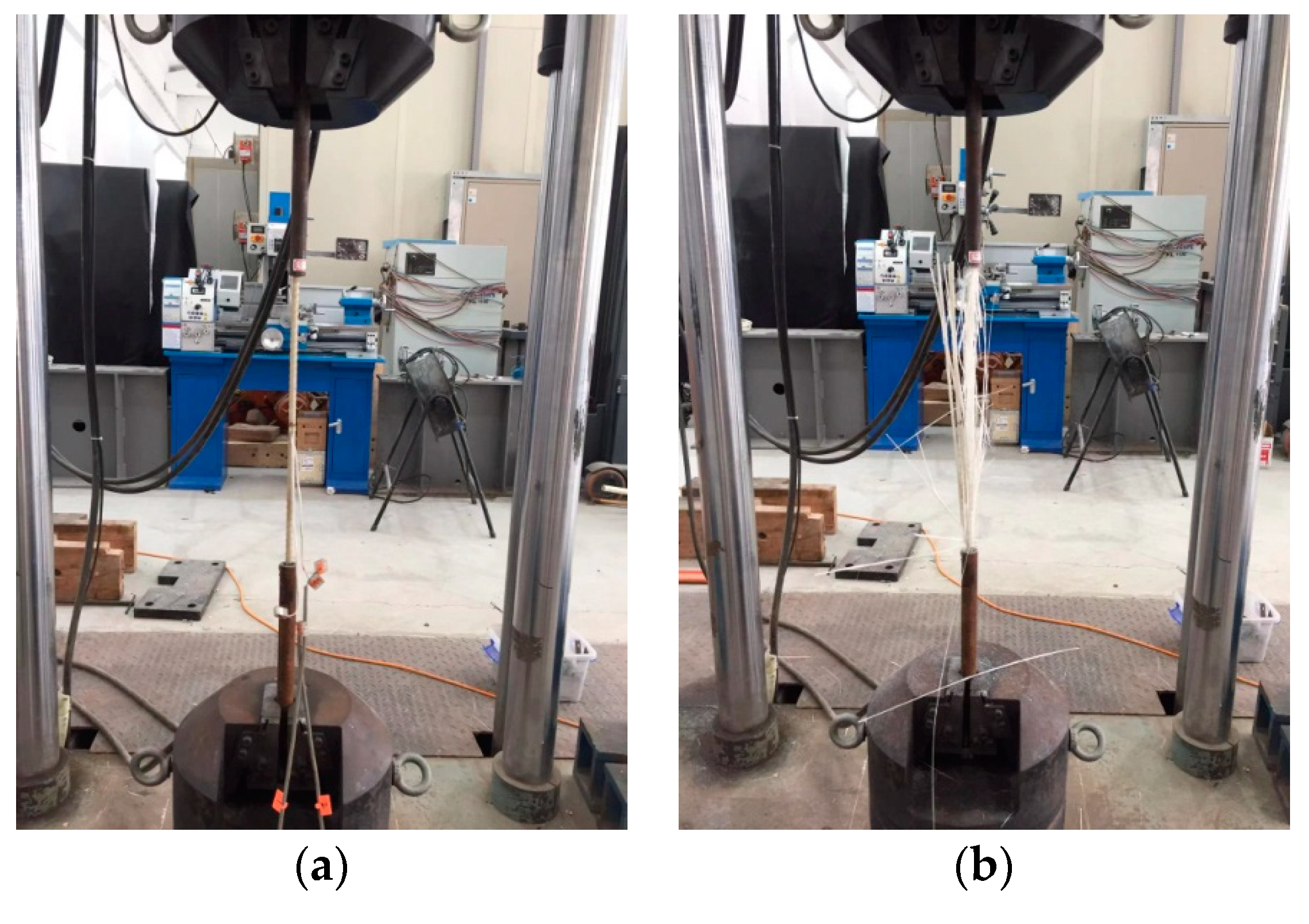
2.2. Material Properties of Experimental Specimens

HRB400E was used as steel reinforcement for the test specimens. Two pieces were randomly selected to test their mechanical properties, and the experiment was performed on a universal testing machine. The yield strength was fy = 458 MPa, the ultimate tensile strength was fu = 633 MPa, the elastic modulus was Es = 209 GPa and the yield strain was εy = 0.22%. The tensile stress–strain relationship and ultimate tensile strength of GFRP reinforcement were tested using a standard tensile experiment method. In accordance with GB/T 30022-2013 [15], five sections of GFRP bars were selected. The gauge length was 40 d (d is the diameter of the GFRP bar). The static tensile experiment adopted displacement control, and the loading speed was 2 mm/s. The tensile failure mode of GFRP reinforcement is shown in Figure 2, and the experimental results are presented in Table 3.
The tested concrete was provided by a commercial concrete mixing plant, and the specimens were poured in two batches. Three 150 × 150 × 150 mm concrete cubes were poured simultaneously in each batch. In accordance with GB/T50081-2002 [16], the compressive strength experiment was performed on six cube specimens. The test results are shown in Table 4.

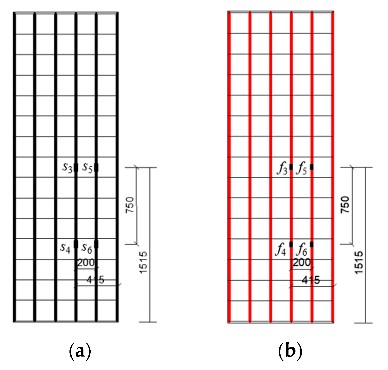
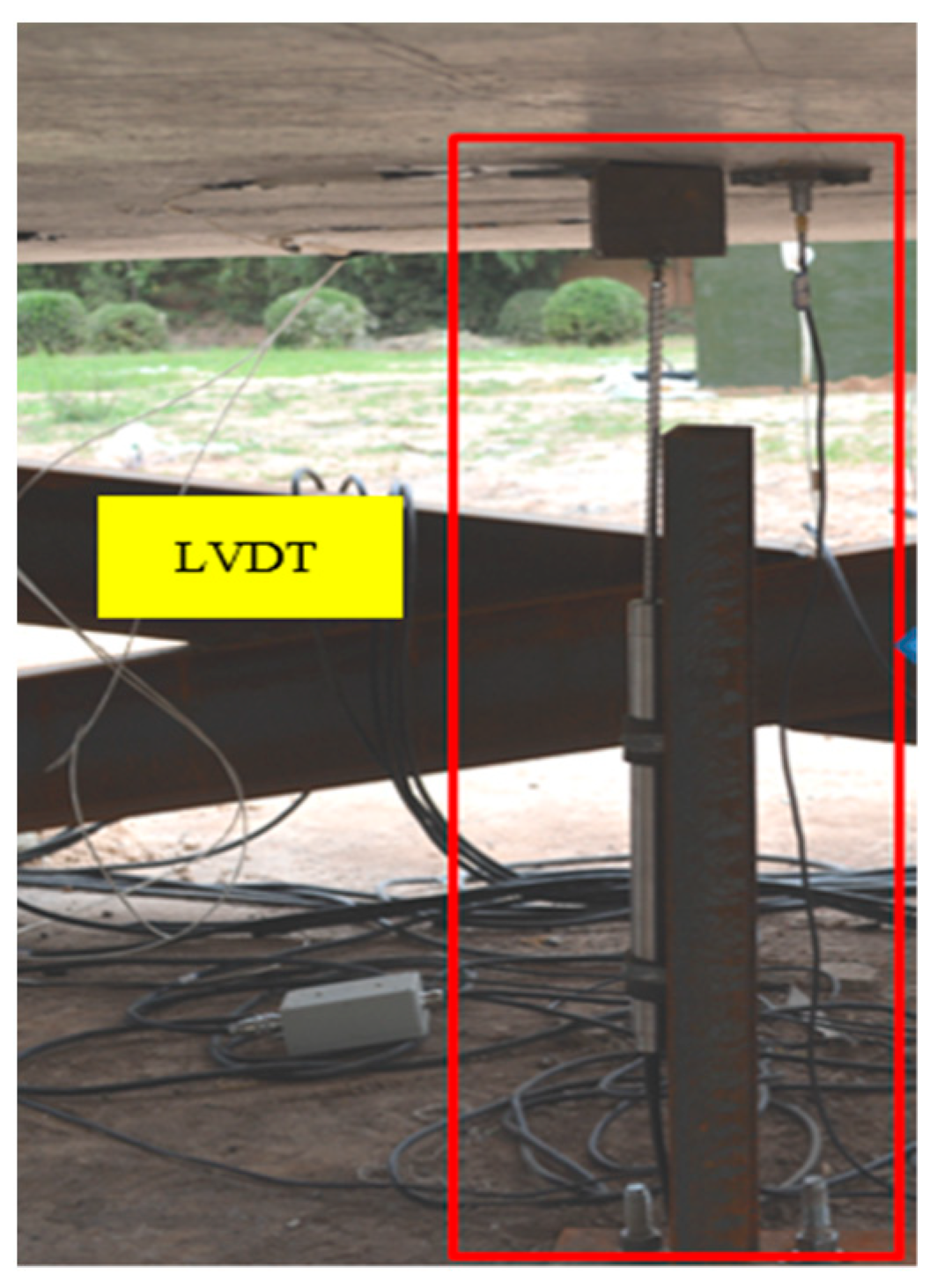
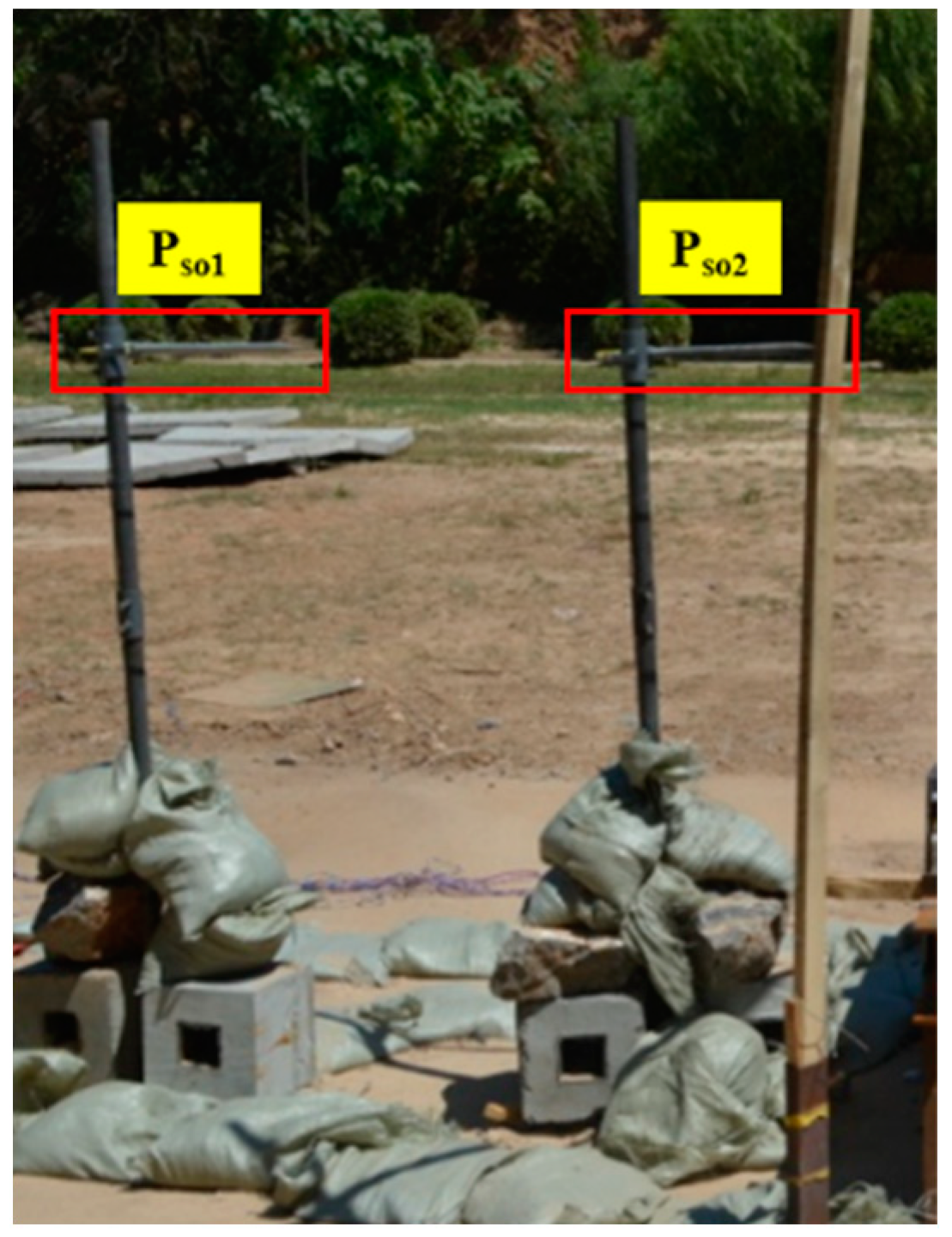
2.3. Experimental Arrangement

The test specimens were fixed on a rigid frame made of I-steel. Two clamps on each side of the slab fixed the boundary of the slab. The close blast experiment installed explosives above the center of the slab. The explosives used in the experiment were piled up with standard TNT and bound with tape before the experiment. The contact blast experiment placed explosives in the center of the slab. The explosives used in the contact blast experiment were cut from standard TNT. The shape of the standard TNT was cubic, the mass was 200 g and the dimensions were 100 × 50 × 25 mm. The explosives were detonated using a digital detonator. The experimental arrangement is shown in Figure 3.
Four strain gauges were pre-pasted onto the surface of the GFRP reinforcement and steel reinforcement at the mid-span and quarter-span of the slab. The position and number of the strain gauges on the hybrid-RC slab are shown in Figure 4. The position and number of the strain gauges on the SRC and GRC slab are shown in Figure 5. An LVDT displacement sensor was arranged at the center of the back of the concrete slab to measure the dynamic mid-span displacement, as shown in Figure 6. Two PCB pressure sensors were used to test the incident overpressure and were located 1.5 m (Pso2) and 2.5 m (Pso1) away from the explosion center, as shown in Figure 7.

2.4. Experimental Plan

For the close blast experiment, experiments under different scaled distances were performed on six hybrid-RC slabs (H4-1–H4-6) with the same design to define the damage mode of the hybrid-RC slab. Four hybrid-RC slabs with different reinforcement ratios (H5-1, H5-2, H6-1 and H6-2) were used as a control group to investigate the influence of reinforcement ratio on blast resistance. A GRC slab (G2-1) and SRC slab (S2-1) were used as a control group to investigate the blast resistance of the hybrid-RC slab.
For the contact blast experiment, experiments under different explosive mass were performed on six hybrid-RC slabs (C-H-4-1–C-H-4-6) with the same design to define the damage mode of the hybrid-RC slab. A GRC slab (C-G-2-1) and SRC slab (C-S-2-1) were used as a control group to investigate the blast resistance of hybrid-RC slab.

3. Close Blast Results

3.1. Blast Resistance of Slab with Different Reinforcement Materials

A series of blast experiments with Z = 0.684 m/kg1/3 were carried out on concrete slabs with different reinforcement materials. The blast damage results are shown in Figure 8 It could be seen that the slabs were all in bending failure mode, and cracks appeared on the top and bottom face. The cracks on the bottom face of the SRC slab radiated outward along the center of the slab, and the crack range was small but dense. The cracks on the bottom face of the hybrid-RC slab were mainly along the reinforcement arrangement direction and were accompanied by oblique cracks, with a large range of cracks that were relatively scattered. This was due to the difference in the mechanical properties between the GFRP reinforcement and steel reinforcement. Compared with the steel reinforcement, the elastic modulus of the GFRP reinforcement was low. Thus, the location stiffness of the GFRP reinforcement was small, resulting in a large range of cracks on the bottom face of the concrete slab. Therefore, the crack area on the GRC slab was the largest, followed by the hybrid-RC slab, and the crack area of the SRC slab was the smallest.
Figure 9 shows the mid-span displacement of the slab, and Table 5 shows the peak strain of the reinforcement. Comparing the concrete slabs with different reinforcement materials (G2-1, H4-2, S2-1), the elastic modulus of the GFRP reinforcement was smaller than the steel reinforcement, which made the stiffness of the concrete slab equipped with the GFRP reinforcement smaller than that of the SRC slab. Therefore, under the same blast load, the maximum displacement of the GRC slab was the largest, followed by the hybrid-RC slab and the SRC slab was the smallest. It can be seen in Figure 10 that with the increase in the effective reinforcement ratio, the maximum mid-span displacement became smaller, and the stiffness of the concrete slab with the higher effective reinforcement ratio was larger. Therefore, the concrete slab with the high effective reinforcement ratio could reduce the maximum displacement response under the blast load. The GFRP reinforcement was a linear elastic material. The maximum strain of the GFRP reinforcement in the concrete slab did not exceed the limit strain εfu = 24,000 με after the blast load and the GFRP bar was still in the elastic stage. Its linear property was less affected by the blast wave, and the capacity to dissipate energy through the vibration of the GFRP reinforcement was not affected by the blast wave. The maximum strain of the steel reinforcement in the SRC slab is εS3 = 13,623με > εy = 2200με. The steel reinforcement near the center of the SRC slab had entered the plastic stage when the mid-span displacement reached the first peak. The steel reinforcement entering the plastic stage weakened the capacity to dissipate energy through the vibration of the SRC slabs. Therefore, under the same blast load, the residual deformation of the GRC slab was the smallest, followed by the hybrid-RC slab and the SRC slab was the largest. The capacity of the concrete slab equipped with the GFRP reinforcement to recover to its original state after the blast load was better than that of the SRC slab. In addition, the GFRP reinforcement of the hybrid-RC slabs were in the elastic stage after the blast load, while the steel reinforcement entered the plastic stage. Referring to Feng's experimental data [12], the ratio of the residual bearing capacity to the original bearing capacity of the hybrid-RC slabs was predicted to be larger than that of the SRC slab after the blast load. In summary, the damage to the hybrid-RC slab was less than that to the SRC slab after the blast load. The blast resistance of the hybrid-RC slab was better than that of the SRC slab.

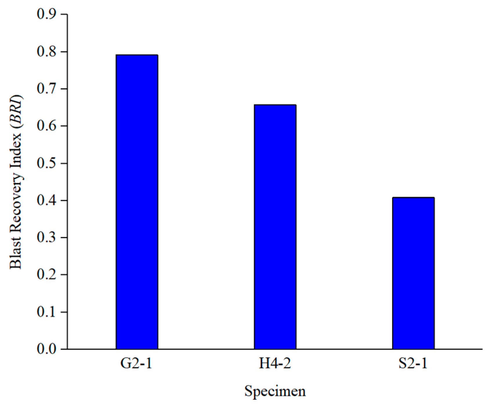
3.2. Recovery Capacity after Blast Load

The blast resistance of a structure is usually evaluated using the maximum response; however, there is little analysis on the capacity to recover to its original state after the blast load. From Figure 9b, it could be seen that the maximum displacement of the hybrid-RC slab was greater than that of the SRC slab, but the residual deformation was smaller than that of the SRC slab. Thus, there were obvious differences in the recovery capacity of the concrete slabs with different reinforcement materials after the blast load. Therefore, the Blast Recovery Index (BRI) was introduced to define the capacity of the concrete slab to recover to its original state after the blast load, which was the ratio of the recovered displacement after the blast load to the maximum displacement, as shown in the following formula:
B R I = x m a x x r e s x m a x
where xmax is the maximum displacement, mm; xres is the residual deformation, mm.
Based on the maximum displacement xmax and residual deformation xres, the BRI was easy to measure in the blast experiment and calculate in the numerical simulation. The BRI characterized the displacement recovery capacity of the structure after the blast load, and could better indicate the repairability of the structure.
Figure 10 shows the BRI of the concrete slab after the blast load. It could be seen that the BRI of the GRC slab was the highest with a value of 0.792, the BRI of the hybrid-RC slab was 0.657 and the BRI of the SRC slab was the lowest, with a value of 0.408. This was due to the linear elastic properties of the GFRP reinforcement. The capacity to dissipate energy through the vibration of the GFRP reinforcement could still play a stable role after the blast load, while the capacity to dissipate energy through the vibration of the steel reinforcement was greatly weakened after the steel reinforcement entered plasticity. Increasing the GFRP reinforcement ratio could improve the blast recovery capacity.
Although improving the GFRP reinforcement ratio could improve the blast recovery capacity after the blast load, it could not blindly increase the GFRP reinforcement ratio. This was because the elastic modulus of the GFRP reinforcement was lower than that of the steel reinforcement. The increase in the GFRP reinforcement would reduce the stiffness of the concrete slab, resulting in the increase in the maximum displacement of the concrete slab under the blast load. In the experiment, the BRI of the GRC slab was 0.792, which was much higher than 0.408 in the SRC slab. However, it could not be ignored that the maximum displacement of the GRC slab was 79 mm higher than that of the SRC slab by 49 mm. Under the same blast load, the GRC slabs would collapse before the SRC slabs when the maximum displacement response was reached. Therefore, the BRI should be increased as much as possible under the limit of the maximum displacement response. The maximum displacement of the slab was reduced by the steel reinforcement in the hybrid-RC slab, and the capacity to dissipate energy through the vibration under the blast load was improved by the GFRP reinforcement. It not only improved the ultimate resistance of the concrete slab, but also improved the service performance and repair economy of the concrete slab after the blast load. It is a structural form with excellent resistance to the blast load.
The parameters that affect the BRI value were divided into two categories: load parameters and structural parameters. For the scaled distance, We can see from Section 3.3.2 that the BRI decreased as the proportional distance decreased. The structural parameters included slab size, slab thickness, reinforcement ratio, reinforcement material, etc. For the slab size parameter, based on the explosion data of the 2030 mm × 2030 mm × 100 mm slab in reference [17], the comparison of the BRI values for differently sized slabs is shown in Figure 11. We can see from Figure 11 that the BRI value of the 3030 mm × 1030 mm × 100 mm slab with a longer span was greater than that of the 2030 mm × 2030 mm × 100 mm slab with a shorter span. This was due to the lower stiffness of the slab with long spans. Under the same explosive load, the slabs with long spans suffered significant damage, weakening their deformation recovery ability. For the slab thickness parameter, increasing the slab thickness could increase the stiffness of the slab. Referring to the influence of the slab size on the BRI, we can speculate that the BRI value will increase with the increase in the slab thickness. For the reinforcement ratio, referring to the data in Section 3.4, we observed that when the scaled distance was 0.683 m/kg1/3, the BRI values for the slabs with effective reinforcement ratios of 0.281%, 0.376% and 0.611% were 0.657, 0.672 and 0.682, respectively. The BRI increased with the increase in the effective reinforcement ratio. For the reinforcement material, Figure 10 shows the BRI of the slab with different reinforcement materials. We can see that when the scaled distance was 0.683 m/kg1/3, the BRI of the GFRP-reinforced concrete slab was 94.1% higher than that of the steel-reinforced concrete slab. The reinforcement material had a significant impact on the BRI of the slab, and the GFRP reinforcement could effectively improve the BRI value of the slab.

3.3. Damage Analysis of Hybrid-RC Slabs under Different Scaled Distances
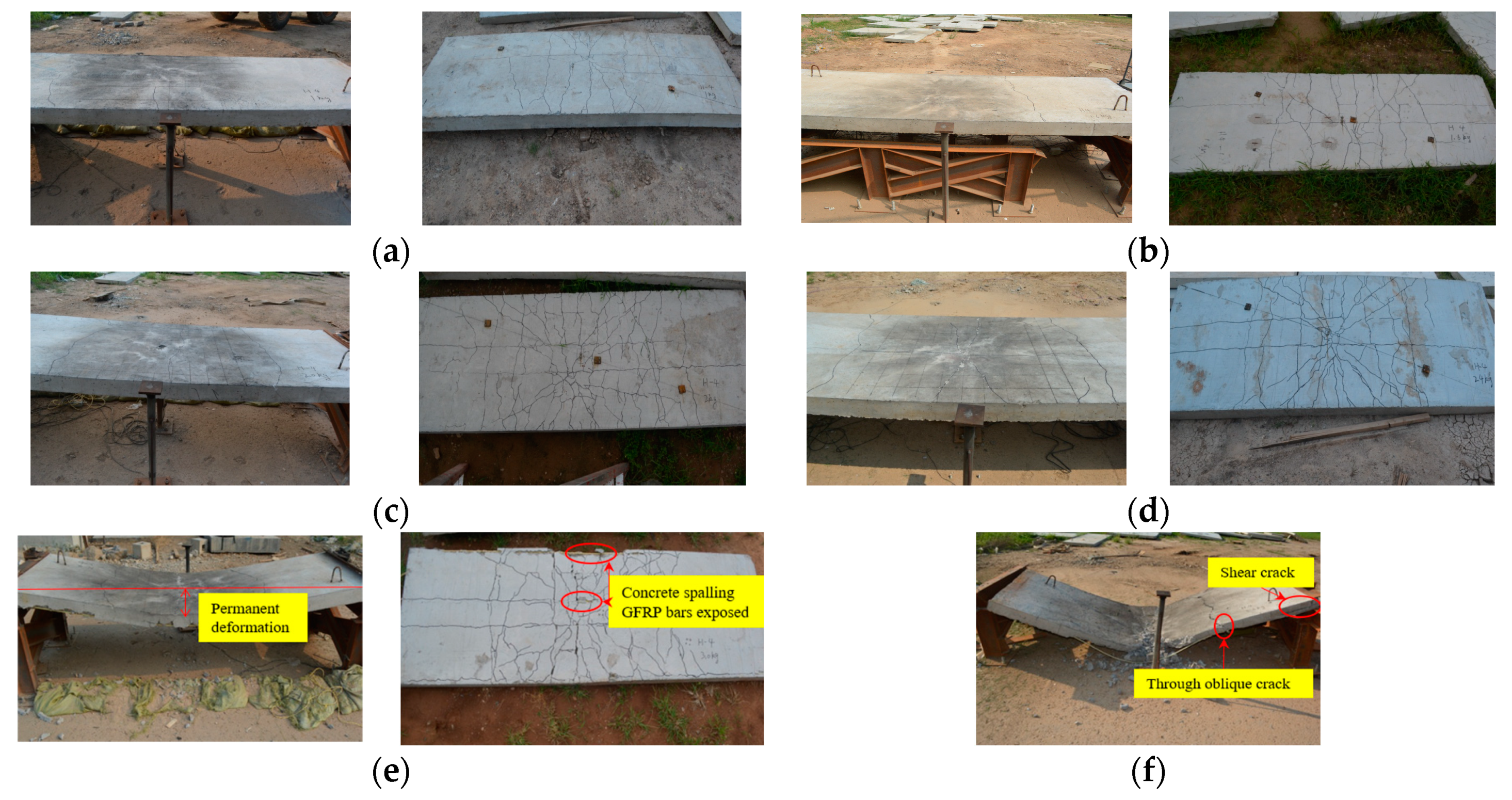
3.3.1. Damage Mode

The blast experiment results are shown in Figure 12, and the damage descriptions are presented in Table 6. Under the blast load (Z = 0.555~0.8 m/kg1/3), the blast wave caused damage on the top face of the slab, resulting in radial and circumferential cracks. The compressive stress wave propagated to the bottom face to form a strong tensile stress wave. The low tensile strength of the concrete caused cracking and spalling of the concrete on the bottom face. The slab presented flexural deformation. With the decrease in the scaled distance, the crack area of the bottom face and the permanent deformation increased. When the scaled distance was small (Z = 0.522 m/kg1/3), the flexural deformation of the slab was serious, and through oblique cracks appeared in the shear span area. Cracks also appeared at the support due to the shear force exceeding its ultimate shear stress. From Jun Li’s research [18], when the scaled distance was small, the explosion pressure was large, and the duration was short. The cracks at the support continued to develop, and shear failure occurred when the mid-span flexural deformation was not developed. Under the close blast load, the failure mode of the hybrid-RC slab exhibited overall failure. As the scaled distance decreased, the failure modes were flexural failure, flexural-shear failure and shear failure, respectively.

3.3.2. Dynamic Response Analysis

Figure 13 shows the mid-span displacement of the hybrid-RC slab. The residual displacement data in Figure 13b were obtained through on-site measurement. From Figure 14, with the scaled distance decreasing, the vibration period of the hybrid-RC slab became longer, and the time to reach the maximum displacement was longer with a greater maximum mid-span displacement of the hybrid-RC slab. The maximum displacement and residual deformation of the slab increased with the decrease in the scaled distance. The residual deformation of the slabs indicated that all of the slabs had entered the plastic deformation stage. When the scaled distance was relatively large, the maximum displacement and residual deformation changed gently with the scaled distance. However, when Z = 0.555 m/kg1/3, the residual deformation increased sharply and reached 210 mm. Combined with the failure mode of the slab when Z = 0.555 m/kg1/3 (Figure 12), the concrete on the bottom face was peeling off and the reinforcement was exposed. The slab has severe bending failure. These findings indicated that the smaller the scaled distance, the more sensitive the slab’s blast resistance was to the change in the scaled distance. As shown in Figure 14, the BRI of the hybrid-RC slab decreased with the decrease in the scaled distance. Finally, the BRI approached 0.58 because the smaller the scaled distance, the more serious the damage to the hybrid-RC slab. The proportion of the steel reinforcement entering plasticity increased, which further weakened the capacity to dissipate energy through the vibration of the concrete slab, and thus the BRI of the hybrid-RC slab decreased.

3.3.3. Damage Assessment

Selecting appropriate parameters and damage assessment criteria is very important for the damage assessment under the blast load. Scholars usually associate the assessment of the blast resistance with the maximum dynamic response of the components [19]. The damage level of structures is usually evaluated by two dimensionless parameters: the maximum ductility μm and support rotation θm. These parameters have a clear damage assessment for the maximum damage, but there is a lack of assessment for the residual damage after the blast load. The residual damage has important reference significance for the assessment of service performance and the repairability of the structures after the blast load. Based on the maximum response and residual damage, a new damage assessment criterion was proposed. The maximum support rotation θm and BRI were used to define the damage level of the hybrid-RC slab, and θr was the residual support rotation, as shown in Table 7.

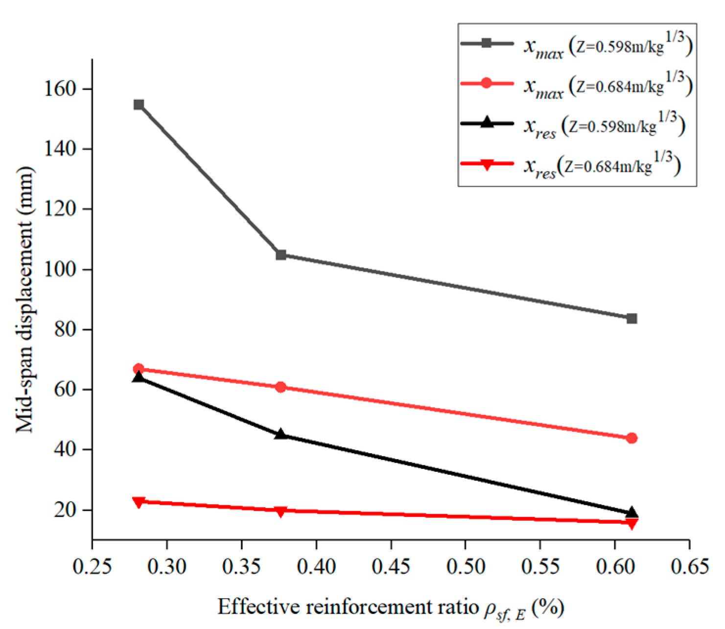
3.4. Effect of Reinforcement Ratio on Blast Resistance

The blast experiments were conducted on three hybrid-RC slabs with different reinforcement ratios. The damage patterns are shown in Figure 15. When Z = 0.684 m/kg1/3 and Z = 0.598 m/kg1/3, the concrete slabs with different reinforcement ratios presented light flexure. With the increase in the reinforcement ratio, the crack widths of the top and bottom faces became smaller. Figure 16 shows the displacement of the slabs with different reinforcement ratios. It was found that with the increase in the reinforcement ratio, the maximum displacement and residual deformation of the slab both decreased. When Z = 0.684 m/kg1/3, the maximum displacement of slab H6-1 was reduced by 34.2% compared with that of slab H4-2, and the residual deformation of slab H6-1 was reduced by 30.4% compared with that of slab H4-2. However, when Z = 0.598 m/kg1/3, the maximum displacement of slab H6-1 was reduced by 45.8% compared with that of slab H4-2, and the residual deformation of slab H6-1 was reduced by 67.8% compared with that of slab H4-2. This result showed that with the decrease in the scaled distance, an increasing reinforcement ratio was crucial to improve the blast resistance of the slab. Increasing the reinforcement ratio had an evident weakening effect on the damage to the slab.

4. Contact Blast Results

The contact blast experiment results for the hybrid-RC slab are shown in Table 8. For the three concrete slabs with different reinforcement materials, under the contact blast of a 100 g charge, the blast penetration occurred in all three reinforced concrete slabs. The diameter of the blast pit on the top and bottom were basically the same, and the penetration diameter was also basically the same. According to the analysis, the local damage phenomenon at the bottom of the concrete slab was mainly caused by a strong tensile wave, and the high-strength tensile advantage of the reinforcement could not make up for the lack of the low tensile strength of the concrete. The concrete was damaged when the reinforcement was not completely deformed. Therefore, the different reinforcement materials had little effect on the blast resistance of the concrete slabs under the contact blast. However, it can be seen from Figure 17 that the steel reinforcement entered the plastic stage, and the GFRP reinforcement was still in the elastic stage after the blast load. While the bearing capacity of the hybrid-RC concrete slab was weakened by concrete spalling, the steel reinforcement entered plasticity, which further weakened the bearing capacity. The GFRP reinforcement was less affected by the blast, and it was still in the elastic stage after the blast load. It could be inferred that the weakening degree of the bearing capacity of the hybrid-RC slab was less than that of the SRC slab after the blast load.
The damage mode of the hybrid-RC slab specimen is shown in Figure 18. The damage mode of the hybrid-RC slab under the contact blast was similar to that of the SRC slab. The failure modes of hybrid-RC slab under contact blast can be divided into four modes: (1) Blast crater, the blast caused the concrete near the center of the top face to be crushed and stripped, forming a blast pit, while the bottom face had no obvious damage, and at most a small number of radial cracks or local bulges were produced. Specimen C-H-4-1 belonged to this kind of damage mode. (2) Blast collapse, the bottom face had spalled and collapsed due to the tensile wave, resulting in a crater on the bottom face. Specimen C-H-4-2~C-H-4-5 belonged to this kind of damage mode. (3) Blast penetration, as the charges increased, the crater depth on the top and bottom face increased. There was a phenomenon that the blast pit on the top face and the bottom face were connected. Specimen C-H-4-6 belonged to this kind of damage mode. (4) Blast cut, it could be inferred that if the charge continued to increase, the concrete in the center of the slab would be cut off.

5. Conclusions

This paper mainly studied the blast resistance of a hybrid-RC slab using close blast and contact blast experiments. The blast recovery capacity of the hybrid-RC slab was stronger than that of the SRC slab after the blast load. The BRI was proposed to evaluate the blast recovery capacity of the concrete slabs. A new damage assessment criterion was proposed for the close blast. The diameter D and depth L of the top blast pit for the contact blast prediction formula were obtained through a dimensionless analysis.
(1) Under the close blast, the linear elasticity and high tensile strength of the GFRP reinforcement made the residual deformation of the hybrid-RC slab smaller than that of the SRC slab. The blast recovery capacity of the hybrid-RC slab was stronger than that of the SRC slab. The cracks on the bottom face of the hybrid-RC slab were mainly along the reinforcement arrangement direction and accompanied by oblique cracks, with a large range of cracks that were relatively scattered. The damage mode was mainly manifested as the overall bending failure.
(2) The BRI was proposed to characterize the blast recovery capacity of the concrete slabs. The hybrid-RC slab had an excellent blast recovery capacity. With the decrease in the scaled distance, the BRI of the hybrid-RC slab decreased. Based on the maximum support rotation θm and BRI, a new damage assessment criterion was proposed.
(3) With the increase in the reinforcement ratio, the maximum displacement and residual deformation of the hybrid-RC slab were reduced. Increasing the reinforcement ratio could significantly improve the blast resistance of the hybrid-RC slab.
(4) Under the contact blast, the hybrid-RC slab showed local damage. There was little difference between the local damage size of the hybrid-RC slab and the SRC slab. However, after the blast load, the steel reinforcement entered the plastic stage, and the GFRP reinforcement was still in the elastic stage. The weakening degree of the bearing capacity of the hybrid-RC slab was less than that of the SRC slab after the blast load.

Author Contributions

Writing—original draft preparation, Z.H.; Writing—editing, Z.H. and W.Q.; Funding acquisition, P.Z. and W.Q.; Supervision, W.Q.; Conceptualization, P.Z. All authors have read and agreed to the published version of the manuscript.

Funding

The funder is Wenjun Qu. This research was funded by the “Study on the Performance of Durable Sections of Concrete Structures” from the National Natural Science Foundation of China, grant number 51678430.

Data Availability Statement

The data that support the findings of this study are available on request from the corresponding author Wenjun Qu, upon reasonable request.

Conflicts of Interest

This is the first submission of this manuscript and no parts of this manuscript are being considered for publication elsewhere. No conflict of interest exists in the submission of this manuscript, and the manuscript is approved by all authors for publication. I would like to declare on behalf of my co-authors that the work described was original research that has not been published previously, and is not under consideration for publication elsewhere, in whole or in part. All of the authors listed have approved the manuscript that is enclosed.

References

  1. Ruan, X.; Lu, C.; Xu, K.; Xuan, G.; Ni, M. Flexural behavior and serviceability of concrete beams hybrid-reinforced with GFRP bars and steel bars. Compos. Struct. 2020, 235, 111772. [Google Scholar] [CrossRef]
  2. Zhou, B.; Wu, R.-Y.; Liu, Y.; Zhang, X.; Yin, S. Flexural Strength Design of Hybrid FRP-Steel Reinforced Concrete Beams. Materials 2021, 14, 6400. [Google Scholar] [CrossRef] [PubMed]
  3. Nguyen, P.D.; Dang, V.H. Analytical Identification of Failure Modes and Design-Oriented Formulations in Hybrid FRP/Steel Reinforced Concrete Beams. Int. J. Civ. Eng. 2023, 21, 727–750. [Google Scholar] [CrossRef]
  4. Zhou, B.; Wu, R.; Lu, S.; Yin, S. A general numerical model for predicting the flexural behavior of hybrid FRP-steel reinforced concrete beams. Eng. Struct. 2021, 239, 112293. [Google Scholar] [CrossRef]
  5. Qu, W.J.; Zhang, X.L.; Huang, H.Q. Flexural Behavior of Concrete Beams Reinforced with Hybrid (GFRP and Steel). Bars. J. Compos. Constr. 2009, 13, 350–359. [Google Scholar] [CrossRef]
  6. Kara, I.F.; Ashour, A.F.; Koroglu, M.A. Flexural behavior of hybrid FRP/steel reinforced concrete beams. Compos. Struct. 2015, 129, 111–121. [Google Scholar] [CrossRef]
  7. Araba, A.M.; Ashour, A.F. Flexural performance of hybrid GFRP-Steel reinforced concrete continuous beams. Compos. Part B Eng. 2018, 154, 321–336. [Google Scholar] [CrossRef]
  8. Pang, L.; Qu, W.J.; Zhu, P.; Xu, J.J. Design Propositions for Hybrid FRP-Steel Reinforced Concrete Beams. J. Compos. Constr. 2016, 20, 04015086. [Google Scholar] [CrossRef]
  9. Zhu, P.; Xu, J.J.; Qu, W.J.; Hao, H. Experimental Study of Fatigue Flexural Performance of Concrete Beams Reinforced with Hybrid GFRP and Steel Bars. J. Compos. Constr. 2017, 21, 04017036. [Google Scholar] [CrossRef]
  10. Xu, J.J.; Zhu, P.; Ma, Z.J.; Qu, W.J. Fatigue flexural analysis of concrete beams reinforced with hybrid GFRP and steel bars. Eng. Struct. 2019, 199, 109635. [Google Scholar] [CrossRef]
  11. Jacques, E.; Lloyd, A.; Imbeau, P.; Palermo, D.; Quek, J. GFRP-Retrofitted Reinforced Concrete Columns Subjected to Simulated Blast Loading. J. Struct. Eng. 2015, 141, 04015028. [Google Scholar] [CrossRef]
  12. Feng, J.; Zhou, Y.Z.; Wang, P.; Wang, B.; Zhou, J.N.; Chen, H.L.; Fan, H.L.; Jin, F.N. Experimental research on blast-resistance of one-way concrete slabs reinforced by BFRP bars under close-in explosion. Eng. Struct. 2017, 150, 550–561. [Google Scholar] [CrossRef]
  13. Johnson, J.; Xu, M.; Jacques, E. Self-Centering Hybrid GFRP-Steel Reinforced Concrete Beams for Blast Resilience. J. Struct. Eng. 2021, 147, 04021099. [Google Scholar] [CrossRef]
  14. Johnson, J.; Xu, M.; Jacques, E. Predicting the self-centering behavior of hybrid FRP-steel reinforced concrete beams under blast loading. Eng. Struct. 2021, 247, 113117. [Google Scholar] [CrossRef]
  15. GB/T 30022-2013; Test Method for Basic Mechanical Properties of Fiber Reinforced Polymer Bar. General Administration of Quality Supervision, Inspection and Quarantine of the People’s Republic of China: Beijing, China, 2013. (In Chinese)
  16. GB/T 50081-2002; Standard for Test Method of Mechanical Properties on Ordinary Concrete. China Building Industry Press: Beijing, China, 2002. (In Chinese)
  17. Han, Z.; Qu, W. Explosion resistance of hybrid GFRP-steel reinforced concrete slab[J/OL]. Acta Mater. Compos. Sin. 2023, 41, 1–11. (In Chinese) [Google Scholar] [CrossRef]
  18. Li, J.; Wu, C.Q.; Hao, H. An experimental and numerical study of reinforced ultra-high performance concrete slabs under blast loads. Mater Des. 2015, 82, 64–76. [Google Scholar] [CrossRef]
  19. Donald, D.O. Handbook for Blast-Resistant Design of Buildings; John Wiley & Sons, Inc.: Toronto, ON, Canada, 2010. [Google Scholar]
Figure 1. Hybrid-RC slab cross section and construction details (mm). (a) ρ = 0.572%, (b) ρ = 0.667%, (c) ρ = 1.048%.
Buildings 13 01058 g001
Figure 2. Tensile failure mode of GFRP reinforcement. (a) Before destruction, (b) After destruction.
Buildings 13 01058 g002
Figure 3. Experimental arrangement.
Buildings 13 01058 g003
Figure 4. Position of strain gauges for reinforcement of hybrid-RC slab (mm). (a) ρ = 0.572%, (b) ρ = 0.667%, (c) ρ = 1.048%. (Red represents GFRP reinforcement; black represents steel reinforcement).
Buildings 13 01058 g004
Figure 5. Position of strain gauges for reinforcement of SRC and GRC slab (mm). (a) SRC, (b) GRC.
Buildings 13 01058 g005
Figure 6. Displacement sensor.
Buildings 13 01058 g006
Figure 7. Pressure sensor.
Buildings 13 01058 g007
Figure 8. Blast damage on the slabs with different reinforcement materials. (a) G2-1 (ρsf,E = 0.135%), (b) H4-2 (ρsf,E = 0.281%), (c) S2-1 (ρsf,E = 0.572%).
Buildings 13 01058 g008
Figure 9. Mid-span displacement of the slab. (a) Mid-span displacement time history, (b) Comparison of mid-span displacement.
Buildings 13 01058 g009
Figure 10. BRI of the slab with different reinforcement materials.
Buildings 13 01058 g010
Figure 11. Comparison of BRI values for different size slabs.
Buildings 13 01058 g011
Figure 12. Blast damage. (a) H4-1, (b) H4-2, (c) H4-3, (d) H4-4, (e) H4-5, (f) H4-6.
Buildings 13 01058 g012
Figure 13. Mid-span displacement of the hybrid-RC slabs. (a) Mid-span displacement time history, (b) Comparison of mid-span displacement.
Buildings 13 01058 g013
Figure 14. BRI of the hybrid-RC slabs.
Buildings 13 01058 g014
Figure 15. Blast damage of the slabs with different reinforcement ratios. (a) H4-2 (ρsf,E = 0.281%), (b) H4-4 (ρsf,E = 0.281%), (c) H5-1 (ρsf,E = 0.376%), (d) H5-2 (ρsf,E = 0.376%), (e) H6-1 (ρsf,E = 0.611%), (f) H6-2 (ρsf,E = 0.611%).
Buildings 13 01058 g015
Figure 16. Displacement of the slabs with different reinforcement ratios.
Buildings 13 01058 g016
Figure 17. Reinforcement damage (C-H-5-1).
Buildings 13 01058 g017
Figure 18. Specimen damage mode. (a) Blast crater (C-H-4-1), (b) Blast collapse (C-H-4-5), (c) Blast penetration (C-H-4-6).
Buildings 13 01058 g018
Table 1. Summary of test specimens under close blast.
SpecimenReinforcement TypeReinforcement InformationExplosive Mass
(kg)
Standoff Distance
(m)
Scaled Distance
Z (m/kg1/3)
Space
(mm)
ρ
(%)
ρsf,E
(%)
H4-1GFRP–steel2000.5720.28110.80.8
H4-2GFRP–steel2000.5720.2811.60.80.684
H4-3GFRP–steel2000.5720.2812.00.80.635
H4-4GFRP–steel2000.5720.2812.40.80.598
H4-5GFRP–steel2000.5720.2813.00.80.555
H4-6GFRP–steel2000.5720.2813.60.80.522
H5-1GFRP–steel1500.6670.3761.60.80.684
H5-2GFRP–steel1500.6670.3762.40.80.598
H6-1GFRP–steel1001.0480.6111.60.80.684
H6-2GFRP–steel1001.0480.6112.40.80.598
G2-1GFRP2000.5720.1351.60.80.684
S2-1Steel2000.5720.5721.60.80.684
Table 2. Summary of test specimens under contact blast.
SpecimenReinforcement TypeReinforcement InformationExplosive Mass
(g)
Space
(mm)
ρ
(%)
ρsf,E
(%)
C-H-4-1GFRP–steel2000.5720.28145
C-H-4-2GFRP–steel2000.5720.28160
C-H-4-3GFRP–steel2000.5720.28170
C-H-4-4GFRP–steel2000.5720.28180
C-H-4-5GFRP–steel2000.5720.28190
C-H-4-6GFRP–steel2000.5720.281100
C-H-5-1GFRP–steel1001.0480.611100
G-H-2-1GFRP2000.5720.135100
S-H-2-1Steel2000.5720.572100
Table 3. Tensile performance of GFRP reinforcement.
d/mmffu/MPaEf/GPaεfu/%
10 mm1060452.48
10 mm1101462.48
10 mm1042502.10
10 mm1075502.16
10 mm1071462.78
Average value107049.42.4
(ffu = the ultimate tensile strength of GFRP bars; Ef = the elastic modulus of GFRP bars; εfu = the ultimate strain of GFRP bars.).
Table 4. Experimental results for concrete compression.
SpecimenMolding Date f c u
1-12.2334.2
1-22.2335.7
1-32.2335.4
2-13.334.9
2-23.335.4
2-33.334.6
Table 5. Peak strain.
SpecimenPeak Strain (με)
εf1εf2εS1εS2
H4-2786332421613
εf3εf4εf5εf6
G2-110,210616863062809
εS3εS4εS5εS6
S2-113,623200227911288
Table 6. Blast experiment results for hybrid-RC slab.
SpecimenDamage Description
H4-1Light flexure. Annular and radial cracks appear on the top and bottom face. The maximum width of the bottom face is 0.3 m.
H4-2Light flexure. There are a few cracks on the top and bottom face. The maximum width of the bottom face is 0.5 m.
H4-3Medium flexure. The crack area on the bottom face is large, and the maximum width is 1 mm. The slab has obvious bending deformation
H4-4Medium flexure. Dense cracks radiate from the center of the slab on the bottom face with a maximum width of 4 mm.
H4-5Severe flexure. Severe cracks appear on the bottom face with a maximum crack width of 7 mm. The concrete at the center and edge of the slab is spalling, and the GFRP bars are exposed. Serious flexural deformation occurs.
H4-6Flexural–shear coupling failure. The slab is bent along the center line and cracks appear at the support. The concrete at the center of the bottom face is spalling. The GFRP bars at the center and edge of the bottom face are exposed, and the slab is seriously damaged.
Table 7. Damage assessment.
Damage LevelPerformanceDescriptionθmBRIθr
1No damageNo residual deformation; it can still be used normally without repair1
2Little damageResidual deformation appears; it can be repaired economically0.71.2°
3Medium damageSevere deformation; it can be repaired but not economical0.5
4Severe damageLosing its function and has no repair value10°
Table 8. Damage parameters under contact blast.
SpecimenTNT
(g)
Size of Top Blast Pit (cm)Size of Bottom Blast Pit (cm)Penetration Diameter
(cm)
DiameterDepthDiameterDepth
C-H-4-145132.20
C-H-4-260152.5243.40
C-H-4-370182.6294.70
C-H-4-48018.52.7325.40
C-H-4-590192.75335.60
C-H-4-610022317
C-G-1-110021327.5
C-S-1-110020317
Disclaimer/Publisher’s Note: The statements, opinions and data contained in all publications are solely those of the individual author(s) and contributor(s) and not of MDPI and/or the editor(s). MDPI and/or the editor(s) disclaim responsibility for any injury to people or property resulting from any ideas, methods, instructions or products referred to in the content.

