Article

Numerical Simulations on the Flexural Behaviours of Reinforced Concrete Girders Strengthened with Bolts

by
Hadi Naser Ghadhban Al-Maliki
1,
Ahmad Jabbar Hussain Alshimmeri
2,
Ali Al-Balhawi
1,* and
Binsheng Zhang
3,*
1
Department of Civil Engineering, Mustansiriyah University, Baghdad 10047, Iraq
2
Department of Civil Engineering, University of Baghdad, Baghdad 10070, Iraq
3
Department of Civil Engineering and Environmental Management, School of Computing, Engineering and Built Environment, Glasgow Caledonian University, Glasgow G4 0BA, UK
*
Authors to whom correspondence should be addressed.
Buildings 2023, 13(4), 1044; https://doi.org/10.3390/buildings13041044
Submission received: 18 March 2023 / Revised: 9 April 2023 / Accepted: 13 April 2023 / Published: 16 April 2023
(This article belongs to the Section Building Structures)

Abstract

:
Precast reinforced concrete (RC) girders with dapped ends are used in order to reduce the overall depths of concrete floors and bridge decking and meet architectural requirements. The structural requirements by reducing the depths of these girders result in stress concentrations within the recessed zones. Thus, girders with dapped ends require special details for the strengthening systems. The use of open transverse holes in RC sections is for the passage of various service lines such as telecommunication cables, gas lines, water pipes, electricity cables, etc. The behaviours of RC girders with dapped ends and openings strengthened by bolts subjected to two vertical concentrated loads were numerically simulated by utilising commercial finite element software ANSYS. The numerical results from the simulated models were identical and compatible with those experimental results stated in literature. The validation of the numerical results with those experimental ones was based on the statistical analysis by including the calculations of the correlation coefficients, arithmetic means, and standard deviations for all the simulated girder models in terms of loads and deflections. The obtained numerical results showed that an increase in the compressive strength of concrete by 20% would cause an increase in the loading resistance of the models by 13% and a decrease in the deflection by 21%, respectively. Also, it was indicated that the type of section, i.e., the change of the section from solid to open (with transverse openings), would decrease the resistance of the section by 8–16% and increase the deflections by 15–20%. Similarly, an increase in the number of holes would result in the decreases in the load resistance by up to 6% and the increases in the deflections by up to 24% under the same applied loads. Strengthening openings using vertical bolts has an important role in enhancing the resistance of the models by 8–20% and decreasing the deflections by 20–30%. The failure patterns were hybrid, e.g., flexure and shear, and identical with the experimental ones. Finally, the effect of using the cylindrical compressive strength of concrete as a mechanical parameter on the structural behaviours of the simulated models was investigated, which could improve the resistance loading and decrease the deflections of the models.

1. Introduction

Precast concrete members have been increasingly used since in the last century due to their well-known properties. The construction process for these types of concrete members requires a regular process for different concrete parts, e.g., assembling them in respective locations according to their structural configurations. For connecting the precast concrete members, linkage points called connections are used. These connections are important parts in the precast concrete work when it is constructed because they are used to connect the members and transfer the loads to ensure that no local failure occurs. RC beams or corbels that have dapped ends are most commonly used as connections [1]. RC beams with dapped ends provide high lateral stability and reduce the overall floor depths [2,3]. Thus, they can be used in precast RC structures including bridge girders, buildings, car parks, and precast foundation bases [4]. Also, they provide a good way to connect the columns [5]. Hence, the current investigation is intended to numerically analyse RC beams with dapped ends and assess their structural behaviours in accordance with those stated in previous experimental studies from the literature. The precast RC beams with dapped ends have reduced depths at their ends. Thus, sudden changes in the geometric longitudinal section help prevent the spreading of the internal forces. These perturbations create areas for flowing around the re-entrant corners, as well as in the nibs. These regions are called the turbulent ranges [6,7]. As stated above, the benefit of using RC inverted girders with dapped ends is to reduce the overall heights of buildings and the local depths of other members, as well as to connect the precast elements. Therefore, it is necessary to maintain this benefit by allowing different service lines to pass through, i.e., ducts, sewage pipes, and others, these members through transverse openings [8].

1.1. Literature Review

This section gathers the previous studies related to the current research. Several studies have investigated RC beams with different types of openings, e.g., longitudinal openings and web openings. Also, several influencing factors have been explored, e.g., sizes and locations of openings, flexural and shear reinforcement ratios, and strengthening of hollow beams with various ways. Many studies have assessed the performances of RC beams with various positions of cavities, e.g., longitudinal openings [5,6,7,8,9,10,11,12,13,14,15,16,17,18,19,20,21,22]. Meanwhile, other studies have investigated the performances of RC beams with openings in webs [23,24,25,26,27,28,29,30,31,32,33,34,35,36,37]. Here, some related studies are summarised below.
Mansur [23] investigated the effects of transverse openings on the structural behaviours of RC beams in the effective regions with large shear loadings and suggested guidelines for specifying the opening sizes and failure modes. Abdalla et al. [24] experimentally explored the use of fibre reinforcing polymer (FRP) sheets to reinforce the areas around web openings in RC beams which were structurally evaluated in terms of strains, deflections, cracking, and ultimate states, etc. Amiri and Begie [25] investigated the influence of openings on the structural behaviours of RC beams and the studied parameters included the opening sizes and locations, concrete strength, and the reinforcement used around the openings. They stated that the use of diagonal and vertical stirrups around the openings could enhance the structural performances of RC beams containing openings. Yang et al. [26] experimentally and numerically studied the effects of web openings on the efficiency of high strength RC deep beams, and the studied parameters included shear span/depth ratio, concrete strength, and opening sizes. Ayaç and Yilmaz [27] experimentally studied the effects of web openings on the performances of RC beams under monotonic loading, and the shapes and sizes of openings and reinforcement ratios were investigated. They found that RC beams with circular openings provided better performances than those with other opening shapes.
Amiri et al. [28] summarised the effects of openings on the structural behaviours of RC beams and regarded the beam shape, opening shape, size and location, and beam construction type as the governing parameters. Mahmoud [29] numerically studied the effects of using carbon fibre reinforcing polymers (CFRPs) on the structural behaviours of strengthened hollow RC beams, and effectively used the proposed numerical models to compare with other simulating models with different parameters. Aykac et al. [30] experimentally investigated the behaviours of RC beams with multiple web openings and the studied parameters included the opening size, the longitudinal and diagonal reinforcement ratios, etc. They indicated that RC beams with circular openings had higher loading resistances and ductility than other beams with rectangular openings, and indicated that the higher ductility of RC beams with openings was related to the presence of stirrups. Chegeni and Dalvand [31] experimentally and numerically investigated the shear failures of RC deep beams with web openings of various sizes and locations. They found that structural resistances in shear and stiffness decreased when the opening size increased. Also, the failures of the beams were found to be due to the increases in the crack widths around the corners of openings.
Jabbar et al. [32] numerically simulated the behaviours of RC beams with openings subjected to torsional, flexural, and cyclic loading. Different concrete grades were used, e.g., high-strength and ultra-high-performance concrete. They indicated that the resistances of ultra-high performance concrete beams under torsion were higher than those of high strength concrete. Hauhnar et al. [33] experimentally and numerically studied the behaviours of steel pipe reinforced RC beams with openings and indicated about 10% variations between the experimental and numerical results. Abdul-Razzaq et al. [34] experimentally and numerically investigated the behaviours of RC deep beams with web openings, and the explored parameters included the opening shapes and strengthening types. They indicated that the inclined compressive strut played an influential role in providing the structural resistances of beams and concluded that RC beams with circular openings had higher ultimate resistances than those with other opening shapes. In terms of strengthening, they also indicated that the steel plate strengthened RC beams with circular openings had higher shear resistances, and the use of stud connectors was effective in the enhanced resistances.
Hemzah et al. [35] experimentally investigated the structural performances of RC beams with openings by considering several influencing factors including the number and location of openings and the method of strengthening and indicated that the presence of openings affected the structural behaviours of RC beams with the decreased ultimate capacity. Also, the strengthened beams with carbon fibre reinforced polymers (CFRPs) had higher resistances than those of the unstrengthened beams. Jabbar et al. [36] experimentally studied the structural behaviours of RC beams with different web opening shapes under flexural loading, indicated that the used opening sizes had minor effects on the ultimate loading and deflection capacities of RC beams, and observed that RC beams with circular openings had higher shear capacities than other beams with different opening shapes. Salih et al. [37] experimentally and numerically investigated the structural behaviours of the strengthened RC beams with web openings by considering some governing factors including failure modes, ductility, stiffness, pinching width ratio and energy dissipation. They indicated that the use of CFRPs to strengthen RC beams at the locations of openings could extensively enhance the structural performances of those beams, and a good agreement between the experimental data and numerical simulation results was also observed.

1.2. Significance of the Study

The main objective of this study is to further investigate RC girders with dapped ends in precast concrete and connect different structural members together by reducing the depths at the ends. These dapped ends could be inverted or used as normal ends. There were few studies on this type of RC members and most studies in the literature dealt with regular cross-sectional girders for a variety of situations and conditions. Thus, this study is to include numerical simulations on the structural behaviours of RC girders with dapped ends using the commercial finite element software ANSYS [38] for different cases with and without transverse openings, as well as strengthening effects by using bolts. The structural behaviours were investigated by comparing the load capacities, deflections, plasticity indexes, and crack patterns with those tested results in literature [39]. Hence, hypotheses were assumed to simulate the experimental results from a previous study in the literature for verifying the validity of numerical models. Also, the studied parameters included the section types, e.g., solid or with transverse holes, as well as strengthened or unstrengthened models by bolts, number of holes, and strengthening ratios.

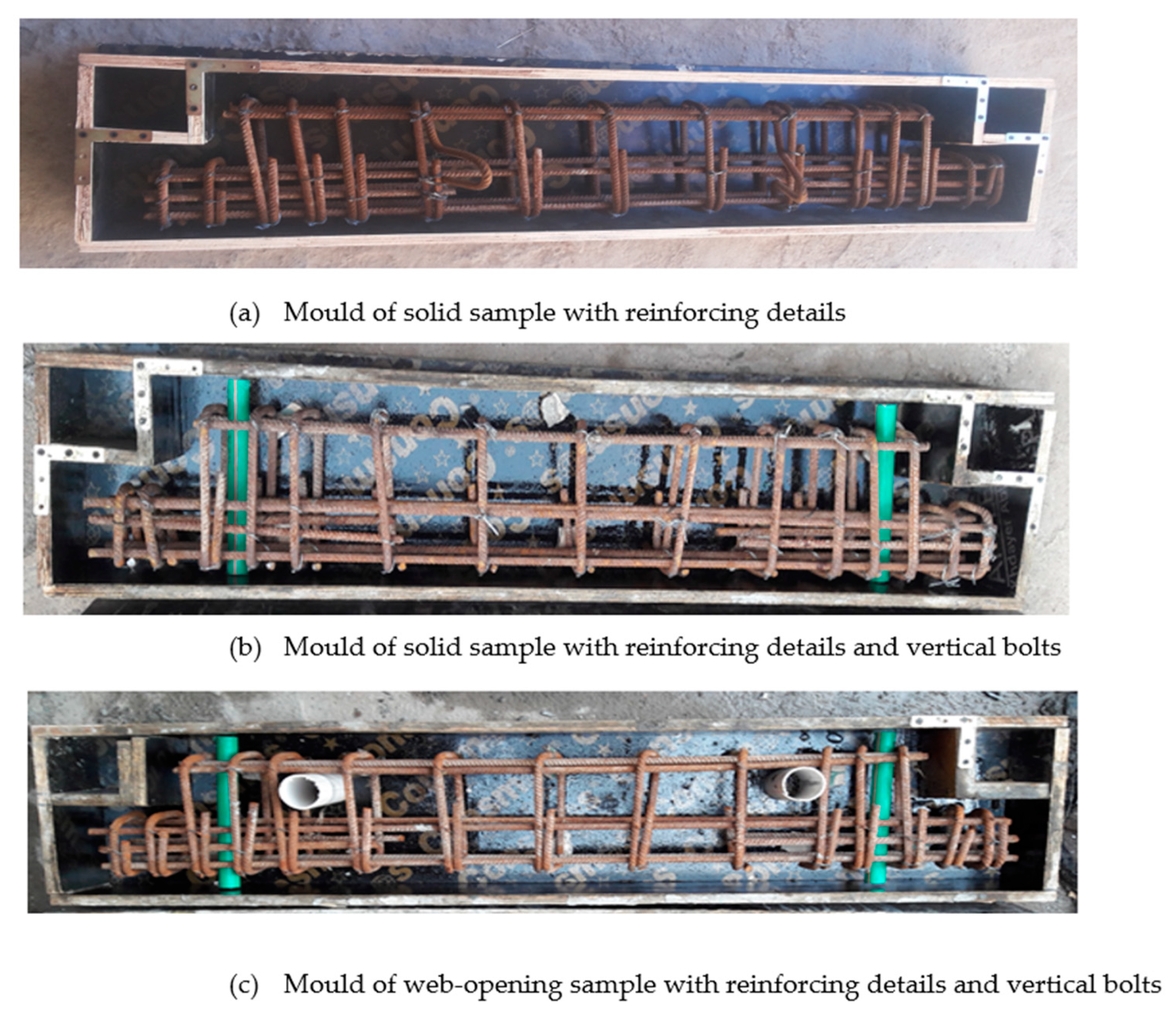
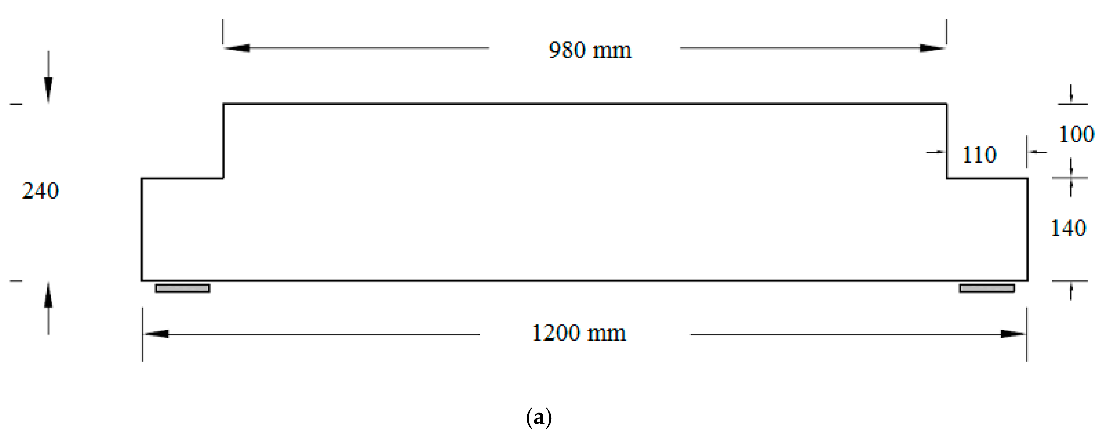
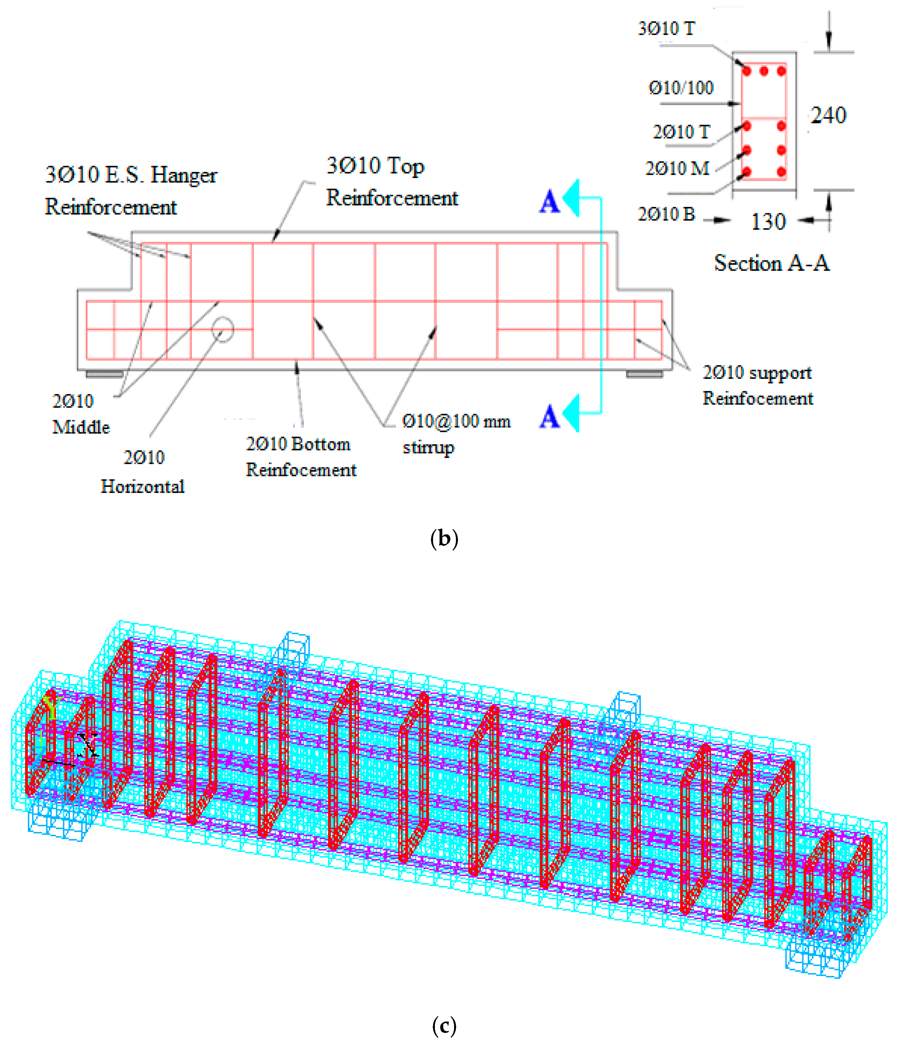
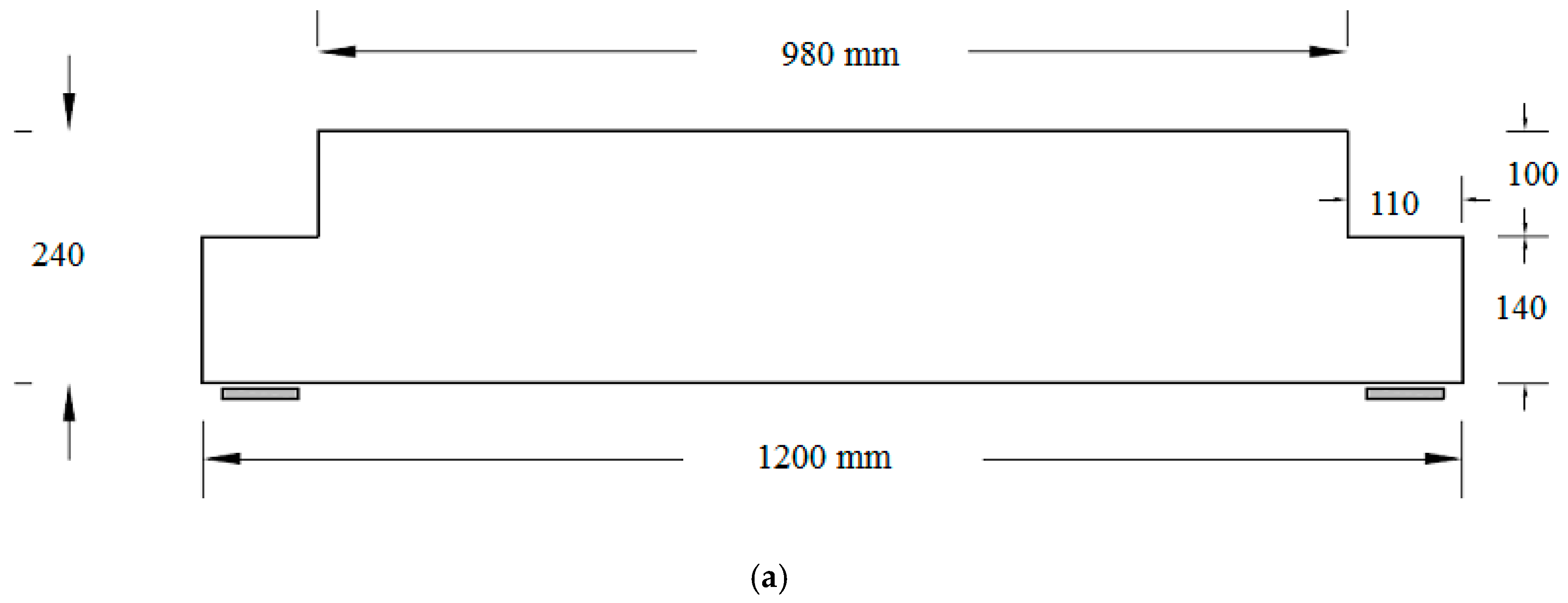
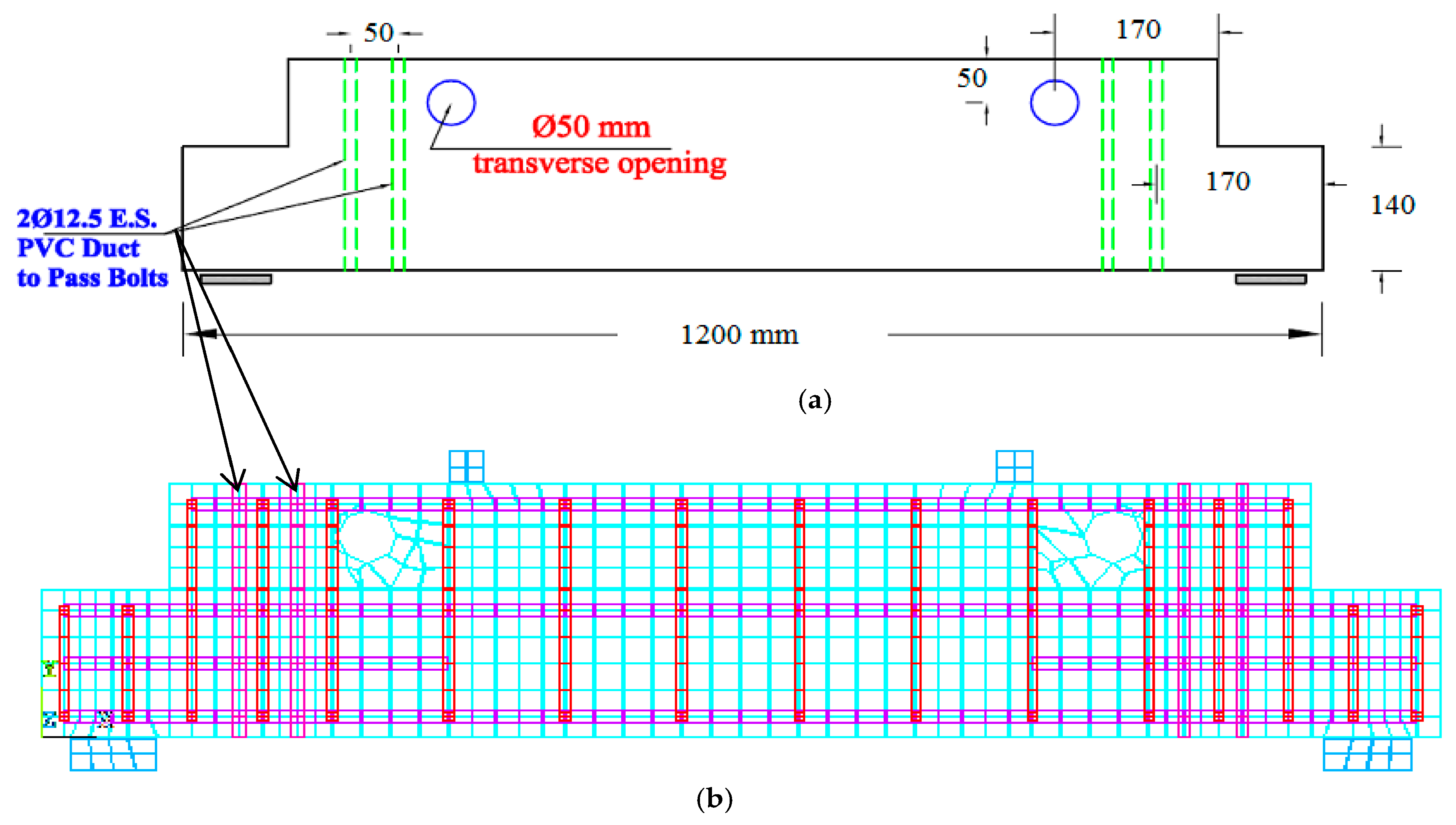
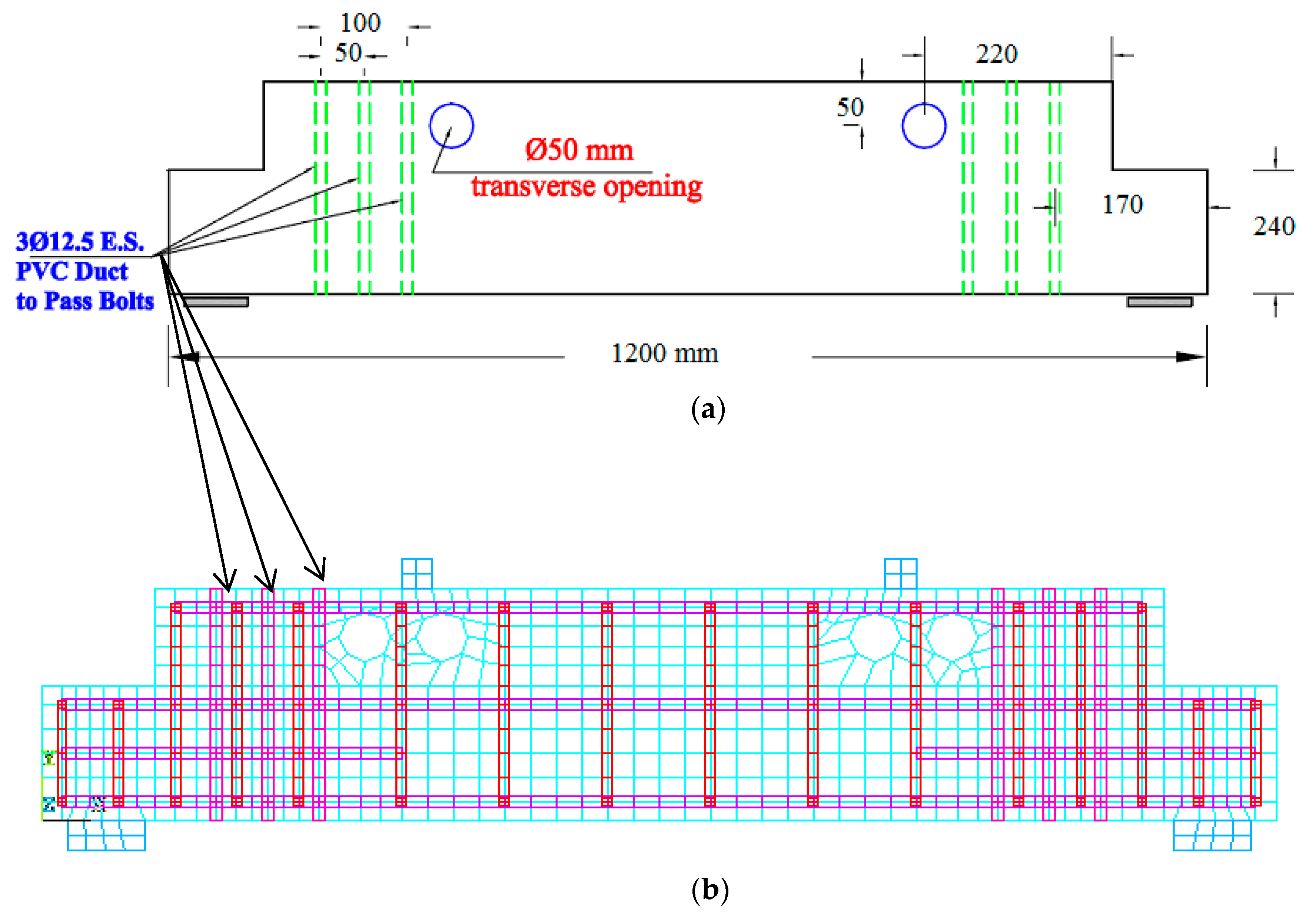
2. Numerical Models of RC Girders with Dapped Ends

The details of the numerical models and their dimensions for the numerical simulations using the ANSYS program [38] were fully based on a previous experimental study [39]. These models were designed according to the specifications of ACI-318 [40]. The type of strengthening was suggested by the common methods available for economic purposes and ease of construction by providing some models with reinforcing bars in the form of high-resistance ordinary bolts in order to strengthen and provide additional resistances, whether these RC girder models contained open recesses or not in accordance with the previous study [39]. The design details of these models could be observed in the previous experimental study [39] which included a group of seven RC girders with lengths of 1200 mm in the tensile fibres and 980 mm in the compression fibres, the reduced depths of 140 mm at the supports, the full depth of 240 mm along the longitudinal span, and the width of 130 mm. The explored parameters included the concrete compressive strength, the section types, i.e., with or without 50 mm Da. transverse holes (opening), the numbers of openings, and the strengthening way by using vertical ordinary bolts [39]. All models had the same reinforcements of 3Ø10 in the upper layers, 2Ø10 in the lower layers, 2Ø10 in the middle layers, 2Ø10 at supports and Ø10/100 for shear steel, as shown in Figure 1. The RC girder models strengthened with normal bolts were compared with those unstrengthen models, as well as those containing transverse holes (opening), in order to have a good comparison with those solid and unstrengthened models and obtain a reference model with the equivalent load resistance for the open models.

2.1. Mechanical and Material Properties

The mechanical properties of the materials that formed the concrete beam models were taken from the previous study [39]. Table 1, Table 2 and Table 3 present the properties of the concrete and reinforcing steel, as well as the strengthening bolts for the numerical RC girder models. These properties were used as the detailed input data of the material properties in the numerical simulations in the ANSYS program [38]. Figure 1, Figure 2, Figure 3, Figure 4, Figure 5, Figure 6, Figure 7 and Figure 8 illustrate the experimental and numerical details of the moulds, reinforcement rebars, hole (opening) areas, geometries of the sections, strengthening method, and locations in the models, etc. [39].

2.2. Assumptions

The basic hypotheses were adopted for the numerical simulations of the RC girder models, including concrete and reinforcing bars, which were assumed to be homogeneous and isotropic. Also, full bond between the concrete and reinforcing steel bars was assumed when defining the specific elements, i.e. when connecting them through nodes. The strengthening with bolts was also imposed so that they were completely connected, e.g., fully bonded to concrete [19] at the node points to ensure its achievement. It was assumed that the plane would remain plane when defining the strain-stress relationships of the models. The strain-stress relationship of reinforcing steel was assumed to be elastic and integrated with plasticity. Concrete had its nonlinear properties with multiple homogeneous patterns (isotropic and multilinear). When considering the mechanical properties of concrete, the points of the stress-strain relationship were regarded as acceptable within the plastic range. The numerical simulations were conducted by using ANSYS [38]. As for the reinforcing steel, it was numerically simulated using a bilinear model to represent its nonlinear behaviours, defined by the mechanical properties of the reinforcing steel, including the yielding modulus, bar area, and elastic modulus, which are available in the definition platform of ANSYS [38]. Also, the characteristics of reinforcement bolts were defined in relation to their mechanical properties which are listed in Table 3.

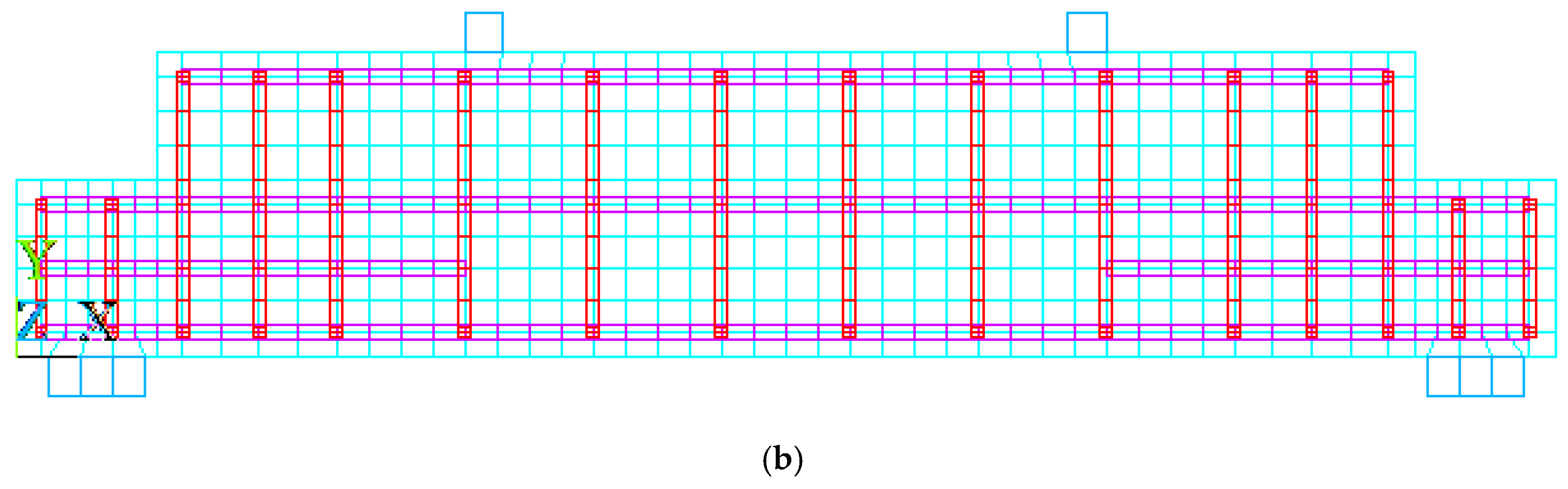
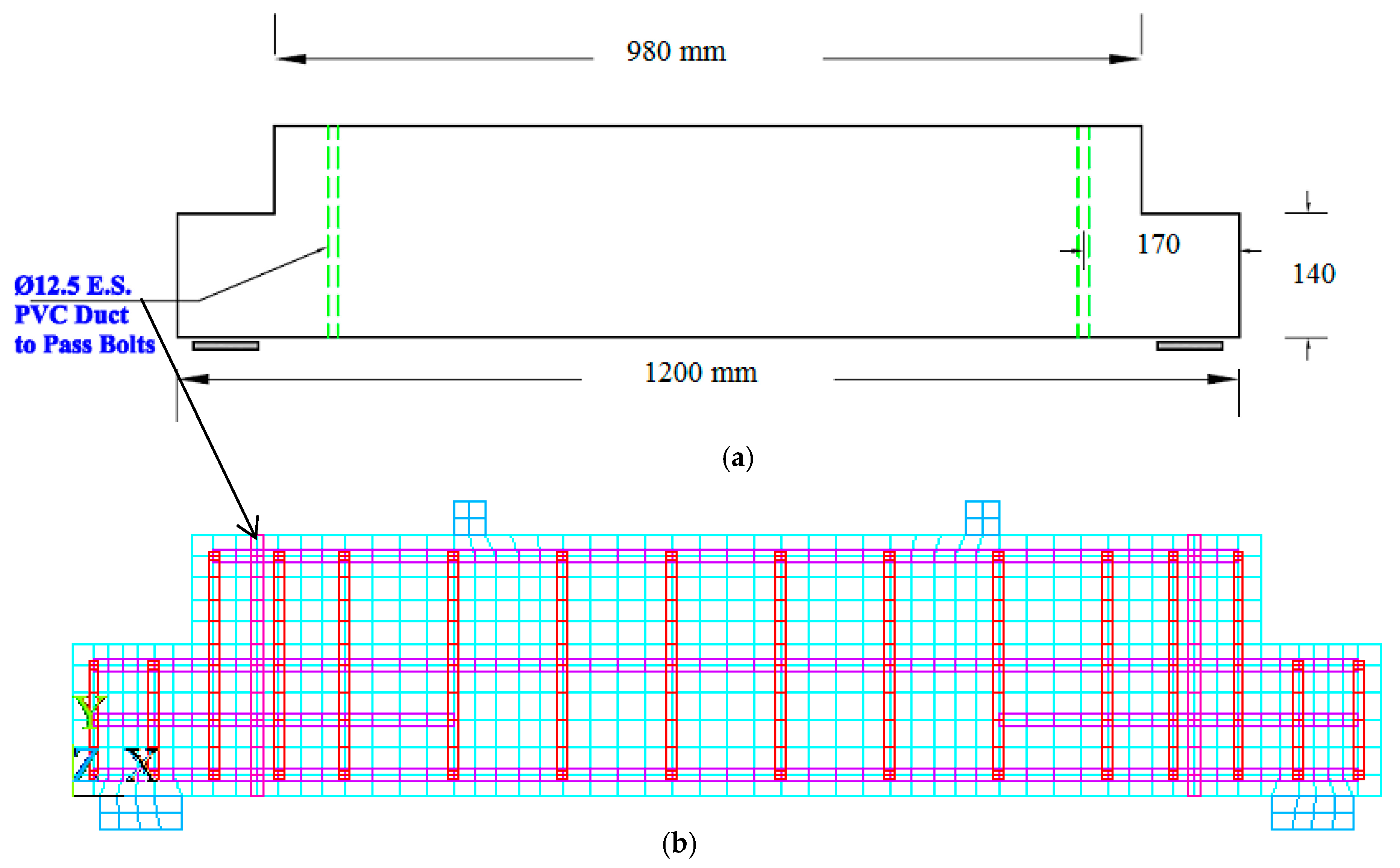
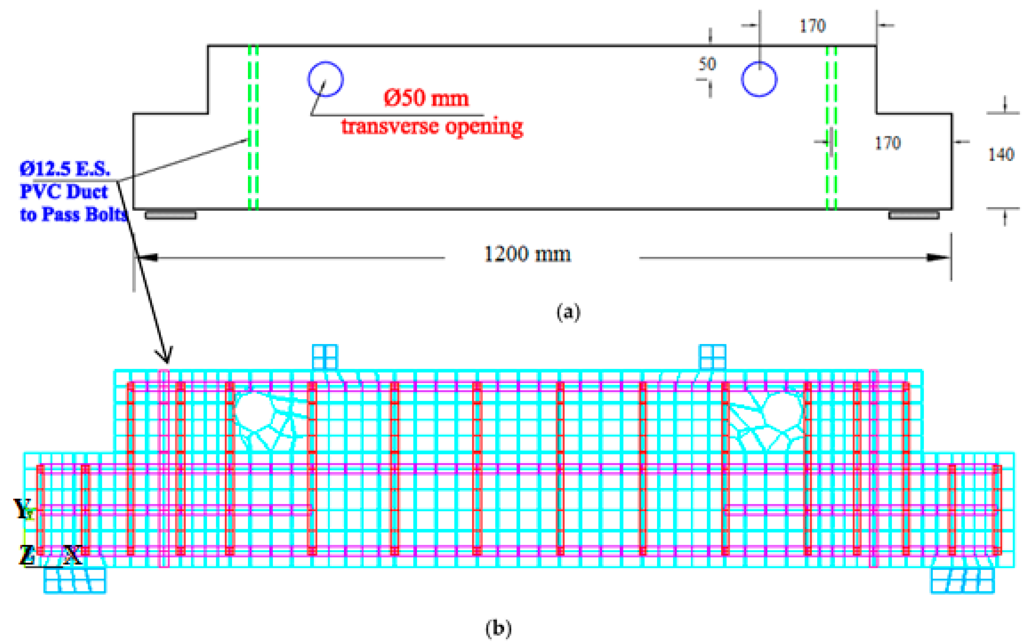
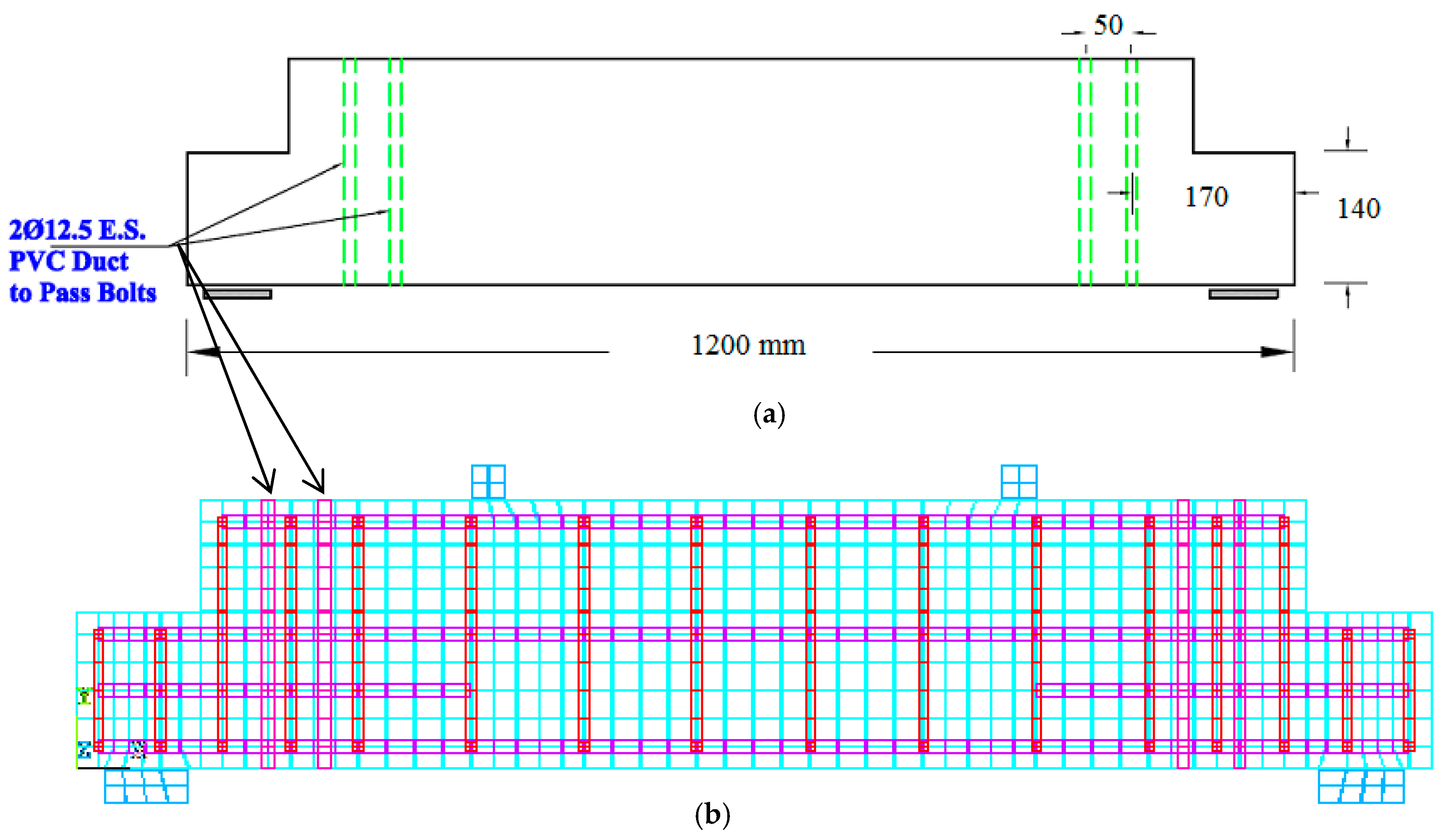
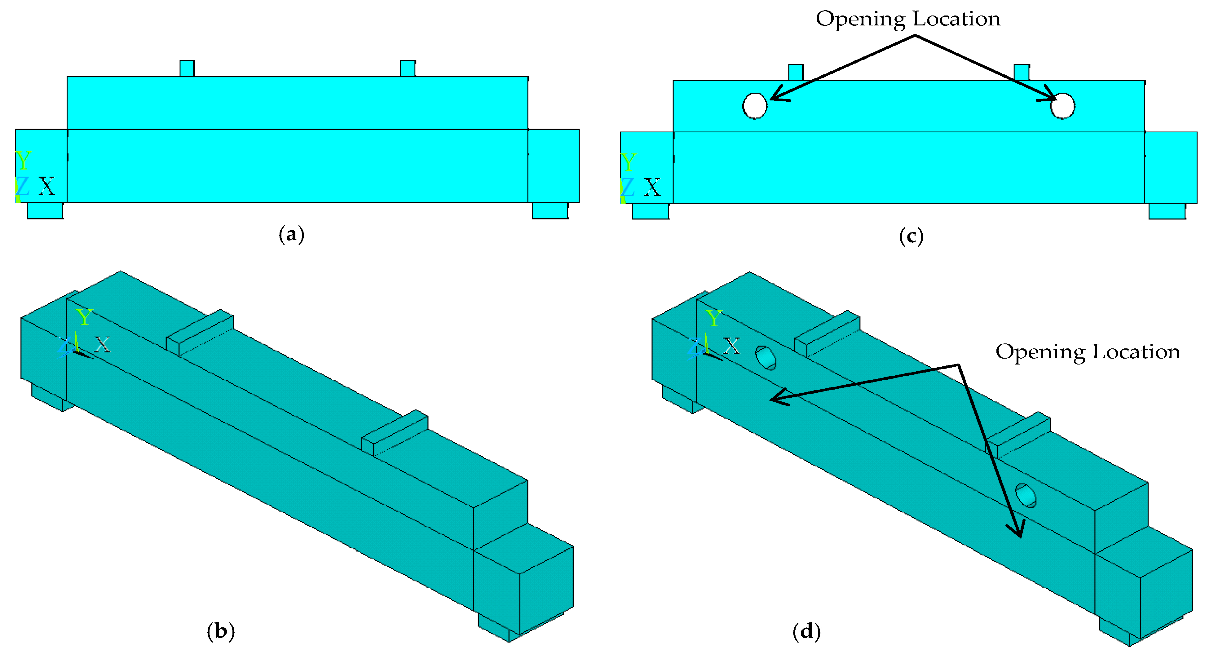
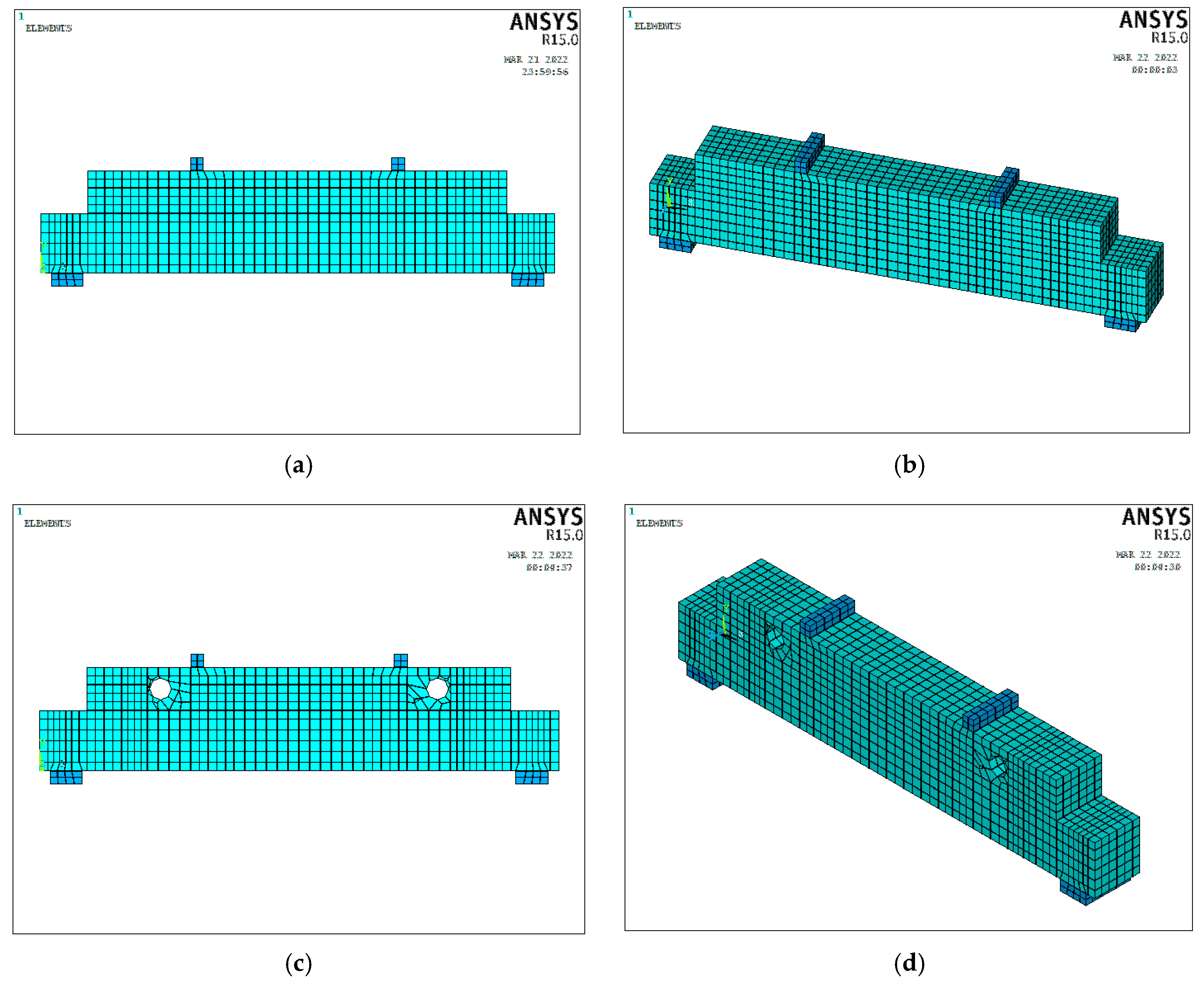
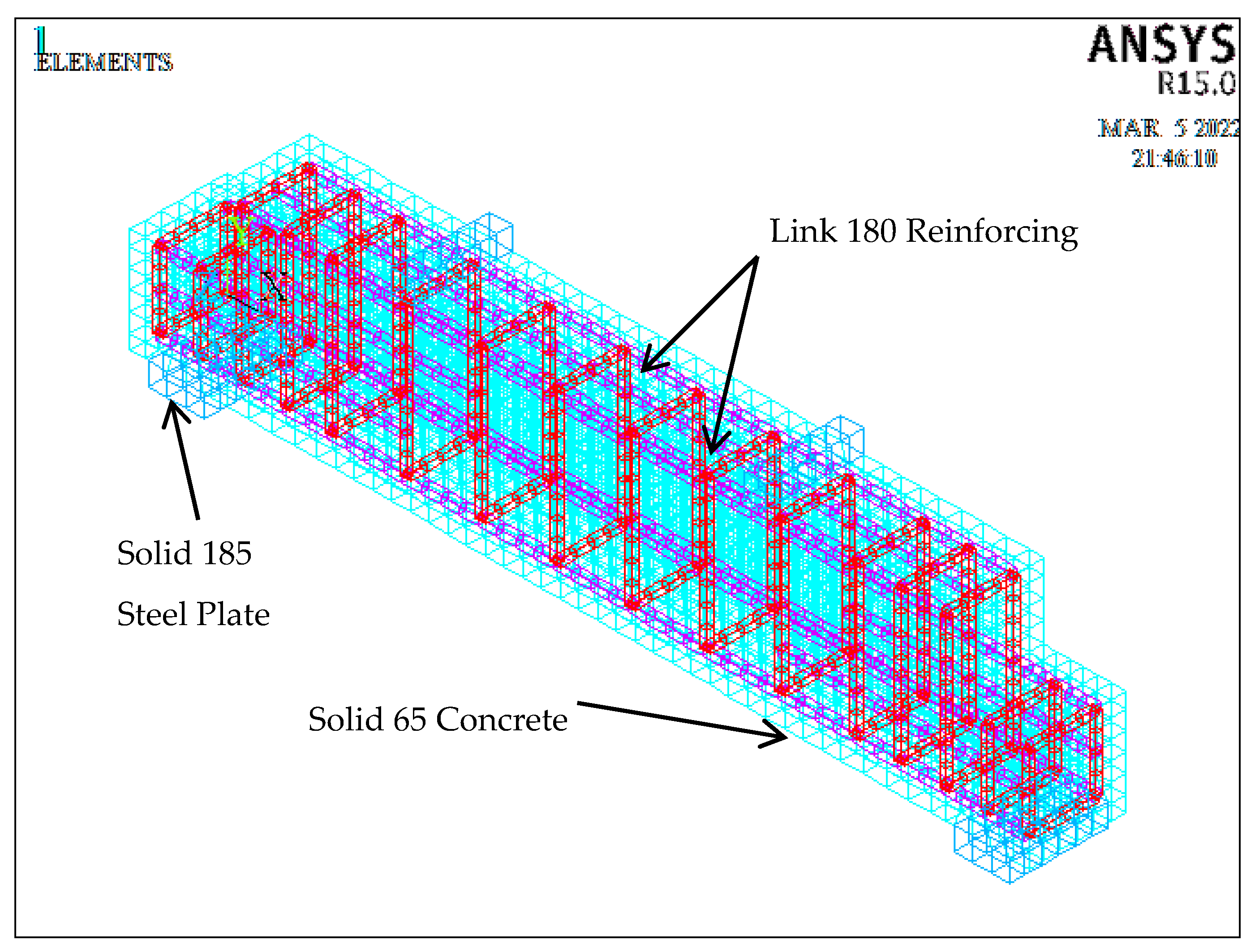
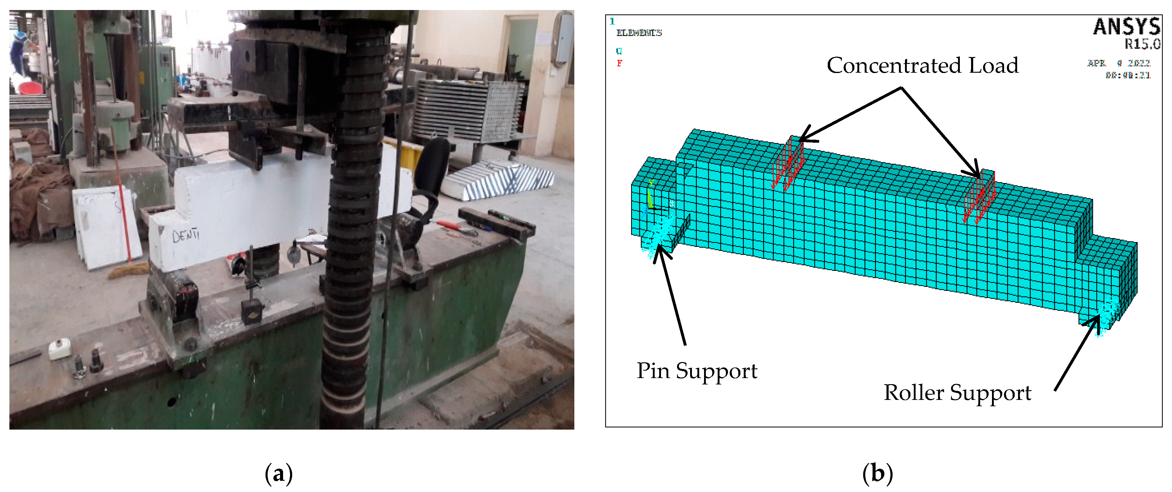
3. Finite Element Models of RC Girders with Dapped Ends

The RC girder models were simulated within a numerical analysis program to identically represent the materials depending on the experimental data stated in the previous study [39]. The characteristics of the RC girders with dapped ends were determined for a variety of cases, including loading patterns, supports and strengthening types for different models. The concrete was represented by the element solid 65, which had eight nodes with three degrees of freedom at each node. The reinforcing steel bars of various diameters, as well as the strengthening bolt rods, were represented by the connecting element link 180, which contained two nodes with three degrees of freedom at each node. For the steel plates placed at the supports and loading points, the element solid 185 was used, which had eight nodes with three degrees of freedom at each node [19,21,22].
In general, the numerical modelling of the RC girders was conducted by determining their dimensions, locations of supports, loadings, distributions of reinforcing steel bars, and hole (opening) areas. They were simulated by adopting two dimensions of the area spaces at a level, then entering the third dimension to them and determining the distribution areas of steel and supports, and then dividing a model into small elements with 25 mm in length in all directions. Hence, the cover for the experimental models was 25 mm. These elements were formed and connected by the nodes in the process of meshing for the models, i.e., all reinforcing steel bars and steel plates connected with concrete through those nodes. As a result, the interconnections of various materials were formulated through the nodes within a model by merging them together into a single node. A full bond was assumed between the simulated model components. The displacements were applied when simulating comparative models that included solid, hollow, unstrengthened and strengthened RC girders with dapped ends. Also, simulated models were modified in comparison to the previous experimental study [39]. The coefficients of open and closed concrete cracks were defined as 0.2 and 0.7, respectively. The stress-strain relationships for all materials were assumed to be completely elasticperfectly plastic [21,22]. The components of the stress-strain curves of concrete were formulated and defined during the simulation by the ANSYS program [38]. The basic hypothesis considered that the relationship was linear up to 0.85fc′, and then became plastic to the concrete strain of 0.003. Also, the self-weights of the models were neglected and considered as homogeneous with a complete full bond between all parts [21,22]. Figure 9 and Figure 10 show the basic steps of numerical modelling by the software ANSYS [38], which included the dimensions of the RC girder models, three-dimensional models, reinforcing rebars, openings (transverse holes), strengthening bolts, steel plates under the loading, and supports.
The basic step in modelling was the meshing of models by ANSYS [38], which involved dividing the model formed as volumes in three-dimensions into small-sized elements. Each element was 25 mm long in all directions. This process was also done by defining the properties and constants of individual elements to assign the specified parts. Figure 10 shows the front and three-dimensional views of the models by making meshing for the simulated models. Hence, the divisions of the adopted elements were different for individual models. Figure 11 illustrates the numerical elements that were used to represent a typical model. Figure 12 illustrates the layouts of loadings and supports for the experimental and numerical models, where the left side of the support was restricted in the horizontal and perpendicular directions to the load, which worked as a hinge support, while the right side was restricted in the vertical direction only as a roller support. The load was gradually increased and applied on the steel plates at an increment of 5 kN, through two intermediate zones within the tensile fibres of the model. The loading was continuously applied until the initial crack appeared and the failure load was reached. This numerical simulation process was completely identical with the experimental test from the previous study [39].

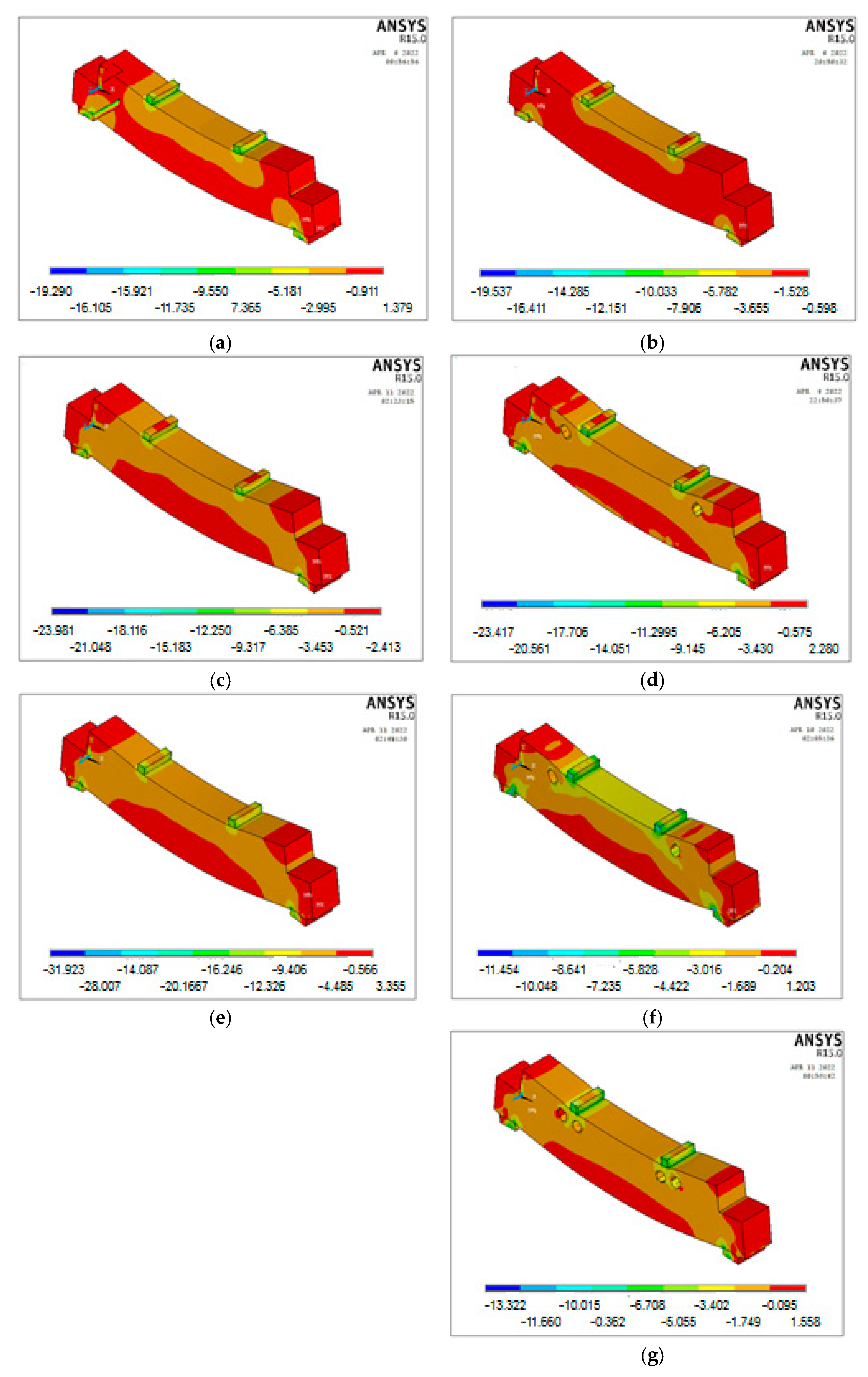
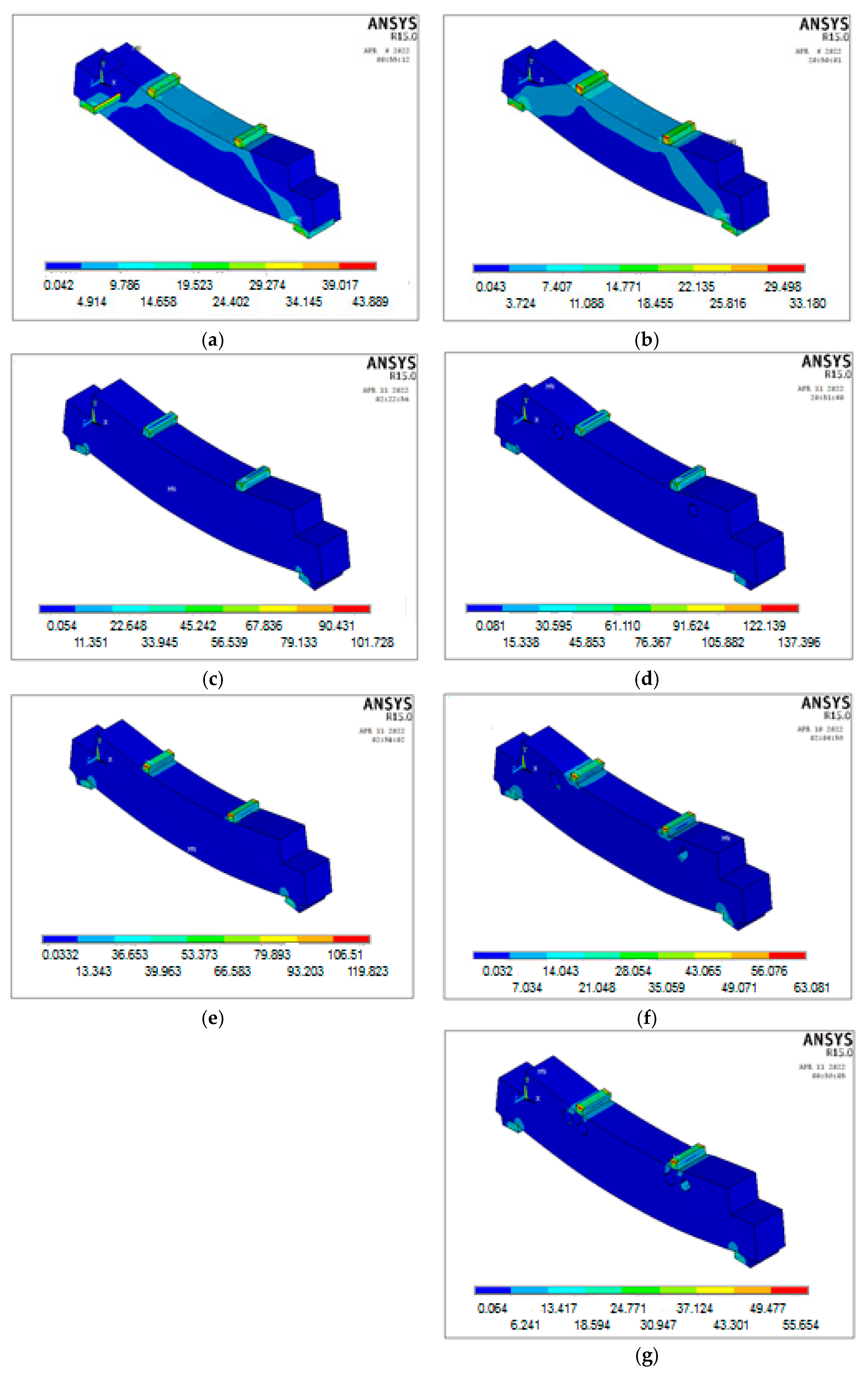
4. Results and Discussion

Seven models of RC girders with dapped ends were analysed numerically by using the ANSYS program [38]. The simulation process included the modelling of RC girders with dapped ends by defining the mechanical properties, constants, element types, applied loadings, and support conditions to match the previous experimental specimens [39]. In this section, a comparative study on the models that have been simulated with the experimental specimens will be discussed with respect to the considered parameters. The investigated parameters included the section types, i.e., solid or hollow, concrete compressive strength, strengthening methods, strengthening ratios, and numbers of holes in the numerical models. The obtained numerical results show that all the models had hybrid failure patterns, i.e., combined bending and shear failures, which were distributed in different proportions depending on the studied parameters.
Also, it can be observed that there were cracks in all models, but the percentage of cracks increased with the presence of openings (holes) in the RC girder models especially at the locations of those holes in the compression fibres of the models, which would result in the reduced resistance. Further, the models strengthened by bolts with confining the tensile and compression fibres could provide improved resistances and decrease the numbers of cracks. Similarly, the increase in the concrete strength could enhance the resistances and decrease the numbers of cracks.
The distributions of hydrostatic stresses for models can be seen in Figure 13. These stresses were generally concentrated diagonally at the points of the applied loads and supports, as well as around the openings. Also, these stresses were higher for the models with openings because they caused less rigidity by 8–15% in comparison with others under the same applied loads. It can also be noted that the increase in the concrete compressive strength could decrease the stress concentration by 18–26% [21,22]. For the strengthened models with bolts, they could provide a higher rigidity to the models in comparison to the unstrengthened ones [39] and reduce the stresses by 23–31%.
Figure 14 illustrates the distributions of von Mises stresses for all RC girder models that were analysed numerically by using the software ANSYS [38]. It can be observed that the concentrations of these stresses occurred in the regions of the applied loading and supports, as well as around the openings. This is because these stresses were distributed as a result of the loads applied to the models and in accordance with the adopted parameters [21,22]. Also, the strengthened RC girder models with bolts in the vertical direction near the locations of the openings (holes) and at the points of the applied loadings had more resistances by making a linkage of the model in an overlapping manner, i.e., the tensile and compression fibres. Thus, this could reduce the stresses and their concentrations at the points of the applied loadings and supports, as shown for models DET3 to DET7 in Figure 14.
Figure 15 illustrates the deflection contours obtained from the numerical analyses. These deflections decreased with the increase in the concrete compression strength, as a result of its contribution to the increase in the resistance and the reduction in the corresponding precipitation. It was found that these deflections also decreased for the strengthened models with bolts and hence improved the loading capacity. Also, the presence of openings (holes) in the RC girder models could reduce the load capacity and lead to an increase in the corresponding deflections. These figures also illustrate the structural behaviours of the RC girder models with dapped ends obtained from numerical analyses, which were in good agreements with the previous experimental results [39].
Figure 16 illustrates the cracking patterns, crack distributions and failure patterns of the simulated RC girder models by ANSYS [38] and their comparisons with the previous experimental test results [39]. Through the comparisons between these models, it is noted that the failure modes were hybrid, e.g., combined flexural and shear failure modes for all models in both numerical and experimental situations, where the results were generally identical. Also, it can be concluded that the types of specific elements used could provide the accurate results and predict the accurate failure patterns. These patterns were formed due to the concentrated cracks, which propagated in the regions of the applied loadings, and they diagonally extended to the locations of the supports, around the openings and in the tension fibres. It is indicated that the increase in the concrete compressive strength could reduce cracks and increase the resistance values at the same applied load. Also, these cracks were affected by the section type where the presence of openings could increase those cracks in comparison with the solid models. The increased percentage of openings could increase the percentages of cracks formed around the openings for the same reason. Finally, strengthening the models by using vertical bolts would increase the resistance and reduce cracks under the same applied loadings due to the stiffness increases of the models by confinement [41].
The loads were applied gradually at an increment of 5 kN and were continuously raised up to failure to match the experimental procedure [39]. The obtained responses of the RC girder models with dapped ends were evaluated based on their deflections at the mid-span at the distances of 500 mm from the supports as adopted in the previous study [39], as shown in Figure 12.
Comparisons of the numerical and experimental results on the cracking patterns and load-deflection curves at the mid-span of the RC girders with dapped ends are illustrated in Figure 16 and Figure 17, respectively. The investigated parameters numerically analysed by ANSYS [38] included the concrete compressive strength grades, section types (solid or with opening), numbers of openings, strengthening methods with bolts, and strengthening ratios. The deflections were evaluated on the influences of the applied loads. It was found that the increase in the concrete compressive strength by 20% could reduce the deflection by 21% and increase the resistance to the applied loadings by 13%, respectively. This is due to its contributions to the increase in the total resistance of the models through compression forces.
It is noted that the presence of openings in RC girders could weaken the resistance values of the models by 8–16% and increase the corresponding deflections by 15–20%, respectively. Similarly, an increase in the number of holes could result in a decrease in the load resistance by 6% and an increase in the deflection by 24% under the same applied load. However, strengthening the models by bolts near the locations of the openings (holes) could increase the load resistances by 8–20% and decrease the corresponding deflections by 20–30%, respectively, because the bolts served to connect the parts vertically as the confined sections.
Table 4 presents the comparisons of the numerical and experimental results with respect to the deflections of the RC girder models at the first cracking and final failure loads. Table 5 presents the details of the statistical analyses on the obtained ductility index results including the arithmetic means and standard deviations that were evaluated at the initial cracking and final failure loads, where the ductility index was defined as the ratio of the deflection at the failure load to the deflection at the initial first cracking.
It can be observed that the arithmetic mean of the relative ductility index (numerical to experimental value ratio) was 0.987, which indicated that it could be affected by other parameters such as concrete compressive strength, strengthening methods, strengthening ratios, section types (solid or with openings), and number of openings. It was found that an increase in the compressive strength of concrete would increase the load bearing capacity and accordingly decrease the deflections. Also, the strengthened models had high resistances against the applied loadings and decreased the deflections. The presence of openings (holes) in the RC girder models would reduce the resistances against the applied loadings and increase the corresponding deflections, and these behaviours followed the same trends as the increases in the percentage of holes. The results of the analyses show that the ductility index resulting from the numerical analyses were identical to the experimental results in the previous study [39] due to the types of specific elements adopted in the current numerical analyses. All the numerical studies so far indicated excellent agreements with the experimental results [39], which has provided the basis for further study on other important parameters that could affect the behaviours of the conducted numerical models. Therefore, the compressive strength of concrete was chosen as a parameter for the further analyses of several RC girders models with dapped ends. Meanwhile, other parameters will not be addressed and can be studied in the future investigations.

5. Concrete Compressive Strength as an Investigated Parameter

This study also included the analysis of models numerically based on another parameter, which had a clear effect on the structural behaviour of dapped RC girders, whether they were solid or with holes. The compressive strength of concrete was chosen as an influential factor as a result of its effective contribution to the performance evaluation of these models. Therefore, a numerical analysis was conducted by the ANSYS program [38] for 14 additional models as shown in Table 6. The compressive strengths of concrete were selected as 25, 40 and 50 MPa, respectively.
Comparisons of the numerical results with the previous experimental results [39] in terms of the maximum loads and the corresponding deflections with the concrete compressive strength are illustrated in Table 6 and Figure 18, respectively.
It is noted that increasing the concrete compressive strength would enhance the loading capacity of the RC girder models with dapped ends by 15–30% and decrease the deflections by 24–59%. The use of high-strength concrete would effectively reduce the deformations and increase the durability of the structural parts.

6. Conclusions

This numerical study was conducted on the RC girder models with dapped ends, either solid or with openings, as well as with or without strengthening by bolts under four-point bending using the commercial finite element software ANSYS [38]. The obtained results from the numerical analyses were compared with the experimental results in a previous study [39]. The main conclusions of the study are summarised as follows.
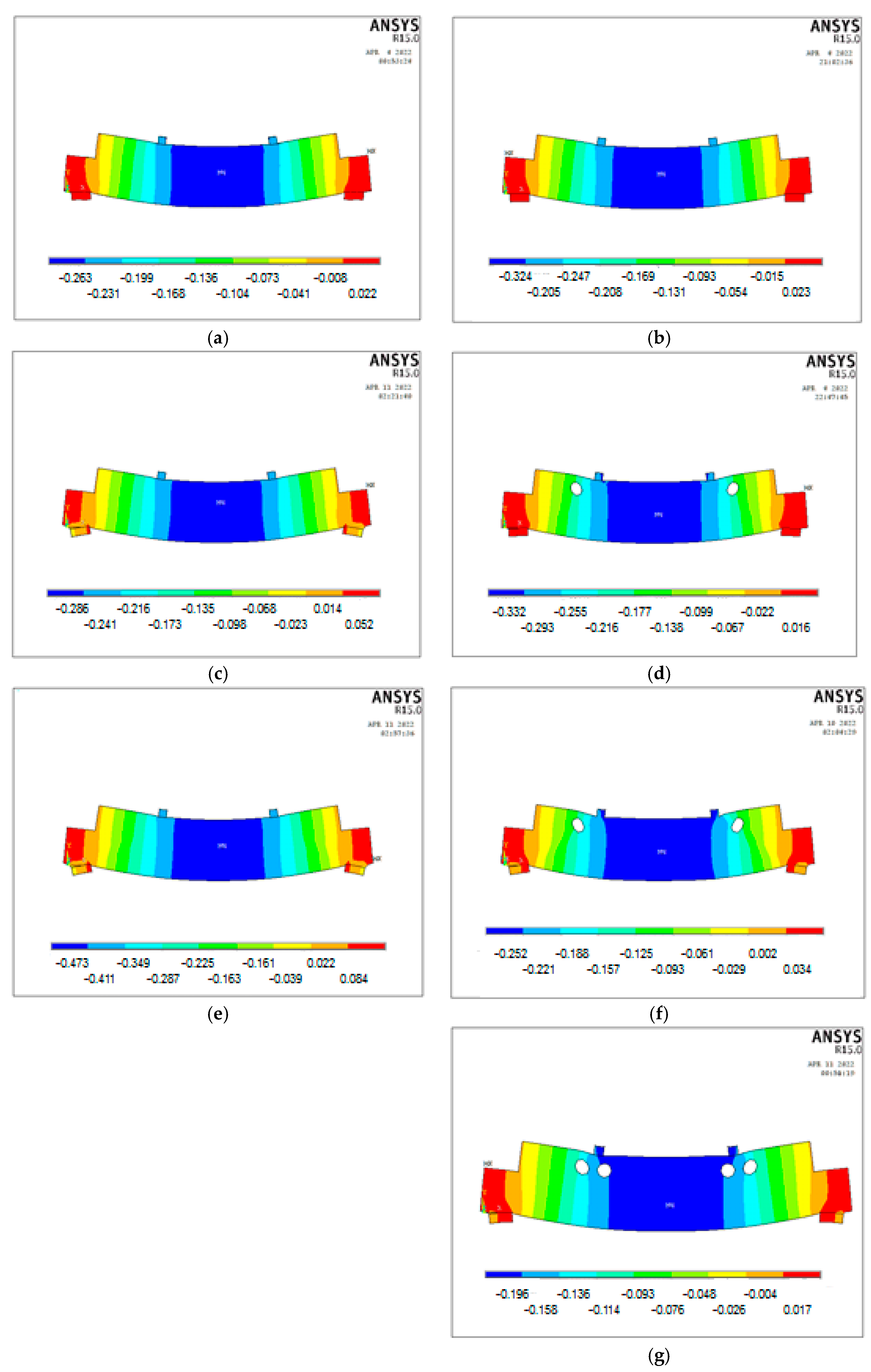
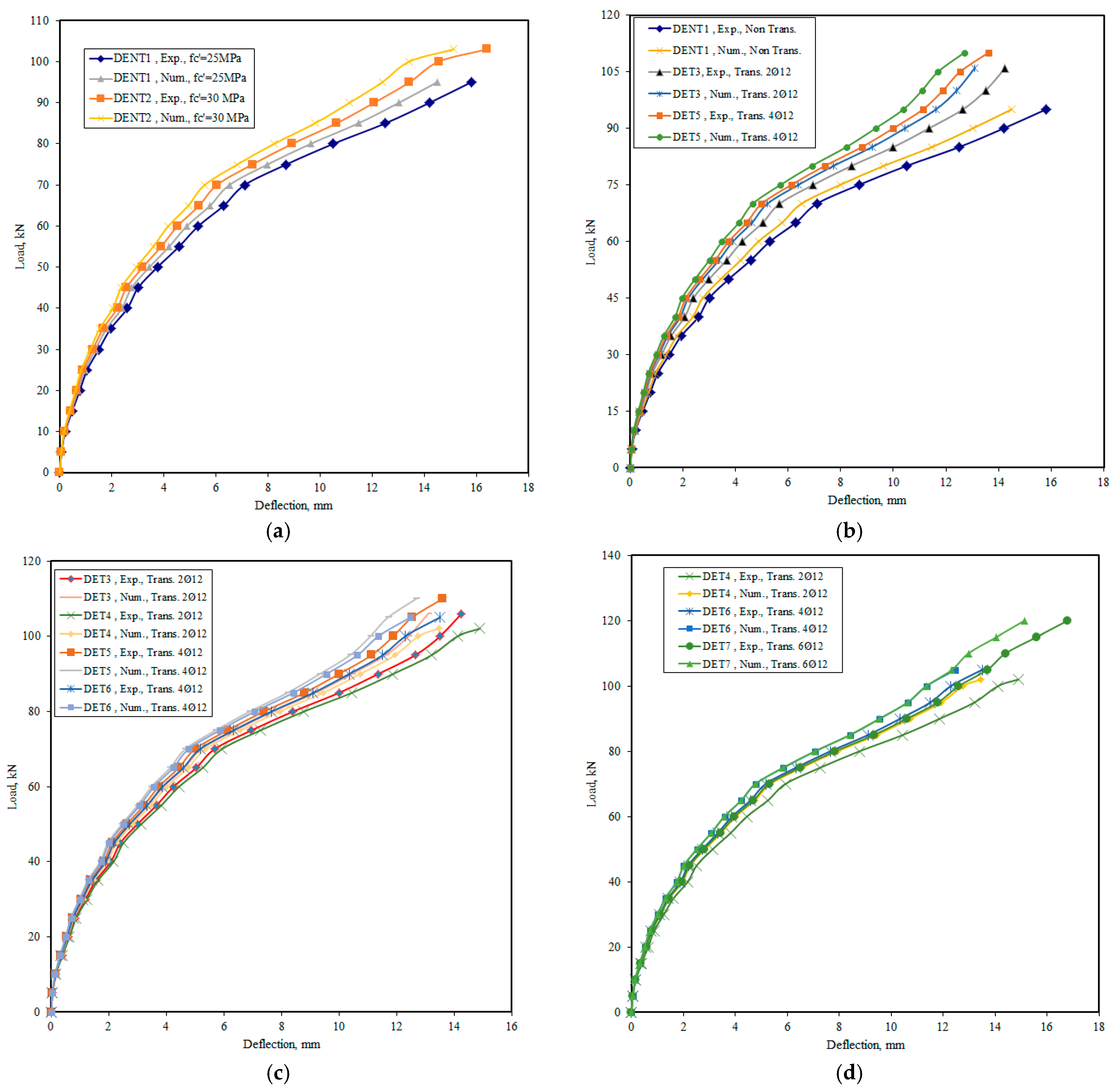
  • The obtained numerical results from the simulated models showed excellent agreements with the experimental results in the previous study.
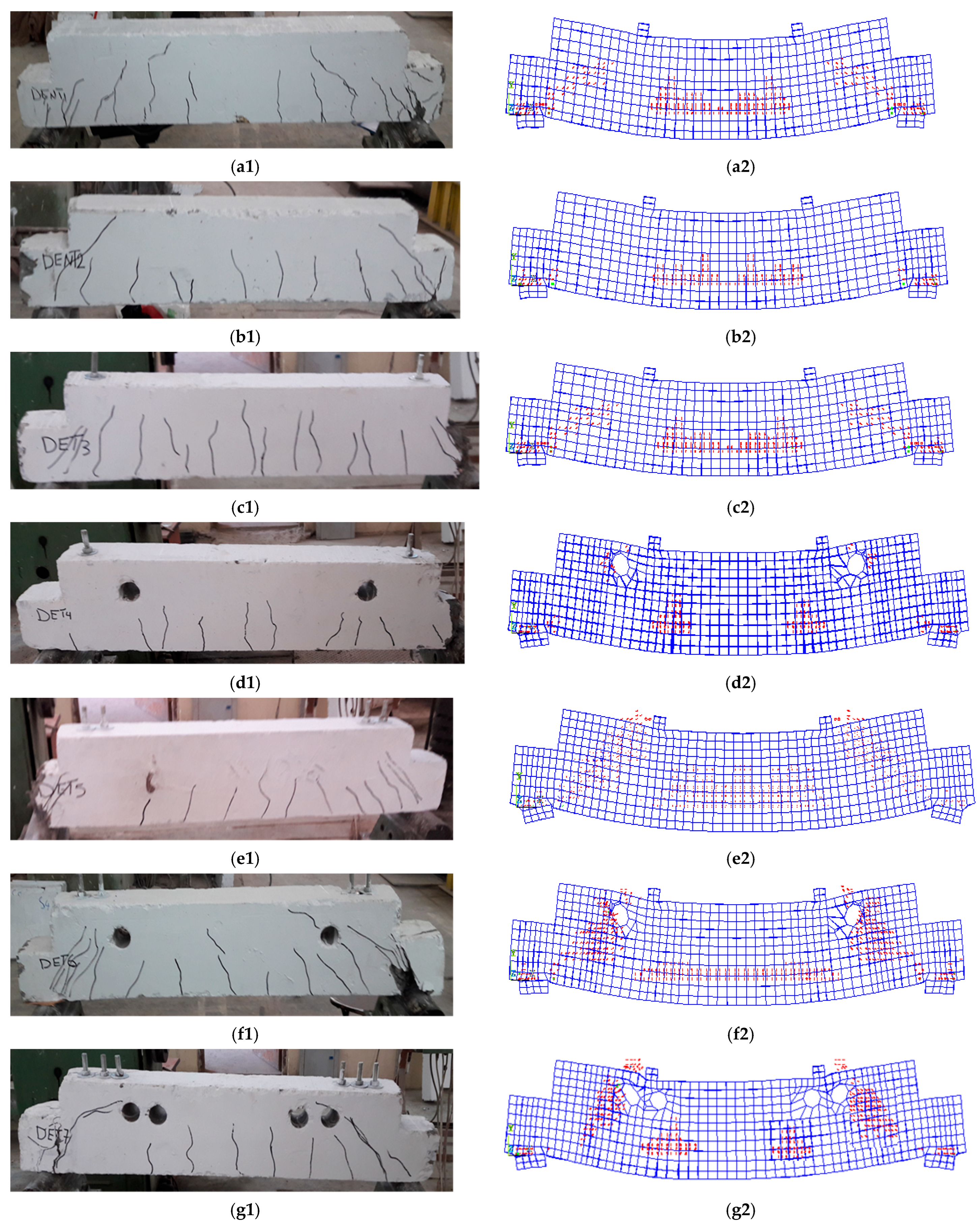
  • The results showed that the cracking patterns of the simulated RC girder models were identical to those indicated in the experimental study. The cracks were distributed in almost the same patterns for all the models, but in different proportions according to the section type, concrete strength, and strengthening type.
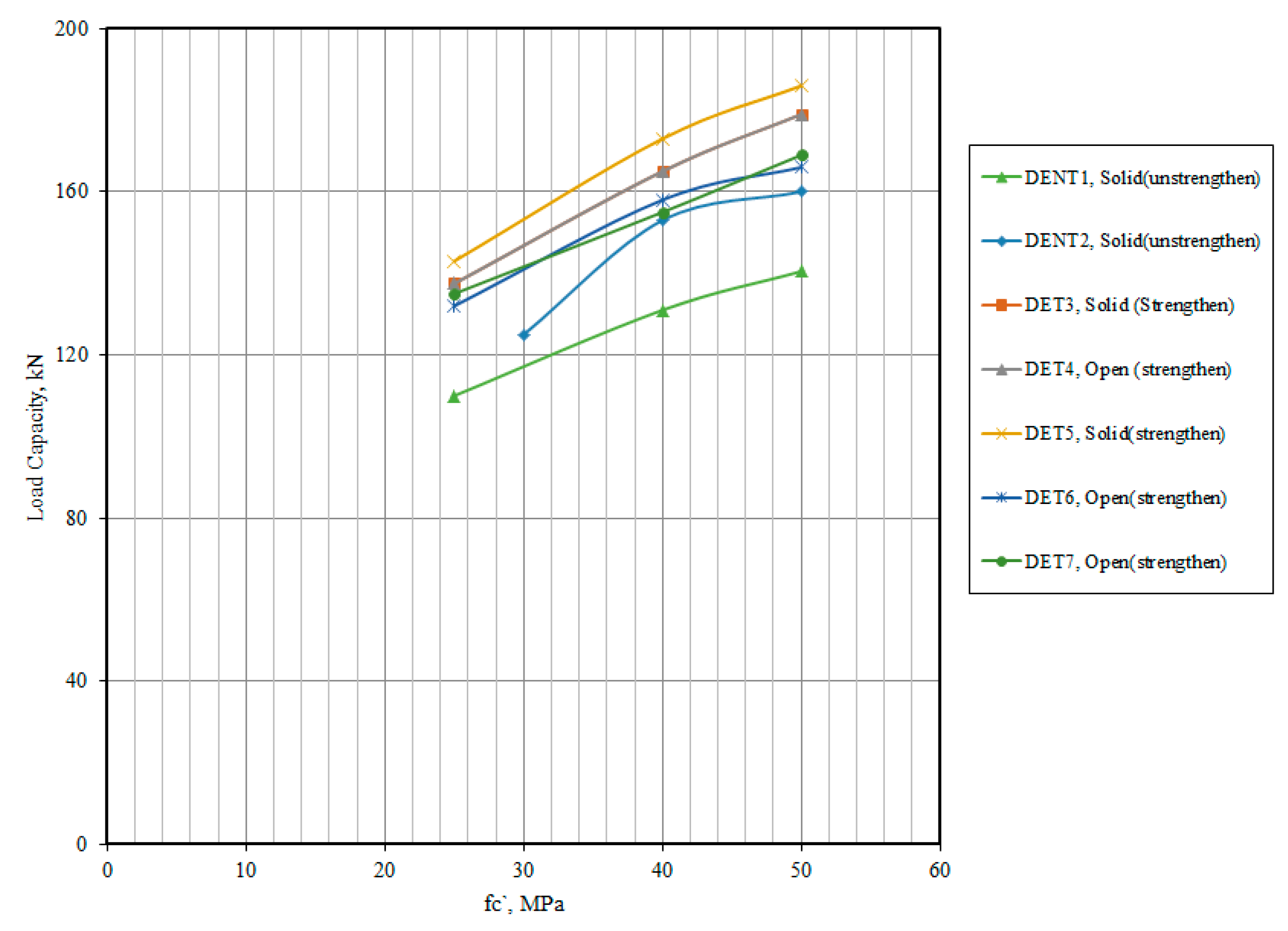
  • An increase in the compressive strength of concrete by 20% would increase the loading resistances of the RC girder models by reducing the number of cracks and decreasing the deflections by 13% and 21%, respectively.
  • The change in the section type from solid to open (with transverse openings) could decrease the resistance of the section by 8–16%, together with the increased number of cracks and the increased deflections by 15–20%.
  • An increase in the number of holes corresponded to a decrease in the resistance against the applied loading by 6% and the increase in the deflection by 24%.
  • Strengthening openings with vertical bolts could enhance the resistance of the RC girder models by 8–20% and decrease the deflections by 20–30%. Also, the strengthened RC girder models with bolts could decrease the number of propagated cracks, which were concentrated in the regions of the applied loads, supports, around openings, and in the tension fibres of the RC girder models.
  • The failure modes of all the simulated RC girders with dapped ends were hybrid failures, i.e., combined flexural and shear patterns.
  • Additional numerical analyses on another influencing parameter, i.e., the concrete compressive strength, indicated that it could largely enhance the load carrying capacity of the RC models with dapped ends.
  • The used numerical elements and assumptions were appropriate to those models considered here under the applied conditions.
  • The use of numerical simulations for similar models considered in this study could be more useful in obtaining the structural behaviours by considering several parameters in terms of cost and time when comparing with the experimental studies. Also, other studies could be done by using the same method with using different types of strengthening, e.g., using carbon fibre reinforced polymers (CFRPs).

Author Contributions

Conceptualization, H.N.G.A.-M.; Data curation, H.N.G.A.-M., A.J.H.A., A.A.-B.; Formal analysis, H.N.G.A.-M.; Funding acquisition, A.J.H.A., A.A.-B. and B.Z.; Investigation, H.N.G.A.-M., A.J.H.A. and A.A.-B.; Methodology, H.N.G.A.-M., A.J.H.A. and A.A.-B.; Resources, H.N.G.A.-M., A.J.H.A., A.A.-B. and B.Z.; Validation, H.N.G.A.-M.; Visualization, H.N.G.A.-M.; Writing—original draft, H.N.G.A.-M. and A.A.-B.; Writing—review & editing, A.A.-B. and B.Z. All authors have read and agreed to the published version of the manuscript.

Funding

This research received no external funding.

Data Availability Statement

The data are available from the first author on request.

Acknowledgments

The authors would like to thank Mustansiriyah University (https://uomustansiriyah.edu.iq/, accessed on 10 February 2023) and University of Baghdad (https://uobaghdad.edu.iq/, accessed on 10 February 2023), Baghdad, Iraq, for their support in the present work. Also, the authors from these universities are very grateful for the cooperation with Glasgow Caledonian University, Scotland, UK.

Conflicts of Interest

The authors declare no conflict of interest.

References

  1. Park, R.; Paulay, T. Reinforced Concrete Structures; John Wiley & Sons: Hoboken, NJ, USA, 1975. [Google Scholar]
  2. Herzinger, R. Stud Reinforcements in Dapped-Ends of Concrete Beams. Ph.D. Thesis, University of Calgary, Calgary, Canada, 2008. [Google Scholar]
  3. Lu, W.-Y.; Lin, I.-J.; Hwang, S.-J.; Lin, Y.-H. Shear strength of high-strength concrete dapped-end beams. J. Chin. Inst. Eng. 2003, 26, 671–680. [Google Scholar] [CrossRef]
  4. Taher, S.E.-D. Strengthening of critically designed girders with dapped-ends. Struct. Build. 2005, 158, 141–152. [Google Scholar] [CrossRef]
  5. Al-Nuaimi, A.S.; Bhatt, P. Direct design of hollow reinforced concrete beams, Part II: Experimental investigation. Struct. Concr. J. 2004, 5, 147–160. [Google Scholar]
  6. Al-Nuaimi, A.S.; Bhatt, P.; Al-Jabri, K.S.; Hago, A. Comparison between solid and hollow reinforced concrete beams. Mater. Struct. 2008, 41, 269–286. [Google Scholar] [CrossRef]
  7. Hassan, N.Z.; Ismael, H.M.; Salman, A.M. Study behavior of hollow reinforced concrete beams. Int. J. Curr. Eng. Technol. 2018, 8, 1640–1651. [Google Scholar] [CrossRef]
  8. Balaji, G.; Vetturayasudharsanan, R. Experimental investigation on flexural behaviour of RC hollow beams. Mater. Today Proc. 2020, 21, 509–516. [Google Scholar] [CrossRef]
  9. Al-Nuaimi, A.S.; Bhatt, P. 2D idealisation of hollow reinforced concrete beams subjected to combined torsion, bending and shear. J. Eng. Res. 2005, 2, 53–68. [Google Scholar] [CrossRef]
  10. Altun, F.; Haktanir, T.; Ari, K. Experimental investigation of steel fiber reinforced concrete box beams under bending. Mater. Struct. 2006, 39, 491–499. [Google Scholar] [CrossRef]
  11. Al-Maliki, H.N.G. Experimental behavior of hollow non-prismatic reinforced concrete beams retrofit with CFRP sheets. J. Eng. Dev. 2013, 17, 224–237. [Google Scholar]
  12. Murugesan, A.; Narayanan, A. Influence of a longitudinal circular hole on flexural strength of reinforced concrete beams. Pract. Period. Struct. Des. Constr. 2017, 22, 1–10. [Google Scholar] [CrossRef]
  13. Murugesan, A.; Narayanan, A. Deflection of reinforced concrete beams with longitudinal circular hole. Pract. Period. Struct. Des. Constr. 2018, 23, 1–15. [Google Scholar] [CrossRef]
  14. Abbass, A.; Abid, S.; Özakça, M. Experimental investigation on the effect of steel fibers on the flexural behavior and ductility of high-strength concrete hollow beams. Adv. Civ. Eng. 2019, 2019, 1–13. [Google Scholar] [CrossRef]
  15. Hassan, R.F.; Jaber, M.H.; Al-Salim, N.H.; Hussein, H.H. Experimental research on torsional strength of synthetic/steel fiber reinforced hollow concrete beam. Eng. Struct. 2020, 220, 1–13. [Google Scholar] [CrossRef]
  16. Abbass, A.A.; Abid, S.R.; Arna’ot, F.H.; Al-Ameri, R.A.; Ozakca, M. Flexural response of hollow high strength concrete beams considering different size reductions. Structures 2020, 23, 69–86. [Google Scholar] [CrossRef]
  17. El-kassas, A.I.; Hassan, H.M.; Arab, M.A.E.S. Effect of longitudinal opening on the structural behavior of reinforced high-strength self-compacted concrete deep beams. Case Stud. Constr. Mater. 2020, 12, 1–10. [Google Scholar] [CrossRef]
  18. Vijayakumar, A.; Madhavi, T.C. Behaviour of self compacting concrete with hybrid fibers in hollow beams. Mater. Today Proc. 2021, 46, 3212–3219. [Google Scholar] [CrossRef]
  19. Al-Maliki, H.N.G.; Abbass, M.M.; Al-Kaabi, J.J. Simulation nonlinear of structural behavior of hollow reinforced concrete deep beams strengthened by CFRP. In The IOP Conference Series: Materials Science and Engineering; IOP Publishing Ltd.: Bristol, UK, 2020; p. 928. [Google Scholar]
  20. Elamary, A.S.; Sharaky, I.A.; Alqurashi, M. Flexural behaviour of hollow concrete beams under three points loading: Experimental and numerical study. Structures 2021, 32, 1543–1552. [Google Scholar] [CrossRef]
  21. Al-Maliki, H.N.G.; Al-Balhawi, A.; Alshimmeri, A.J.H.; Zhang, B. Structural efficiency of hollow reinforced concrete beams subjected to partial uniformly distributed loading. Buildings 2021, 11, 391. [Google Scholar] [CrossRef]
  22. Alshimmeri, A.J.H.; Jaafar, E.K.; Shihab, L.A.; Al-Maliki, H.N.G.; Al-Balhawi, A.; Zhang, B. Structural efficiency of non-prismatic hollow reinforced concrete beams retrofitted with CFRP sheets. Buildings 2022, 12, 109. [Google Scholar] [CrossRef]
  23. Mansur, M.A. Effect of openings on the behaviour and strength of R/C beams in shear. Cem. Concr. Compos. 1998, 20, 477–486. [Google Scholar] [CrossRef]
  24. Abdalla, H.A.; Torkey, A.M.; Haggag, H.A.; Abu-Amira, A.F. Design against cracking at openings in reinforced concrete beams strengthened with composite sheets. Compos. Struct. 2003, 60, 197–204. [Google Scholar] [CrossRef]
  25. Amiri, J.V.; Bygie, M.H. Effect of small circular opening on the shear and flexural behavior and ultimate strength of reinforced concrete beams using normal and high strength concrete. In Proceedings of the 13th World Conference on Earthquake Engineering, Vancouver, BC, Canada, 1–6 August 2004. [Google Scholar]
  26. Yang, K.H.; Eun, H.C.; Chung, H.S. The influence of web openings on the structural behavior of reinforced high-strength concrete deep beams. Eng. Struct. 2006, 28, 1825–1834. [Google Scholar] [CrossRef]
  27. Ayaç, S.; Yilmaz, M.C. Behaviour and strength of RC beams with regular triangular or circular web openings. J. Fac. Eng. Archit. Gazi Univ. 2011, 26, 711–718. [Google Scholar]
  28. Amiri, S.; Masoudnia, R.; Ameri, M.A. Review of design specifications of opening in the web for simply supported RC beams. J. Civ. Eng. Constr. Technol. 2011, 2, 82–89. [Google Scholar]
  29. Mahmoud, A.M. Strengthening of concrete beams having shear zone openings using orthotropic CFRP modeling. Ain Shams Eng. J. 2012, 3, 177–190. [Google Scholar] [CrossRef]
  30. Aykac, B.; Aykac, S.; Kalkan, I.; Dundar, B.; Can, H. Flexural behavior and strength of reinforced concrete beams with multiple transverse openings. ACI Struct. J. 2014, 111, 267–277. [Google Scholar]
  31. Chegeni, I.B.; Dalvand, A. Finite element study of reinforced concrete deep beams with rectangular web openings. J. Eng. Appl. Sci. 2016, 11, 3167–3176. [Google Scholar]
  32. Jabbar, S.; Hejazi, F.; Mahmod, H.M. Effect of an opening on reinforced concrete hollow beam web under torsional, flexural, and cyclic loadings. Lat. Am. J. Solids Struct. 2016, 13, 1576–1595. [Google Scholar] [CrossRef]
  33. Hauhnar, L.; Rajkumar, R.; Umamaheswari, N. Behavior of reinforced concrete beams with circular opening in the flexural zone strengthened by steel pipes. Int. J. Civ. Eng. Technol. 2017, 8, 303–309. [Google Scholar]
  34. Abdul-Razzaq, K.S.; Ihsan, H.; Abdul-Kareem, M.M. A new strengthening technique for deep beam openings using steel plates. Int. J. Appl. Eng. Res. 2017, 12, 15935–15947. [Google Scholar]
  35. Hemzah, S.A.; Alyhya, W.S.; Hassan, S.A. Experimental investigation for structural behaviour of self-compacting reinforced concrete hollow beams with in-place circular openings strengthened with CFRP laminates. Structures 2020, 24, 99–106. [Google Scholar] [CrossRef]
  36. Jabbar, D.N.; Al-Rifaie, A.; Hussein, A.M.; Shubbar, A.A.; Nasr, M.S.; Al-Khafaji, Z.S. Shear behaviour of reinforced concrete beams with small web openings. Mater. Today Proc. 2021, 42, 2713–2716. [Google Scholar] [CrossRef]
  37. Salih, R.; Abbas, N.; Zhou, F. Experimental and numerical investigations on the cyclic load behavior of beams with rectangular web openings strengthened using FRP sheets. Structures 2021, 33, 655–677. [Google Scholar] [CrossRef]
  38. ANSYS. ANSYS Fluent User’s Guide; ANSYS Inc.: Canonsburg, PA, USA, 2015. [Google Scholar]
  39. Al-Maliki, H.N.G.; Alshimmeri, A.J.H.; Fahad, J.J. Comparative study on experimental behavior of R.C. inverted dapped-end girders with openings strengthened by vertical normal bolts. Assoc. Arab. Univ. J. Eng. Sci. 2018, 1, 103–121. [Google Scholar]
  40. American Concrete Institute (ACI) Committee 318. Building Code Requirements for Reinforced Concrete; The American Concrete Institute (ACI): Indianapolis, IN, USA, 2019. [Google Scholar]
  41. Mander, J.B.; Priestley, M.J.N.; Park, R. Theoretical stress-strain model for confined concrete. J. Struct. Eng. ASCE 1988, 114, 1804–1826. [Google Scholar] [CrossRef]
Figure 1. Section layout details of typical RC girders with dapped ends in the previous experimental investigation [39].
Buildings 13 01044 g001
Figure 2. Section layout details and numerical modelling of typical RC girders with dapped ends. (a) Geometry layout [39]. (b) Details of the reinforcements in the previous experimental investigations [39]. (c) 3D view of the numerical model for the reinforcement details.
Buildings 13 01044 g002aBuildings 13 01044 g002b
Figure 3. Experimental details and numerical simulations of models DENT1 and DENT2. (a) Geometry layout in the previous experimental investigation [39]. (b) Numerical modelling.
Buildings 13 01044 g003aBuildings 13 01044 g003b
Figure 4. Experimental details and numerical simulations of model DET3. (a) Geometry layout in the previous experimental investigation [39]. (b) Numerical modelling.
Buildings 13 01044 g004
Figure 5. Experimental details and numerical simulations of model DET4. (a) Geometry layout in the previous experimental investigation [39]. (b) Numerical modelling.
Buildings 13 01044 g005
Figure 6. Experimental details and numerical simulations of model DET5. (a) Geometry layout in the previous experimental investigation [39]. (b) Numerical modelling.
Buildings 13 01044 g006
Figure 7. Experimental details and numerical simulations of model DET6. (a) Geometry layout in the previous experimental investigation [39]. (b) Numerical modelling.
Buildings 13 01044 g007
Figure 8. Experimental details and numerical simulations of model DET7. (a) Geometry layout in the previous experimental investigation [39]. (b) Numerical modelling.
Buildings 13 01044 g008
Figure 9. Numerical modelling steps for typical RC girders with dapped ends. (a) 2D area (Solid). (b) 3D volume (Solid). (c) 2D area (Opening). (d) 3D volume (Opening).
Buildings 13 01044 g009
Figure 10. Details of the meshing process for typical RC girder models with dapped ends. (a) Front view of the solid model. (b) 3D view of the solid model. (c) Front view of the model with openings. (d) 3D view of the model with openings.
Buildings 13 01044 g010
Figure 11. Modelling details of the elements for all the materials for typical RC girder models with dapped ends.
Buildings 13 01044 g011
Figure 12. Typical modelling layout of the loads and supports for RC girder models with dapped ends. (a) Experimental setup [39]. (b) Numerical model.
Buildings 13 01044 g012
Figure 13. 3D contours of the hydrostatic stress distributions for all models. (a) DENT1. (b) DENT2. (c) DET3. (d) DET4. (e) DET5. (f) DET6. (g) DET7.
Buildings 13 01044 g013
Figure 14. 3D contours of von Mises stress for all models. (a) DENT1. (b) DENT2. (c) DET3. (d) DET4. (e) DET5. (f) DET6. (g) DET7.
Buildings 13 01044 g014
Figure 15. 3D deflection contours for all numerical models of RC girders with dapped ends. (a) DENT1. (b) DENT2. (c) DET3. (d) DET4. (e) DET5. (f) DET6. (g) DET7.
Buildings 13 01044 g015
Figure 16. Comparison of the experimental/numerical crack patterns and failure modes of the RC girders with dapped ends. (a1) DENT1 (Exp.). (a2) DENT1 (Num.). (b1) DENT2 (Exp.). (b2) DENT2 (Num.). (c1) DET3 (Exp.). (c2) DET3 (Num.). (d1) DET4 (Exp.). (d2) DET4 (Num.). (e1) DET5 (Exp.). (e2) DET5 (Num.). (f1) DET6 (Exp.). (f2) DET6 (Num.). (g1) DET7 (Exp.). (g2) DET7 (Num.).
Buildings 13 01044 g016
Figure 17. Load-deflection curves for the RC girders with dapped ends and different influencing parameters. (a) Load versus deflection curves for different concrete compressive strengths. (b) Load versus deflection curves for solid and open sections with different strengthening ratios. (c) Load versus deflection curves for solid and open sections with different bolt numbers (normal strand). (d) Load versus deflection curves for open sections with different bolt numbers (normal strand).
Buildings 13 01044 g017
Figure 18. Load carrying capacity versus concrete compressive strength curves.
Buildings 13 01044 g018
Table 1. Characteristics of the numerical RC girder models with dapped ends [39].
Girder Modelfc′ (MPa)Section TypeOpen Size (No. × Da.)Vertical BoltsReinforcements (mm)
AsAsAsh
DENT125S--2Ø103Ø102Ø10
DENT230S--2Ø103Ø102Ø10
DET325S-2Ø122Ø103Ø102Ø10
DET425O2Ø50 C2Ø122Ø103Ø102Ø10
DET525S-4Ø122Ø103Ø102Ø10
DET625O2Ø50 C4Ø122Ø103Ø102Ø10
DET725O4Ø50 C6Ø122Ø103Ø102Ø10
Note: DENT—DE: Dapped-end; NT: Non-transverse strengthening by vertical bolts. DET—DE: Dapped-end; T: Transverse strengthening by vertical bolts; Da.: Diameter; S: Solid; O: Open; C: Circle; As: Tension reinforcement; As′: Compression reinforcement; Ash: Shear reinforcement.
Table 2. Mechanical properties of the concrete [39].
Mix No.fc
(MPa)
ft
(MPa)
fr
(MPa)
Ec
(MPa)
vc
1252.933.1523,5000.2
2302.983.4525,7430.2
Note: fc′: Cylinder compressive strength; ft: Tensile strength; fr: Modulus of rupture; Ec: Elastic modulus of the concrete; vc: Poisson’s ratio of the concrete.
Table 3. Mechanical properties of the reinforcement and bolts [39].
db
(mm)
fy
(MPa)
fu
(MPa)
Es
(MPa)
vs
Ø10421520205,0000.3
Ø12480576205,0000.3
Note: db: Bar diameter; fy: Yield stress; fu: Ultimate stress, Et: Elastic modulus of the steel; vs: Poisson’s ratio of the steel.
Table 4. Comparison of the experimental and numerical results of the mid-span deflections for the RC girder models with dapped ends.
Model No.Section TypeExp. and Num. Loads (kN)ΔExp.
(mm)
ΔNum.
(mm)
Δ-Ratio (Num./Exp.)
FirstFailureFirstFailureFirstFailureFirstFailure
DENT1S381103.2015.803.1115.240.9710.965
DENT2S421254.1016.403.9615.950.9650.973
DET3O47137.54.0014.253.9413.900.9850.975
DET4O411224.8014.894.6513.460.9680.904
DET5S551433.5013.603.3412.960.9540.953
DET6O47.51323.8013.503.6812.850.9680.952
DET7O451353.3016.803.2516.650.9840.991
Mean0.9720.958
STD0.0110.028
Table 5. Comparison of the experimental and numerical results of the ductility indexes based on the mid-span deflections of the RC girder models with dapped ends.
Model
No.
ΔExp.
(mm)
Ductility
Index, DI
ΔNum.
(mm)
Ductility
Index, DI
Relative
DI
ΔFirstΔFailureExp.ΔFirstΔFailureNum.Num./Exp.
DENT13.2015.804.943.1115.244.900.992
DENT24.1016.404.003.9615.954.021.005
DET34.0014.253.563.9413.903.530.992
DET44.8014.893.104.6513.462.890.932
DET53.5013.603.883.3412.963.881.000
DET63.8013.503.553.6812.853.490.983
DET73.3016.805.093.2516.655.121.006
Mean0.987
STD0.025
Table 6. Ultimate loads and mid-span deflections for varied concrete compressive strengths.
Model
No.
Variable fc
(MPa)
Section TypeOpen Size (No. × Da.)Vertical BoltsPu,num
(kN)
num
(mm)
DENT1 *25Solid------11015.80
DENT1.14013111.22
DENT1.250140.510.25
DENT2 *30Solid------12516.40
DENT2.14015311.48
DENT2.25016010.12
DET3 *25Solid---2Ø12 mm137.514.25
DET3.1401659.69
DET3.1501798.45
DET4 *25Open2Ø50 mm2Ø12 mm12214.89
DET4.14014110.58
DET4.2501489.22
DET5 *25Solid2Ø50 mm4Ø12 mm14313.60
DET5.1401738.90
DET5.2501866.45
DET6 *25Open2Ø50 mm4Ø12 mm13213.50
DET6.14015810.15
DET6.2501669.18
DET7 *25Open4Ø50 mm6Ø12 mm13516.80
DET7.14015511.76
DET7.25016910.63
* Experimental girder models [39], simulated numerically by using the commercial finite element software ANSYS [38] for comparisons of structural responses.
Disclaimer/Publisher’s Note: The statements, opinions and data contained in all publications are solely those of the individual author(s) and contributor(s) and not of MDPI and/or the editor(s). MDPI and/or the editor(s) disclaim responsibility for any injury to people or property resulting from any ideas, methods, instructions or products referred to in the content.

