Article

A Case Study of Thin Concrete Wall Elements Subjected to Ground Loads

1
NBK Institute of Mining Engineering, University of British Columbia, Vancouver, BC V6T 1Z4, Canada
2
Department of Civil Engineering, Ariel University, Ramat Hagolan 65, Ariel 40700, Israel
*
Author to whom correspondence should be addressed.
Buildings 2023, 13(3), 713; https://doi.org/10.3390/buildings13030713
Submission received: 30 January 2023 / Revised: 19 February 2023 / Accepted: 6 March 2023 / Published: 8 March 2023

Abstract

:
Smuggling and warfare tunnels are unique structures that have rarely been studied from an engineering perspective. A notable example is the vast networks of tunnels that were secretly constructed underneath the Gaza Strip. Particularly because these tunnels were not designed and constructed via traditional engineering practice, they constitute an interesting case study. The tunnels are supported by thin precast concrete elements, with the wall elements being the critical structural element. While some instances of structural failure and collapse have been reported in the media, a great number of the tunnels have remained stable. In this paper, we attempt to conduct a forward analysis to estimate the load and response of the wall elements. We estimate the range of problem input parameters based on multiple sources, including media accounts, geological research papers, and geotechnical reports obtained from the vicinity of the Gaza tunnels. The problem is then analyzed using two approaches: (1) a simplified structural analysis based on lateral earth-pressure theory and (2) numerical modeling. Both analysis methods show that the wall elements should fail due to compression even under the most favorable estimates of input parameters, in contrast to actual reality. We discuss possible explanations for this disparity. While it is not possible to pinpoint the exact explanation, we argue that current geotechnical practice is generally biased toward conservatism, even prior to the application of safety factors.

1. Introduction

Due to the variability associated with geological materials, tunneling is a highly challenging engineering endeavor that requires coping with many uncertainties and unknowns [1]. Compared to tunneling in rock, tunneling in soil can be considered even more complicated, as soil is significantly less stiff and stable than rock. For this reason, conventional tunneling through soil is commonly undertaken using heavy support systems such as fore-poling or via tunnel boring machines [2].
In this paper, we focus on a unique type of tunneling case study, that is, the Gaza underground tunnels, used primarily as means of smuggling goods and conducting warfare. An earlier example of warfare tunnels are the Cu Chi tunnels excavated in Vietnam, primarily during the Vietnam War. The Cu Chi tunnels were excavated in laterite clays with high levels of iron, which generally have relatively high cohesion and internal friction angle, hence their resilience [3]. In contrast, the Gaza tunnels are a more contemporary and unique example of tunnels excavated in sand material generally regarded as cohesionless soil. As of 2007, networks of tunnels amounting to a length of dozens of kilometers were secretly constructed underneath the Gaza Strip. The tunnels are situated beneath many Gazan towns and cities, including Khan Yunis, Jabalia, and the Shati refugee camp. Many detailed accounts regarding these tunnels have been reported by the media. A number of researchers have studied the Gaza tunnels in the context of geopolitics [4,5,6]. To the authors’ knowledge, the Gaza tunnels have yet to be discussed from a geotechnical engineering perspective.
It is unclear whether engineering experts helped plan the Gaza tunneling operations or whether tunneling procedures were established via a practical trial-and-error process. In any case, it is apparent that these tunnels are not designed and constructed via traditional engineering practice, as indicated by the slenderness of the tunnel support segments. Nevertheless, it is particularly because of this feature that the Gaza tunnels constitute an interesting case study, which exemplifies geotechnical practice pushed to the limits of our engineering knowledge.
Because direct access to field data from the tunnel sites is severely restricted, if not altogether impossible, the site was analyzed using a “citizen science” approach by referring exclusively to material published in documents open to the public. Tunnels and support dimensions are estimated by referring to images hosted on popular search engines. Citizen science aims to generate new knowledge and information; according to [7], there has been a steady growth in the application of citizen science to Earth Science (e.g., geohazards). However, the application of citizen science to engineering needs to consider that the engineering profession must be regulated in the interest of public safety. As such, this paper does not provide a detailed stability analysis of the Gaza tunnels, and no comments are made with respect to the factor of the safety of the excavations.
The objective of this paper is, therefore, not to conduct a standard engineering back analysis exercise. Rather, forward analysis of the tunnel problem is applied using widely accepted engineering methods. The geological characteristics pertinent to the tunnel are based on multiple sources, including academic papers, site investigations, and reports by practitioners. The results are then compared to actual published findings from the Gaza tunnels. Results demonstrate the inherent conservatism for properly estimating lateral ground pressures imposed on the tunnel wall elements. This disparity is further discussed in the concluding sections.

2. Background Information

For shallow tunnels that allow for top-down excavation, the cut-and-cover method is regularly applied.
Tunnels in rock are frequently constructed using conventional methods, commonly referred to as the New Austrian Tunneling Method (NATM). A comprehensive review of conventional tunnel approaches and their historical origin is given by [8]. Much of the earlier practice of conventional tunneling in soil was carried out using the guidelines proposed by [9]. According to Terzaghi’s method, the overburden weight that is transferred to the tunnel-support system is assessed according to the soil classification as being either firm, raveling, squeezing, running, flowing, or swelling. Ref. [10] modified Terzaghi’s method and proposed practical guidelines according to these ground characteristics.
Different researchers (e.g., [11,12]) have published analyses of case studies of conventional tunneling in soil. In contemporary practice, various techniques are used for the purpose of ground improvement, including ground freezing, jet grouting, and soil compaction. For ground support, the support system is often installed ahead of excavation. For this purpose, different support methods are available, including steel fore-poles, spiles, and soil nails. The final support system is often heavy and may include thick concrete liners, sometimes with steel sets embedded in the concrete [13]. Compared to other geotechnical applications, such as foundations and retaining walls, the guidelines for soft-ground tunneling are lacking.
Prior to the planning and design of tunnels, it is essential to conduct site investigations. One of the most popular methods for assessing the in situ characteristics of soil is by performing Standard Penetration Tests (SPT), where a slide hammer is dropped to the bottom of a borehole, and the number of blows required for penetrating 150 mm (6 in) is counted. Numerous correlations which relate blow count, referred to as N-value, to the engineering properties of soils have been published. Table 1 shows a number of such correlations given by [14].
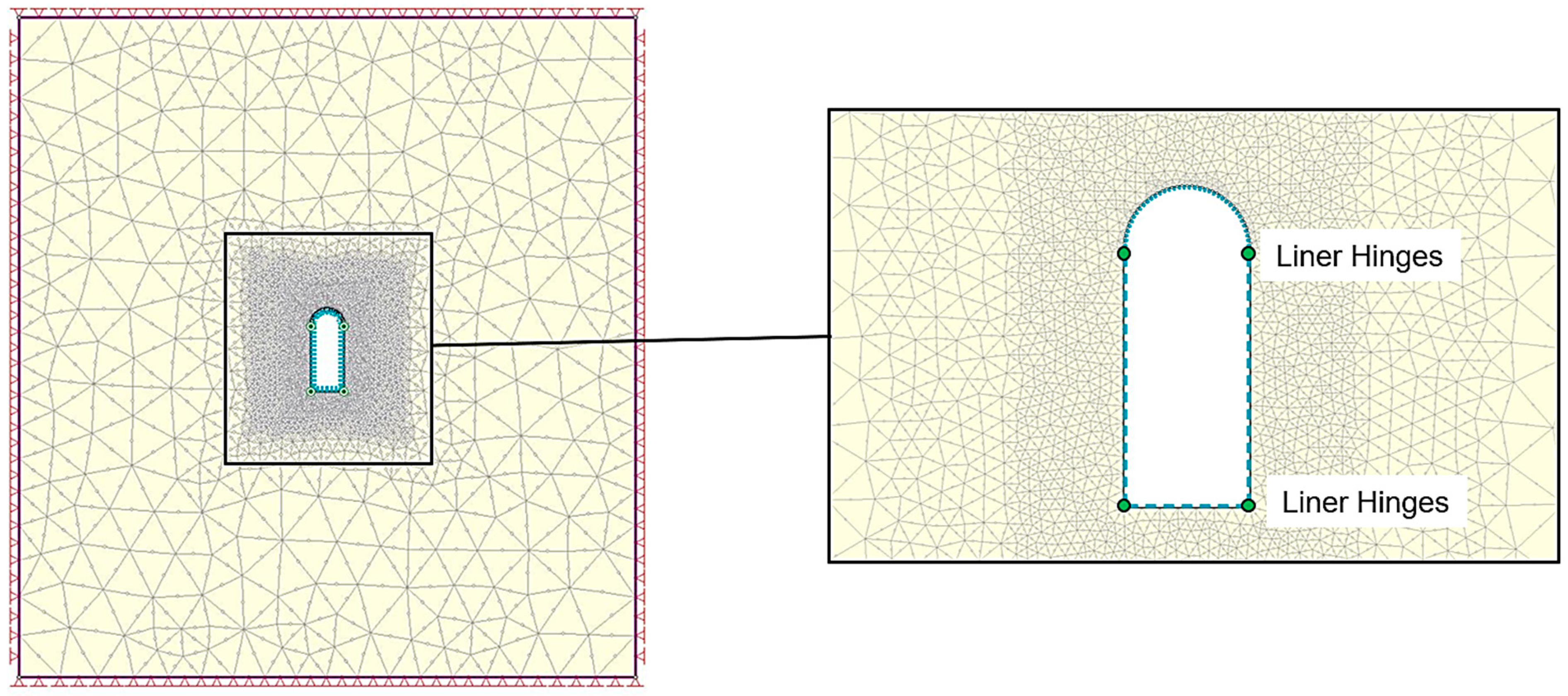
Due to the fact that the length of a tunnel is significantly larger than its height and width, a 2D plane-strain analysis is considered acceptable for most engineering purposes [15]. Therefore, the problem geometry can be regarded as constant in the out-of-plane axis. Consequently, for most tunneling applications, 2D numerical models are satisfactory. Nevertheless, it is important to consider that support installation usually takes place after some displacement of the tunnel walls has already occurred. The initial displacements impact the final state of the tunnel by both reducing the overall load imposed on the support system and any increasing displacements. The Longitudinal Displacement Profile (LDP) is a term that describes the deformation curve measured from the tunnel face to the point of support installation. Knowledge of the LDP can assist in the assessment of the magnitude of initial displacements induced prior to support installation. Ref. [16] used regression analysis from empirical data to develop a formula for the tunnel LDP. Ref. [17] proposed a modeling technique termed the Core Replacement Technique. Accordingly, 2D numerical models can be used to simulate the actual 3D effect of the distance of support installation to the tunnel face via an inclusion within the tunnel cavity that is flexible enough to allow the proper initial deformation.
According to accounts reported in the media (e.g., [6,18]), the Gaza tunnels vary in depth, but most tunnels range from depths of about 15 to 30 m below the surface. It is assumed excavation works were carried out using manual labor, primarily with shovels or with pneumatic jackhammers when denser soil was encountered. Following the progress of excavation, workers supported the tunnel walls, floor, and ceiling with thin concrete panels, which were possibly produced in the vicinity of the tunneling sites.
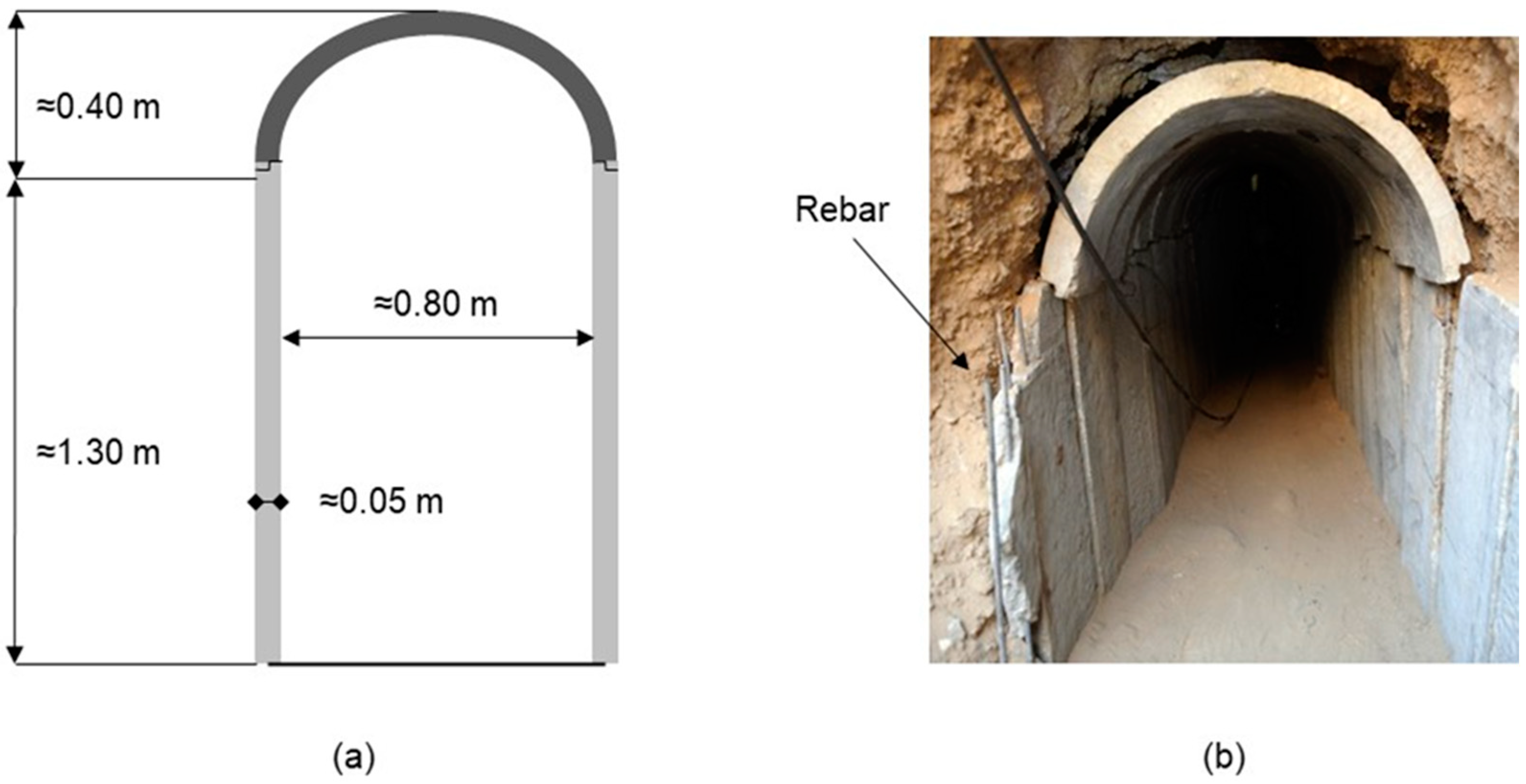
Tunnel dimensions were regularly minimal and allowed persons of average height to walk through while slightly bent. Dimensions of the tunnel support segments were estimated based on reports and open-source photos. 
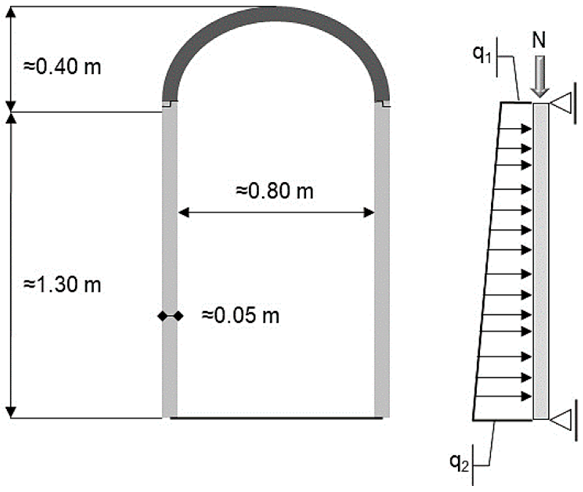
Figure 1a shows estimated tunnel dimensions and support thickness, while Figure 1b shows an actual example of one of the Gaza tunnels. The out-of-plane dimensions of the support segments are assumed to be approximately 30 cm.
Using the estimated dimensions, the weight of the wall elements is approximately 48–50 kg, thus allowing the segments to be erected manually. The very low thickness of the wall elements (approximately 5 cm) stands in contrast to its susceptibility to failure. The wall element can be assumed to be most susceptible to structural failure due to its considerably larger span compared to the floor and roof elements. As can be seen in Figure 1b, a broken tunnel wall element reveals that each segment consists of one layer of steel rebar placed in the center of the wall thickness. Steel bar diameter is estimated to be in the range of 8–10 mm. Note that according to mechanical theory, the location of the steel bars in the center of a cross-section (termed as the neutral axis) has a negligible contribution to the elements’ bending capacity, as maximum stresses occur at the element surfaces. Accordingly, the contribution of the steel rebar was neglected in the analyses carried out in the following section.
With respect to geology, the Gaza Strip sub-surface consists of Pliocene–Quaternary sediments varying from Pliocene sand dunes and alternating Pleistocene loess and gravels [19]. The more elevated layers are made of coastal sand dunes and alluvial deposits. The deeper layers consist of calcareous sandstones (locally termed ‘Kurkar’) and red sandy paleosoils (locally termed ‘Hamra’). The Kurkar is sporadically interbedded with clay, silt, and shale lenses which represent different periods of seawater transgressions and regressions of the Pleistocene age [20]. A typical cross-section of the soil layers from the Rafah district in southern Gaza is given by [21]. The climate of this region is arid, and the soil is dry.
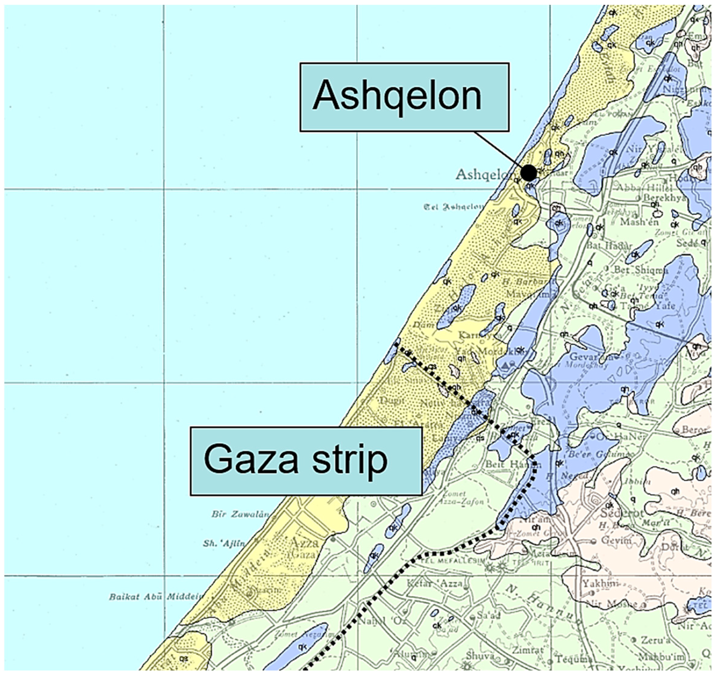
To better assess the engineering properties of the Kurkar sand in which the Gaza tunnels were constructed, requests to share data were sent to practicing engineers from Israel. Of primary interest are SPT measurements from the city of Ashqelon, which is located in close proximity to the Gaza Strip and lies upon the same geological formation (see Figure 2). Four reports from different sites in Ashqelon with a total of 13 boreholes were obtained. In these boreholes, SPT tests were conducted for the purpose of foundation analysis. Data from these tests show that in the Kurkar layers closer to the ground surface (<15 m), N values regularly fall in the range of 10–30, while at greater depths (15–30 m), N values are in the range of 30–70. At depths of 30 m below the surface and greater, the Kurkar may exhibit rock-like qualities. According to accepted guidelines (see Table 1), the soil around the tunnel can be considered.
From an engineering perspective, there is a tradeoff between tunneling in soft ground vs. hard ground. While it is significantly easier to excavate through softer material, on the other hand, the excavation is less stable, and the risk of collapse is greater, thus, requiring heavier support. Apparently, for the Gaza tunnels, excavation was preferentially limited to the upper layers of the Kurkar formation, most likely due to the manual excavation methods adopted. The input parameters estimated in the following section are based according to these assumptions. In geotechnical engineering practice, this information is considered sufficient for engineering judgment and evaluation of soil input parameters.

3. Analysis Methodology and Results

Despite the current knowledge gaps in geotechnical engineering, numerical analysis is often mistaken as a predictive tool [23]. However, the best use of numerical modeling is to study different scenarios and develop a risk strategy based on the modeled results. As shown in Figure 3, back-analysis is useful to understand processes and mechanisms, but even under the assumption that all conditions become known in the process (which for the problem under consideration is certainly not possible), there is no guarantee that the lessons learned from backward modeling could be used to predict future conditions. Therefore, rather than attempting to employ back-analysis techniques, we have analyzed the problem using a forward-analysis approach. The objective of our numerical simulations is not to determine precise material properties but to evaluate whether differences may exist between observed ground conditions and modeling results that cannot be attributed to changes in material properties alone.
A range of geotechnical properties is assessed in the models. Based on these ranges of properties, two types of analyses are conducted:
  • Simplistic structural analysis—in this analysis, the wall element is treated as a simply supported beam. The corresponding ground loads are computed according to standard geotechnical theory, and the wall element stresses are computed using basic mechanical theory.
  • Numerical analysis—in this analysis, finite-element models of the full soil medium and support elements are created and computed.

3.1. Simplistic Structural Analysis and Results

As discussed in Section 3, due to their significantly greater span, the wall segments are assumed to be the ‘weakest link’, i.e., they have the lowest capacity to carry the loads imposed by the ground; therefore, analysis in the section is focused on these elements. The wall segments are assumed here to be subjected to the earth’s lateral pressures. As the wall segments are bound by the roof and floor elements, they can be treated as a simply supported beam.
According to basic geotechnical theory, earth lateral pressures are equal to the product of the vertical stresses through the lateral coefficient denoted K. When a structure is restrained from movement in the lateral direction, the coefficient K is referred to as the at-rest coefficient Ko. One frequent example of such structures is basements, as their walls are assumed to be subjected to the at-rest earth pressures. For coarse-grained soils, Ko is traditionally assessed according to the analytical Jaky equation:
K o = 1 s i n
where ∅ is the internal friction angle of the soil.
Figure 4 shows an illustration of the tunnel wall beam model, where q1 and q2 are the beginning and end values of the trapezoidal load distribution. Accordingly, q1 and q2 are equal to:
q 1 = K o γ z 1
q 2 = K o γ ( z 1 + L )
where z1 is the depth below the surface at the upper point of the wall, L is the wall length, and γ is the soil density.
The maximum bending moments and shear forces are computed according to basic mechanical theory. The resultant compressive and tensile stresses due to the coupled effect of the axial forces and bending moments are computed according to the equation:
σ m i n m a x = N t ± M I t / 2
where N is the axial force, M is the bending moment, I is the inertial moment of the wall cross-section, and t is the wall thickness. Shear stresses are calculated according to Equation (5):
τ = V Q I t
where V is the shear force, Q is the first moment of area, I is the inertial moment, and t is the wall thickness.
Axial forces in the tunnel wall elements develop due to some interaction with the vertical stresses. In the current case, these stresses have a positive effect on the wall element stability, as they reduce the tensile stresses that result from the bending moment, as can be inferred from Equation (4). In general, when a circular underground cavity is formed, the major principal stresses flow around the cavity and concentrate at the minor principal stress axis. The vertical stresses are directly related to tunnel depth and influenced by the tunnel shape. To assess the magnitude of the axial force that develops in the tunnel wall elements, results from numerical methods were used. The numerical models are discussed in detail in the following Section 3.2.
Following the discussion given in Section 3, ranges for the relevant parameters are estimated. The wall segment dimensions (see Figure 1a) rely on estimation; hence, some variation is applied to these parameters. The parameters for the soil (i.e., soil density and friction angle) are based on the reviewed papers and typical ranges of SPT values obtained from the vicinity of the Gaza tunnels. The at-rest lateral pressure coefficient Ko is calculated according to the friction angle (see Equation (1)). A soil density of 20 kN/m3, typical for sandy soils, is assumed for all calculations. It is emphasized that it is not implied that the assumed ranges of parameters reflect the actual distribution of properties. On the other hand, given the great length of the tunnels, it is argued that at least some significant portion of the tunnels must have been excavated in this range of properties.
Another factor that has been estimated and incorporated into the calculations is the Relaxation Factor (RF). As explained in Section 2, the distance between the tunnel face and the supported portion of the tunnel dictates that an initial displacement occurs prior to support installation. The tunnel LDP is traditionally used to assess the percentage of relaxation. It is assumed that excavation is advanced in small steps, as the out-of-plane dimensions of the support elements are estimated to be approximately 30 cm. For the current case study, it is difficult to assess the proper RF, as tunnel LDPs were developed according to data from rock tunneling [16]. Hence, a wide range of 0–40% is examined for the relaxation factor. The axial force, bending moment, and shear force are multiplied by (1-RF).
The lower bound, upper bound, and mean input parameters, as well as computed results, are summarized in Table 2. The lower and upper bounds are defined in terms of the most and least favorable results in terms of the resultant stresses. It is noted that in terms of covariance between parameters, at greater depths, the Kurkar sand is generally denser, but the in situ stresses are higher. Hence, grouping together all lower bound and upper bound parameters is somewhat unrealistic. Nevertheless, the analysis here is only an attempt to provide some preliminary assessment of tunnel performance. The results are later discussed in Section 5.

3.2. Numerical Modeling Analysis and Results

Numerical modeling for geotechnical engineering has significantly developed over the past decades and has emerged as a powerful tool for the purposes of both research and practice. Numerical models explicitly consider the stresses and strains in the ground and support and can simulate complex scenarios, such as non-homogeneous soils and complex constitutive failure models. However, for this work, as no detailed data are available, adding complexity to the models would not contribute to result reliability. Therefore, the tunnels are modeled in a homogeneous medium, and an elasto-perfectly-plastic Mohr–Coulomb failure criterion is used. While more advanced constitutive models, such as the hardening-soil model, have been found to be more accurate in terms of displacement prediction, for the current application, the Mohr–Coulomb failure criterion has been found to yield acceptable results [24].
For the models in this paper, an elastoplastic analysis via the commercial program RS2 [25] was carried out. Similar to the methodology in the previous simplistic analysis, a range for each parameter has been estimated, and three models have been created. These models correspond to the lower bound, mean, and upper bound of the properties, as listed in Table 3. An additional input parameter that is required for numerical modeling is the soil’s Young’s modulus, Es. Soil Young’s modulus can greatly vary and is estimated from empirical correlations, laboratory test results on undisturbed specimens, and in situ tests [26]. Young’s modulus for Es is regularly in the range of 50–250 MPa; hence, values of 50, 150, and 250 that correspond to loose, medium, and dense sand configurations, are used for the models. A Poisson ratio of 0.25 is used for all models.
In order to account for the effect of relaxation, the core replacement technique proposed by [26] is applied. According to the assumed relaxation factor RF (see Table 3), Young’s modulus of the inclusion of the tunnel is reduced by a factor of (1-RF). Hence, every model consists of three stages: (1) the initial in-situ stage, (2) the core replacement stage, and (3) the support installation stage.
Figure 5 shows the model geometry and mesh discretization. The model boundaries are constrained in all directions. While for shallow tunnels, the surface boundary settles and should not be constrained, for the current case study, the zone of influence of the tunnel does not interact with the surface, even for the shallowest assumed depth (10 m). Six-noded triangular elements are used, with a graded mesh that is denser in the vicinity around the tunnel with a size of 0.4 m. A preliminary convergence test confirmed that this mesh configuration is satisfactory. For the liner support elements, hinges (marked as green circles in Figure 6) are assigned at the locations that correspond to the boundary between the roof, wall, and floor segments. Hinges dictate a zero-moment transfer and allow only the continuity of shear and axial forces. Liner support elements are modeled as an elastic material, customary for concrete structural analysis.
In addition to the models listed in Table 3, a model with no support was created and computed. As anticipated, the results of this model showed that the tunnel is not stable without support. The results of this model are shown in Figure 6. The elements that yield due to plastic failure are marked with ‘x’ signs. It can be noticed that the zone of plastic failure spreads outwards from the tunnel and reaches the model boundaries. This result indicates total failure, implying that without support, the tunnel will fail completely.
Results for the lower bound, mean, and upper bound models are summarized in Table 3. Note that the estimated parameters are identical to those in Table 2.

4. Discussion

Comparing the results from the simplistic analysis (Section 3.1) and numerical models (Section 3.2) shows that maximum bending moments and shear forces are higher for the former. The explanation for this difference is that in numerical modeling, rather than imposing the full lateral at-rest earth pressures upon the tunnel wall element, finite-element solutions implicitly account for the ground–support interaction. In this interaction, the ground has the capacity to carry a load, and therefore results are generally more realistic and less conservative [17].
The primary contributor to the resultant stresses in the wall elements is the axial force (not the bending moments). While no data were found regarding the strength of the concrete in the support segments, it is known that the concrete was produced secretly to avoid detection. Therefore, it would be highly unlikely that the concrete has high strength. For most building applications, concrete strength is in the range of 20–30 MPa. Comparing this strength to the computed compressive stresses shows that for both the lower bound and mean parameters, wall segments should fail.
The compressive stresses in the upper bound models are 10 and 19 MPa for the simple and numerical analysis. While this result obtained from the numerical model can be considered acceptable, under the stress computed in the simplistic analysis, some initiation of cracking would be expected. However, close observation of many photos published in the media of the Gaza tunnels does not reveal that such significant cracks developed.
As mentioned, instances of tunnel collapse and the deaths of workers have been reported in the media. However, it is not clear if these deaths occurred due to a collapse during an excavation prior to support installation or due to the collapse of the support elements themselves. Even if structural failure of the support occurred, this could be due to the improper erection of the support elements; for example, roof elements were not aligned with the wall elements. Ultimately, it is important to bear in mind that geological materials are heterogeneous by nature and that the strength of a given geological formation tends to follow a normal distribution. Given that a constant support system was applied, some percentage of failure would be inevitable. The fact that several miles of tunnels remained stable for years shows that the forward analysis assumptions made here, based on standard knowledge and practice, are highly conservative with respect to actual reality. It is emphasized that no safety factor was applied to the assumptions made here, and stresses were computed directly according to the estimated parameters. In other words, if the Gaza tunnels were to be constructed as a regular civil tunneling project, it is proper to assume that support elements would be increasingly heavier and operations considerably more costly.
The above is not to say that civil tunnels should be constructed in such a manner. Without a doubt, the safety measures of the Gaza tunnels are far from satisfactory, and tunneling projects should be completed with zero casualties. However, it is possible that the analysis here indicates that current guidelines for estimating strength parameters and lateral earth pressures in sand are biased toward conservatism, even prior to the application of safety factors.

5. Summary and Conclusions

The Gaza tunnels are a contemporary and unique example of a vast network of tunnels excavated in sand material, generally regarded as cohesionless soil. To the authors’ knowledge, the Gaza tunnels have yet to be discussed from a geotechnical engineering perspective.
As it is currently unfeasible to obtain direct access to field data from the tunnel sites, back-analysis modeling procedures are not feasible. Hence, we have attempted to analyze the problem using a “citizen science” approach by referring exclusively to material published in documents open to the public. Ranges for input parameters were assumed according to SPT tests conducted for the purpose of foundation design in the city of Ashqelon, which lies on the same geological formation as the Gaza Strip.
Two methods were used for analysis: simplistic analysis, based on the earth’s lateral pressures, and numerical analysis. Results using simplistic analysis were found to be more conservative. However, when compared to reality, it is safe to say that both methods yielded conservative results. This is made apparent from the results of compressive stresses computed in the tunnel wall support elements. While analysis results show that extensive cracking and failure would occur, reports show that this is not the case in reality.
Based on the current analysis, it is not possible to pinpoint the sources of this bias. It is the authors’ argument that the primary source of this bias stems from treating sands as cohesionless materials. While this assumption may be acceptable for common geotechnical applications (e.g., foundation design), it leads to over-conservatism with respect to the stability of underground excavations. Arguably, even a very low degree of cohesion can contribute greatly to the sand’s self-support capacity. Additionally, it is possible that the distribution of lateral stresses due to excavation defers from those obtained via simple analysis and numerical modeling.
It is the authors’ opinion that unique instances of structures such as in the current study, where the boundaries of engineering practice do not apply, serve as an important source for re-examining some of the fundamental assumptions that are regularly used in geotechnical engineering practice. Whether the source of this bias stems from neglecting the cohesiveness of granular soils or from a different reason requires additional studies.

Author Contributions

Conceptualization, D.E. and A.M.; methodology, D.E. and A.M.; software, A.M.; resources, D.E. and A.M.; writing—original draft preparation, D.E.; writing—review and editing, D.E. and A.M. All authors have read and agreed to the published version of the manuscript.

Funding

This research received no external funding.

Data Availability Statement

Some or all data, models, or code that support the findings of this study are available from the corresponding author upon reasonable request.

Acknowledgments

The authors wish to acknowledge the Livni engineers consulting firm for sharing relevant statistical data of SPT tests.

Conflicts of Interest

The authors declare no conflict of interest.

References

  1. Mitelman, A.; Elmo, D. A Proposed Probabilistic Analysis Methodology for Tunnel Support Cost Estimation Depending on the Construction Method. In Proceedings of the 52nd U.S. Rock Mechanics/Geomechanics Symposium, Seattle, WA, USA, 17–20 June 2018; p. 8. [Google Scholar]
  2. Hemphill, G.B. Practical Tunnel Construction; John Wiley & Sons: Hoboken, NJ, USA, 2012. [Google Scholar]
  3. Olson, K.R.; Morton, L.W. Why Were the Soil Tunnels of Cu Chi and Iron Triangle in Vietnam So Resilient? Open J. Soil Sci. 2017, 7, 34–51. [Google Scholar] [CrossRef] [Green Version]
  4. Slesinger, I. A cartography of the unknowable: Technology, territory and subterranean agencies in Israel’s management of the Gaza tunnels. Geopolitics 2020, 25, 17–42. [Google Scholar] [CrossRef] [Green Version]
  5. Bartolomeu, J.P.S. Operations in subterranean systems: Terrain and weather variable. Secur. Def. Q. 2020, 29, 39–60. [Google Scholar] [CrossRef]
  6. Watkins, N.J.; James, A.M. Digging into Israel: The sophisticated tunneling network of Hamas. J. Strateg. Secur. 2016, 9, 84–103. [Google Scholar] [CrossRef] [Green Version]
  7. Lee, K.A.; Lee, J.R.; Bell, P. A review of Citizen Science within the Earth Sciences: Potential benefits and obstacles. Proc. Geol. Assoc. 2020, 131, 605–617. [Google Scholar] [CrossRef]
  8. Tonon, F. Sequential excavation, NATM and ADECO: What they have in common and how they differ. Tunn. Undergr. Space Technol. 2010, 25, 245–265. [Google Scholar] [CrossRef]
  9. Terzaghi, K. Geological Aspects of Soft Ground Tunnelling; John Wiley & Sons: New York, NY, USA, 1950. [Google Scholar]
  10. Heuer, R.E. Important ground parameters in soft ground tunneling. In Proceedings of the Subsurface Exploration for Underground Excavation and Heavy Construction, Henniker, NH, USA, 11–16 August 1974; pp. 41–55. [Google Scholar]
  11. Hashemnejad, A.; Hassanpour, J. Proposed soil classification based on the experiences of soft-ground tunneling in Iran. Bull. Eng. Geol. Environ. 2016, 76, 731–750. [Google Scholar] [CrossRef]
  12. Taromi, M.; Eftekhari, A.; Hamidi, J.K.; Aalianvari, A. A discrepancy between observed and predicted NATM tunnel behaviors and updating: A case study of the Sabzkuh tunnel. Bull. Eng. Geol. Environ. 2016, 76, 713–729. [Google Scholar] [CrossRef]
  13. N.H.I. (US); Parsons; Brinckerhoff; Quade & Douglas. Technical Manual for Design and Construction of Road Tunnels—Civil Elements; AASHTO: Washington, DC, USA, 2010. [Google Scholar]
  14. Budhu, M. Soil Mechanics and Foundations, 1st ed.; Wiley: Hoboken, NJ, USA, 2020. [Google Scholar]
  15. Mitelman, A.; Elmo, D. Analysis of tunnel-support interaction using an equivalent boundary beam. Tunn. Undergr. Space Technol. 2018, 84, 218–226. [Google Scholar] [CrossRef]
  16. Chern, J.C.; Shiao, F.Y.; Yu, C.W. An empirical safety criterion for tunnel construction. In Proceedings of the Regional Symposium on Sedimentary Rock Engineering, Taipei, Taiwan, 20–22 November 1998; pp. 222–227. [Google Scholar]
  17. Hoek, E.; Carranza-Torres, C.; Diederichs, M.; Corkum, B. Integration of geotechnical and structural design in tunnel-ling—2008 Kersten Lecture. In Proceedings of the University of Minnesota 56th Annual Geotechnical Engineering Conference, Minneapolis, MI, USA, 29 February 2008; pp. 1–53. [Google Scholar]
  18. Newman, M. Israel Announces It Won’t Cooperate with UN Gaza Probe. The Times of Israel, 15 November 2014. [Google Scholar]
  19. El-Khoudary, R.H.; Anan, H.S. Preliminary study on the geology and geomorphology of Wadi Gaza, Gaza Strip. In Proceedings of the 2nd Jordanian Geological Conference, Amman, Jordan, 22–24 April 1985; pp. 531–539. [Google Scholar]
  20. Issar, A. Geology of the central coastal plain of Israel. Isr. J. Earth Sci. 1968, 17, 16–29. [Google Scholar]
  21. Zaineldeen, U.; Qahman, K.; Al-Dasht, J. Geological structure of the coastal aquifer in the southern part of the Gaza Strip, Palestine. Arab. J. Geosci. 2013, 7, 4343–4354. [Google Scholar] [CrossRef]
  22. Sneh, A.; Bartov, Y.; Weissbrodt, T.; Rosensaft, M. Geology Map of Israel, 1: 200,000, 4 Sheets; Geological Survey of Israel: Jérusalem, Israel, 1998. [Google Scholar]
  23. Elmo, D.; Mitelman, A.; Yang, B. Examining Rock Engineering Knowledge through a Philosophical Lens. Geosciences 2022, 12, 174. [Google Scholar] [CrossRef]
  24. Obrzud, R.F. On the use of the Hardening Soil Small Strain model in geotechnical practice. Numer. Geotech. Struct. 2010, 16, 1–17. [Google Scholar]
  25. Rocscience. Phase2, Version 6.020; Rocscience Inc.: Toronto, ON, Canada, 2007.
  26. Cohen, S.; Mitelman, A.; Elmo, D. A Methodology for the Analysis of Tunnel Intersections Using Two-dimensional Numerical Modeling. IOP Conf. Ser. Earth Environ. Sci. 2023, 1124, 012069. [Google Scholar] [CrossRef]
Figure 1. Dimensions of a typical Gaza tunnel. (a) estimated concrete segment dimensions, and (b) actual field photo (David Buimovitch/AFP/Getty Images).
Buildings 13 00713 g001
Figure 2. Geological map of southern Israel and the Gaza Strip (modified from [22]).
Buildings 13 00713 g002
Figure 3. Impact of knowns and unknowns on forward and backward modeling processes.
Buildings 13 00713 g003
Figure 4. Tunnel wall beam model.
Buildings 13 00713 g004
Figure 5. Tunnel model geometry and mesh discretization.
Buildings 13 00713 g005
Figure 6. Results of yielded elements against contours of total displacements for model of tunnel with no support.
Buildings 13 00713 g006
Table 1. Correlation of SPT values for coarse-grained soils (from [15]).
NCompactnessUnit Weight
[KN/m3]
Friction Angle
[degrees]
0–4Very loose11–1326–28
4–10Loose14–1629–34
10–30Medium17–1935–40
30–50Dense20–2138–45
>50Very dense>21>45
Table 2. Estimated parameters and computed results for tunnel wall elements.
ParameterUnitsLower BoundMeanUpper Bound
Estimated parametersWall thicknessM0.040.050.06
Wall lengthM1.51.41.3
Wall depthM302010
Friction angleDegrees253545
Lateral stress coefficient-0.580.430.29
Relaxation factor-0.000.200.40
Computed resultsAxial forcekN/m35212943
MomentkNm/m100348
Shear forcekN/m26912641
Compressive stressMPa2488519
Shear stressMPa1031
Table 3. Numerical model estimated parameters and results.
ParameterUnitsLower BoundMeanUpper Bound
Estimated parametersWall thicknessm0.040.050.06
Wall lengthm1.51.41.3
Wall depthm302010
Friction angledegrees253545
Lateral stress coefficient-453525
Relaxation factor-00.20.4
Computed resultsAxial forcekN/m3521624
MomentkNm/m23124
Shear forcekN/m73162352
Compressive stressMPa643210
Shear stressMPa246397
Disclaimer/Publisher’s Note: The statements, opinions and data contained in all publications are solely those of the individual author(s) and contributor(s) and not of MDPI and/or the editor(s). MDPI and/or the editor(s) disclaim responsibility for any injury to people or property resulting from any ideas, methods, instructions or products referred to in the content.

