Article

Experimental Study on Seismic Behavior of Damaged Beam-Column Joints Retrofitted by Viscoelastic Steel-Enveloped Elements

1
Shenzhen Research Institute, Southeast University, Nanjing 211189, China
2
China-Pakistan Belt and Road Joint Laboratory on Smart Disaster Prevention of Major Infrastructures, Southeast University, Nanjing 211189, China
3
Changzhou Shengfang Construction Development Co., Ltd., Changzhou 213001, China
*
Author to whom correspondence should be addressed.
Buildings 2023, 13(3), 702; https://doi.org/10.3390/buildings13030702
Submission received: 30 December 2022 / Revised: 1 March 2023 / Accepted: 2 March 2023 / Published: 7 March 2023
(This article belongs to the Special Issue Dynamics Analysis of Structures with Viscoelastic Elements)

Abstract

:
In order to improve the seismic performance of damaged reinforced concrete joints, a new retrofitting method using viscoelastic materials and steel plates is proposed. A reversal cyclic loading test was carried out on four T-shaped RC joints to investigate the reliability of this method. Seismic performance, including the strength, stiffness, ductility, and energy dissipation capacity of the original non-damaged joint and different repaired and retrofitted joints are then compared. The results show that this new method can significantly improve the strength of the retrofitted joints, and the joints can be loaded to a larger displacement value. After retrofitting, the energy dissipation of the joints increases, and the stiffness degradation decreases. The test results indicate that the retrofitting method is effective in repairing seismically damaged RC joints.

1. Introduction

Numerous investigations have demonstrated that the failure of beam-column joints in reinforced concrete (RC) moment frame structures following earthquakes is a common and unavoidable phenomenon. The role of beam-column joints in providing lateral stability to reinforced concrete moment frame structures is critical. Even a minor failure of these joints can lead to a progressive collapse of the building. As a consequence, retrofitting or repairing RC beam-column joints is of utmost importance, and various theoretical and experimental studies have been conducted to investigate the retrofitting of beam-column joints in concrete frame structures [1,2,3,4,5,6,7,8,9]. Currently, the prevailing retrofit and strengthening methods for RC joints include the enlargement of the section, steel-envelopment, and fiber-envelopment methods. Other, less commonly used methods include the prestressed tie rod method, the steel mesh with sheet-polymer mortar method, and strengthening with replacement mortar.
Pimanmas and Del Vecchio conducted experimental studies on the joints retrofitted with enlarging cross-sections, and the reinforced joints show good performance [2,3]. Biddah and Lu proved, through experiments, that steel-enveloped method can significantly improve the strength and ductility of beam-column joints [4,5]. Parvin and Akguzel used CFRP and GFRP materials to retrofit the joints, and conducted experimental studies [6,7]. The results show that this retrofitting method can effectively protect the joint area from shear damage. Yurdakul studied the effectiveness of the retrofitting method using external post-tensioning rods, and the results showed that the ultimate capacity of all retrofitted specimens was greatly improved [8]. Cao conducted an experimental study on the method of retrofitting RC joints with high-strength steel mesh and polymer mortar, and the performance of the joints was greatly improved after retrofitting [9].
The retrofitting methods of earthquake-damaged RC joints are similar to that of non-damaged RC joints. Tsonos conducted an experimental study on the performance of the joints, which were retrofitted by steel-envelopment, retrofitted with carbon fiber, and reinforced with concrete-envelopment, before and after damage [10]. The test showed that the three retrofitting methods all have a positive effect on the joints. The reinforcement effect is very significant. Wong used the steel-enveloped retrofitting method to retrofit the reinforced RC joints after earthquake damage and studied The impact of steel plate thickness and the interface grouting material [11]. The results showed that the thickness of the outer steel plate has an effect on the performance of the joints. The type of interface grouting material has a negligible impact on the performance of the joints. Faella compared the seismic performance of the joints retrofitted with carbon fiber and retrofitted using the steel-enveloped method after earthquake damage [12]. The results show that the effect of steel-envelopment is better than that of carbon fiber-enveloped reinforcement. Zhang introduced a novel method for retrofitting severely damaged reinforced concrete frames by using sector lead viscoelastic dampers. Experimental results verified that this retrofitting method is effective in safeguarding the beam-column joint zone and improving the horizontal load-carrying capacity, initial stiffness, and secant stiffness of the damaged RC frame [13]. Esmaeeli proposed a cast-in-situ retrofitting strategy using CFRP reinforced SHCC (strain hardening cementitious composite), The test results indicate that the performance of the proposed technique is significantly influenced by the bond strength between the retrofitting system and the concrete [14]. Cai et al. proposed a steel haunch system aimed at retrofitting reinforced fire-broken concrete column-beam-slab joints and enhancing their seismic performance. In addition, the steel haunches showed excellent compatibility with carbon fiber reinforced polymer bolted side plates and sheets [15]. Sharma and Bansal carried out an experimental investigation to assess the effectiveness hybrid fiber reinforced concrete with ultra high performance in retrofitting. The test results illustrate that the performance of BCJ is influenced by the initial level of damage. As the initial level of damage increases from minor to severe, the stiffness, ductility, strength retention at higher drift levels, and energy dissipation all decrease [16]. Zaferani and Shariatmadar investigated the retrofitting and repair of external reinforced concrete beam-column joints using fiber-reinforced polymer composites by conducting experimental tests. indicated that the proposed techniques are capable of restoring the lost joint performance, and even surpassing the performance of the control specimen [17]. Dong proposed an innovative method to retrofit reinforced concrete framed structures with high-performance acrylate viscoelastic dampers, and the research results demonstrate that the proposed method has excellent energy dissipation capability [18].
The aforementioned retrofitting methods have all demonstrated their efficacy; however, they exhibit different degrees of improvement in joint performance. Liao compared the seismic performance of joints retrofitted using different methods, including increasing cross-section, steel jacketing, carbon fiber, basalt fiber, and steel strand polymer mortar retrofitting methods [19]. The results showed that strengthening with the steel jacketing retrofitting method had the best effect.
The steel-enveloped method is proved to significantly enhance the seismic performance of the stiffness and strength of the damaged RC joints. On the other hand, viscoelastic materials are considered to be engineering materials with excellent energy dissipation and deformation capabilities for enhancing the seismic performance of engineering structures [20]. This paper proposes a novel method of retrofitting and strengthening seismically damaged joints by combining the advantages of two concepts: the steel-enveloped method and the use of viscoelastic materials. The experiments were conducted on RC joints with different seismic damage levels after retrofitting by the proposed method involving the use of viscoelastic steel-enveloped elements.

2. Experimental Program

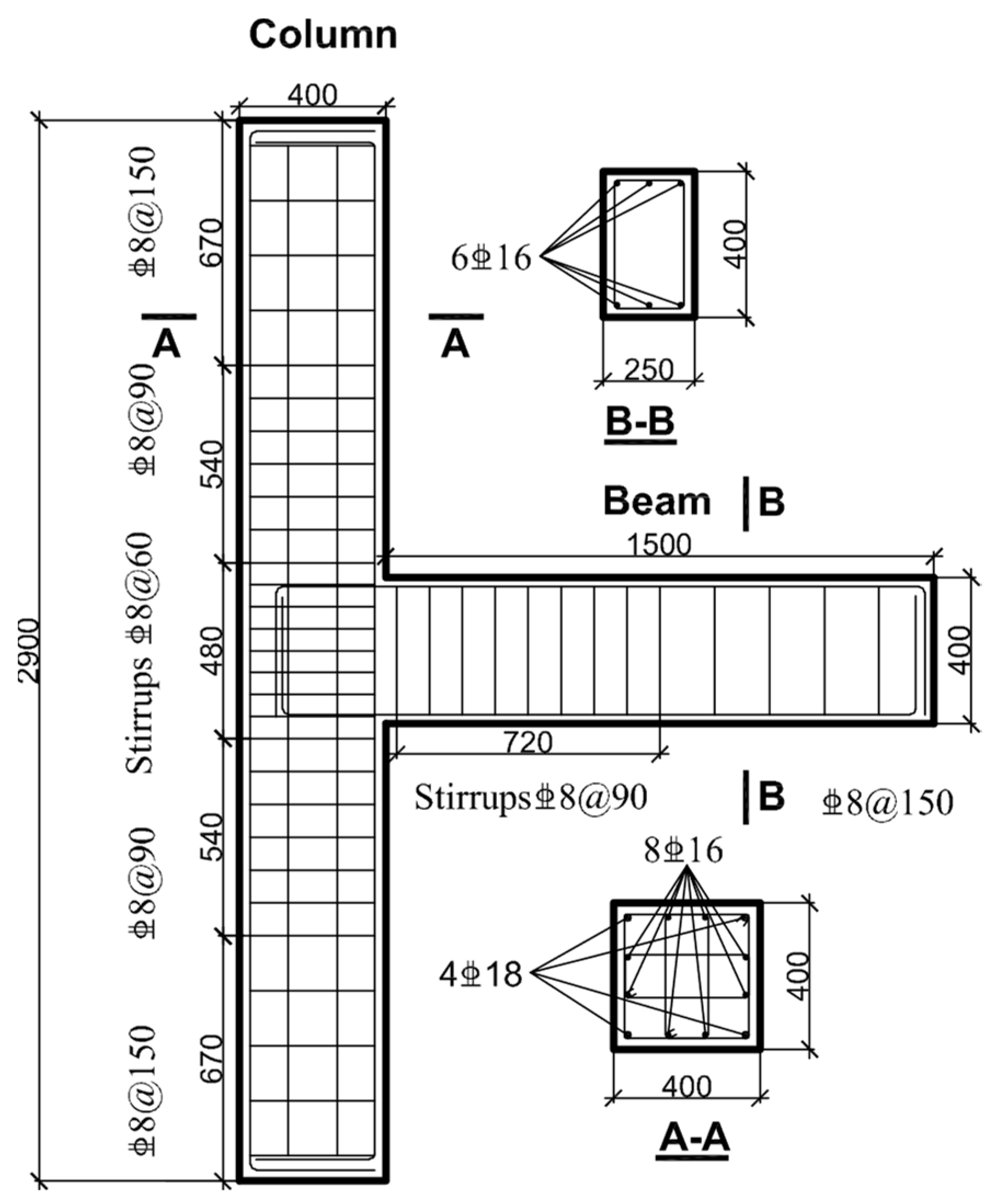
2.1. Specimen Information

A total of 4 full-scale reinforced concrete T-shaped joint specimens are designed and constructed in this experiment, labeled as J0, JR1, JR2, and JR3, respectively. J0 is a non-damaged joint specimen used for comparison. The design of J0 takes into account both the maximum output power of the testing machine and the reinforced concrete structures design code. During the test, it is directly loaded with rapid cyclic loading until it fails; JR1, JR2, and JR3 are pre-damaged RC joints, retrofitted by different viscoelastic steel-enveloped elements. The retrofitted elements of the three specimens are similar, except for the absence of viscoelastic material in the retrofitting of JR1. In the JR2 specimen, 10 mm thick viscoelastic pads are pasted between the inner surface of the U-shaped steel sleeve and the upper and lower surfaces of the beam, while in the JR3 specimen, 18 mm thick viscoelastic pads are pasted at the same position. The different parameters of the specimens are shown in Table 1. The concrete designed strength grade of the specimens is C40, and the steel grade is HRB400. C40 concrete has a mix ratio of 1:1.5:3, and its concrete strength is 40 Mega Pascal. The mechanical properties of the materials used in the test are listed in Table 2. The section size of the column and beam is 200 mm × 200 mm, and 150 mm × 300 mm, respectively. The length of the beam and column is 1500 mm and 2900 mm, respectively. The details of the specimens are shown in Figure 1. Before the test, JR1, JR2, and JR3 specimens are subjected to pre- damage tests with cyclic loading, and then the method proposed is used for retrofitting.
The objective of the experiment is to compare the effectiveness of different viscoelastic pad thicknesses and their impact on the seismic performance of the joint. The scope of seismic damage to the joint will also be examined through a comparison of various specimens. During the test, deformation of the viscoelastic material will be observed, and parameters such as hysteretic curve, skeleton curve, stiffness degradation, ductility coefficient, energy dissipation, equivalent viscous damping coefficient, steel plate strain, and joint deformation will be measured. These observations will enable the accurate evaluation of the seismic performance of each specimen.

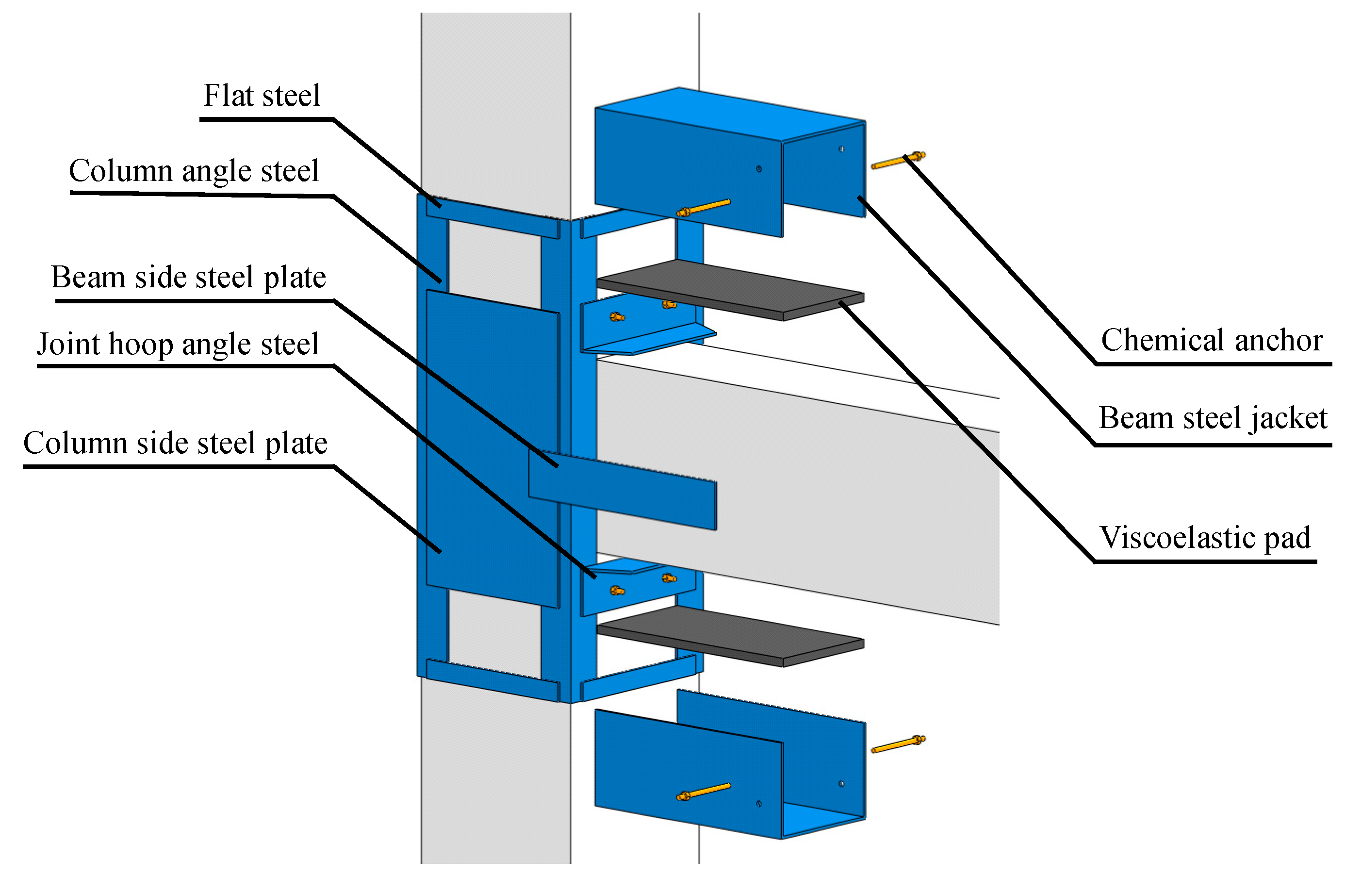
2.2. Viscoelastic Steel-Enveloped Rehabilitated Method

The steel grade used is Q335, and the thickness of steel plate and angle steel are both 6 mm. In order to efficiently connect steel plates and RC joints, M12 type chemical anchor bolts were utilized in this study. In structural engineering, a chemical anchor bolt is a composite component that fixes a threaded rod in a drilled hole of concrete by using a special chemical adhesive to provide anchorage for the fixed part. The M12 type chemical anchor bolts are commonly used for efficiently connecting steel plates and RC joints. In general, the M12 type chemical anchor bolts have a maximum tested force 15 KN, and they are typically used between 12 and 13 KN. The chemical anchor bolts used in this study are composed of 5.8 grade carbon steel.
The viscoelastic material used is a nitrile rubber-based viscoelastic material, specially made by the research group. Specifically, this material is made up of a high polymer, with a nitrile butadiene rubber matrix that has been vulcanized at a high temperature and pressure with a range of additives, such as vulcanizing agents, accelerators, anti-aging agents, reinforcing agents, plasticizers, etc. The dynamic mechanical performance tests was evaluated through tests at varying environment temperatures, displacement amplitudes, and loading frequencies. The results indicate that the viscoelastic damper show outstanding stiffness and energy dissipation capacity under different loading case [20,21]. The storage modulus of the material is 1.47 MPa, and the loss factor is 1.26 at an excitation force of 1 Hz and a temperature of 15.2 °C. The three-dimensional schematic diagram of the viscoelastic steel-enveloped retrofitting method is shown in Figure 2.
The range of the retrofitted column is 500 mm above and below the center of the joint, so the total length of the column reinforcement is 1000 mm, as shown in Figure 3. The enveloped steel elements mainly include: L80 angle steel in the column foot, flat steel, and large steel plates on the three sides of the column. The angle steel is wrapped at the four corners of the column, and the remaining steel plates are distributed on the four sides of the column, with a certain length of overlap with the angle steel. All the steel plates are welded together to form a single entity. All steel plates on the columns of the reinforced specimens are firmly bonded with the concrete using structural glue, enabling them to work as a cohesive unit. The density of the adhesive material is 1.6 g/cm3. After the application of the adhesive, the steel plate bonding material exhibits an adhesive failure strength of 3.4 MPa. Meanwhile, the adhesion failure strength between the viscoelastic pad and the concrete side colloid is 0.396 MPa, and that between the viscoelastic pad and the steel plate side colloid is 0.581 MPa.
The retrofitted steel around beam extends from the surface of the column and spans 500 mm along the direction of the beam. The steel plates used for reinforcement mainly include the upper and lower U-shaped steel sleeves and the long steel plates on both sides. The upper and lower U-shaped steel sleeves are cold-formed from a single piece of steel plate cut into appropriate sizes. Two bolt holes are drilled on the side head of the U-shaped steel sleeve for the passage of the chemical anchor bolt. The inner space between the two wing plates of the steel sleeve should be slightly larger than the size of the beam section to facilitate the injection of adhesive into the gap between the steel plate and the concrete. The two U-shaped steel sleeves do not touch the edges of the side of the beam, which allows for convenient adjustment of errors during the retrofitting process. Two long steel plates are arranged at the center of the beam side and welded with two U-shaped steel sleeves. A certain length of L100 angle steel hoop is set at the right angle between the upper and lower beams and the column. The angle steel hoop is welded to the angle steel of the column, and is simultaneously anchored using chemical anchor bolts. The angle steel hoop is also outside the U-shaped steel sleeve on the beam side. The surface is tightly welded. The main reinforcement construction processes on the pre-damage specimens are shown in Figure 4.
JR1 adopts the pure-enveloped steel reinforcement method to strengthen the joints after an earthquake. The beam steel sleeve of the test specimen is firmly bonded to the beam concrete using structural adhesive, and no chemical anchor bolts are used to anchor the side of the beam steel sleeve. Viscoelastic pads are placed between the concrete and the steel sleeve on the upper and lower surfaces of the beam in the JR2 and JR3 specimens. The upper and lower surfaces, respectively, of the viscoelastic pad are bonded to the steel plate and the concrete. The specimens are only filled with structural adhesive between the column steel sleeve and the column surface. The beam steel sleeve is anchored to the beam concrete using chemical anchor bolts, and no structural glue was injected between the beam steel sleeve and the beam concrete. A viscoelastic pad is attached to the center of the beam surface, with a length of 500 mm, which is the same as the length of the beam steel sleeve. The width of the pad is 230 mm, which is 20 mm less than the width of the beam, and there are 10 mm gaps between the left and right sides and the U-shaped steel sleeve wing plates. The thickness of the viscoelastic pad of the JR2 specimen is 10 mm, and the thickness of the viscoelastic pad of JR3 is 18 mm.

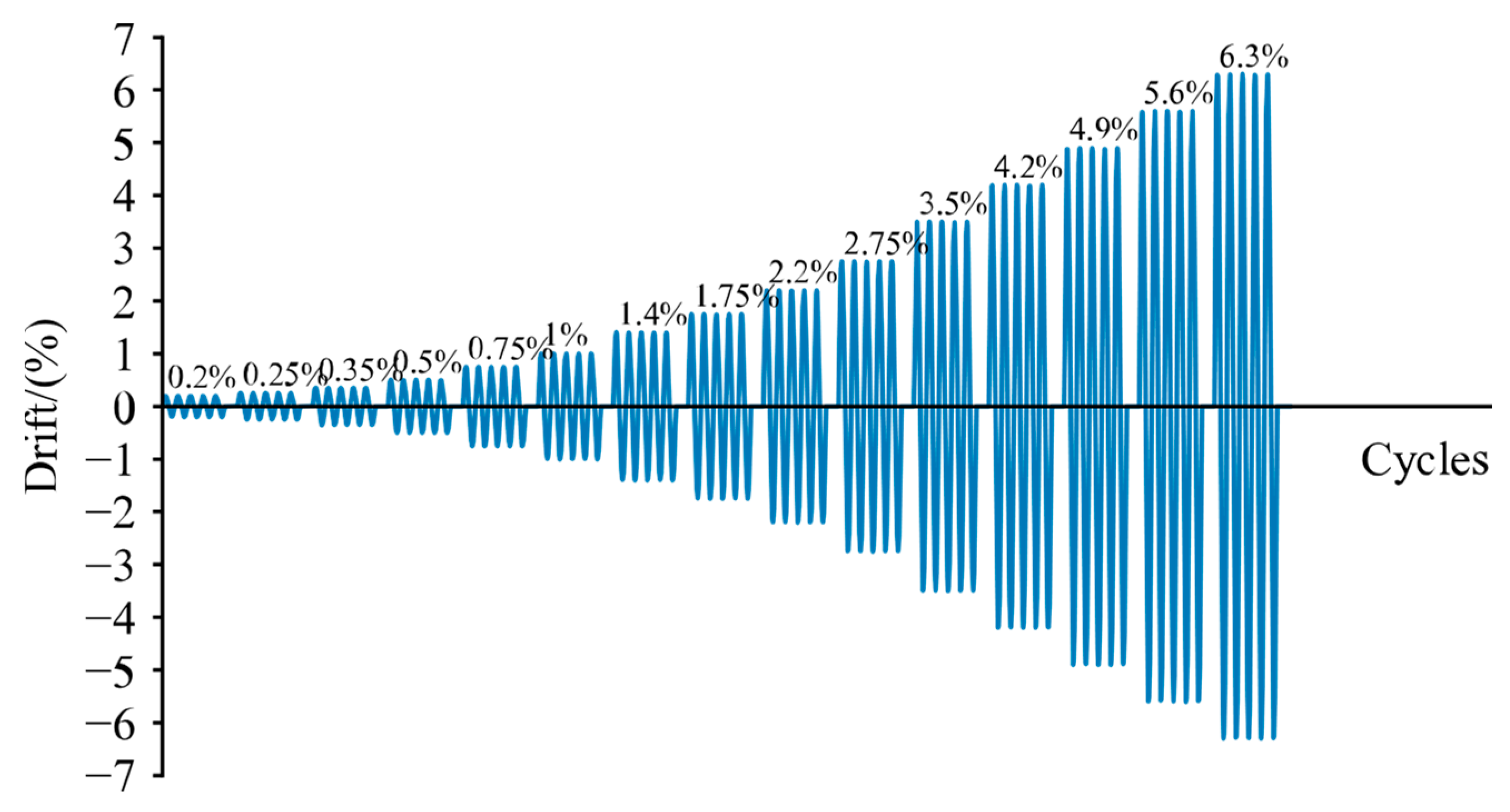
2.3. Test Setup, Loading Protocol, and Instrumentation

Considering the existing conditions of the laboratory and referring to the test methods, the loading position is set at the end of the beam [22], and the test setup shown in Figure 5 is used.
Due to the constraints of the test loading equipment, the lateral loading method was adopted in the test. This means that the joint column was placed horizontally on the ground, while the beam ends were loaded laterally. In other words, the test model of the beam-column joint was oriented at 90 degrees, with the column in the horizontal direction and the beam in the vertical direction. The loading device is mainly composed of MTS actuators fixed on the wall, beam end chucks, hydraulic jacks at both ends of the column, reaction beams, and hinged supports under the column. The primary function of the hinged support is to facilitate the free rotation of the column end during the loading process, thereby simulating the rotational displacement at the position of the column’s reverse bending point in the actual structure. The photograph of actual loading is shown in Figure 6.
This test is conducted following the recommended practices for the American Concrete Association Test [23], wherein the displacement angle is directly used to control the loading. Different from the pseudo-static loading test, this test uses a fast cyclic loading method. Based on the performance of the viscoelastic material, the loading frequency that can best exhibit the properties of the material was determined. The test method of Wu [24] is also taken into consideration, and a loading frequency of 2 Hz was selected for this test. To better evaluate the hysteretic performance of the joint with the viscoelastic pad under the fast loading rate, each drift level is loaded with five cycles [25]. The specific parameters of the test loading control are shown in Table 3, and the loading history is shown in Figure 7.
The pre-damage test applies a fast loading method similar to the loading process in the above paragraph, but with simplified displacement levels, requiring loading displacement amplitudes of 0.5%, 1%, and 2%. In addition, the number of cycles for each level of loading is reduced to three times.
In order to simulate the real situation, it is necessary to apply axial force to the ends of the column. According to the design calculation of a real frame, the axial compression ratio of the column during the test is set to 0.15.
The loading process for the non-damaged joints in this test is as follows: 1. Apply the hydraulic jack to the calibrated oil pressure, corresponding to the predetermined axial force; 2. Perform the first stage 0.2% displacement angle loading. At this time, the structure is in the elastic range, and no obvious damage will occur; 3. Check to determine whether the fixing device of the specimen is loose and ensure that the equipment is operating correctly; 4. Proceed to the next stage of loading; pause after the five cycles of each stage of loading to observe the damage of the specimen; and 5. Destruct the specimen when the ultimate load of the specimen drops to 85% of the ultimate load during the entire test process. The specimen is considered damaged, and the test concludes.
The loading process of the retrofitting joints in the test is as follows: 1. Carry out the pre-damaged test; 2. Perform the loading process for the reinforced specimens following the process detailed above for non-damaged joints nodes.

3. Results and Discussion

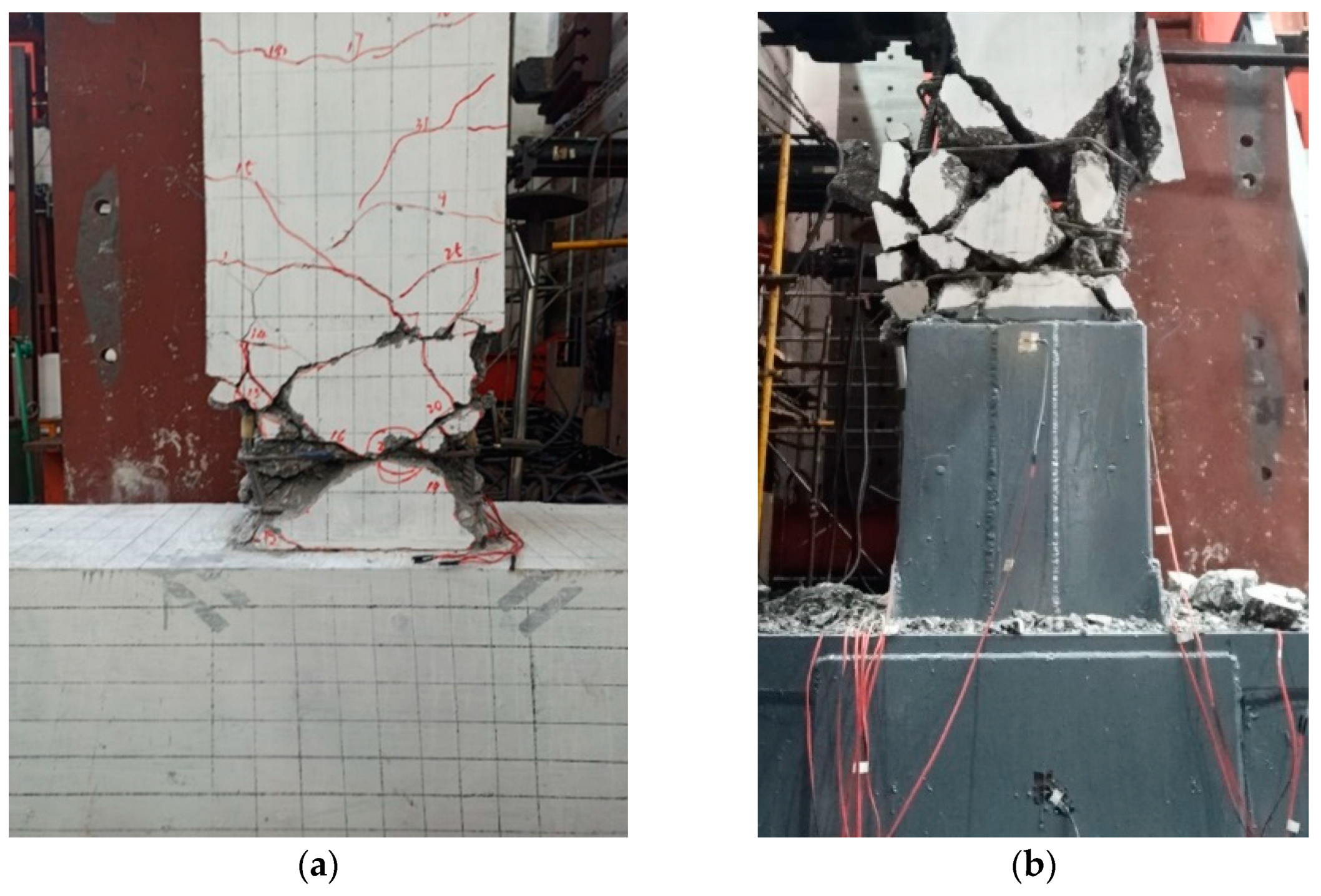
3.1. Experimental Phenomena and Damage Progression

In specimen J0, no significant cracks were observed on the surface of the beam and column during the non-destructive test at the first three drift levels. At 0.5% drift, cracks appeared at the joint between the root of the beam and the cylinder surface, and numerous cracks started to emerge on the beam. At 1.4% drift, wide cracks appeared, with a width of up to 2 mm. The center, at 20 mm from the cylindrical surface, expanded obliquely, and X-shaped cross-distributed cracks appeared at multiple positions on the front of the beam. At 1.75% drift, an obvious plastic hinge was formed on the front of the beam. At 2.75% drift, the right side of the beam continued to crack, and new cracks appeared. At the end of the right beam, a large concrete block peeled off, and concrete block peeling also occurred at the plastic hinge on the front side. Subsequently, the concrete continued to peel off, and the bearing capacity continued to decrease. At 4.2% drift, the capacity dropped to 61.4 kN, and the loading was stopped.
In specimen JR1, no rubber pads were used for the retrofitting. During the loading process from the fifth to the eighth level, small cracks continued to appear on the front and side of the beam, as well as on the upper side of the outer steel. At a drift of 2.2%, an evident cracking sound was heard, and small pieces of concrete continuously detached from the front side of the beam. At a drift of 2.75%, the concrete continued to spall at the intersection of the cracks, and new transverse cracks continued to develop in the upper portion. At a drift of 3.5%, the concrete on the upper side of the outer steel at the front of the beam spalled in multiple places, while the concrete on the left and right sides was crushed into blocks. At a drift of 4.2%, large concrete blocks detached from the left, right, and central portions of the beam, resulting in the exposure of the longitudinal reinforcement and stirrup inside the beam, and the maximum load dropped below 60 kN.
In the destruction process of specimen JR2, no obvious damage was observed for the first four drift levels of loading. Small cracks appeared out of the steel during the fifth and sixth levels of loading. At drift 1.75%, large cracks appeared on the left side of the beam, and more micro-cracks appeared on the front side. At a drift of 2.2%, X-shaped crack intersections appeared in the bottom, parallel to the edge of the outer steel. The crack was wider, with a width of about 2 mm. At a drift of 2.75%, the cracks on the front side of the concrete beam continued to expand and widen, with concrete fragments continuously falling during the loading process. At a drift of 4.2%, the concrete on the front side of the beam near the edge of the outer steel was continuously crushed, and the maximum crack reached 10 mm. New and wider X-shaped cross cracks continued to appear on the side, with the cracks extending to the end of the beam. At a drift of 4.9%, the concrete near the steel plate at the center of the X-shaped cross cracks on the left and right sides of the beam was severely damaged, resulting in a large amount of concrete spalling on the surface. The concrete on both sides was also broken into large pieces. At a drift of 5.6%, the outer concrete of the steel bar within 500 mm outside the outer steel range of the front and side of the beam was almost completely peeled off, and the internal main reinforcement was obviously bent. In the fifth lap, the maximum load dropped to about 70 kN, and the test was stopped. Finally, a large bulge of the steel plate at the end of the outer steel coated with rubber pads was observed. The failure modes of all specimens are shown in Figure 8.

3.2. Hysteresis Curves

The hysteresis curves of different beam column joints, J0, JR1, JR2 and JR3, are shown in Figure 9. The height of the hysteresis curve of the specimen J0 is lower, reflecting the lower strength after the test piece yields. In contrast, the height of the hysteresis curve of the JR1-JR3 test piece is higher. It can be seen that the ultimate strength is close to 120 kN at the highest points for JR1~JR3, which is much higher than the ultimate strength of about 80 kN of the comparative specimen J0. It can be shown that the strength of the seismically damaged joint after retrofitting can be significantly improved. In particular, it should be noted that the JR2 and JR3 specimens are retrofitted with viscoelastic pads, and the beam steel sleeve is not bonded to the surface of the beam concrete, while the JR1 specimen beam steel sleeve is tightly bonded to the outer surface of the beam concrete. The ultimate strength of the joints retrofitted using the viscoelastic steel-enveloped method is comparable to that of the joints strengthened solely by the steel-enveloped method. Upon comparison, it was observed that the J0, JR1, and JR2 specimens reached the same displacement at the point of complete destruction, approximately 60 mm. However, the JR2 specimen exhibited a maximum displacement slightly greater than 60 mm, while the JR3 specimen was able to reach a maximum displacement of nearly 80 mm. It can be seen that no matter whether the viscoelastic pad is used or not, the retrofitting method can ensure that the ultimate displacement of the retrofitted seismically damage specimens can reach that of the non-damaged specimen. When the viscoelastic pads are used, their ultimate displacement will increase. The use of the 18 mm viscoelastic pad reinforcement method will increase the ultimate displacement more than will the use of the 10 mm viscoelastic pad reinforcement method.

3.3. Energy Dissipation Capacity

In this test, the energy dissipation of each specimen during the loading process of each displacement level is shown in Figure 10a, and the total cumulative energy dissipation of the joints during the entire loading process is shown in Figure 10b.
It can be seen that when the displacement amplitude of the load is small, the energy dissipation of each specimen is similar. In the early stage, the energy dissipation of the non-damaged specimens is slightly larger. At about a 20 mm displacement amplitude, the JR2 joint dissipates slightly more energy. When the load displacement amplitude is 33 mm, the energy dissipation of JR3 is the largest. With the displacement amplitude increasing, the energy dissipation of each specimen gradually shows a certain regularity: the energy dissipation of the JR3 specimen is the largest; followed by the energy consumption of JR2, the energy dissipation of JR1, and the energy dissipation of the J0 specimen, which is the smallest. It should be noted that the energy consumption of joint J0 is small before the displacement amplitude reaches 52.5 mm. The experimental results indicate that the joints retrofitted using viscoelastic methods exhibit a greater energy dissipation capacity under larger displacement amplitudes. From the perspective of the accumulated energy consumption of the joint, the same conclusion can be obtained. In the later stage of loading, it is observed that the energy consumption of the JR3specimen is significantly greater than that of the other joints, indicating that the viscoelastic material has more effectively exerted its energy consumption effect.
The results demonstrate that increasing the thickness of the viscoelastic pad has a significant impact on enhancing the strength of the joint in the later stages of loading. Compared to JR0, the energy consumption of the JR1, JR2, and JR3 specimens increased due to the effect of the steel plates. In comparison to JR1, the presence of the viscoelastic pad in JR2 significantly improves the later-stage stiffness of the joint, thereby increasing the energy dissipation capacity in the later stages. As viscoelastic materials exhibit large deformation capacity, they can dissipate more energy, which endows the JR3 joint with the best energy dissipation performance.

3.4. Skeleton Curves

The skeleton curve is the connection point of the maximum peak load data points extracted during each level of loading. The envelope of the entire hysteresis curve can provide important characteristics of the RC joint. The skeleton curve comparison of all specimens in this test is shown in Figure 11.
In terms of strength, the non-destructive concrete specimen exhibits significantly lower strength than the seismically damaged joint specimen after retrofitting. The strength of different reinforced retrofitted samples is also slightly different. The strength of the JR1 specimens retrofitted only with the steel is greater than the strength of the joints retrofitted with viscoelastic and steel shortly after yielding. As the loading progresses, the strength of the JR1 specimen decreases slightly, while the strength of the JR2 and JR3 specimens increases slightly, surpassing the strength of the JR1 specimen in the final stage of loading. This behavior may be attributed to the low stiffness of the viscoelastic material under small displacement amplitudes, which results in a slower increase in the initial strength. This characteristic also helps to prevent excessive damage to the joint in the early loading stage. In the later stage, the viscoelastic pad was squeezed almost to its limit of deformation, the rigidity of the retrofitted area was improved, and the strength increased. The results show that the addition of viscoelastic pads has a significant effect on the enhancement of the strength of the joints at the later stage of loading.
The yield load, peak load and other data for all specimens in this test are shown in Table 4. The experimental results demonstrate that the yield loads of the retrofitted specimens JR1~JR3, under forward loading, increased by 50.59%, 46.43%, and 39.89%, respectively, in comparison to the J0 specimens. Similarly, the peak loads of the forward loading were increased by 54.45%, 55.06%, and 49.19%, respectively, when compared with the J0 specimens. Similar trends can be found when loading in reverse. The peak lateral load depends on the yield strength of the steel plate, while the main role of the viscoelastic material is in energy dissipation and improving ductility. The results show that the strength of the pre-damaged specimens after retrofitting is much higher than that of the non-damaged specimens. For the JR1 specimens that are directly reinforced with wrapped steel without viscoelastic pads, the plastic hinge often appears on the outer side of the wrapped steel far from the beam-column joint. Because the plastic hinge moves from the beam end to the middle, the yield capacity increases, but the deformation capacity is poor. For the JR2 specimen with viscoelastic pads, the pads have lower stiffness and provide less restraint to the RC joints compared to that of the JR1 specimen with wrapped steel without viscoelastic pads. Although the plastic hinge also moves outward, the movement is limited, so the yield capacity is lower than that of the direct reinforcement with wrapped steel. For the JR3 specimen with thicker viscoelastic pads, the pads have even lower stiffness and have less influence on the concrete plastic hinge, making the concrete more likely to yield. Therefore, the yield load is the lowest, but the deformation capacity is the greatest. Relatively, the yield load of the joint retrofitted without viscoelastic pads, or with thinner viscoelastic pads, is slightly higher than that of the joint retrofitted with thicker viscoelastic pads. The peak-yield load ratio calculation results show that the ratio of the JR1 specimen to the J0 specimen is similar, while the strength yield ratio of the joints retrofitted with viscoelastic pads, JR2 and JR3, is slightly increased, indicating a slightly increased strength reserve in the joints.

3.5. Ductility Analysis

Upon observing the ultimate displacement value of each specimen, it is apparent that the J0 specimen’s ultimate displacement is smaller than that of the JR1. This indicates that the pure coated steel reinforcement method can effectively improve the deformation capacity of the joint’s deformation capacity. Compared with non-damaged specimens, the ultimate displacements of the JR2 and JR3 specimens show a greater improvement, indicating that the viscoelastic retrofitting method can effectively improve the deformation capacity of the joints. From the perspective of the yield displacement, it is evident that retrofitting has significantly increased the yield displacement of the joint, indicating that the damage to the joint can delay the yielding of the joint. From the comparison of the ductility factor of various specimens, the non-damaged specimens has the highest ductility factor. In contrast, the ductility factors of the seismically damaged joints decrease after retrofitting. Among them, the specimen reinforced only with external steel showed the best ductility performance. However, after adding viscoelastic pads, the ductility performance was generally reduced. The thicker the viscoelastic pads, the smaller the ductility coefficient. The thicker the viscoelastic pad, the smaller the ductility factor. This shows that damage can reduce the ductility of the joint, even retrofitted joints. Using the viscoelastic pad, the ductility of the joint is not as good as that of the joint retrofitted with pure steel. The analysis indicates that the increase in the yield displacement is the primary factor responsible for the reduction in joint ductility after retrofitting. Several factors contribute to the increase in yield displacement, including the limited stiffness of the viscoelastic material utilized in this study at small displacements and the yielding of steel and concrete materials due to prior seismic damage of the joint. After unloading and reloading, the yield displacement of the joint may increase.
The ductility factor μ can be express as the following equation:
μ = Δ u Δ y
where Δ y is the ultimate deformation of the specimen, and Δ u is the yield deformation of the specimens. The calculated results for the ductility of each specimen are listed in Table 5.
In summary, the ultimate displacement value of the reinforced seismically damaged joint increased, to varying degrees. As the thickness of the viscoelastic pad increases, the ultimate displacement value also becomes larger. The viscoelastic steel-enveloped retrofitting method can effectively improve the limit displacement of the joint. On the whole, the deformability of the joints has been improved after retrofitting.

3.6. Stiffness Degradation

In order to facilitate the comparison of the stiffness of each specimen, the secant stiffness of the specimens during the first cycle of loading at each drift level is extracted and plotted in Figure 12a. To evaluate the degree of stiffness deterioration in the specimens, the stiffness of the first cyclic loading at each displacement level was normalized by dividing it by the stiffness of the specimen during its first cyclic loading at the initial displacement level, as shown in Figure 12b. The resulting stiffness value is calculated as the equivalent secant stiffness and is used to determine the degree of stiffness deterioration in the specimens. The comparison between the secant stiffness and the equivalent secant stiffness of each test piece is shown in Figure 12.
Based on the comparison shown in Figure 12a, it is apparent that the JR1 joint exhibits the highest initial stiffness, followed by the J0 joint, with the JR2 joint being a close third, and the JR3 joint exhibiting the lowest initial stiffness. The reason for this trend may be that the initial stiffness of the viscoelastic material is small. As the loading displacement increases, its stiffness will increase accordingly. Therefore, the stiffness of the seismically damaged joint after retrofitting with viscoelastic materials will also increase with the loading. As the loading progresses, the stiffness of the J0 joint decreases rapidly. When the loading displacement reaches 15 mm, the stiffness of the J0 joint is smaller than that of the retrofitted joint, as it was at a lower level. The stiffness of the JR1-3 joints tends to remain at the same level during the loading process until the displacement amplitude reaches 52.5 mm. During the loading process, after 52.5 mm, the secant stiffness of the JR1 specimen decreases faster than that of the JR2 and JR3 specimens.
Through the comparison of Figure 12b, we can see the stiffness degradation level of each specimen. The figure illustrates that the stiffness degradation of the JR3 joints is comparatively milder, followed by that of the JR2 joints, while the stiffness degradation of the JR1 and J0 joints is more pronounced. Nonetheless, the JR1 joints exhibit better performance than do the J0 joints. One contributing factor is the damage sustained by the joints, resulting in reduced initial stiffness. However, this may also lead to a milder degree of stiffness degradation over time. It can still be inferred that the steel-enveloped retrofitting method can alleviate the stiffness degradation of the joint. Furthermore, the results suggest that the viscoelastic steel-enveloped retrofitting method exhibits superior performance in terms of reducing stiffness degradation compared to the pure steel-enveloped retrofitting method.
In summary, of the pure steel-enveloped retrofitting method effectively improved the initial and later stiffness of the seismically damaged joints, while the viscoelastic steel-enveloped method also enhanced the stiffness. However, the latter cannot restore the initial stiffness of the joints to the level of the non-damaged joints. Nevertheless, the performance of the retrofitted joints in the later stages is good. After retrofitting, the stiffness of the joints degrades more smoothly, and the stiffness degradation of the joints retrofitted with viscoelastic pads is lower than that of the joints without viscoelastic pads.

4. Conclusions

After observing the behavior and analyzing the results of the cyclic loading experiments on four reinforced concrete beam-column joints, including one control specimen joint and three damaged joints retrofitted using different methods, the following conclusions were drawn:
(1)
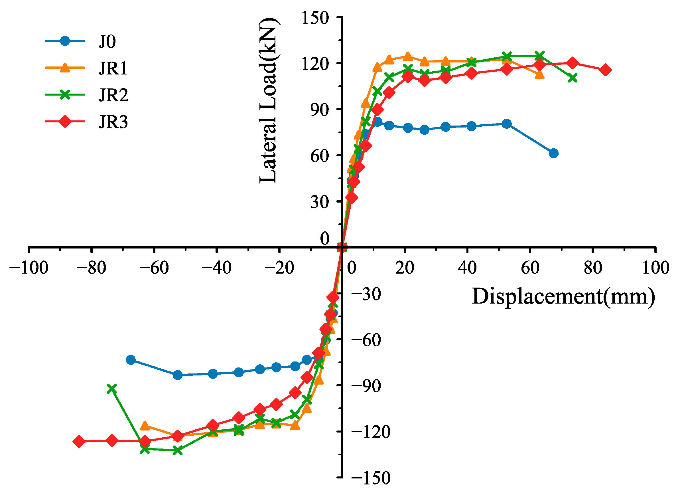
Regardless of the level of seismic damage of the specimen, the strength of the joints retrofitted with appropriate viscoelastic retrofitting methods increased significantly compared to that of the non-damaged joints. Specifically, the yield load and ultimate load of the joints increased by approximately 40%.
(2)
The ultimate deformation of the joint is greatly improved after retrofitting, and the greater the thickness of the viscoelastic pads, the greater the ultimate deformation of the retrofitted joints. The ductility factors of the retrofitted joints decrease, mainly because the yield displacement of the joints after retrofitting is larger than that of the non-damaged joints.
(3)
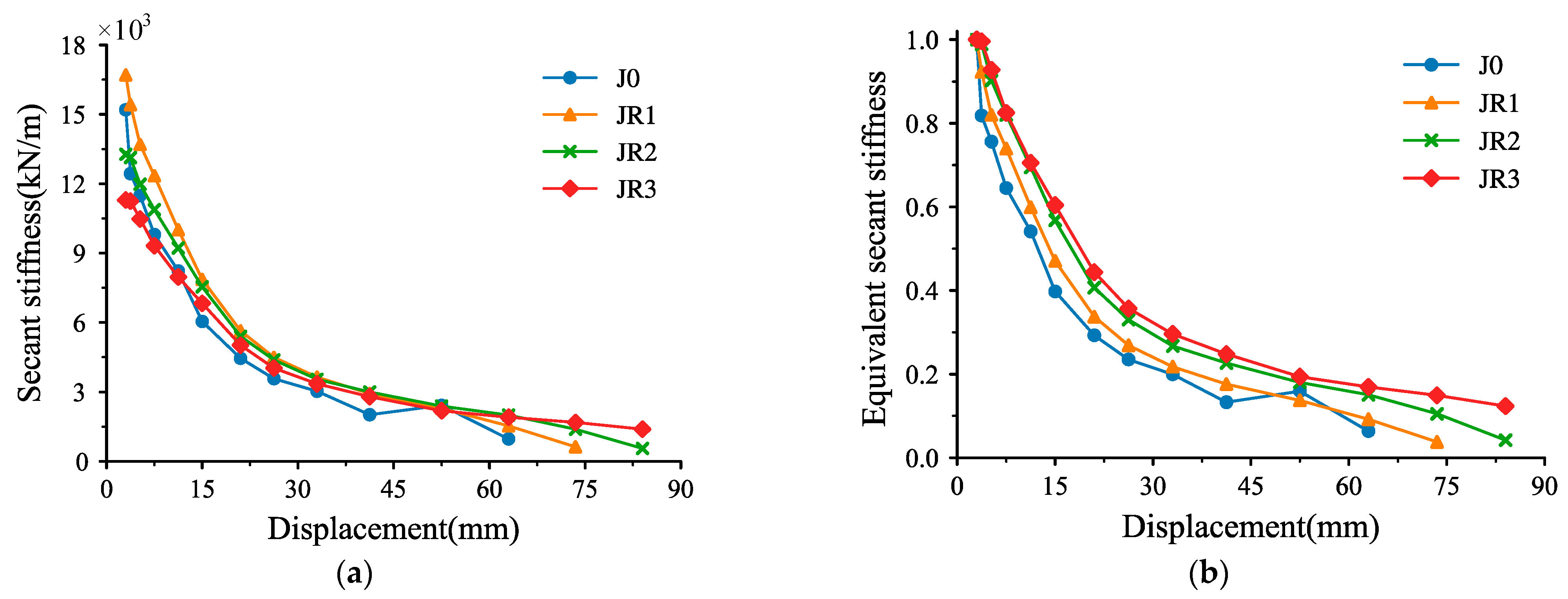
The initial stiffness of the joints retrofitted by the viscoelastic steel-enveloped method is lower, but the stiffness degrades more slowly, and the stiffness at the later stage of loading is higher.
(4)
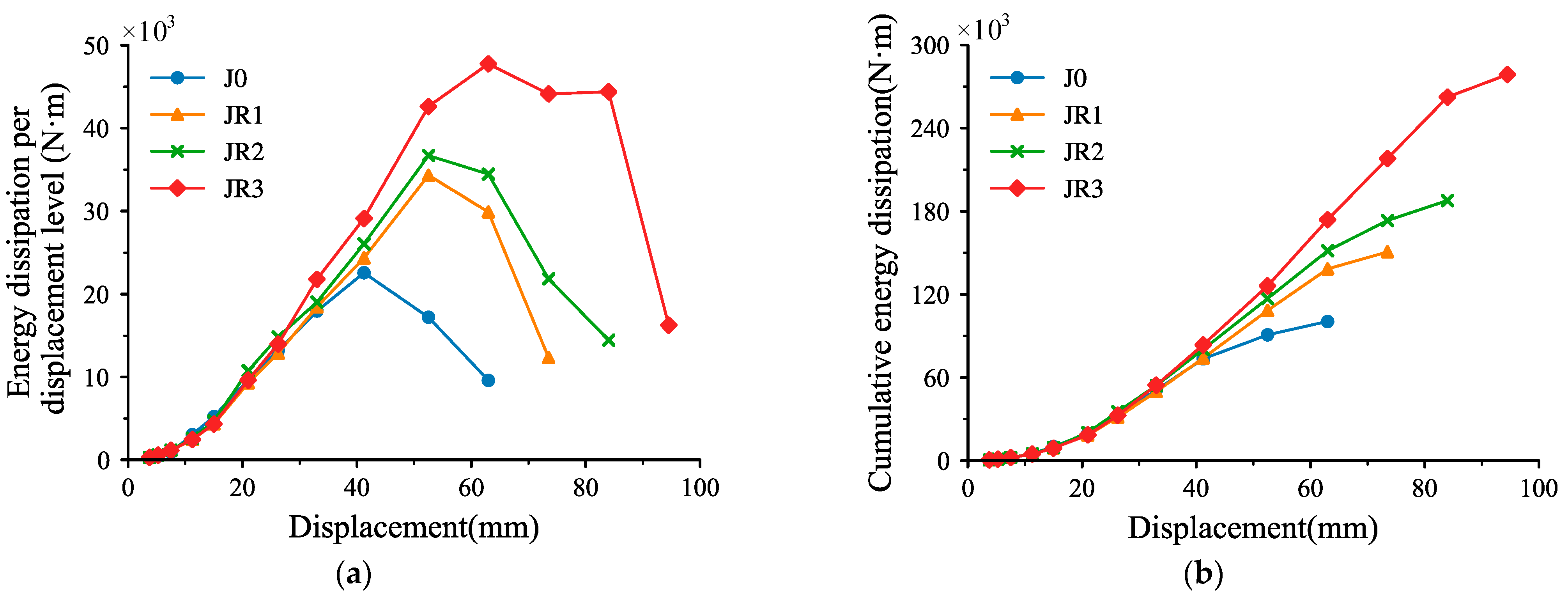
The energy dissipation of the retrofitted joints increases. The thicker the viscoelastic pad is, the more the energy it dissipates.
(5)
In general, the strength of the joints retrofitted by the method proposed in this paper is greatly improved. The viscoelastic steel-enveloped retrofitting method exhibits similar effectiveness to the pure steel-enveloped retrofitting method in terms of strength improvement, but it shows better performance in regards to the ductility and energy dissipation of the retrofitted joints.

Author Contributions

Conceptualization, Z.-D.X.; Methodology, X.-H.H.; Validation, H.-J.X. All authors have read and agreed to the published version of the manuscript.

Funding

This research was funded by National Natural Science Foundation of China (52178463, 52130807), the Shenzhen Sustainable Development Science and Technology Special Project (KCXFZ20211020165543004).

Data Availability Statement

The data presented in this study are available in the respective references.

Conflicts of Interest

The authors declare no conflict of interest.

References

  1. Torabi, A.; Maheri, M.R. Seismic Repair and Retrofit of RC Beam–Column Joints Using Stiffened Steel Plates. Iran. J. Sci. Technol. Trans. Civ. Eng. 2016, 41, 13–26. [Google Scholar] [CrossRef]
  2. Pimanmas, A.; Chaimahawan, P. Shear strength of beam–column joint with enlarged joint area. Eng. Struct. 2010, 32, 2529–2545. [Google Scholar] [CrossRef]
  3. Del Vecchio, C.; Di Ludovico, M.; Balsamo, A.; Prota, A.; Manfredi, G.; Dolce, M. Experimental Investigation of Exterior RC Beam-Column Joints Retrofitted with FRP Systems. J. Compos. Constr. 2014, 18, 04014002. [Google Scholar] [CrossRef]
  4. Biddah, A.; Ghobarah, A.; Aziz, T.S. Upgrading of Nonductile Reinforced Concrete Frame Connections. J. Struct. Eng. 1997, 123, 1001–1010. [Google Scholar] [CrossRef]
  5. Lu, Z.D.; Liu, C.Q.; Zhang, K.C. Experimental Study on the Seismic Performance of Enveloped Steel Strengthened RC Frame Joint. Adv. Eng. Sci. 2010, 42, 56–62. [Google Scholar]
  6. Parvin, A.; Altay, S.; Yalcin, C.; Kaya, O. CFRP Rehabilitation of Concrete Frame Joints with Inadequate Shear and Anchorage Details. J. Compos. Constr. 2010, 14, 72–82. [Google Scholar] [CrossRef]
  7. Akguzel, U.; Pampanin, S. Effects of Variation of Axial Load and Bidirectional Loading on Seismic Performance of GFRP Retrofitted Reinforced Concrete Exterior Beam-Column Joints. J. Compos. Constr. 2010, 14, 94–104. [Google Scholar] [CrossRef]
  8. Yurdakul, O.; Avşar, O. Strengthening of substandard reinforced concrete beam-column joints by external post-tension rods. Eng. Struct. 2016, 107, 9–22. [Google Scholar] [CrossRef]
  9. Cao, Z.M.; Li, A.Q.; Wang, Y.Y.; Yao, Q.L. Experimental study on beam-column connections strengthened with high-strength steel wire mesh and polymer mortar. J. Build. Struct. 2006, 27, 10–15. [Google Scholar]
  10. Tsonos, A.G. Effectiveness of CFRP-jackets and RC-jackets in post-earthquake and pre-earthquake retrofitting of beam–column subassemblages. Eng. Struct. 2008, 30, 777–793. [Google Scholar] [CrossRef]
  11. Wong, D.G.; Zhang, C.; Xia, J.D. Experimental study on earthquake-damaged frame joints strengthened with steel-enveloped plates. China Civ. Eng. J. 2013, 46, 36–45. [Google Scholar]
  12. Faella, C.; Lima, C.; Martinelli, E.; Realfonzo, R. Steel bracing configurations for seismic retrofitting of a reinforced concrete frame. Proc. Inst. Civ. Eng. -Struct. Build. 2014, 167, 54–65. [Google Scholar] [CrossRef]
  13. Zhang, C.; Huang, W.; Zhou, Y.; Luo, W. Experimental and numerical investigation on seismic performance of retrofitted RC frame with sector lead viscoelastic damper. J. Build. Eng. 2021, 44, 103218. [Google Scholar] [CrossRef]
  14. Esmaeeli, E.; He, Y. Cast-in-situ vs prefabricated solution based on NSM-CFRP reinforced SHCC for seismic retrofitting of severely damaged substandard RC beam-column joints. J. Build. Eng. 2021, 43, 103132. [Google Scholar] [CrossRef]
  15. Cai, Z.; Liu, X.; Wu, R.; Li, L.; Lu, Z.; Yu, K. Seismic retrofit of large-scale interior RC beam-column-slab joints after standard fire using steel haunch system. Eng. Struct. 2021, 252, 113585. [Google Scholar] [CrossRef]
  16. Sharma, R.; Bansal, P.P. Behavior of RC exterior beam column joint retrofitted using UHP-HFRC. Constr. Build. Mater. 2019, 195, 376–389. [Google Scholar] [CrossRef]
  17. Zaferani, M.J.; Shariatmadar, H. Repair and retrofitting of external RC beam-to-column joints using the hybrid NSM plus EBR method. Eng. Struct. 2022, 263, 114370. [Google Scholar] [CrossRef]
  18. Dong, Y.-R.; Xu, Z.-D.; Shi, Q.; Li, Q.-Q.; He, Z.-H.; Cheng, Y. Seismic performance and material-level damage evolution of retrofitted RC framed structures by high-performance AVED under different shear-span ratio. J. Build. Eng. 2023, 63, 105495. [Google Scholar] [CrossRef]
  19. Liao, J.H.; Yu, J.T.; Zhang, K.C. Comparative Study on the Strengthening Approach of RC Column-beam Joints Damaged by Simulated Earthquake. Earthq. Resist. Eng. Retrofit. 2011, 33, 98–104. [Google Scholar]
  20. Ge, T.; Xu, Z.D.; Guo, Y.Q.; Huang, X.H.; He, Z.F. Experimental Investigation and Multiscale Modeling of VE Damper Con-sidering Chain Network and Ambient Temperature Influence. J. Eng. Mech. 2022, 148, 04021124. [Google Scholar]
  21. Li, Q.-Q.; Xu, Z.-D.; Dong, Y.-R.; He, Z.-H.; He, J.-X.; Yan, X. Hyperelastic Hybrid Molecular Chain Model of Thermal-Oxidative Aging Viscoelastic Damping Materials Based on Physical–Chemical Process. J. Eng. Mech. 2023, 149, 04022099. [Google Scholar] [CrossRef]
  22. Mahini, S.S.; Ronagh, H.R. Strength and ductility of FRP web-bonded RC beams for the assessment of retrofitted beam–column joints. Compos. Struct. 2010, 92, 1325–1332. [Google Scholar] [CrossRef]
  23. Hawkins, N.M.; Ghosh, S. Acceptance Criteria for Special Precast Concrete Structural Walls Based on Validation Testing. PCI J. 2004, 49, 78–92. [Google Scholar] [CrossRef] [Green Version]
  24. Wu, Z.; Xue, J.; Ke, X.; Sui, Y.; Dong, J. Dynamic experimental and numerical study of double beam–column joints in modern traditional-style steel buildings with viscous damper. Struct. Des. Tall Spéc. Build. 2019, 29, e1677. [Google Scholar] [CrossRef]
  25. Feng, H.; Zhou, F.; Ge, H.; Zhu, H.; Zhou, L. Seismic performance enhancement of buildings using multi-limb brace damper systems. Struct. Des. Tall Spéc. Build. 2020, 30, e1825. [Google Scholar] [CrossRef]
Figure 1. Dimensions and reinforcement details of specimen (unit: mm).
Buildings 13 00702 g001
Figure 2. Schematic view of retrofitted concrete specimens.
Buildings 13 00702 g002
Figure 3. Details of retrofitted concrete specimens.
Buildings 13 00702 g003
Figure 4. Main retrofitting processes on the pre-damage specimens: (a) grinding and cleaning; (b) positioning and welding of steel sleeves; (c) seam sealing; (d) injection of adhesive; (e) glued viscoelastic pads; (f) retrofitted specimens.
Buildings 13 00702 g004
Figure 5. Schematic diagram of test setup.
Buildings 13 00702 g005
Figure 6. Photograph of actual loading.
Buildings 13 00702 g006
Figure 7. The lateral displacement history.
Buildings 13 00702 g007
Figure 8. Failure modes of different specimens. (a) J0; (b) JR1; (c) JR2; (d) JR3.
Buildings 13 00702 g008aBuildings 13 00702 g008b
Figure 9. Hysteresis curves of different beam column joints. (a) J0; (b) JR1; (c) JR2; (d) JR3.
Buildings 13 00702 g009
Figure 10. Energy dissipation of specimens: (a) energy dissipation per displacement level; (b) cumulative energy dissipation.
Buildings 13 00702 g010
Figure 11. Skeleton curves comparison of different specimens in the test.
Buildings 13 00702 g011
Figure 12. Stiffness degradation comparison of secant stiffness and equivalent secant stiffness of different specimens in the test: (a) secant stiffness; (b) equivalent secant stiffness.
Buildings 13 00702 g012
Table 1. The parameters of the specimens.
SpecimensJ0JR1JR2JR3
Thickness of steel/mm/666
Thickness of viscoelastic pad/mm//1018
Degree of damage (drift)/1/501/501/50
Table 2. The mechanical properties of the materials used in the test.
Grade of Concrete 7-Day Compressive Strength/MPa28-Day Compressive Strength/MPaAxial Compressive Strength/MPaYoung’s Modulus/MPa
Concrete C4040.546.7131.2430,205
Grade of Steel BarDiameterYield strength/MPaLimited strength/MPaElongation after break
HRB4008548.63615.730.0713
HRB40016439.12625.610.2658
HRB40018423.33623.510.2560
Steel gradethickness/mmYield strength/MPaLimited strength/MPaYoung’s Modulus/MPa
Q3356362523227,249
Table 3. Loading protocol.
LevelDrift/%Displacement/mmLoading Frequency/HzLoad Cycles
10.2325
20.253.7525
30.355.2525
40.57.525
50.7511.2525
611525
71.42125
81.7526.2525
92.23325
102.7541.2525
113.552.525
124.26325
134.973.525
Table 4. Strength of specimens.
SpecimensLoading DirectionYield Load/kNPeak Load/kNRatio of Yield Load and Peak Load
J0Positive72.3380.531.11
Negative−71.03−83.171.17
JR1Positive108.92124.381.14
Negative−105.78−122.981.16
JR2Positive105.91124.871.18
Negative−108.85−132.371.22
JR3Positive101.18120.141.19
Negative−101.41−126.621.25
Table 5. Calculated results for the ductility of each specimen.
SpecimensLoading DirectionYield Displacement/mmUltimate Displacement/mmRatio of Ultimate Displacement to Comparison SpecimenDuctility FactorMean Ductility Factor
J0Positive7.4752.517.036.99
Negative−7.53−52.56.97
JR1Positive9.89631.206.375.90
Negative−11.59−635.44
JR2Positive12.9373.51.405.685.29
Negative−14.99−73.54.90
JR3Positive15.15841.605.544.85
Negative−20.20−844.16
Disclaimer/Publisher’s Note: The statements, opinions and data contained in all publications are solely those of the individual author(s) and contributor(s) and not of MDPI and/or the editor(s). MDPI and/or the editor(s) disclaim responsibility for any injury to people or property resulting from any ideas, methods, instructions or products referred to in the content.

