
Study on the Effect of Supplementary Cementitious Material on the Regeneration Performance of Waste Fresh Concrete


Abstract
:1. Introduction
2. Materials and Methods
2.1. Materials
2.2. Methods
2.2.1. Proportioning of Concrete
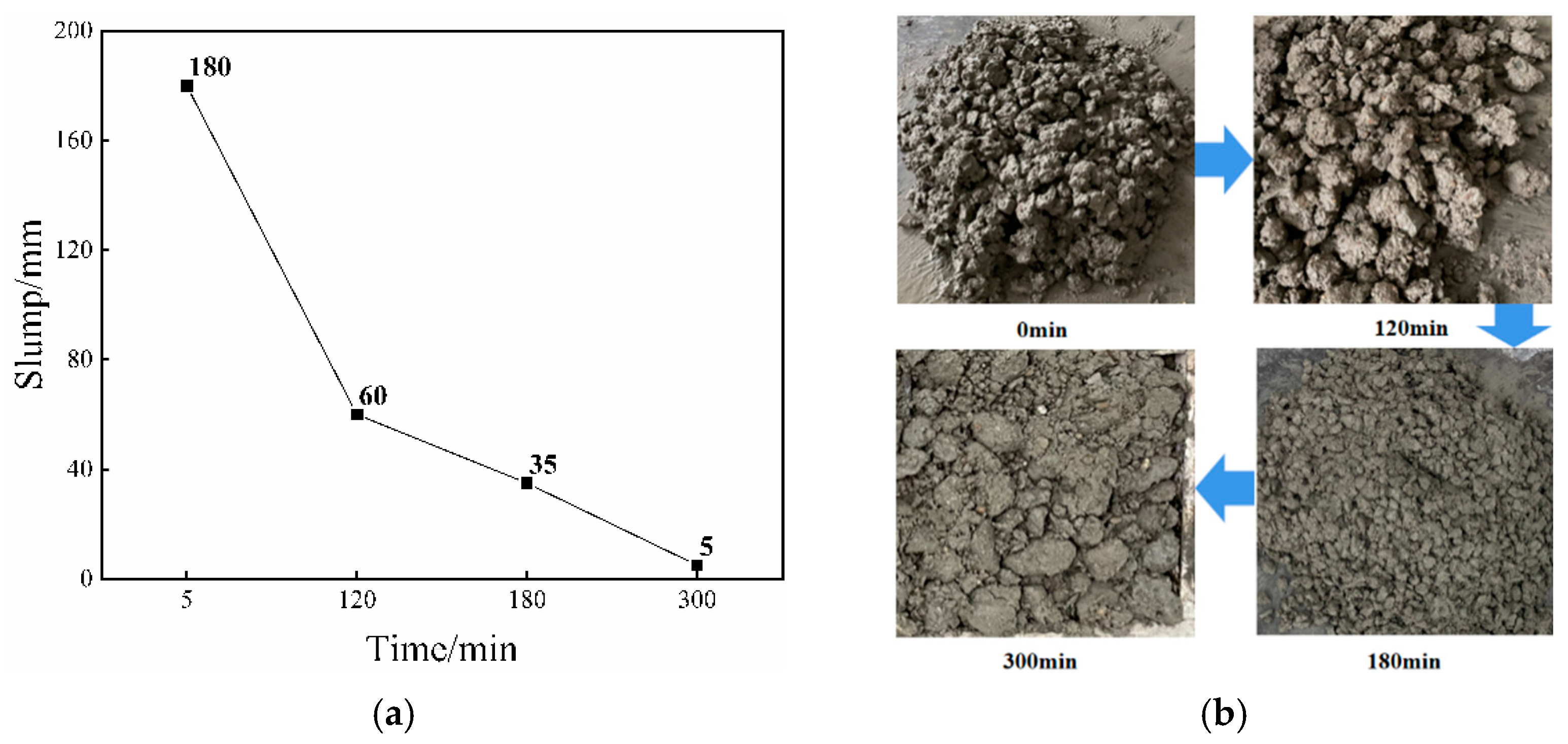
2.2.2. Slump and Mechanical Properties
2.2.3. Freeze–Thaw Resistance
2.2.4. Microstructure Analysis
3. Results
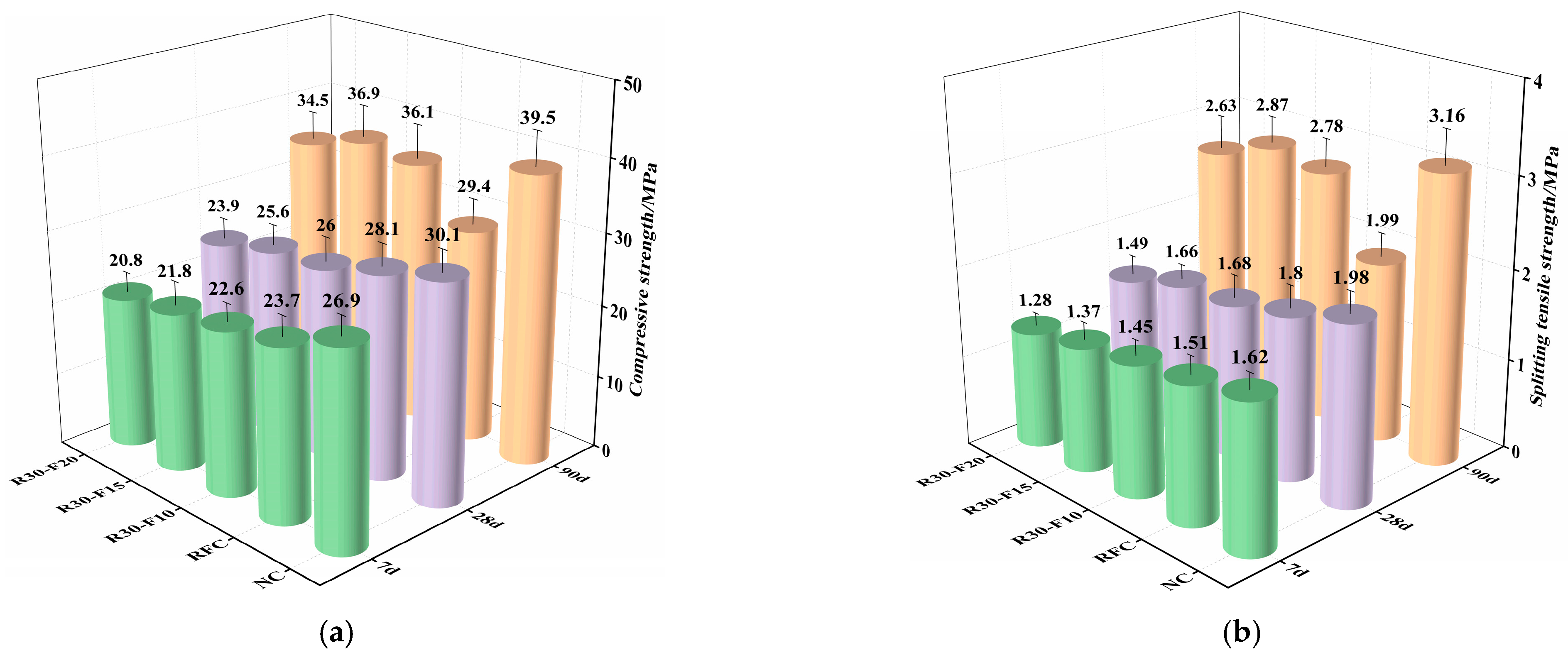
3.1. Mechanical Properties
3.1.1. Effect of Adding Fly Ash Alone
3.1.2. Effect of Composite Addition of Fly Ash and Nano-Silica
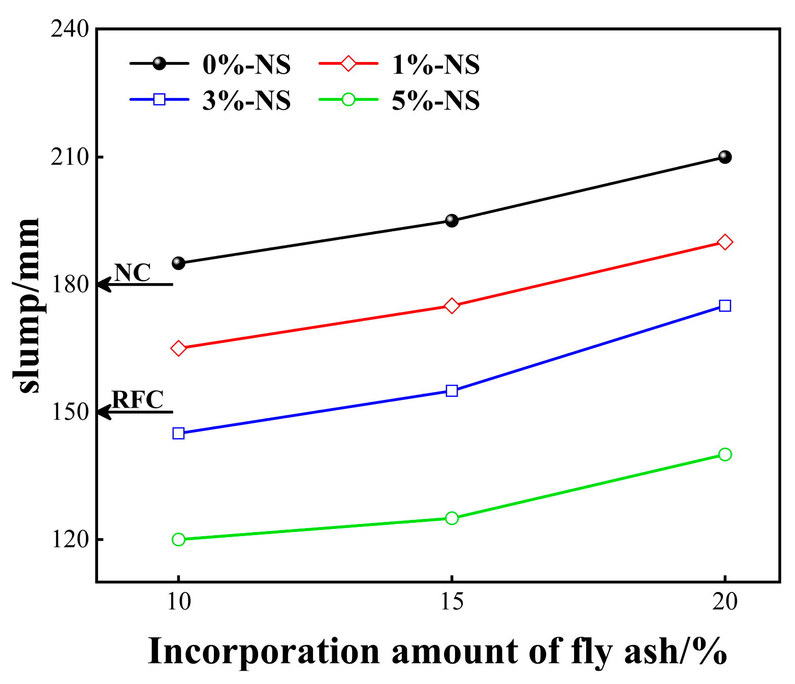
3.2. Slump
3.3. Freeze–Thaw Resistance
3.4. Microstructure Analysis
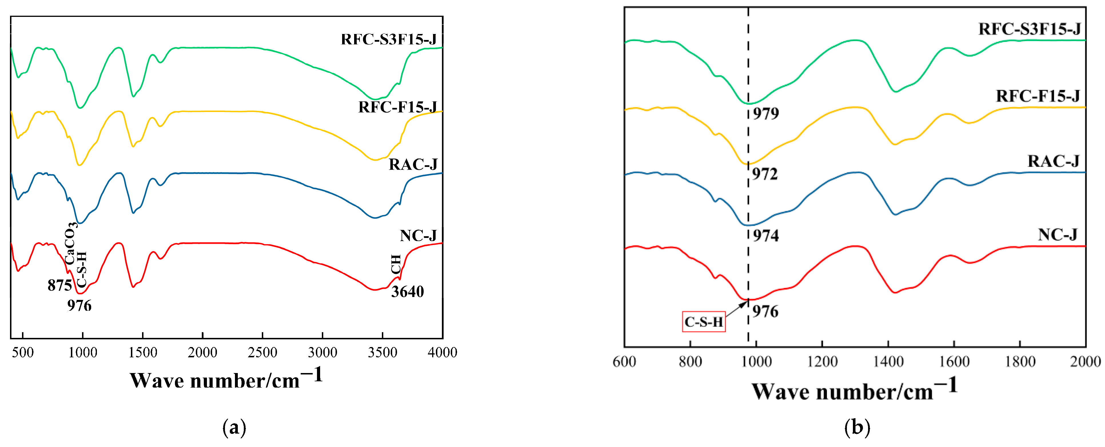
3.4.1. XRD
3.4.2. FTIR
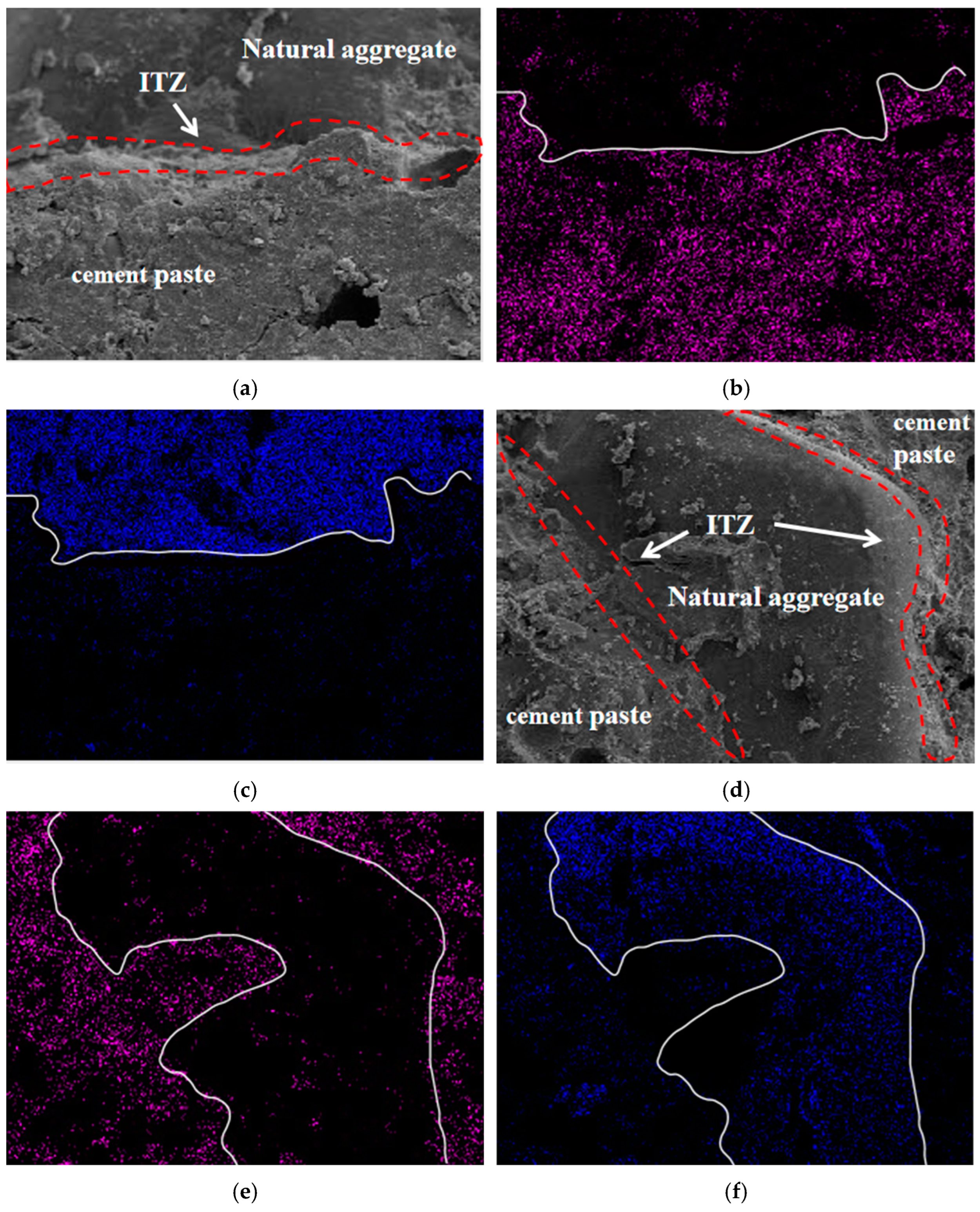
3.4.3. SEM
3.4.4. EDS
4. Discussion
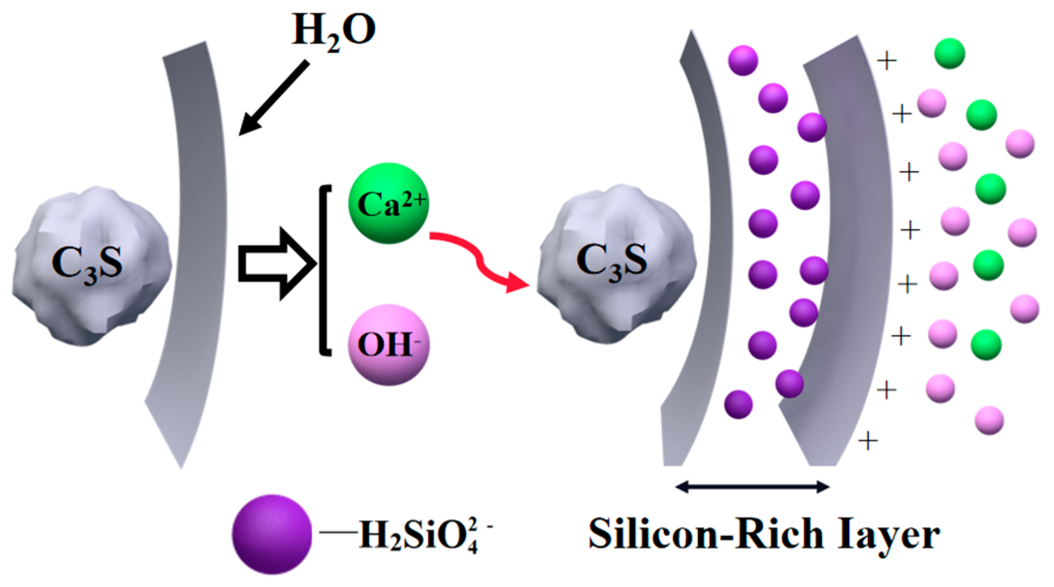
4.1. Effect of Nano-Silica on Hydration and Hardening of RFC
4.2. Effect of Fly Ash on Hydration and Hardening of RFC
5. Conclusions
- (1)
- The early strength of RFC-F added with FA alone is poor. The synergistic effect of FA and NS added together makes the early and late mechanical properties of RFC-SF significantly improved. The compressive strength and splitting tensile strength at 7 d are increased by 15.2% and 20.5% at most, and the compressive strength and splitting tensile strength at 90 d are increased by 50.3% and 76.4% at most.
- (2)
- Adding FA increased the slump of RFC from 150 mm to 185 mm or more; adding NS absorbed free water and reduced the fluidity of concrete. However, the slump of RFC-SF with two materials remains between 120 mm and 185 mm.
- (3)
- The addition of FA alone improved the freeze–thaw performance of RFC-F, and the combined addition of FA and NS further improved the freeze–thaw performance of RFC-SF. Compared with RFC, the mass loss of RFC-F15 and RFC-S3F15 decreased by 31.9% and 42.6% after freeze–thaw cycles.
- (4)
- XRD and FTIR showed that the addition of FA delayed the early hydration process of RFC-F. In contrast, the addition of FA and NS accelerated the hydration degree of RFC-SF, reduced the content of CH in the hydration products, and refined the grain size of CH.
- (5)
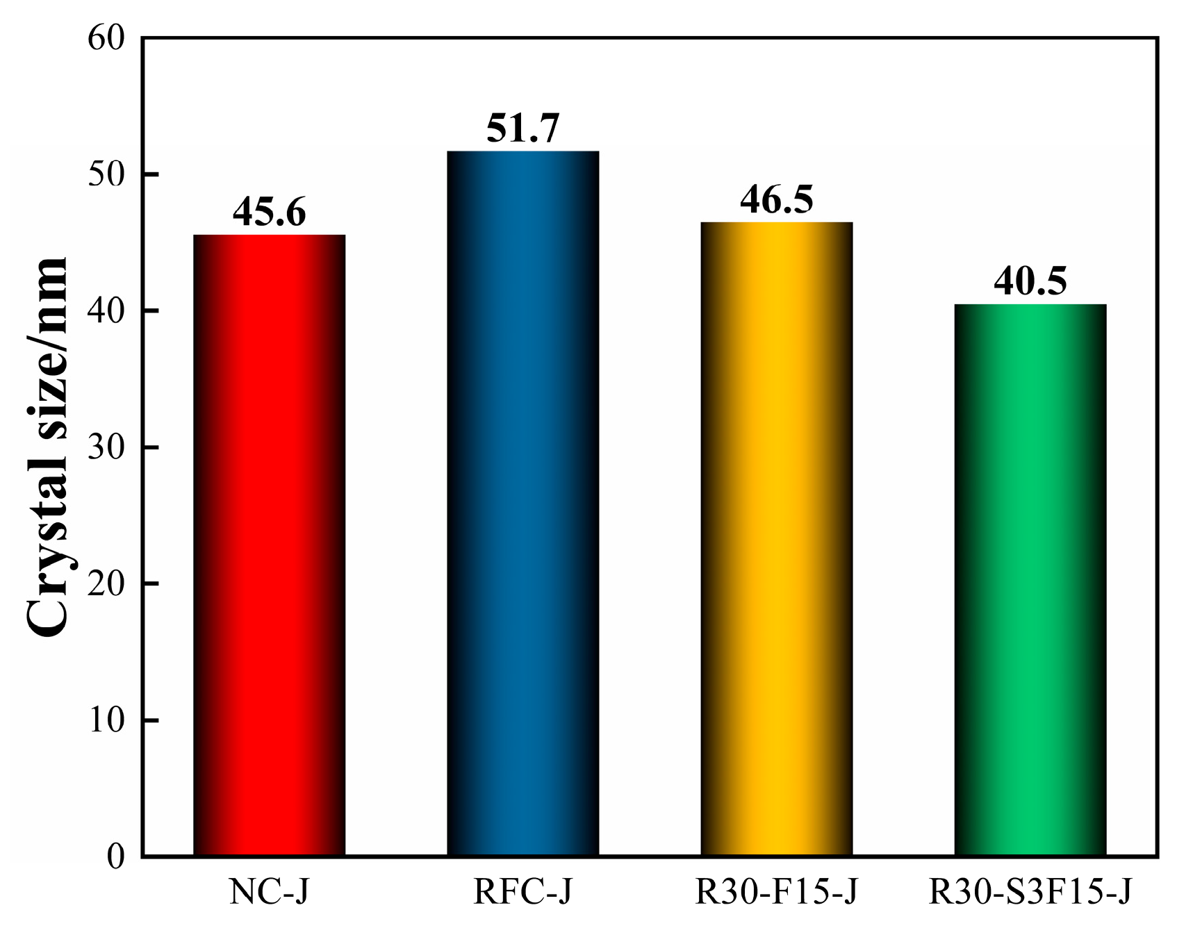
- The results of SEM and EDS indicated that the microstructure of RFC-F15 with FA became denser, and the microstructure of RFC-S3F15 with FA and NS was improved obviously, as some pores were filled with C-S-H. Compared with RFC-J, the Ca/Si ratio of RFC-F15-J and RFC-S3F15-J decreased by 0.39 and 0.91.
- (6)
- As an environmentally friendly material, RFC is conducive to promoting the sustainability of building materials. The effect of more solid wastes such as waste fiber and waste glass on the performance of RFC needs further study, and more efficient recovery methods of WFC need to be actively explored by engineers.
Author Contributions
Funding
Data Availability Statement
Acknowledgments
Conflicts of Interest
References
- Wang, R.X.; Zhang, Y.X. Recycling fresh concrete waste: A review. Struct. Concr. 2018, 19, 1939–1955. [Google Scholar] [CrossRef]
- Silva, D.O.F.; Quattrone, M.; Romano, R.C.O.; Angulo, S.C. Reuse of fines from ready-mix concrete washing slurries. Resour. Conserv. Recycl. 2020, 155, 104653. [Google Scholar] [CrossRef]
- Vieira, L.D.P.; de Figueiredo, A.D.; Moriggi, T.; John, V.M. Waste generation from the production of ready-mixed concrete. Waste Manag. 2019, 94, 146–152. [Google Scholar] [CrossRef] [PubMed]
- Nielsen, C.V.; Glavind, M. Danish experiences with a decade of green concrete. J. Adv. Concert. Technol. 2007, 5, 3–12. [Google Scholar] [CrossRef] [Green Version]
- Zeybek, O.; Ozkilic, Y.O.; Karalar, M.; Celik, A.I.; Qaidi, S.; Ahmad, J.; Burduhos-Nergis, D.D.; Burduhos-Nergis, D.P. Influence of replacing cement with waste glass on mechanical properties of concrete. Materials 2022, 15, 7513. [Google Scholar] [CrossRef] [PubMed]
- Karalar, M.; Bilir, T.; Çavuşlu, M.; Özkiliç, Y.O.; Sabri Sabri, M.M. Use of recycled coal bottom ash in reinforced concrete beams as replacement for aggregate. Front. Mater. 2022, 9, 1064604. [Google Scholar] [CrossRef]
- Qaidi, S.; Najm, H.M.; Abed, S.M.; Ozkilic, Y.O.; Al Dughaishi, H.; Alosta, M.; Sabri, M.M.S.; Alkhatib, F.; Milad, A. Concrete containing waste glass as an environmentally friendly aggregate: A review on fresh and mechanical characteristics. Materials 2022, 15, 6222. [Google Scholar] [CrossRef]
- Celik, A.I.; Ozkilic, Y.O.; Zeybek, O.; Karalar, M.; Qaidi, S.; Ahmad, J.; Burduhos-Nergis, D.D.; Bejinariu, C. Mechanical behavior of crushed waste glass as replacement of aggregates. Materials 2022, 15, 8093. [Google Scholar] [CrossRef]
- Basaran, B.; Kalkan, I.; Aksoylu, C.; Özkılıç, Y.O.; Sabri, M.M.S. Effects of Waste Powder, Fine and Coarse Marble Aggregates on Concrete Compressive Strength. Sustainability 2022, 14, 14388. [Google Scholar] [CrossRef]
- Audo, M.; Mahieux, P.Y.; Turcry, P. Utilization of sludge from ready-mixed concrete plants as a substitute for limestone fillers. Constr. Build. Mater. 2016, 112, 790–799. [Google Scholar] [CrossRef]
- Xuan, D.X.; Poon, C.S.; Zheng, W. Management and sustainable utilization of processing wastes from ready-mixed concrete plants in construction: A review. Resour. Conserv. Recycl. 2018, 136, 238–247. [Google Scholar] [CrossRef]
- He, X.Y.; Ma, Q.H.; Su, Y.; Zheng, Z.Q.; Tan, H.B.; Peng, K.; Zhao, R.X. Humid hardened concrete waste treated by multiple wet-grinding and its reuse in concrete. Constr. Build. Mater. 2022, 350, 128485. [Google Scholar] [CrossRef]
- Vieira, L.D.P.; de Figueiredo, A.D. Evaluation of concrete recycling system efficiency for ready-mix concrete plants. Waste Manag. 2016, 56, 337–351. [Google Scholar] [CrossRef]
- Wang, X.; Yan, Y.R.; Tong, X.F.; Gong, Y.F. Investigation of mineral admixtures on mechanical properties of alkali-activated recycled concrete powders cement. Buildings 2022, 12, 1234. [Google Scholar] [CrossRef]
- Asadollahfardi, G.; Asadi, M.; Jafari, H.; Moradi, A.; Asadollahfardi, R. Experimental and statistical studies of using wash water from ready-mix concrete trucks and a batching plant in the production of fresh concrete. Constr. Build. Mater. 2015, 98, 305–314. [Google Scholar] [CrossRef]
- Reiterman, P.; Mondschein, P.; Doušová, B.; Davidová, V.; Keppert, M. Utilization of concrete slurry waste for soil stabilization. Case Stud. Constr. Mater. 2022, 16, e00900. [Google Scholar] [CrossRef]
- Zhang, J.; Fujiwara, T. Concrete sludge powder for soil stabilization. Transp. Res. Rec. J. Transp. Res. Board 2007, 2026, 54–59. [Google Scholar] [CrossRef]
- Iizuka, A.; Sakai, Y.; Yamasaki, A.; Honma, M.; Hayakawa, Y.; Yanagisawa, Y. Bench-scale operation of a concrete sludge recycling plant. Ind. Eng. Chem. Res. 2012, 51, 6099–6104. [Google Scholar] [CrossRef]
- Iizuka, A.; Sasaki, T.; Hongo, T.; Honma, M.; Hayakawa, Y.; Yamasaki, A.; Yanagisawa, Y. Phosphorus adsorbent derived from concrete sludge (PAdeCS) and its phosphorus recovery performance. Ind. Eng. Chem. Res. 2012, 51, 11266–11273. [Google Scholar] [CrossRef]
- Sasaki, T.; Sakai, Y.; Iizuka, A.; Nakae, T.; Kato, S.; Kojima, T.; Yamasaki, A. Evaluation of the capacity of hydroxyapaptite prepared from concrete sludge to remove lead from water. Ind. Eng. Chem. Res. 2011, 50, 9564–9568. [Google Scholar] [CrossRef]
- Xuan, D.X.; Zhan, B.J.; Poon, C.S.; Zheng, W. Innovative reuse of concrete slurry waste from ready-mixed concrete plants in construction products. J. Hazard. Mater. 2016, 312, 65–72. [Google Scholar] [CrossRef] [PubMed]
- Lobo, C.; Guthrie, W.F.; Kacker, R. A Study on the reuse of plastic concrete using extended set-retarding admixtures. J. Res. Natl. Inst. Stand. Technol. 1995, 100, 575–589. [Google Scholar] [CrossRef] [PubMed]
- Okawa, Y.; Yamamiya, H.; Nishibayashi, S. Study on the reuse of returned concrete. Mag. Concr. Res. 2000, 52, 109–115. [Google Scholar] [CrossRef]
- Vieira, L.D.P.; Figueiredo, A.D. Implementation of the use of hydration stabilizer admixtures at a ready-mix concrete plant. Case Stud. Constr. Mater. 2020, 12, e00334. [Google Scholar] [CrossRef]
- Kong, D.Y.; He, G.P.; Pan, H.W.; Weng, Y.H.; Du, N.; Sheng, J.S. Influences and mechanisms of nano-C-S-H gel addition on fresh properties of the cement-based materials with sucrose as retarder. Materials 2020, 13, 2345. [Google Scholar] [CrossRef]
- Lothenbach, B.; Scrivener, K.; Hooton, R.D. Supplementary cementitious materials. Cem. Concr. Res. 2011, 41, 1244–1256. [Google Scholar] [CrossRef]
- Wang, B.; Xiao, H.; Zhang, T. Autogenous shrinkage property of high-performance multi-walled cement-based carbon nanotubes composites. J. Nanosci. Nanotechnol. 2018, 18, 6894–6904. [Google Scholar] [CrossRef]
- Gholampour, A.; Kiamahalleh, M.V.; Tran, D.N.H.; Ozbakkaloglu, T.; Losic, D. Revealing the dependence of the physiochemical and mechanical properties of cement composites on graphene oxide concentration. RSC Adv. 2017, 7, 55148–55156. [Google Scholar] [CrossRef] [Green Version]
- Hasan-Nattaj, F.; Nematzadeh, M. The effect of forta-ferro and steel fibers on mechanical properties of high-strength concrete with and without silica fume and nano-silica. Constr. Build. Mater. 2017, 137, 557–572. [Google Scholar] [CrossRef]
- Wang, J.B.; Du, P.; Zhou, Z.H.; Xu, D.Y.; Xie, N.; Cheng, X. Effect of nano-silica on hydration, microstructure of alkali-activated slag. Constr. Build. Mater. 2019, 220, 110–118. [Google Scholar] [CrossRef]
- Shan, H.L.; Yu, Z.P. Strength, chloride ion penetration, and nanoscale characteristics of concrete prepared with nano-silica slurry pre-coated recycled aggregate. Buildings 2022, 12, 1707. [Google Scholar] [CrossRef]
- Kong, D.Y.; Su, Y.; Du, X.F.; Yang, Y.; Wei, S.; Shah, S.P. Influence of nano-silica agglomeration on fresh properties of cement pastes. Constr. Build. Mater. 2013, 43, 557–562. [Google Scholar] [CrossRef]
- Elahi, A.; Basheer, P.A.M.; Nanukuttan, S.V.; Khan, Q.U.Z. Mechanical and durability properties of high performance concretes containing supplementary cementitious materials. Constr. Build. Mater. 2010, 24, 292–299. [Google Scholar] [CrossRef]
- Kim, K.; Shin, M.; Cha, S. Combined effects of recycled aggregate and fly ash towards concrete sustainability. Constr. Build. Mater. 2013, 48, 499–507. [Google Scholar] [CrossRef]
- Yoshitake, I.; Zhang, W.B.; Mimura, Y.; Saito, T. Uniaxial tensile strength and tensile Young’s modulus of fly-ash concrete at early age. Constr. Build. Mater. 2013, 40, 514–521. [Google Scholar] [CrossRef]
- Cui, K.; Chang, J. Hydration, reinforcing mechanism, and macro performance of multi-layer graphene-modified cement composites. J. Build. Eng. 2022, 57, 104880. [Google Scholar] [CrossRef]
- Gebremichael, N.N.; Karein, S.M.M.; Karakouzian, M.; Jadidi, K. Investigation of setting time and compressive strength of ready-mixed concrete blended with returned fresh concrete. Constr. Build. Mater. 2019, 197, 428–435. [Google Scholar] [CrossRef] [Green Version]
- Feng, P.; Chang, H.L.; Liu, X.; Ye, S.X.; Shu, X.; Ran, Q.P. The significance of dispersion of nano-SiO2 on early age hydration of cement pastes. Mater. Des. 2020, 186, 108320. [Google Scholar] [CrossRef]
- Reches, Y.; Thomson, K.; Helbing, M.; Kosson, D.S.; Sanchez, F. Agglomeration and reactivity of nanoparticles of SiO2, TiO2, Al2O3, Fe2O3, and clays in cement pastes and effects on compressive strength at ambient and elevated temperatures. Constr. Build. Mater. 2018, 167, 860–873. [Google Scholar] [CrossRef]
- Wang, J.B.; Liu, M.L.; Wang, Y.G.; Zhou, Z.H.; Xu, D.Y.; Du, P.; Cheng, X. Synergistic effects of nano-silica and fly ash on properties of cement-based composites. Constr. Build. Mater. 2020, 262, 120737. [Google Scholar] [CrossRef]
- Sun, H.L.; Zhang, X.Z.; Zhao, P.; Liu, D. Effects of nano-Silica particle size on fresh state properties of cement paste. KSCE J. Civ. Eng. 2021, 25, 2555–2566. [Google Scholar] [CrossRef]
- Zhou, S.; Zhang, X.T.; Zhou, H.; Li, D.X. Effects of graphene oxide encapsulated silica fume and its mixing with nano-silica sol on properties of fly ash-mixed cement composites. Crystals 2022, 12, 144. [Google Scholar] [CrossRef]
- Taylor, H.F.W.; Newbury, D.E. An electron-microprobe study of a mature cement paste. Cem. Concr. Res. 1984, 14, 565–573. [Google Scholar] [CrossRef]
- Singh, L.P.; Karade, S.R.; Bhattacharyya, S.K.; Yousuf, M.M.; Ahalawat, S. Beneficial role of nanosilica in cement based materials—A review. Constr. Build. Mater. 2013, 47, 1069–1077. [Google Scholar] [CrossRef]
- Bilir, T.; Gencel, O.; Topcu, I.B. Properties of mortars with fly ash as fine aggregate. Constr. Build. Mater. 2015, 93, 782–789. [Google Scholar] [CrossRef]


| Materials | SiO2 | Al2O3 | CaO | Fe2O3 | MgO | K2O | Na2O | Cr2O3 | Others |
|---|---|---|---|---|---|---|---|---|---|
| cement | 31.5 | 10.7 | 46.19 | 3.93 | 3.31 | 1.31 | 0.76 | / | 2.3 |
| fly ash | 40.1 | 29.3 | 3.69 | 14.9 | 0.81 | 1.13 | 0.58 | 5.94 | 3.55 |
| Exterior | Average Particle Size/nm | Content/% | Solvent | pH Value |
|---|---|---|---|---|
| Transparent liquid | 15 ± 5 | 30 | Transparent liquid | 9–11 |
| Samples | Cement Paste | Aggregate | WFC | ||||||
|---|---|---|---|---|---|---|---|---|---|
| Cement | Water | FA | NS | PS | Additional Water | Sand | Gravel | ||
| NC | 360 | 180 | - | - | 2.5 | - | 760 | 1100 | - |
| RFC | 252 | 126 | - | - | 1.8 | - | 532 | 770 | 720.7 |
| RFC-F10 | 216 | 126 | 36 | - | 1.8 | - | 532 | 770 | 720.7 |
| RFC-F15 | 198 | 126 | 54 | - | 1.8 | - | 532 | 770 | 720.7 |
| RFC-F20 | 180 | 126 | 72 | - | 1.8 | - | 532 | 770 | 720.7 |
| RFC-S1F10 | 214.9 | 123.5 | 36 | 3.6 | 1.8 | 2.5 | 532 | 770 | 720.7 |
| RFC-S3F10 | 212.8 | 118.4 | 36 | 10.8 | 1.8 | 7.6 | 532 | 770 | 720.7 |
| RFC-S5F10 | 210.6 | 113.4 | 36 | 18 | 1.8 | 12.6 | 532 | 770 | 720.7 |
| RFC-S1F15 | 196.9 | 123.5 | 54 | 3.6 | 1.8 | 2.5 | 532 | 770 | 720.7 |
| RFC-S3F15 | 194.8 | 118.4 | 54 | 10.8 | 1.8 | 7.6 | 532 | 770 | 720.7 |
| RFC-S5F15 | 192.6 | 113.4 | 54 | 18 | 1.8 | 12.6 | 532 | 770 | 720.7 |
| RFC-S1F20 | 178.9 | 123.5 | 72 | 3.6 | 1.8 | 2.5 | 532 | 770 | 720.7 |
| RFC-S3F20 | 176.8 | 118.4 | 72 | 10.8 | 1.8 | 7.6 | 532 | 770 | 720.7 |
| RFC-S5F20 | 174.6 | 113.4 | 72 | 18 | 1.8 | 12.6 | 532 | 770 | 720.7 |
Disclaimer/Publisher’s Note: The statements, opinions and data contained in all publications are solely those of the individual author(s) and contributor(s) and not of MDPI and/or the editor(s). MDPI and/or the editor(s) disclaim responsibility for any injury to people or property resulting from any ideas, methods, instructions or products referred to in the content. |
© 2023 by the authors. Licensee MDPI, Basel, Switzerland. This article is an open access article distributed under the terms and conditions of the Creative Commons Attribution (CC BY) license (https://creativecommons.org/licenses/by/4.0/).
Share and Cite
Wang, W.; Zhang, D.; Liu, L.; Zhang, X.; Wang, Y. Study on the Effect of Supplementary Cementitious Material on the Regeneration Performance of Waste Fresh Concrete. Buildings 2023, 13, 687. https://doi.org/10.3390/buildings13030687
Wang W, Zhang D, Liu L, Zhang X, Wang Y. Study on the Effect of Supplementary Cementitious Material on the Regeneration Performance of Waste Fresh Concrete. Buildings. 2023; 13(3):687. https://doi.org/10.3390/buildings13030687
Chicago/Turabian StyleWang, Weicheng, Daoming Zhang, Linqing Liu, Xueyuan Zhang, and Yue Wang. 2023. "Study on the Effect of Supplementary Cementitious Material on the Regeneration Performance of Waste Fresh Concrete" Buildings 13, no. 3: 687. https://doi.org/10.3390/buildings13030687