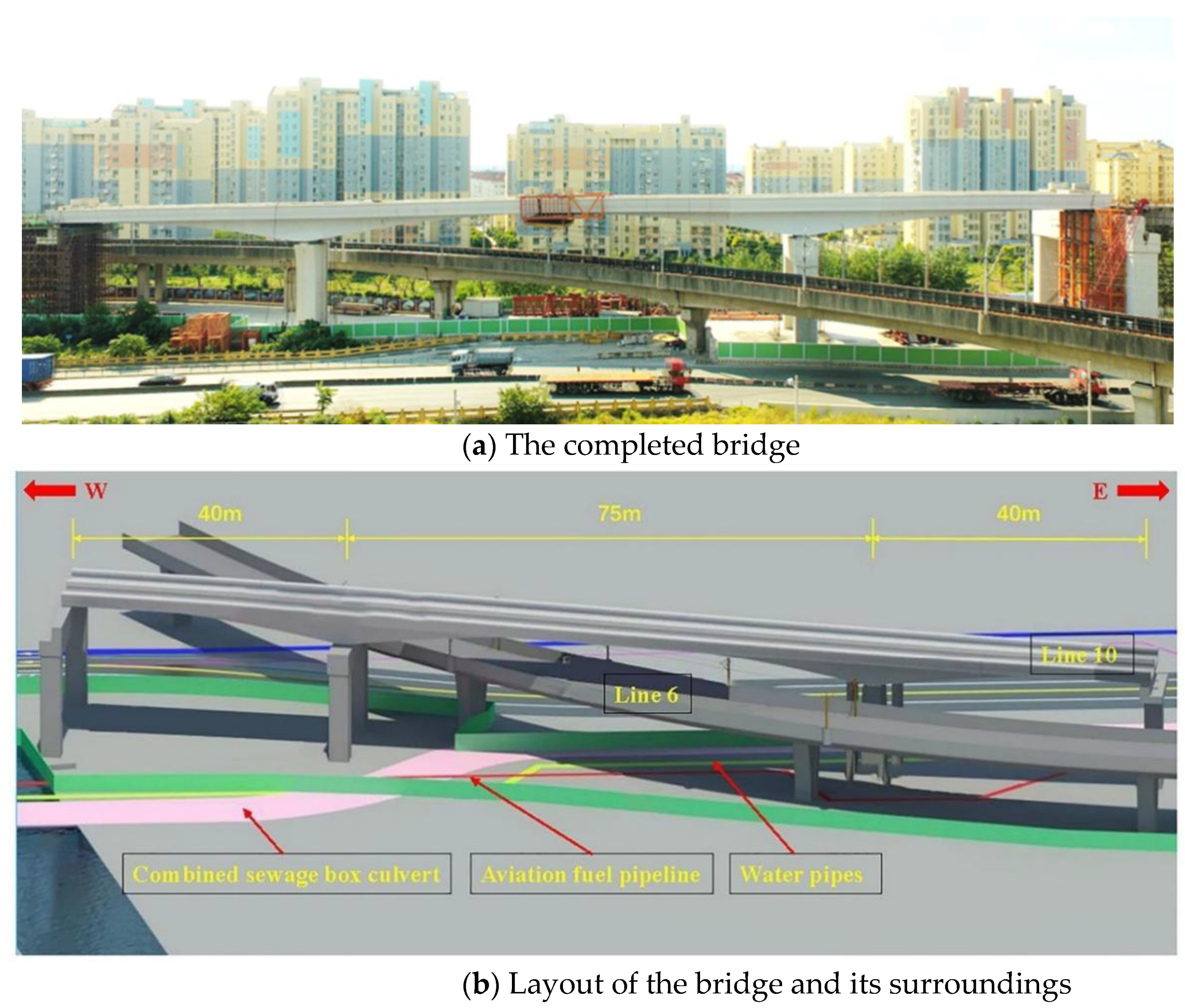
2. General Description of the Constructed Bridge
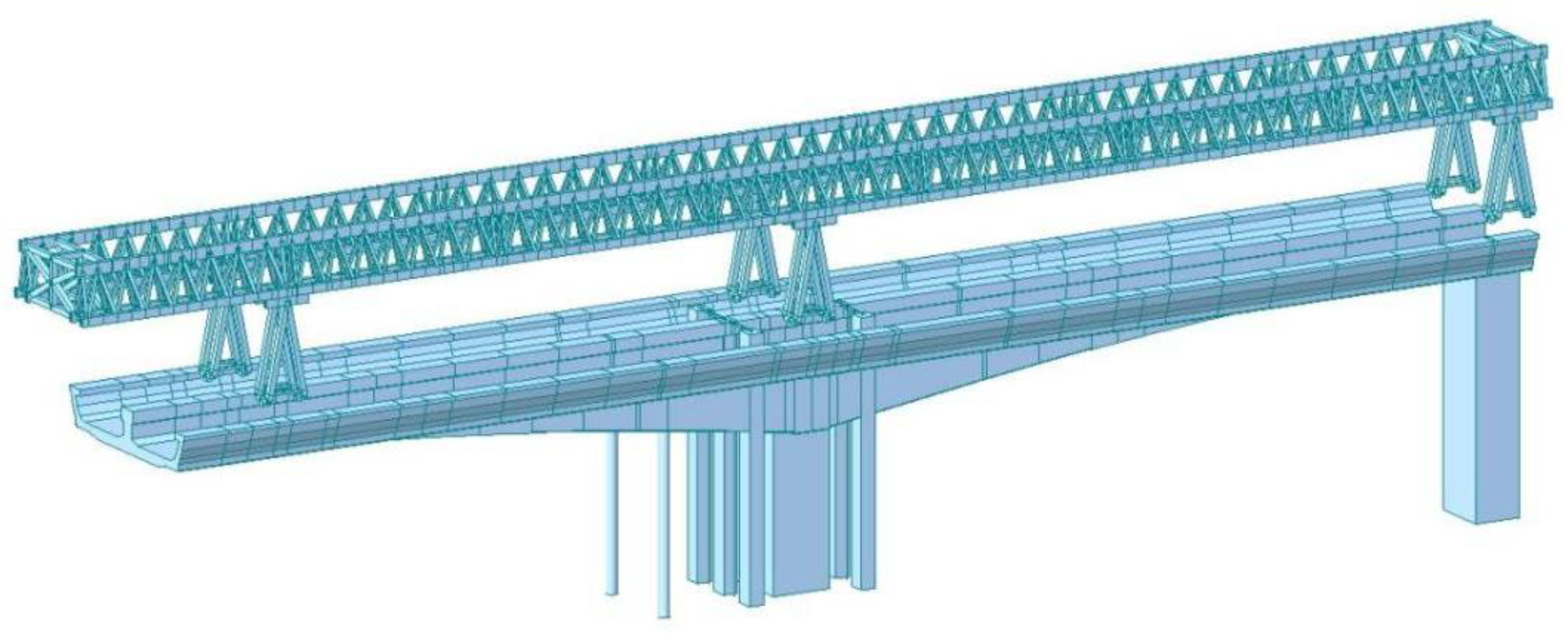
Figure 1a illustrates the completed bridge after construction. The constructed continuous bridge span is 40 + 75 + 40 m, as shown in
Figure 1b. It is a pre-stressed U-shape concrete continuous beam.
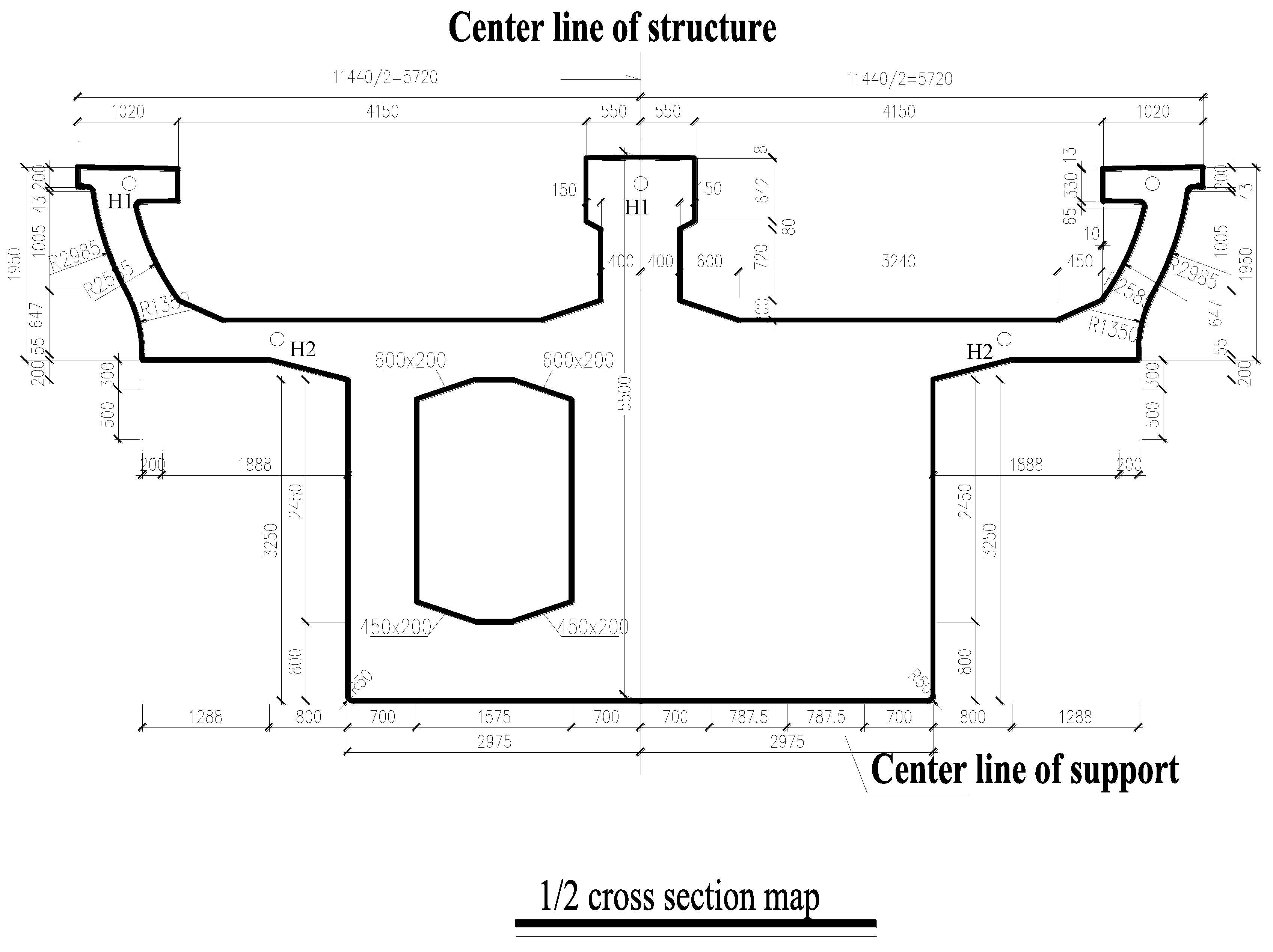
Figure 2 presents the cross section of the U-shaped single-box double-cell concrete box beams. The constructed project is located in a complex environment. Metro Line 6 passes diagonally across the constructed bridge [
13]. Therefore, the prefabricated beam section cannot be lifted vertically in the mid-span. The underground pipelines on both sides also limit the parking spaces for large construction equipment. The heavy traffic volume and people stream near the construction site also limit the other construction method. Therefore, the conventional construction technology cannot be applied. Consequently, the novel asymmetric loading cantilever assembling technology for the bridge erection machine [
14,
15,
16] is developed and applied.
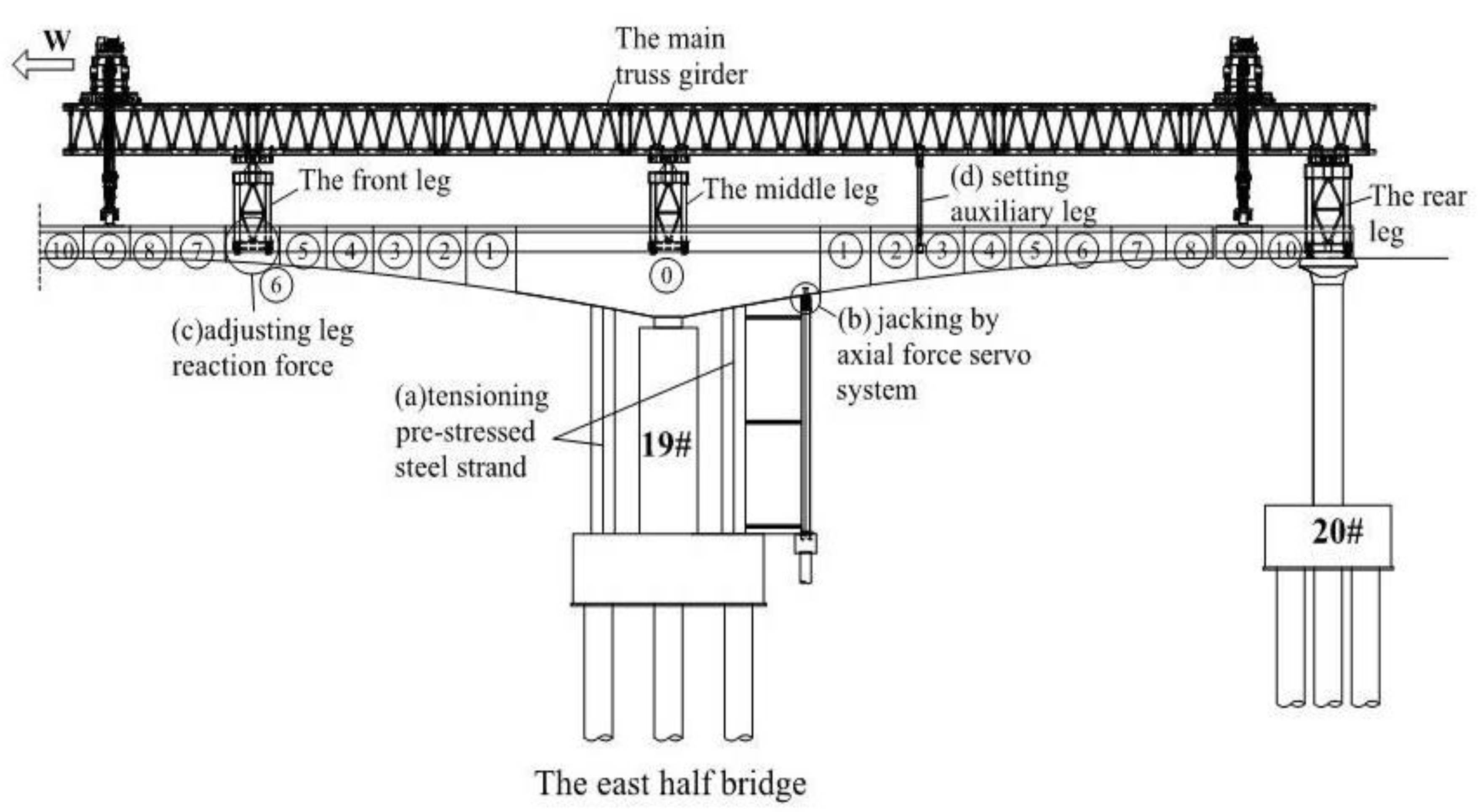
The bridge is divided into 40 sections, as shown in
Figure 3. Sections 0#~10# of the side-span to sections 0#~10# of the mid-span exist in the eastern half of the bridge. The same applies for the western half of the bridge. The pier numbers for the eastern half of the bridge and the western half of bridge are 19# and 18#, respectively. Both the 0# and 10# sections are cast in place, while the remaining sections are all pre-cast sections. During the construction process, the eastern half of the bridge is first constructed into a T-shape structure. The bridge erection machine is then erected on the T-shape structure. Sections 1#~9# are lifted in sequence by the bridge erection machine. After the completion of the eastern half of the bridge, the bridge erection machine moves to the western half of the bridge on the beam, which is referred to as the pass-hole stage. Similarly, the construction of the western half of the bridge is completed. Finally, the construction of the eastern half and the western half is closed. As the bridge erection machine should assist the bridge construction on the T-structure, the bending moment of the beam caused by the leg load should be adjusted in balance using the mechanical state control method.
3. Mechanical State Control Technology
Figure 3 presents the four mechanical state control methods used in the bridge construction process: (a) tensioning the pre-stressed steel strand, (b) jacking by the axial force servo system, (c) adjusting the leg reaction force, and (d) setting the auxiliary leg. During the pre-cast assembly construction of the bridge, the four mechanical state control methods are well coordinated in order to jointly adjust the imbalanced moment of the T-shape structure.
Tensioning the pre-stressed steel strand and setting the auxiliary leg play an important role in the pre-hoisting stage, as shown in
Figure 3. The pre-stressed tensile steel strands of the side-span of section 0# are first tensioned. Simultaneously, the auxiliary legs are installed and used to erect and assemble the bridge erection machine on the T-shape structure.
The axial force servo system control and adjusting the leg reaction force play a vital role in the lifting stage. When the leg reaction force exceeds the limit value, the axial force servo system is turned on in order to provide the upward force to balance the bending moment caused by the front leg force on the T-shape structure.
The auxiliary leg control and the leg reaction force load control play an important role in the hole-passing stage. When the bridge erection machine passes through the hole, the auxiliary legs are installed. During the hole-passing stage, the front leg reaction load is monitored in real time. When the leg reaction force exceeds 270 tons, the height of the legs is adjusted to reduce the leg reaction force so that the dynamic moment balance state of the T-shape structure can be performed.
A computational model is built for two segments in the hoisting process. In the process of segment lifting, the forces of the structure under different processes are calculated. According to the calculated results of different working conditions, the tension time and size of the tensile beam and the jacking force and the jacking time of the servo system are determined.
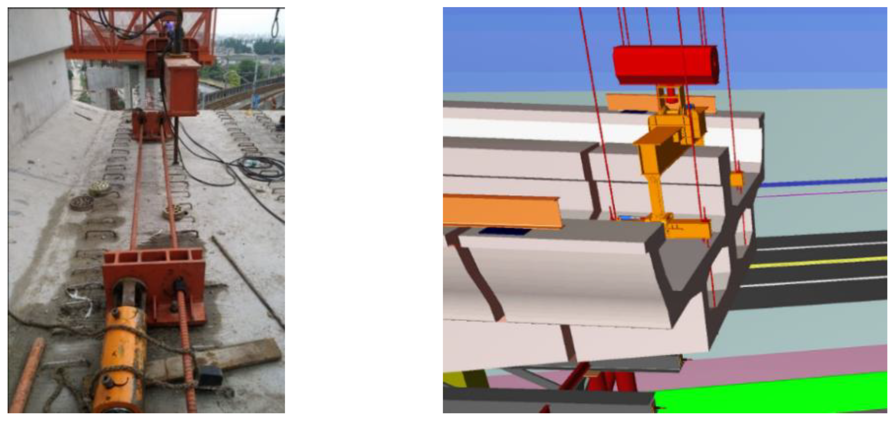
3.1. Tension Pre-Stressed Steel Strand
During the construction stage, the front legs of the bridge erector gradually move to the mid-span as the beam sections are erected. If the mechanical posture of the T-shape structure is not adjusted, it causes the imbalance and instability of the T-shape structure. Therefore, by tensioning vertical pre-stressed steel strands, the mechanical state of the structure can be roughly adjusted within a certain range, as shown in
Figure 3.
Before lifting section 1#, the front legs erected on section 0# produce an eccentric load on the T-shape structure. Therefore, the side-span tensile strands are first pre-tensioned with 50 tons. As the construction process continues, the front legs move forward along the cantilever of the T-shape structure. The pre-tensioned 50 ton force will no longer be sufficient to balance the increasing eccentric load. Therefore, when section 3# is lifted by the crane and transported between the front leg and the middle leg, the tensile steel strands of the side-span are tensioned with a force of 300 tons.
When hoisting section 10# of the bridge, only the side-span should be hoisted, while the mid-span does not need to be hoisted. The eccentric load caused by section 10# of the side-span is greater than that caused by the front leg of the bridge erection machine. Therefore, the mid-span tensile steel strand is stretched to 300 tons in order to offset the unbalanced moment caused by this eccentric load.
When the bridge erection machine passes through the hole, each leg is transported to the western half of the bridge. Therefore, the tensile strands on both sides of the T-shape structure are also unloaded step by step in order to achieve the mechanical state control effect.
3.2. Axial Force Servo System
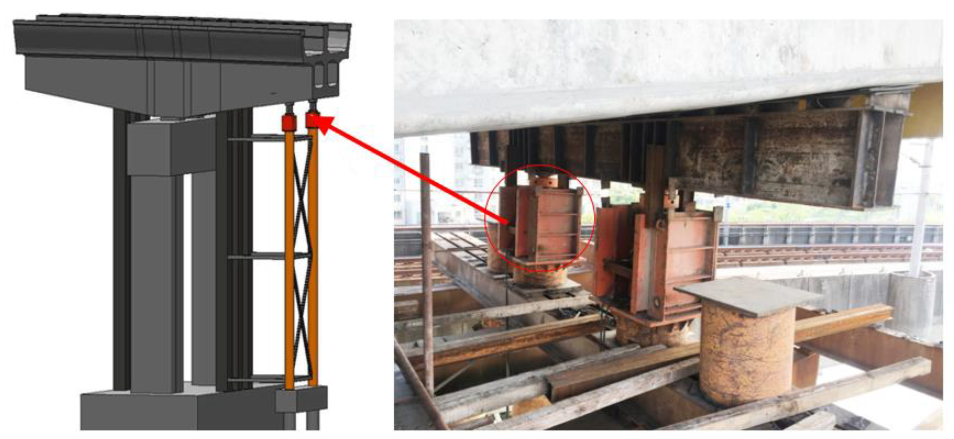
The pre-stressing steel strand can provide a static equilibrium moment. However, the tensile force of the strand can only be roughly adjusted. The unbalanced moment during the construction process is dynamically changed. Therefore, the tensile steel strand can only roughly balance the end moment of the T-shape structure caused by the front leg. The axial force automatic servo system is then used to elaborately control the beam moment. The asymmetric load introduced by the front leg of the bridge erection machine is balanced by pre-stressing the steel strand and the control force of the axial force servo system.
Figure 4 presents the axial force automatic servo system, which applies an upward active control force to hoist section 1#. Consequently, it can make up for the insufficient balance moment provided by the tensile steel strand in order to perform the dynamic moment balance. The required active control force can be accurately set, according to the specific value that the balance moment should compensate. Due to the adjustment of the axial force automatic servo system, the upside surface compressive stress of the developed T-shape structure induced by the bridge erection machine leg load is reduced during the beam section lifting; tensile stress may even appear. Therefore, it is necessary to use the servo system in order to actively provide an upward counterforce. The beam section will then have a reserved pre-stress, which can balance the tensile load stress caused by the front leg. The refined dynamic control of the unbalanced moment is performed by providing an active controlled and continuously changing force to the T-shape structure.
In the pre-hoisting stage, the front leg reaction force is monitored in real time. The axial force automatic servo system first applies an initial axial force of 70 tons. When the leg reaction force approaches 200 tons, the axial force automatic servo system applies an initial axial force of 125 tons. During the hoisting of section 2#, when the leg reaction force is close to 200 tons, the axial force automatic servo system applies an initial axial force of 100 tons and the subsequent construction stage is adjusted according to the specific construction situation.
3.3. Reaction Leg Force
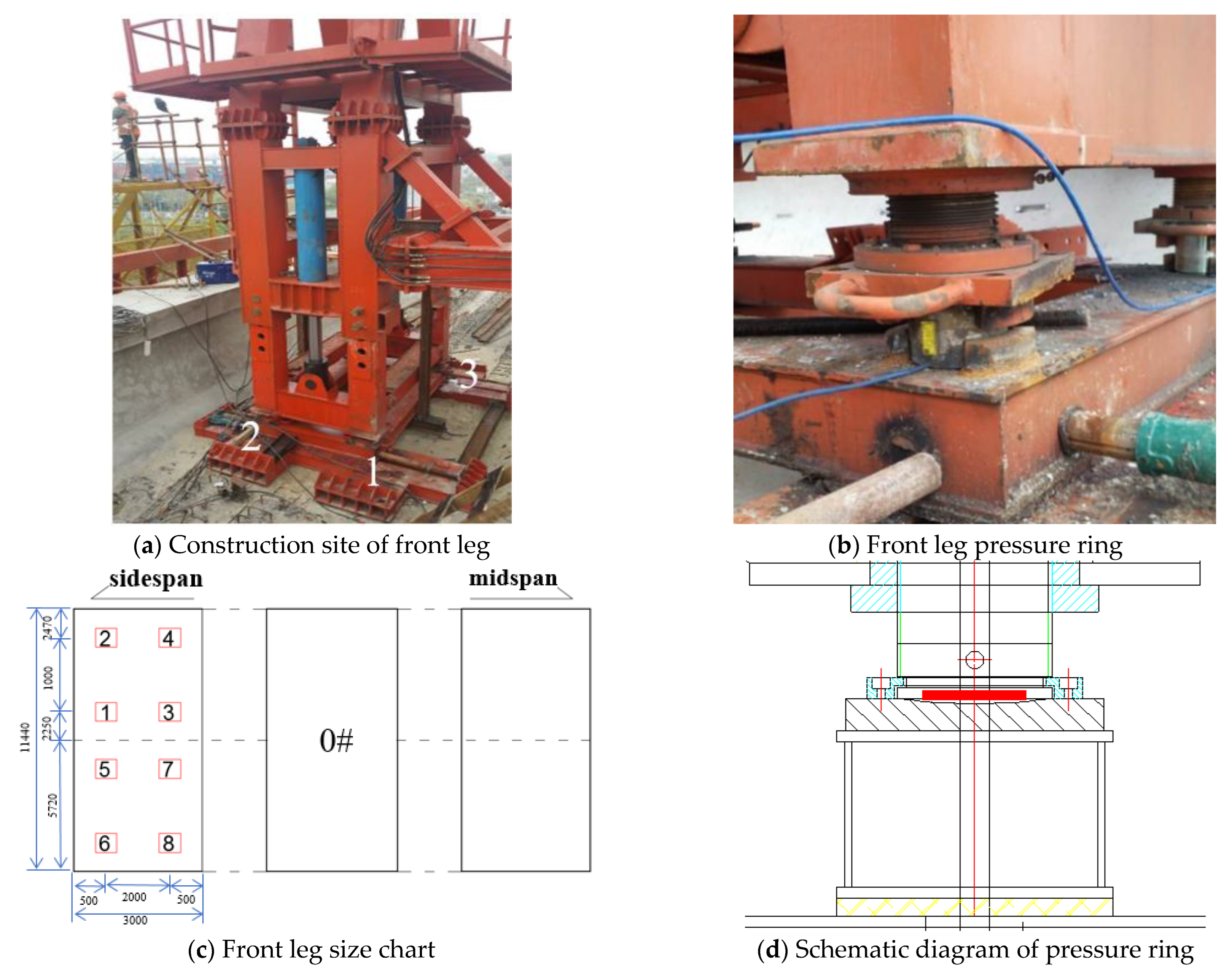
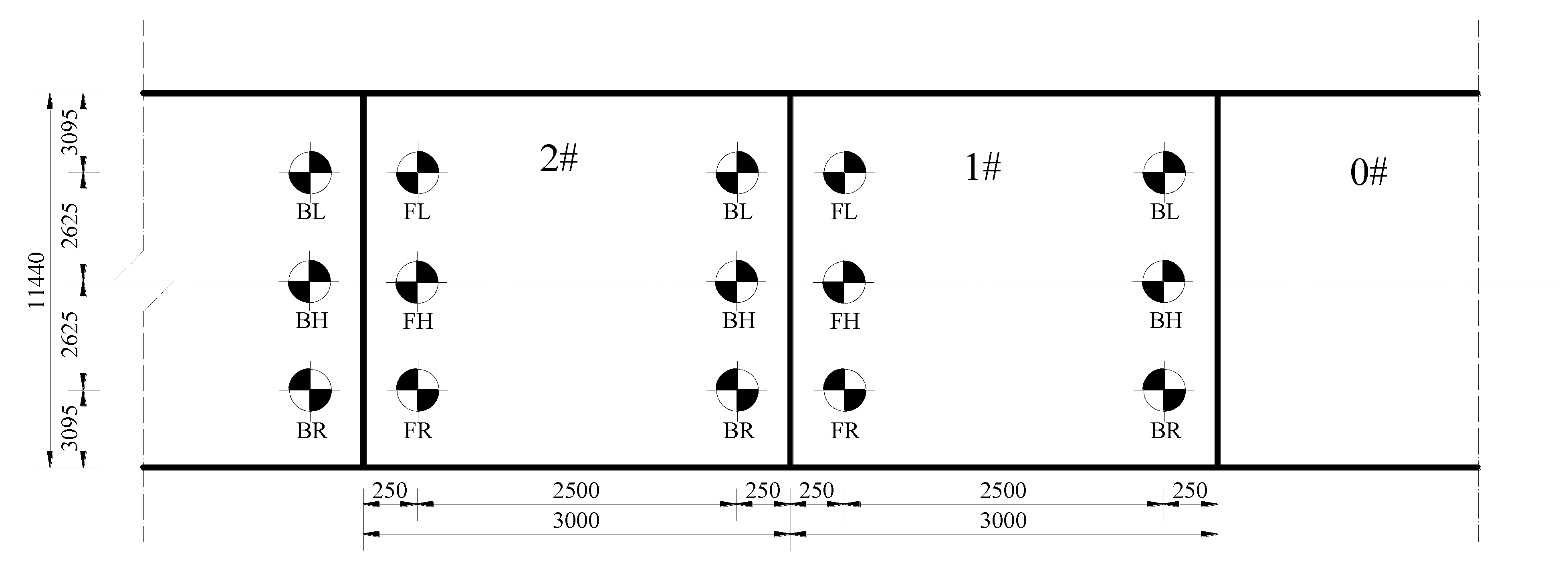
With the continuous assembly of the T-shape structure, the distance between the cantilever tip and the end become longer. The front leg of the bridge erector on the T-shape structure also continues to move away from section 0#, which increases the moment caused by the eccentric load. Consequently, it needs to monitor and control the front leg reaction force of the bridge erector during the hoisting process. Therefore, a pressure ring sensor is set under the front leg of the bridge erection machine. Four pressure ring sensors are set in total as four supporting pads exist in one leg, as shown in
Figure 5. The pressure ring sensor is used to monitor the front leg force of the bridge erector in real time. The reaction force of the front leg can be adjusted in order to reduce the eccentric load on the cantilever T-shape structure. The height of the leg can also be adjusted in order to reduce the reaction force of the front leg. Then, the asymmetric load on the T-shape structure can be controlled.
For example, when lifting segment 1#, the reaction force of the front leg is monitored in actual time. When the front leg reaction force approaches 200 tons, the axial force automatic servo system applies an initial axial force of 250 tons.
3.4. Auxiliary Leg
Considering the impact of the bridge erection machine weight on the load of the T-shape structure, the total length of the bridge erection machine is set to 84 m. Due to the limited total length, it should constantly move forward during the construction process. After assembling the eastern half of the bridge, the bridge erection machine moves to the western half of the bridge by passing the hole.
When the T-shape structure continues to extend, the bridge erector and the legs should continuously move toward the mid-span. When one leg is moving forward, the weight of the bridge erection machine is only supported by the other two legs, which leads to an excessive force on the T-shape structure.
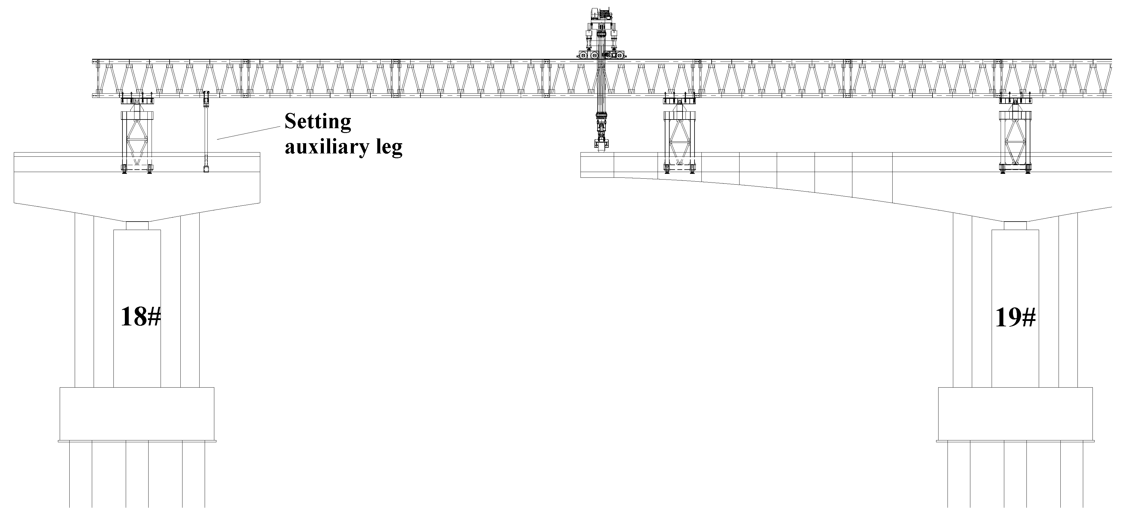
In order to reduce the imbalance moments caused by the leg of the bridge erection machine on the T-shape structure, an auxiliary leg is added in order to replace the leg force that should be moved, as shown in
Figure 6. In the hoisting stage, the force of the moved legs is transferred to the auxiliary leg. In the hole-passing stage, the auxiliary leg is added to assist the bridge erection machine to pass the holes, so that the mechanical state of the T-shape structure is under control.
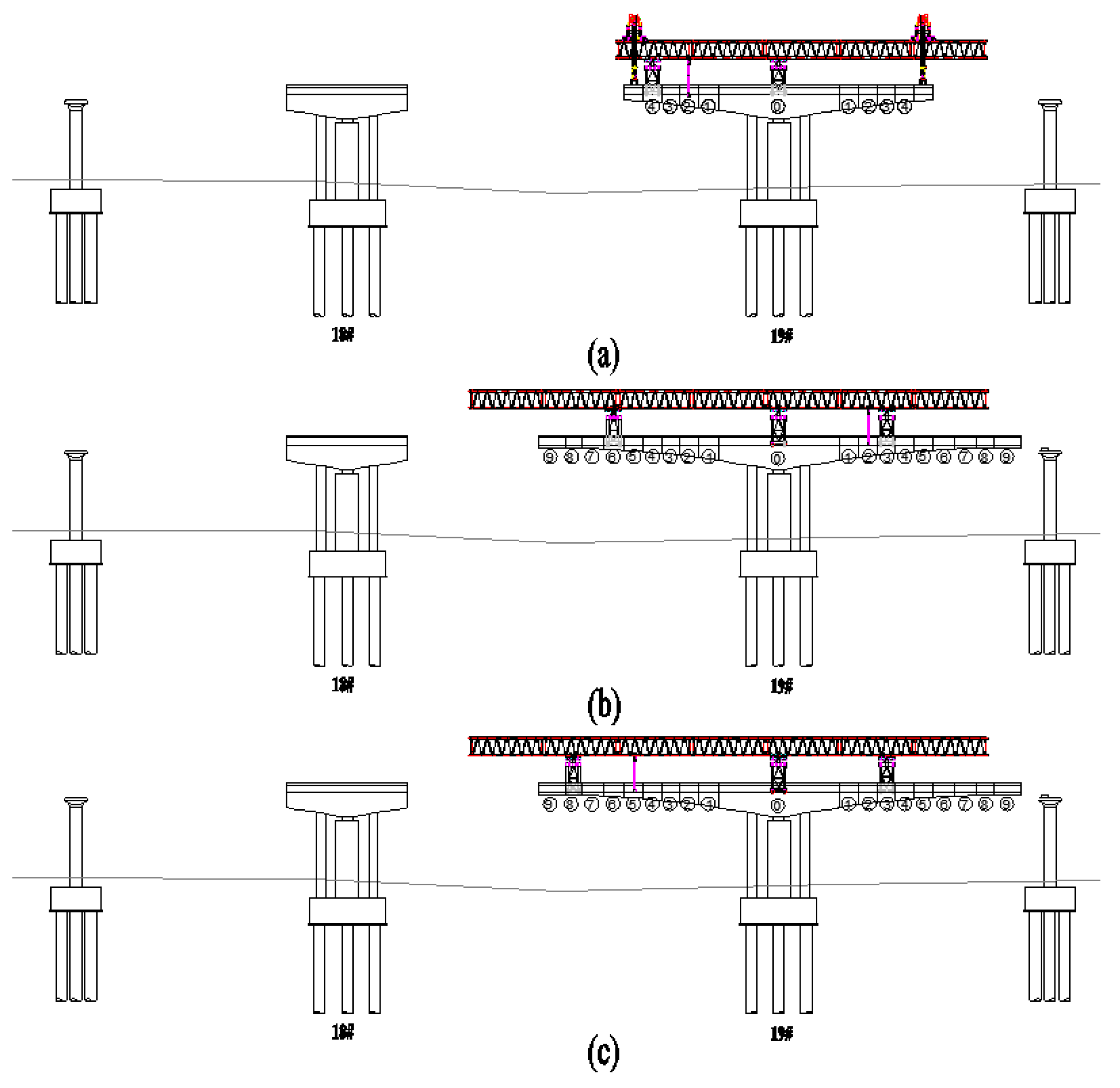
When hoisting section 5#, the main truss of the bridge erection machine should be pushed forward to the beam cantilever, as shown in
Figure 7a. Therefore, the auxiliary leg added before the front leg is retracted and moved to the mid-span. The front leg is then retracted and moved to section 4# of the mid-span. Section 5# is hoisted after the front leg is anchored. The same applies when section 6#, section 7#, and section 8# are hoisted.
During the hole passing, the auxiliary leg is first set on section 2# of the side-span, as shown in
Figure 7b. It can assist the rear leg to move from section 7# to section 3# of the side-span.
The auxiliary leg is installed and anchored on section 5# of the mid-span with the crown block, as shown in
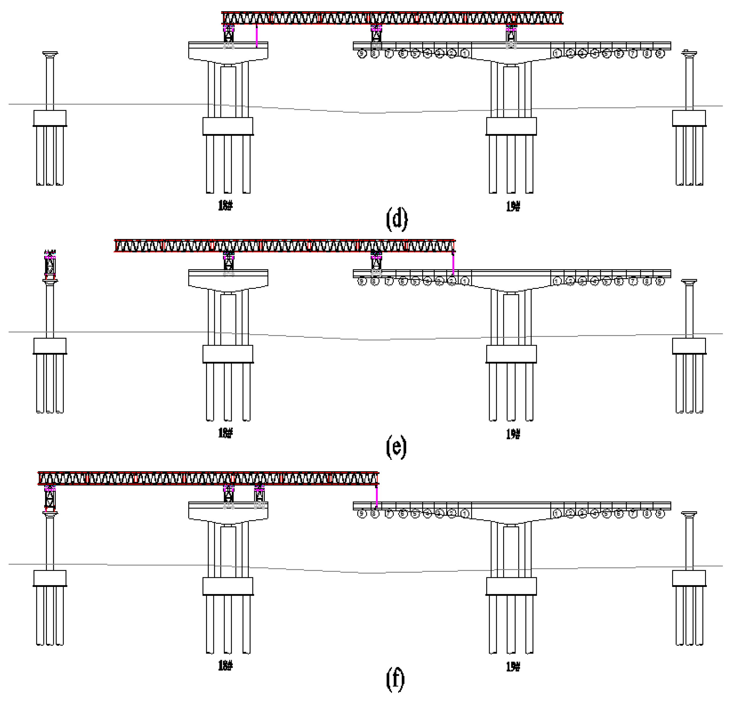
Figure 7c. It can assist the front leg to move from section 7# to section 8# of the mid-span. The auxiliary leg is then installed on section 0# in the western half, as shown in
Figure 7d, and the main truss girder is pushed to it. During this period, when the main truss girder is pushed forward to the front cantilever, the rear leg is retracted and suspended on it. Afterwards, the auxiliary leg is moved and anchored on section 2# of the mid-span and the middle leg is moved and anchored on the western half of the side pier, as shown in
Figure 7e. The main truss is further pushed forward to the tail of the main truss in order to reach the auxiliary leg. In addition, the auxiliary leg is suspended on the main truss girder, which continues to push forward in order to reach section 8# of the mid-span, as shown in
Figure 7f. The auxiliary leg is then anchored. Moreover, the front leg is hung on the main truss girder and moved and anchored on section 0# of the western half of the bridge. Finally, the auxiliary leg is dismantled after the stage is completed.
5. Fem Simulation and Construction Monitoring
The construction process of the bridge is simulated using MIDAS software [
17]. The sensors are placed at measurement points in order to monitor the reaction force of the front leg. The deflection of the beam is measured by the total station during the bridge construction in order to ensure its safety.
5.1. FEM Simulation
The construction stages of the entire bridge are simulated using MIDAS/CIVIL 2019. The impact of the bridge erection machine and the bridge structure is considered in the modeling. A rigid connection is set between the bottom of the bridge erection machine leg and the upper structure of the bridge. The beam and the bridge pier, as well as the main truss and the leg, are rigidly connected. The weight of the Phase II constant load is added to the unit load applied to the bridge.
The bridge model has a total of 1014 nodes and 1695 elements, including 26 nodes and 40 elements of the beam and 524 nodes and 1598 elements of the bridge unit, as shown in
Figure 11. The concrete grade and the steel grade of the beam element are C60 and Q235, respectively. The steel strand is Strand1860.
According to the cantilever assembly construction, the bridge cantilever assembly construction process is divided into the following conditions: hoisting section 1# → hoisting section 2# → hoisting section 3# → ... → hoisting section 9# → hoisting section 10# → passing holes 1~7. In each hoisting stage, according to the calculation, the pre-cast sections are hoisted to the leg of the bridge erection machine as the most unfavorable hoisting point for the analysis.
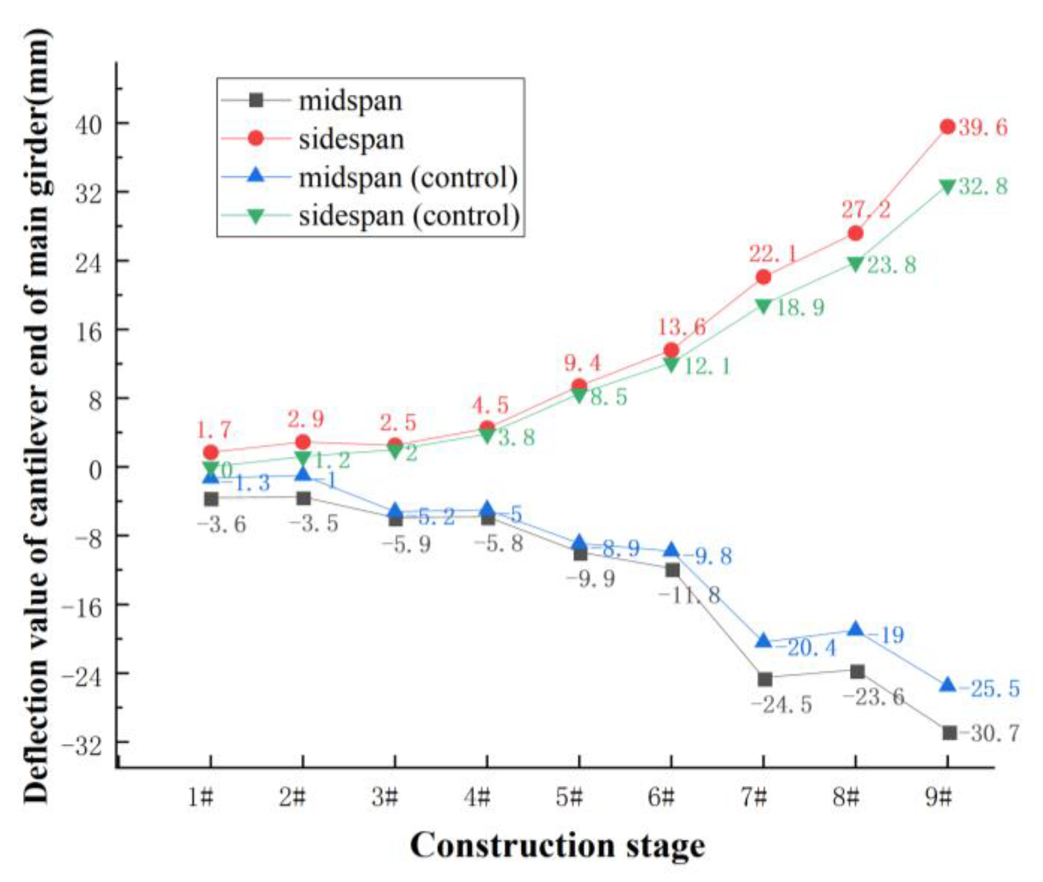
Figure 12 presents the simulated results of the cantilever beam tip deflection in the hoist stage. Due to the eccentric force on the T-structure, the deflection of the side-span beam cantilever is downward while the deflection of the mid-span beam cantilever is upward during the construction stage.
With the progress of the construction stage, the cantilever tip deflection of the side-span beam and the mid-span beam is constantly increased. When section 9# is hoisted, the cantilever tip deflection value of the side-span beam reaches 39.6 mm. After performing the control method of the mechanical state, the cantilever beam tip deflection is reduced to 32.8 mm. Similarly, the deflection value of the cantilever tip of the beam on the mid-span also decreases after being controlled. Therefore, it can be concluded that the previously mentioned mechanical state control methods can efficiently reduce the cantilever beam tip deflection.
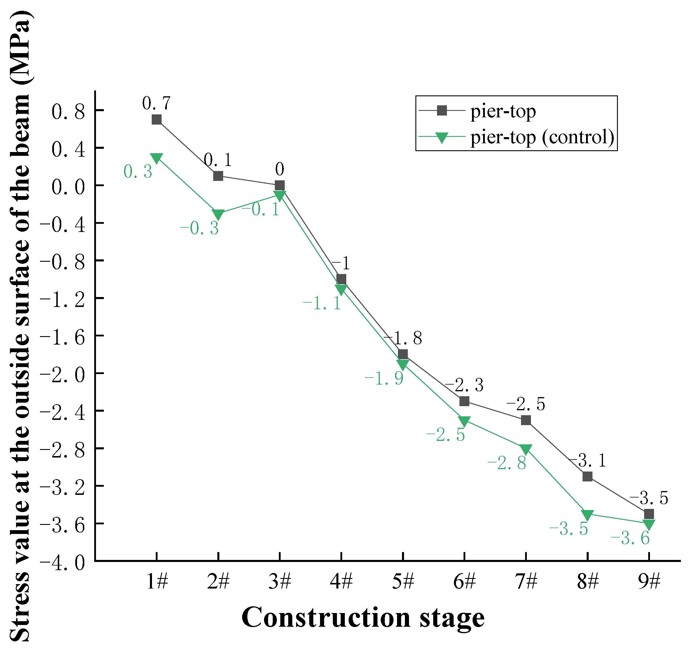
Figure 13 presents the stress value at the outside surface of section 0# during the hoisting stage. When sections 1# and 2# are hoisted, the surface of section 0# shows a tensile stress. An excessive tensile stress will cause a surface concrete cracking of section 0#. After the internal force is adjusted and controlled using the mechanical state control method, the stress at the surface of the beam is reduced. The maximum tensile stress is then 0.7 MPa when section 1# is hoisted. Therefore, this shows that the mechanical state control method can reduce the tensile stress on the surface of section 0# during the construction stage.
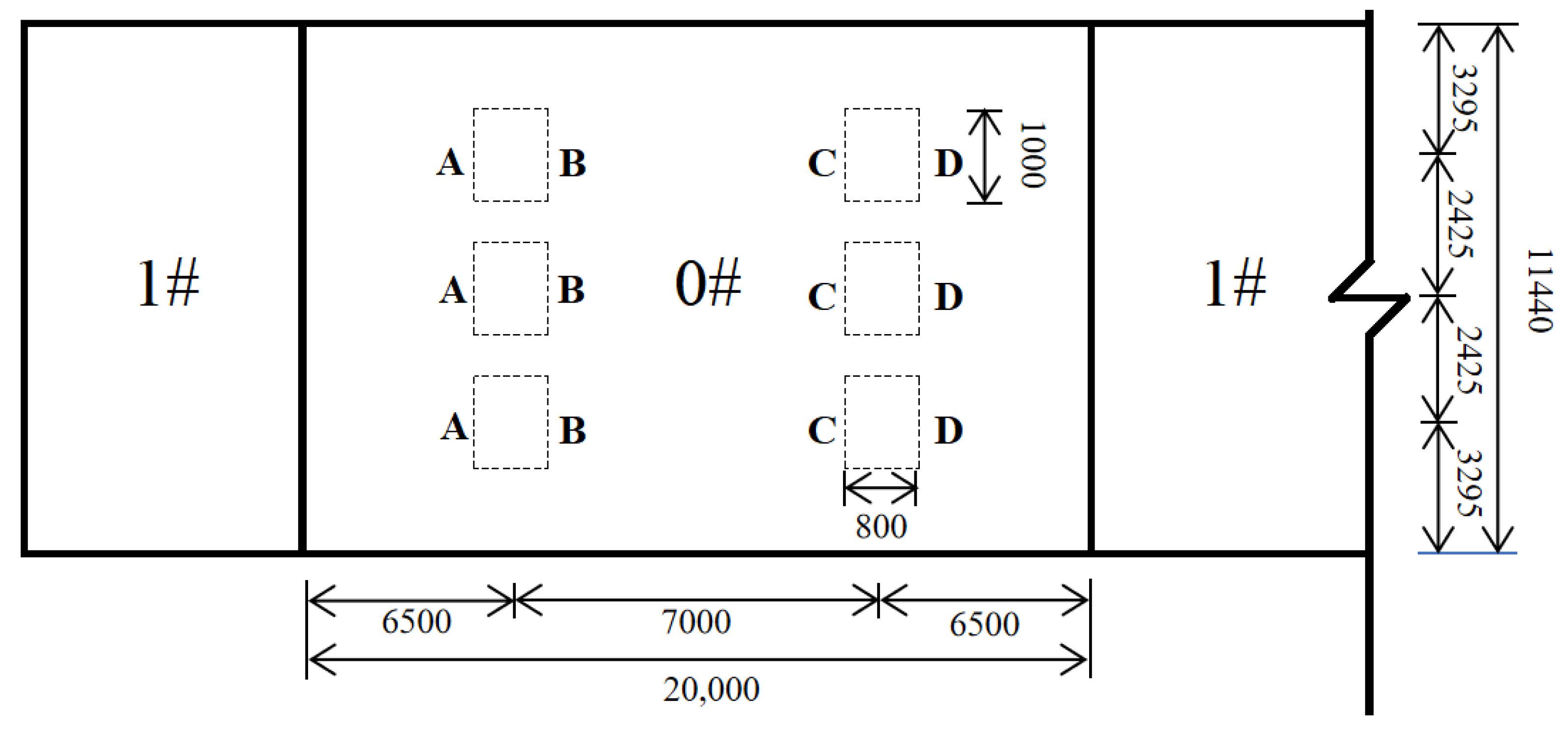
Figure 14 shows the locations of the compressive column.
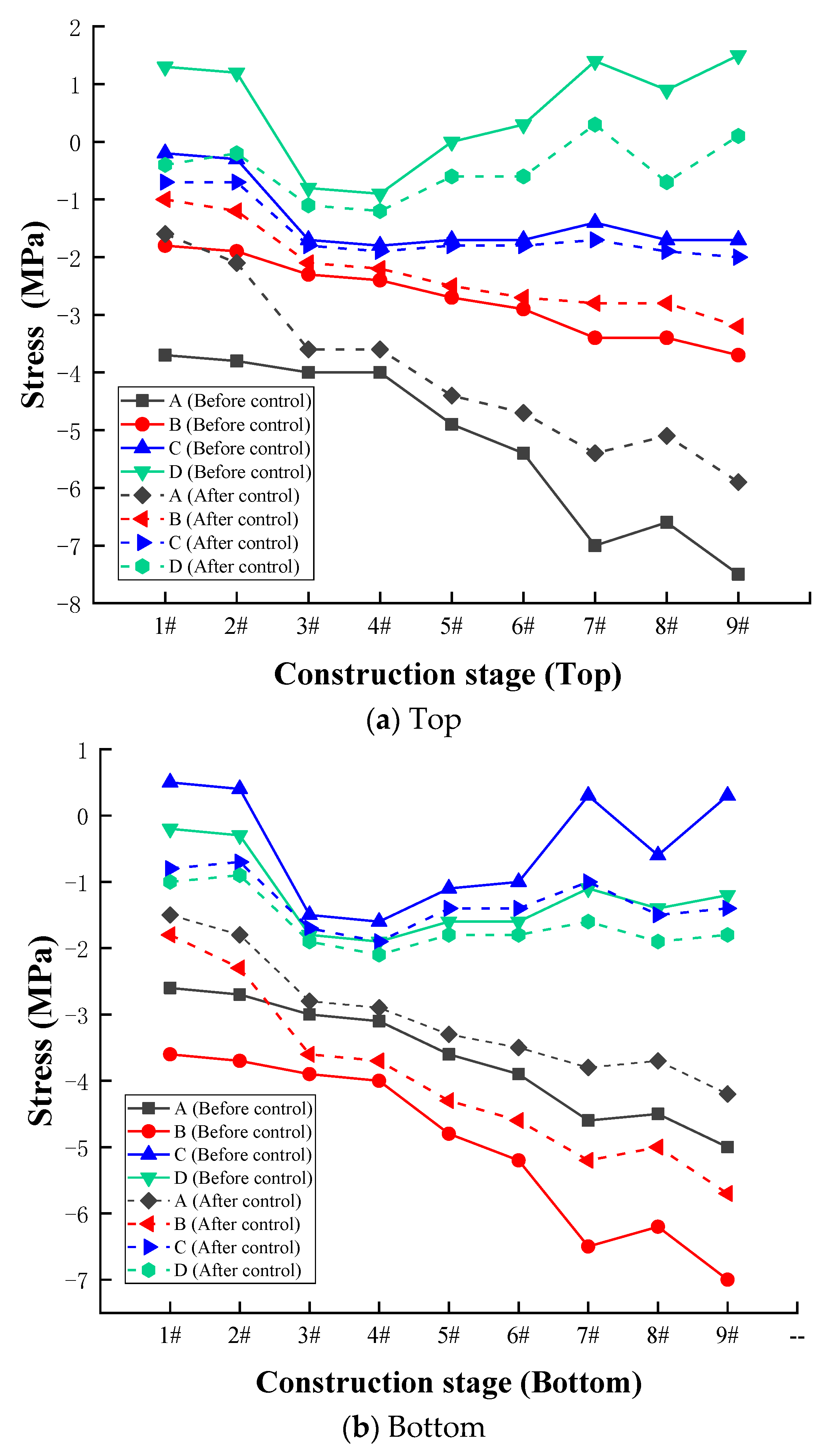
Figure 15 presents the stress value of the compression column. The positive numbers indicate the tensile stress, while the negative numbers denote the compressive stress. The stress on both sides of the compression column is derived by FEM. It can be seen from
Table 1 that the stress is negative on side D, which indicates that side D is the most dangerous place in the construction process. A tensile stress appears when hoisting sections 1#, 2#, 6#, 7#, 8#, and 9#. The tensile stress decreases (or a compressive stress also appears), when the mechanical state control method is used. This demonstrates that the mechanical state control method has well controlled the stress of the compressive column.
5.2. Layout of the Measurement Point
During the construction process, the deflection of the beam and the reaction force of the front legs should be measured. Therefore, measuring points should be placed on them.
5.2.1. Measuring Points of the Front Leg
Before hoisting section 5#, the reaction force of one, three, five, and seven measuring points is tested. In the later stage, due to the gradually increasing length of the cantilever section, it is necessary to increase the measurement points from four to eight when the reaction force of the legs is monitored. Therefore, the reaction force of the front legs is monitored at eight measuring points, as shown in
Figure 5c.
5.2.2. Measuring Points of the Beam
During the construction of the beam, the horizontal coordinates and the elevation of the coordinate control points are monitored by the total station and the level. The total station is set up on the control point in section 0# during the measurement and the rear-view prism is placed on another control point, as shown in
Figure 16.
5.3. Monitoring Results
5.3.1. Reaction Force of the Front Leg
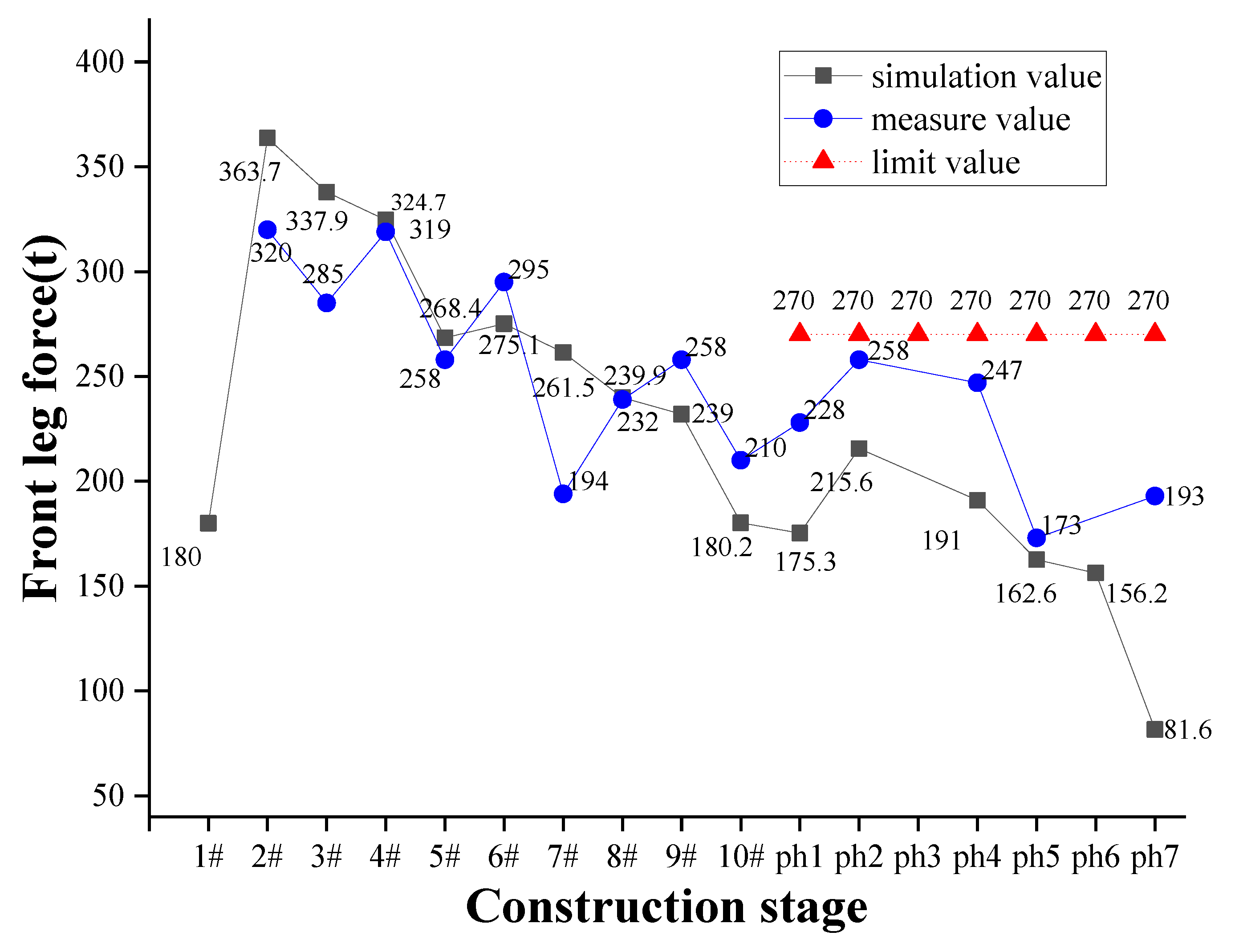
Figure 17 presents the measured value of the reaction force. The reaction force is determined by the pressure ring sensor set at the bottom of the front leg. The FEM results demonstrate that in the hoisting stage of section 2#, the maximum vertical reaction force of the front leg is 363.7 t. As for the construction monitoring results, in the hoisting stage of section 2#, the maximum vertical reaction force of the front leg is 320 tons. In the hole passing stage, the FEM modeling results demonstrate that the maximum vertical reaction force of the front leg is 215.6 tons when passing hole 2. The actual monitoring results of the construction demonstrate that the maximum vertical reaction force of the front leg is 258 tons. Therefore, the actual measurement results are consistent with the simulation results.
In the hoisting phase, the unbalanced bending moment caused by the reaction force of the front leg can be offset using the mechanical state control method. In the hole-passing stage, the warning value of the front leg reaction force is 220 tons, while the limit value is 270 tons. Therefore, the front leg reaction force is within the control range.
5.3.2. Deflection Results of the Beam
During the beam construction, a level is used to monitor the elevation of the coordinate control points. The vertical deformation of the beam is approximately 2 cm. After the bridge construction is completed, the vertical deformation of the beam is in the range of 2~4 cm.
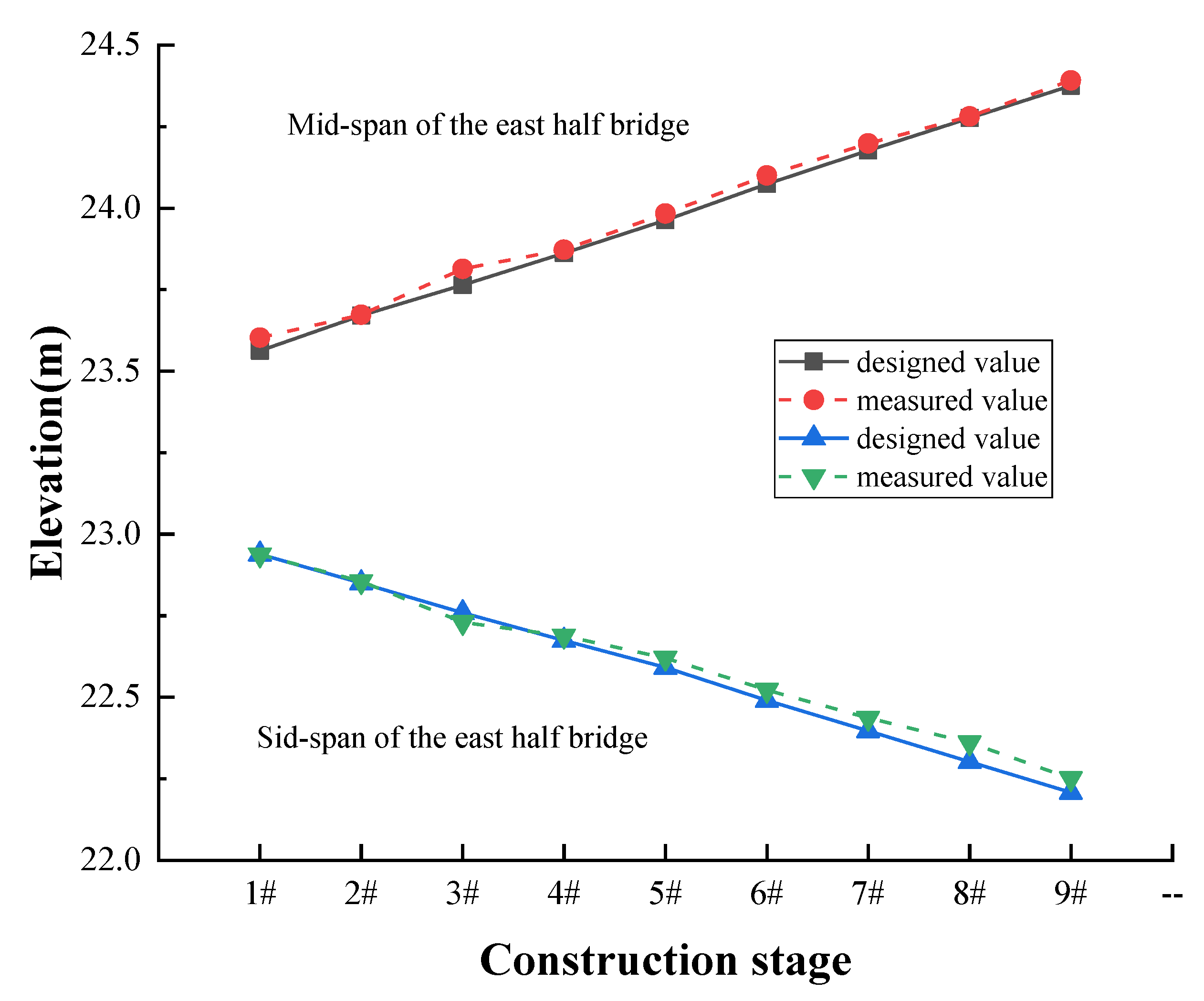
Figure 18 presents a comparison between the measured elevation of the beam and the design calculation elevation. It can be seen that the designed value is almost the same as the measured value. Note that the difference (%) is defined as: (measured value − design value)/measured value × 100%.
Table 1 shows the calculation difference between the designed value and the measured value. When section 8# is hoisted, the maximum difference between the design value and the actual measurement value is 0.262%. Therefore, it can be concluded that a small difference exists, which meets the design and subsequent construction requirements.
In summary, after the four mechanical state control methods are used to control the mechanical state of the bridge during the construction process, the data of the actual construction measurement and FEM meet the construction requirements.
6. Conclusions
This paper presents a novel construction method for an asymmetric cantilever prefabricated and assembled continuous bridge: Shanghai Metro Line 10 over Metro Line 6 with complex construction conditions.
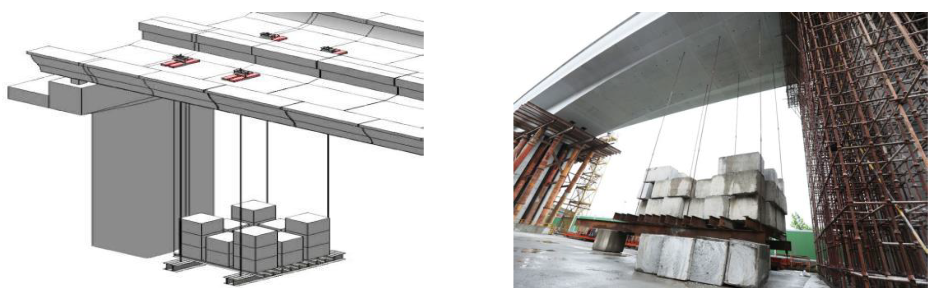
The pre-cast section is first hoisted on the beam using the bridge erecting machine for the entire bridge construction. Because of the unbalanced moment of the T-shape structure caused by the front leg force of the bridge erection machine, four mechanical state control methods and three auxiliary measures are proposed and applied to ensure that the T-shape structure moment remains in a controlled state during the construction process.
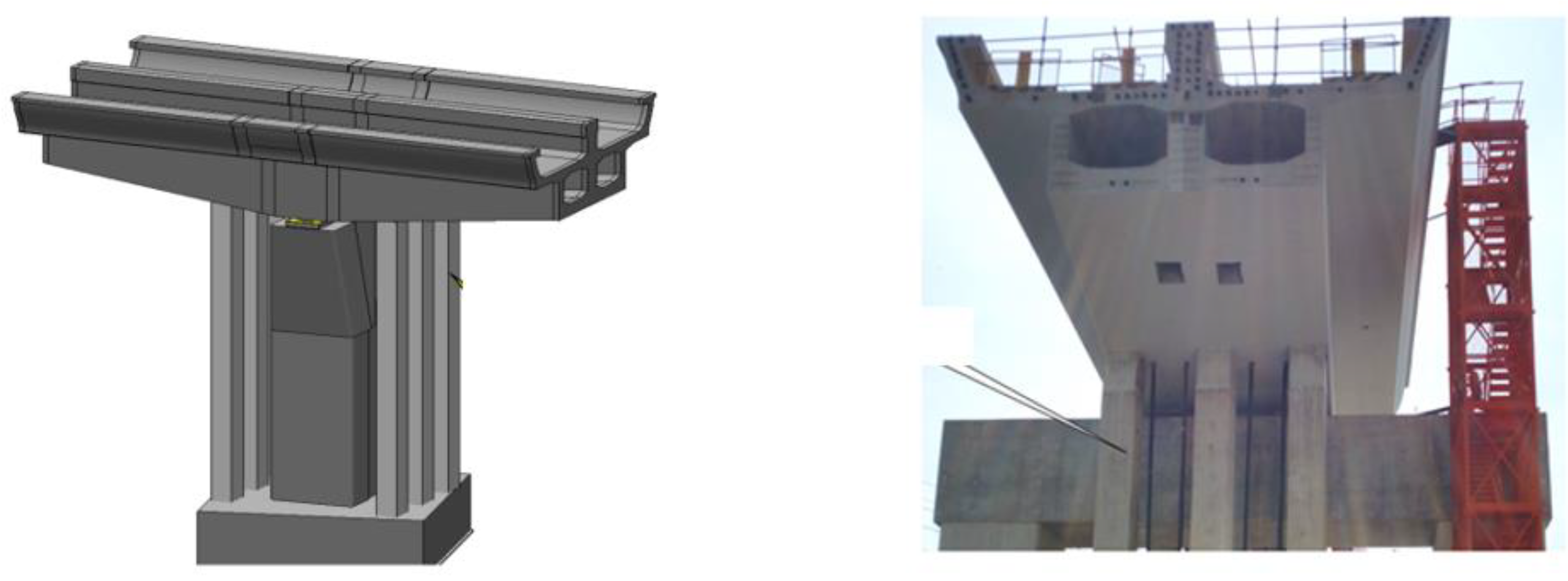
The four mechanical state control methods are tensioning the pre-stressed steel strand, jacking by the axial force servo system, adjusting the leg reaction force, and setting the auxiliary leg. The three auxiliary measures are setting a counterweight at the side-span during the hole-passing stage, setting compression columns at the bridge pier, and setting a temporary pre-stress during the hoisting stage.
The construction process is simulated by FEM and the stress and deflection of the girder are monitored. The simulated and measured stress and deflection of the cantilever T-shape structure are well-controlled and within the limit range during the construction process. The deviation between the measured and simulated stress and the deflection are small and meet the construction requirements.
Finally, this paper provides a valuable experience for the construction of an asymmetric cantilever prefabricated and assembled continuous bridge with limited construction space and a complex environment.

 ,
, 


