Article

Experimental Investigations and Seismic Assessment of a Historical Stone Minaret in Mostar

1
Faculty of Civil Engineering, University “Džemal Bijedić” in Mostar, 88000 Mostar, Bosnia and Herzegovina
2
Freelance Structural Engineer, 88000 Mostar, Bosnia and Herzegovina
3
Expin srl, 35138 Padova, Italy
4
University of Sarajevo-Faculty of Civil Engineering, 71000 Sarajevo, Bosnia and Herzegovina
*
Author to whom correspondence should be addressed.
Buildings 2023, 13(2), 536; https://doi.org/10.3390/buildings13020536
Submission received: 14 December 2022 / Revised: 16 January 2023 / Accepted: 22 January 2023 / Published: 15 February 2023

Abstract

:
Minarets, tall structures, connected or not to the mosque attract attention due to their specific architectural features. Vulnerability to seismic damage has been witnessed throughout history on tall and slender structures after earthquake ground motions. In that respect, it is of the utmost importance to investigate the dynamic characteristics and resilience of historical stone minarets. This paper aims to provide the results of an on-site dynamic investigation of a stone minaret in Mostar and deliver its seismic assessment. The minaret is part of the Tabačica mosque built at the turn of the 16th and 17th century in the City of Mostar, Bosnia and Herzegovina. The on-site investigation comprised dynamic identification of the minaret by ambient vibration testing and qualitative estimation of the masonry wall by sonic pulse velocity testing. Besides the modal analysis a time-history analysis was performed by using the Applied Element Method (AEM), considered an appropriate tool for assessing the behavior of historic masonry structures. A good match is found between the first natural frequency obtained by the on-site investigation and the modal analysis which is a solid basis for further seismic assessment of the minaret as a slender tower-like structure. The concentration of stresses is observed at the transition zones.

1. Introduction

Preserving cultural heritage structures as well as passing knowledge to future generations is of the utmost importance for the history of a certain region regarding the social life of the communities of a given period and the construction technologies utilized at that time. Many of these structures have been exposed to various extreme natural hazards (wind, earthquakes, etc.), inadequate maintenance, and sometimes they have even been neglected. Regardless of all of these negative impacts and influences, they have survived which shows the magnificent engineering work conducted by famous masons centuries ago without the application of any high-level technology [1].
Assessment of cultural heritage buildings has gained a lot of attention in the last decades and numerous researchers have dedicated their investigations in this direction. Analysis of these structures is a rather complex and multidisciplinary task as it requires the involvement of various engineers, architects, conservators, historians, etc. Once collected, the data has to be analyzed by a team of experts from different fields to make a correct decision regarding the potential preservation measures and strengthening techniques. Most of these structures, constructed several centuries ago are made of traditional materials such as stone, brick, and adobe (masonry buildings), and are vulnerable to seismic effects. It is important to state that at the time of construction there were no seismic codes, but structures were constructed based on the knowledge of individual masons. Earthquake destruction triggered the development of seismic codes and their enforcement in different countries. With the development of different software packages, numerical modeling of historic masonry buildings became possible. Each modeling technique has its advantages and disadvantages, as well as field of application. According to D’Altri et al. [2], there are four main classes of numerical strategies for masonry structures. The first class is when the structure is modeled utilizing a block-by-block definition. Masonry is conceived as an assembly of blocks linked together by mortar joints. Page [3] was the first researcher who applied nonlinear analysis to masonry structures. The advantage lies in the ability to model the actual masonry texture and the structural detail; however, in historical structures this is commonly an unknown parameter. This method is typically used for small-scale experimental tests. However, it has been applied for several historical structures [4,5], but this is not common due to its high computational time. This method has been further developed leading to five sub-classes: Interface element-based approaches; Contact-based approaches; Textured continuum-based approaches; Block-based limit analysis approaches; and Extended finite element (FE) approaches. For more details, please see D’Altri et al. [2]. The second class represents the continuum models with the application of adequate homogeneous constitutive laws. As the mesh is not connected to the size of masonry elements the computational time is greatly reduced. Description of the masonry’s constitutive laws could be undertaken by direct approaches or homogenization procedures and multiscale approaches. The direct approach was used for modeling the historical church by Pantò et al. [6] and complex masonry structures by Abbati et al. [7]. The smeared crack, damage, and plastic-damage models found a massive application in the assessment of masonry structures due to their implementation in various software, and the fact that only a few mechanical characteristics of masonry are needed as input, significantly reducing computational time. In this way anisotropy of masonry is neglected but masonry is modeled as an isotropic material. Several researchers applied this modeling procedure to model historic towers [8,9,10,11,12]. Homogenization procedures and multiscale approaches are mainly used for small-scale elements. The shortcoming of models based on the finite element method is that it is not possible to simulate the mechanical interaction between multiple bodies, which is important in the analysis of structures exposed to impact loads as well as in the analysis of the progressive collapse of structures. With macroelement models, the structure is composed of piers and spandrels, and rigid elements. There are generally two approaches—equivalent beam-based and spring-based approaches. Finally, in the geometry-based models, the masonry structure is determined as a rigid body. Additionally, a discrete element method (DEM) as a micro modeling approach is able to provide adequate masonry representation on the level of masonry elements and joints. In that respect, only limited research is available on the application of this methodology for masonry structures, such as the work done by de Felice [13], Pulatsu et al. [14], and Lemos [15]. The mechanical behavior of block-based masonry walls is well represented by DEM as presented in [16,17,18]. The application of DEM was used as well by [19] for modeling the infilled masonry frames. Dimitri and Zavarise [20] explored the application of DEM in Gothic buttresses of trapezoidal and stepped shapes. It has been concluded that this procedure is useful in the prediction process of the first-order seismic behavior of unreinforced masonry (URM) structures in terms of collapse load and collapse mechanism. The model was able to predict in an accurate manner the dynamic response of the structure. Alexakis and Makris [21] elaborated on the application to masonry arches. An interesting work was presented by [22] for an aqueduct in Portugal and a multi-leaves arch-tympana of a church in Italy. Models based on the DEM were developed for the analysis of problems in which there is a mechanical interaction between multiple bodies that can have large displacements and rotations. The main characteristic of the DEM is the modeling of the structure as a set of discrete elements interconnected by contact elements, which enabled its application in the analysis of structures with complex heterogeneous compositions (masonry structures). This approach makes it possible to simulate the collapse of the structure due to rotation, sliding, and impact loading. A major disadvantage of this method is its inability to describe the state of stress and deformation within discrete elements, which is especially important when analyzing the appearance, development and propagation of cracks.
A new modeling philosophy has emerged which combines both the finite element method (FEM) and the discrete element method (DEM), and is known as the applied element method (AEM). It was originally developed for the simulation of structural demolition of reinforced concrete buildings in a controlled manner [23,24,25]. This new method uses the advantages of both approaches, meaning the accuracy of the FEM until elements separate and DEM when the elements become detached. The advantage of this method is that it is able to automatically simulate the separation of the elements and follow up all stages until the collapse of the structure and can predict the falling debris. With more than two decades of continuous research and development, AEM has been proven to be the only method that can track structural collapse behavior passing through all stages of loading; elastic, crack initiation and propagation in tension-weak materials, element separation, element collision (contact), etc. The advantage is seen in its implicit time-integration frameworks as opposed to DEM which uses explicit solvers and direct integration. Malomo et al. [26] utilized AEM for the assessment of a full-scale URM prototype representative of a typical Dutch detached house which was experimentally investigated on a shaking table. A good relation was obtained between the experimental data and the numerical model. The general positive impression of the behavior of the numerical model was additionally supported by the damage evolution. The model was capable of capturing the fractures’ propagation. The global behavior of the structure was correctly captured in the model. Hadhoud et al. [27] modeled a Margherita Palace with the application of the AEM modeling procedure. The heritage masonry Margherita Palace was built two centuries ago and was heavily damaged by the strong 2009 L’Aquila earthquake. The model was able to capture the damage to the structure caused by the earthquake and the damage pattern was very similar to the one observed on the structure after the earthquake. The weakest point of the structure was detected leading to the need for remedial and strengthening measures. Diana et al. [28] used the AEM model to validate the results obtained from the simplified approach of the LV1-church form (the mechanism related to the belfry) and by a kinematic approach. It was noted that the non-linear verification was reasonable and true with the damage pattern obtained by the AEM model and then by the simplified procedures. Evidently, the AEM is capable of simulating both the in-plane and out-of-plane failure modes in masonry structures and their individual components exposed to either static or dynamic actions [29]. As many buildings throughout the world are constructed as masonry-infilled reinforced concrete structures, their seismic performance with the application of the AEM models was explored [30]. A structure with eight storeys was exposed to time history analysis taking into account four different configurations: one including a soft storey, then this soft storey was retrofitted, an RC bare frame, and RC with masonry infill in all floors. The AEM modeling was used as well to evaluate strengthening measures for a URM building [31].
After the 2011 Van earthquake, an extensive campaign was conducted in order to determine the dynamic characteristics of eleven minarets in Turkey [32]. Three techniques and three excitation levels were used for the determination of the dynamic characteristics. Seven frequencies were determined with the application of FDD, EFDD, and SSI techniques. In this specific case, seven minarets were modeled using a FEM without the mosque. Research on minarets, but this time those beside historic, contemporary, and combined minarets was conducted by Çaktı et al. [33]. Additionally, the Mihrimah minaret was modeled utilizing a discrete element method and ten various time history accelerations were used for non-linear dynamic analysis [33]. The Grand Mosque in Bursa was modeled with the application of FEM and seismic performance analyses were conducted on four different models. Model 1 took into account most details while the most simplified model was the fourth one. It has been noted that the stairs have to be taken into account as their influence cannot be neglected in the numerical analysis, although other elements could be neglected [34]. How geometrical characteristics affect the dynamic behavior of the minarets was investigated by Livaoğlu et al. [35]. The dynamic characteristics were determined by the ambient vibration tests and with the application of Enhanced Frequency Domain Decomposition (EFDD) and then this data was used for validation of the numerical model. In total, seven minarets in Bursa were investigated. A simple equation was proposed for the determination of the natural period which is a function of the cross-sectional area, outer diameter, inner diameter, height, and material density of the minaret as a result of OMA investigations and numerical models. However, additional investigations have to be done in order to take into account the stiffness of the boot, the ratio between different segments of the minaret, and the boundary conditions, as their influence cannot be neglected and have to be taken into account in the calculations [35].
Döven et al. [36] investigated the Yeşil Mosque (Green Mosque) in Kütahya and the changes in the dynamic behavior of the structure in case the balcony of the minaret is open or covered. A comprehensive study of the Mustafa Pasha Mosque located in the central part of the city of Skopje (Macedonia) was performed in 2011 by Portioli et al. [37]. The model of the mosque was scaled to 1:6 with respect to the length and a shaking table test was performed. A numerical model of the mosque was created. The structure was exposed to various seismic loads and the results of the numerical models were calibrated and validated with the results obtained on the shaking table test. Details of the experimental investigation can be found in Krstevska et al. [38] and Tashkov et al. [39]. Additionally, a strengthening procedure was proposed to avoid the propagation of cracks in the directions of the maximum principal stresses, out-of-plane failure, and other types of damage that were observed as results of the numerical modeling; for details, please see Krstevska et al. [38]. A vulnerability assessment of the Al-Askari Shrine exposed to gravity loading as well as seismic loads with the application of the finite element method was conducted by Yekrangnia and Mobarake [40]. The investigation of the gravity loads was needed to check the capacity of the supporting piers to take over the load of the newly constructed dome, as the original dome was destroyed by blast loading. In view of possible earthquake damage to the Al-Askari Shrine, it was required to conduct this analysis as well. Due to the complex geometry and material characteristics, macromodeling was carefully chosen as the modeling method. The whole mosque and the minaret were elaborated and again one of the most critical parts to be identified was the lower part of the minaret; thus, cracks might propagate through the base of the minaret. Calculations due to seismic actions revealed the vulnerability of the structure in the form of crack widening in the piers, leading to asymmetrical movement and finally to the formation of diagonally rising cracks in the dome. Additionally, it was the new minarets that were identified as the most vulnerable elements requiring strengthening (Yekrangnia and Mobarake [40]).
The most remarkable and glorious historic fired brick 12th-century Islamic structure, Gonbad-e Qābus in Iran, was assessed by Ebrahimiyan et al. [41]. There was very little data regarding the material properties; only the average compressive strengths of three masonry bricks were available. Behavior in compression and tension was chosen to be represented by the Concrete-damaged plasticity model. As in the case of Al-Askari Shrine, macromodeling was selected as an adequate modeling procedure. In this specific case, the equivalent static force method was used for obtaining the nonlinear behavior of the structure exposed to gravity and seismic loads. The results of the calculation showed that the collapse-prevention level is satisfied meaning that there is no fear of collapse and structure overturning. Nevertheless, it was noted that adequate measures should be considered regarding the strengthening of the structure (Ebrahimiyan et al. [41]). Five timber minarets in the city of Sakarya (Turkey), located in one of the most seismically prone zones (North Anatolian Fault Zone) were researched by Bağbancı et al. [42]. The two most devasting earthquakes which caused significant damage to the structures or even collapse were the 1999 Düzce (Ms = 7) and Kocaeli earthquakes (Ms = 7.8), the 1967 Sakarya-Akyazı earthquake (Ms = 7.8), and the 1943 Sakarya-Hendek earthquake (Ms = 6.6) [43]. As a result of experimental tests and measurements conducted on the site, Bağbancı et al. [42] proposed a new equation for obtaining the natural frequency; besides being a function of height, cross-sectional area, and material, this became a function of construction techniques of the outer walls of the minarets. The application of this proposed new equation led to an error of less than 10% which may be considered acceptable.
Işık et al. [44] determined the material characteristics of the local Bitlis stone that was used for the construction of the Five minarets (Ulu Mosque Minaret, Şerefiye Mosque Minaret, Meydan Mosque Minaret, Kalealtı Mosque Minaret, and Gökmeydan Mosque Minaret); these represent one of the most famous treasures of Bitlis (Turkey), referenced in the famous folk lyrics “Five Minarets in Bitlis”. Once the material parameters were determined, modal analysis and the minarets’ seismic performance were obtained with the application of the Turkish Building Earthquake Code. Further work and investigation of the Ulu Mosque’s minaret in Bitlis (Turkey) was performed by Işık et al. [45]. The assessment of the minaret was conducted by applying the current and previous seismic code in Turkey, enabling the comparisons of the minaret’s behavior. As well, the calculation was performed for five different geographical locations in the same earthquake hazard zone and four different earthquake ground motion levels (DD-1, DD-2, DD-3, and DD-4), with the probability of exceedance in 50 years. As in previous cases, the macromodelling technique was selected.
A comprehensive investigation and seismic assessment of a reconstructed mosque, which was originally built in the early 1800s within the Bigali castle was done by Gunes et al. [46]. After the on-site (visual inspection) and laboratory tests (mechanical, chemical, and mineralogical analyses) to obtain as much as possible information regarding the structure and its ruins, it was necessary to propose a reconstruction procedure and perform adequate numerical analysis. Due to the specific features of this case study and its importance three different levels of structural analysis were conducted (linear, kinematic, and pushover analysis). In this case also, the minaret was modeled separately from the mosque. The proposed methodology can be applied to the evaluation of similar cultural heritage buildings. Devastation and damage to the minarets after the earthquake which hit the Sivrice district of Elazig city on 24 January 2020 was investigated by Yetkin et al. [47]. The sections where the damage occurred in the minarets were determined, and the reasons for this damage were evaluated. Commonly, the soil effects in the calculations are neglected, leading to potentially incorrect results in soft and loose soils, although this approach may provide adequate results in stiff soil types [48]. Haciefendioğlu et al. [49] concluded that the soil-structure interaction affects the dynamic characteristic of the scaled reinforced concrete minaret. As the soil type changed from sand to clay-gravel the frequency of the minaret increased. Altiok and Demir [50] investigated the effect of the soil structure interaction on the seismic behavior of the Lala Mehmet Pasha minaret, located in Manisa (Turkey). They used the OMA method to calibrate the model, leading to a significant reduction of the initial Young’s modulus, and the difference in the first mode frequency of only 0.03%. Linear type history (LTH) and nonlinear type history (NLTH) analyses were conducted to obtain a reliable formulation of the damage pattern on the structure exposed to significant earthquake motion. The sixth-largest mosque in the world, Faisal Mosque, located in Islamabad (Pakistan) was studied by Akhlaq et al. [51]. The four minarets are completely separated from the mosque. The total length of the reinforced concrete minaret is 90 m. Application of the OMA was utilized and the three identification techniques were used to determine the modal properties. This data was used for calibration of the FEM model by manually correcting the updating of the modulus of elasticity and correcting the weight of the nonstructural elements. Işık et al. [52] proposed a new empirical formula for determination of the minaret’s periods as a function of heights. Additionally, estimation of the ten natural periods as a function of various materials (thirteen taken into account) were estimated with the application of the Artificial Neural Network (ANN) model. There was excellent agreement between the values obtained by experiment and the values estimated by ANN (less parameters were used).
There are several aims of the paper. For the first, the time horizontal to vertical spectral ratio (HVSR) method was utilized to determine the dynamic characteristics of the minaret. These results were compared with the frequently used operational modal analysis (OMA) and a certain consistency was noted. Additionally, the quality of the three-leaf stone masonry used for the mosque building and the minaret base was determined using the sonic velocity test revealing its solid quality. The goal was to determine the seismic behavior and performance of one of the significant minarets in Bosnia and Herzegovina. For this aim, for the first time, the applied element method was used for the nonlinear seismic assessment of the minaret located in Mostar, Bosnia and Herzegovina.
The paper is organized into several sections. Section 2 is devoted to the historical background of the Tabačica mosque as one of the significant and unique monuments of Islamic sacred architecture in Mostar. Geometrical and architectural features are presented in detail together with experimental results for the “tenelija” stone. Section 3 is dedicated to the new experimental study that was conducted in 2022. Utilizing non-destructive techniques, the experimental work aimed to determine the natural frequencies and damping ratios. This was done with the application of two methods, the horizontal-to-vertical spectral ratio (HVSR) method and the operational modal analysis method (OMA). The obtained parameters are used later for the calibration of the numerical model. Secondly, to determine the quality of the masonry, the sonic velocity test (SPVT) was performed. Section 4 is devoted to the modeling of the minaret. For the first time, a nonlinear model that is based on AEM, a derivative of the FEM and DEM, is utilized. The connection between the elements in the AEM is provided by springs, meaning that the plastic hinges come as a result of the analysis and not as input as in FEM. The first modal analysis was conducted and a comparison was made with the experimental results. As previously mentioned, this was used for the validation of the model. Nonlinear time history analysis of the minaret exposed to artificial earthquakes is described in the second part of Section 4. Maximum lateral displacement in X and Y directions, maximum and minimum principal stress contours under the earthquake ground motion for the three sets are presented. The article concludes that there is a good consistency between the experimentally obtained frequency and the numerical model. The sonic velocity test revealed that the masonry is of solid quality. Once again, the transitional regions were identified as the most vulnerable points once the minaret is exposed to seismic loading.

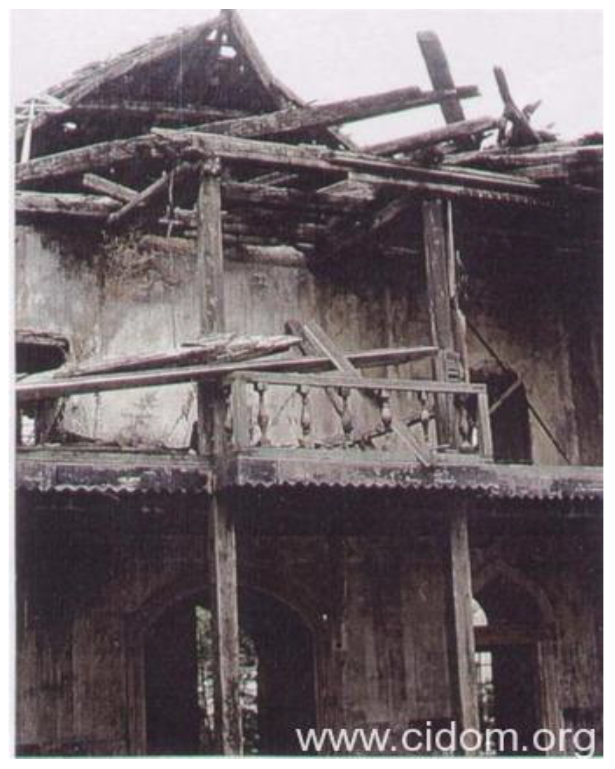
2. Historical Background of Tabačica Mosque

Traditional minarets in Bosnia and Herzegovina dating from the period of Ottoman rule from the 15th to 19th century can be categorized into three groups or types. Type I are stone masonry minarets of predominantly polygonal outer shape; type II are stone masonry minarets of predominantly squared outer shape and type III are timber structured minarets of polygonal outer shape [53]. The most representative and common type is the type I which is the subject of the research presented in this paper. Minarets of this type in Bosnia and Herzegovina are usually constructed with one balcony, as for the minaret in Tabačica mosque (Figure 1a). The cross-section of this minaret is presented in Figure 1b. Similar-looking minarets with more than one balcony also made of stone masonry may be found in other historic areas of the Ottoman empire [54].
As far as it is known, 36 mosques and masjids were built in Mostar, and they typically bear the names of their founders, except Tabačnica. It was built on the river Radobolja, vaulted with two stone vaults, which is why it is known as “the mosque where the imam is on dry land and the congregation is on water”. This mosque was built at the turn of the 16th and 17th centuries at the request of Hadži-Kurt, representative of one of the oldest families in Mostar. It is located on the right bank of the Neretva, about a hundred meters from the Old Bridge, next to “Tabhana”, a neighborhood where leather was tanned, processed, and sold.
The Tabačica mosque is one of the most important monuments of Islamic sacred architecture in Mostar. Its architecture differs in some details from the architecture of other Mostar mosques. The architectural specificity was mostly influenced by the place and environment in which it was built (Figure 1a). It is located directly in front of the “Tabhana”, a leather processing complex, and was mostly visited by members belonging to that society. In Bosnia and Herzegovina, leather tanners built mosques in front of “tabhanas” in five cities (Sarajevo, Mostar, Banja Luka, Visoko, and Tešanj). The name Tabačica was derived from “Tabhana”, and became so familiar to the people of Mostar that over time the name of its founder was completely forgotten. It is said that eighty leather tanners used to worship in it, which would speak of the number of the leather guild in Mostar. Towards the end of Ottoman rule, the Tabačica mosque was repaired and painted inside by Hadji Arif Effendi Kajtaz with his resources. The next conservation and restoration works were carried out in 1954. During the aggression against Bosnia and Herzegovina, the Tabačica mosque suffered massive damage (Figure 2 and Figure 3). The minaret was completely destroyed. The Tabačica Mosque was reconstructed and re-equipped for prayer in 2000 [55].
The minaret was reconstructed using the “Tenelija” stone extracted from the nearby quarry. The present condition of the reconstructed minaret after 2000 is shown in Figure 1a.

2.1. Climate and Seismicity Investigation

In the period from 1858 to 2018, the average annual temperature in Mostar was 16 °C. The warmest month of the year is July, with an average temperature of 26 °C, and the coldest is January, with an average temperature of 5 °C. The highest precipitation is in November and the lowest precipitation is in July, with a difference of 47 mm. The month with the highest relative humidity is February (85%) and the lowest relative humidity is August (62%). Mostar typically receives about 93.95 cm of precipitation and annually has 141.13 rainy days. The average hourly wind speed in Mostar experiences significant seasonal variation during the year. The direction of the wind varies over the year. The wind blows for the majority of the year from the east, for two months from the south, and less than two months from the north. In the period from 1990 to 2022, several earthquakes occurred near Mostar. During past years in Mostar, moderate earthquakes with magnitude 5.0–5.9 on the Richter scale were observed. Several earthquakes had a magnitude in the range of 4.0–4.9 on the Richter scale. The city of Mostar is located in a seismically active zone with a peak ground acceleration (PGA) equal to 0.26 g for the return period of 475 years [58], and according to the calculations conducted by Ademović et al. [59], vulnerability of the buildings in Mostar is very high.
During the visual inspection of the minaret, damage due to ascending and descending moisture has been noted as illustrated in Figure 4a,b respectively. Several dead pigeons were noted in the staircase of the minaret as once they entered the staircase, they were not able to exit. The birds did not cause any damage to the structure and no threats by insects were noted.
There are no signs of damage on the minaret itself after the reconstruction except for a minor biological attack at the bottom of the base (Figure 5). However, plaster spalling on the side of the mosque building is visible along the vertical joint between the minaret and the mosque building (Figure 6), which was not present shortly after the reconstruction (Figure 7). The metal grounding rod runs vertically along the joint, which might have been generating this damage over a period of 20 years.
There are smaller damage impacts visible on the mosque building due to moisture (Figure 4a) and biological attack (Figure 4b). There is damage to the stone roof slabs at the eaves (Figure 8), and a vertical crack can be seen on the western façade of the attached shop building (Figure 9).

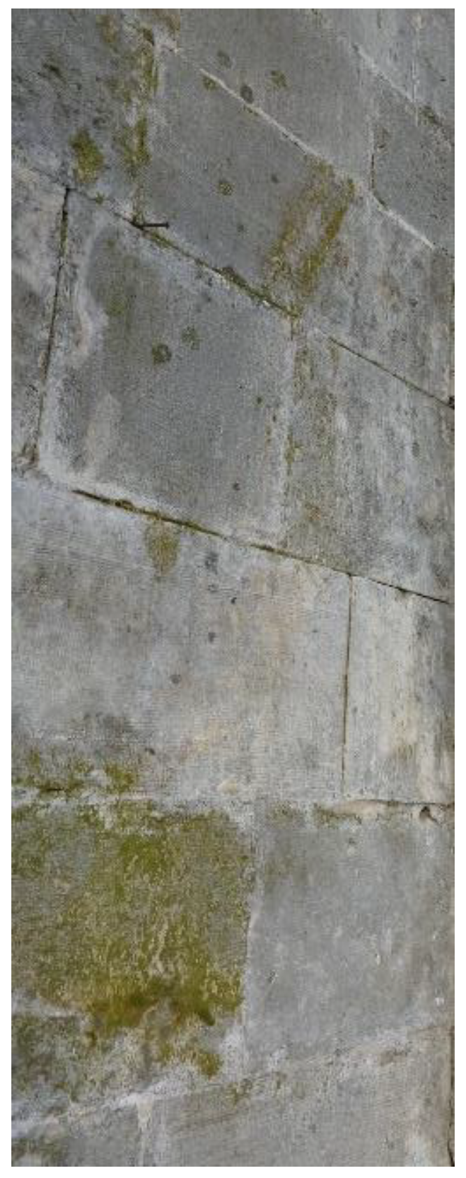
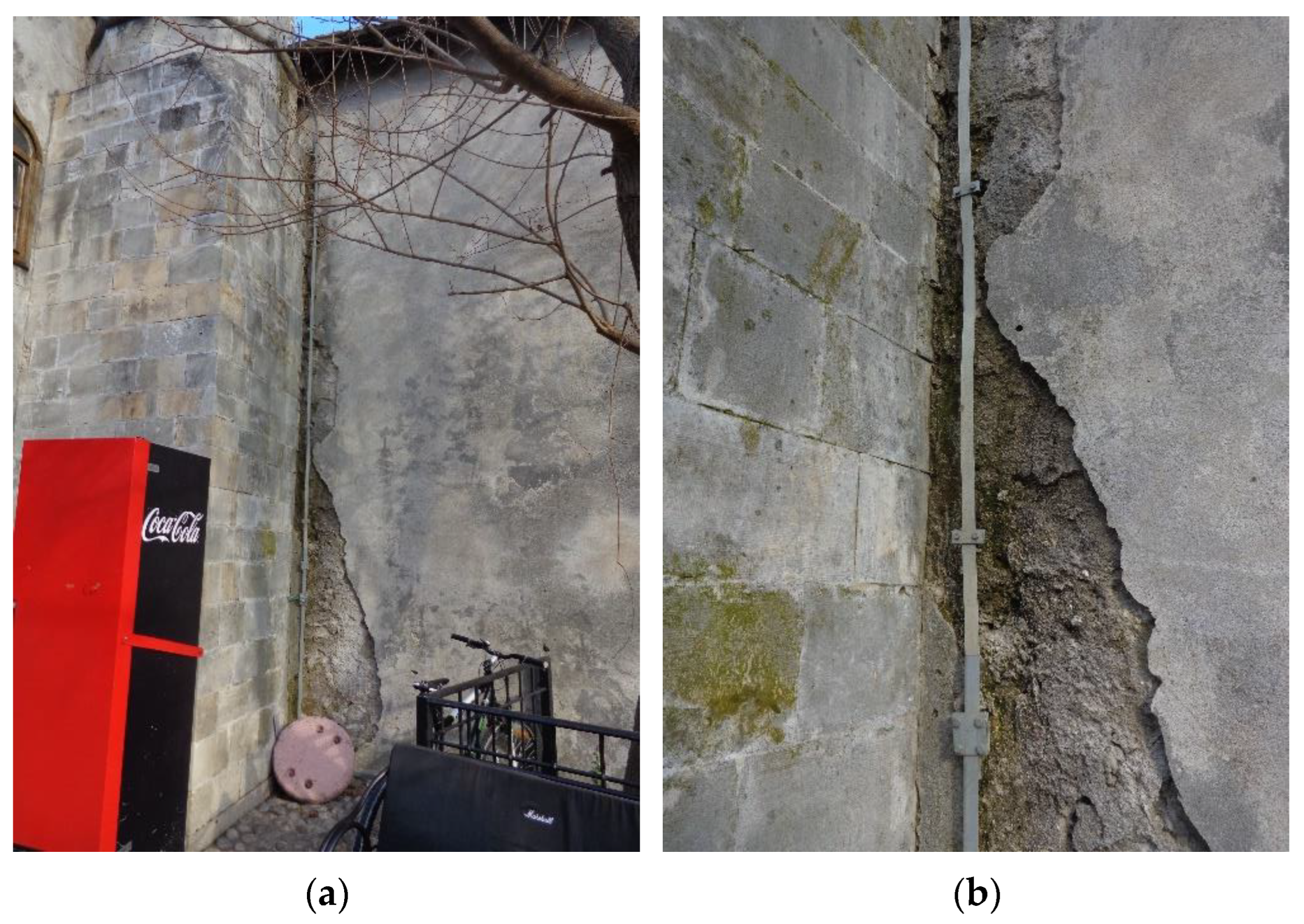
2.2. Geometry and Materials

A minaret is typically positioned at the right corner of the front façade. The base of the minaret can be separated from the mosque and in this way have its own foundation, or it can be built on the same foundations as the mosques. Regarding the minaret’s height, several typical parts may be noted, moving upwards (Figure 1b) [60]:
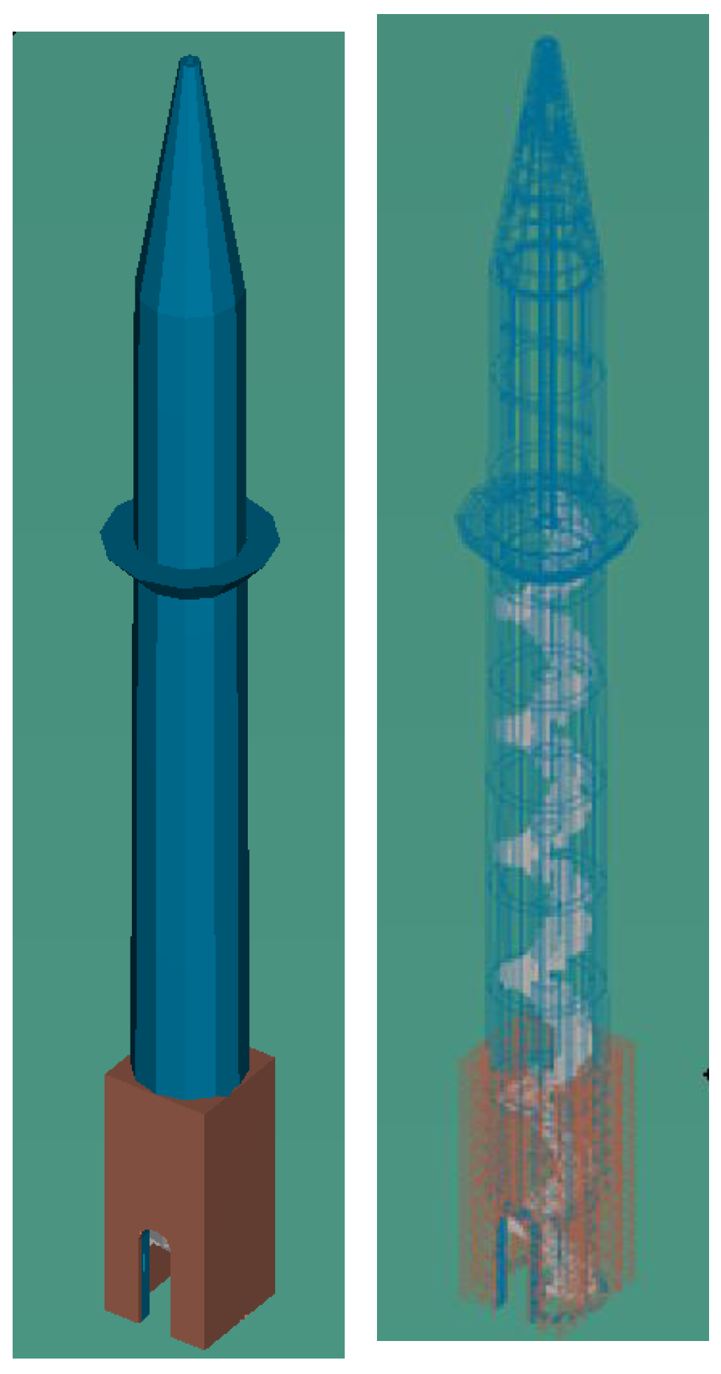
  • Part A: The base starts from the masonry footing which may be of polygonal or squared shape. The inner space of the base may be either hollow or filled with rubble masonry which depends on the starting height of the inner spiral staircase. This staircase is supported by a self-forming central column and by the minaret’s outer wall.
  • Part B is the longest part of the minaret. It is the central shaft where the outer shape is commonly a 12, 14, or 16-sided polygon and the inside is cylindrical.
  • Part C is the balcony (in Turkish “sherefe”) located at the end of part B. At this location, the inner spiral staircase ends.
  • Part D is the upper shaft. It is above the balcony with a door opening providing the exit to the balcony and is typically narrower than the central shaft.
The minaret ends with Part E which is a roofed part. It usually ends with a conical hood made of copper, lead, or confined stone slabs supported by the timber structure.
The materials which were selected for the construction of minarets were usually abundant in the local areas. Limestone ashlar was used for the construction of the mosque, the minaret, and the spiral stairs. The base wall is typically constructed as a three-leaf wall consisting of outer leaves made of ashlars and the inner core made of rubble stone with hydrated lime. For the connection of the ashlars, hydrated lime with thin-layer joints was used, while hydrated lime mortar with normal joints was used for the rubble stone. Horizontal connection was done by iron cramps, which were fixed by the lead poured at the upper side of blocks in previously prepared holes. Timber was used for the construction of the hood structure and it was covered with copper or lead sheets, or with shaped stone slabs, additionally confined with iron hoops.
Numerous structures in the Herzegovina region, are constructed of stone known as ‘‘tenelija” or ‘‘miljevina”. A significant number of experiments were conducted in order to determine the physical and mechanical properties of the ‘‘tenelija” stone due to its extensive applicability in the past and in the reconstruction of the famous Stari Most (Old Bridge) in Mostar [61]. Tenelija has been comprehensively investigated during the reconstruction of Stari Most and Karagöz Bey Mosque in Mostar [61,62]. The minaret of the Tabačica mosque was built from the same “tenelija” stone, from a quarry which is located in Mukoša near Mostar. The “tenelija” stone is very easy to shape, which is why more elegant, delicate, and refined buildings were built from it. However, due to its insufficient resistance to frost, the use of “tenelija” in the exterior is limited to the Mediterranean climate [63]. Masonry with “tenelija” is a tradition of the Mostar climate. During construction, “tenelija” can be found in various forms: in blocks weighing several tons (arch of the Old Bridge—Stari Most in Mostar), in smaller cubes and corners for building walls, cut slabs of various formats for interior and exterior cladding, in broken pieces as filling of walls, in various forms of tombstones, for columns and decorative masonry fences, and as a model stone for making sculptures [64].
Microscopic investigation of “tenelija” and “mukoša” blocks from the Stari Most has been conducted [65]. Besides the difference in texture and structure, these two domestic stone varieties differ in their mineralogical, petrographic, and chemical composition [61]. The most significant feature of “tenelija” limestone is its oolite structure [66]. Utilizing a scanning electron microscope (SEM) showed that “tenelija” stone is made of grain size up to 0.2–0.5 mm, classifying it into the oosparit stone class. In “tenelija” ooids are somewhat condensed and, in some places, there is a space between them [61].
For civil engineering applicability, the most important characteristics are physical and mechanical. Physical parameters of interest include, but are not limited to, density, open porosity, and water absorption, while mechanical properties of interest include, but not limited to, uniaxial compressive strength (UCS), tensile strength, Poisson’s ratio, and modulus of elasticity. Hahamović and Tufegdžić were the first researchers who tested the “tenelija” stone from the Mostar’s Stari Most. The density that was obtained was of a rather wide range, from 1700–2270 kg/m3, and 2070–2320 kg/m3, respectively [64]. After that, the most important in situ and laboratory tests were carried out during the renovation of the Stari Most in Mostar in the period from 1998 to 2002. Additional tests were performed in various periods and for various purposes. Some of the results are presented in Table 1. It should be noted that some tests were conducted in line with the ex-Yugoslavian standards and others in line with the European standards. Additionally, some researchers used cube samples and others cylinders, and the number of samples varied; thus, direct comparisons cannot be done. As can be seen, the results have a wide range. Some of the results are presented here for an informative purpose so that the readers can get an idea about the characteristics of this stone type.

3. On-Site Experimental Investigations

Geophysical tests, as part of the site investigation at the location of the minaret of the Tabačica mosque in Mostar, were carried out in July 2022 by Terra Compacta d.o.o. from Zagreb. The main goal of the research was to determine the fundamental vibration frequencies of the minaret and the surrounding soil using non-destructive methods and to determine the qualitative parameters of the mosque wall (speed of propagation of P-waves through the wall).

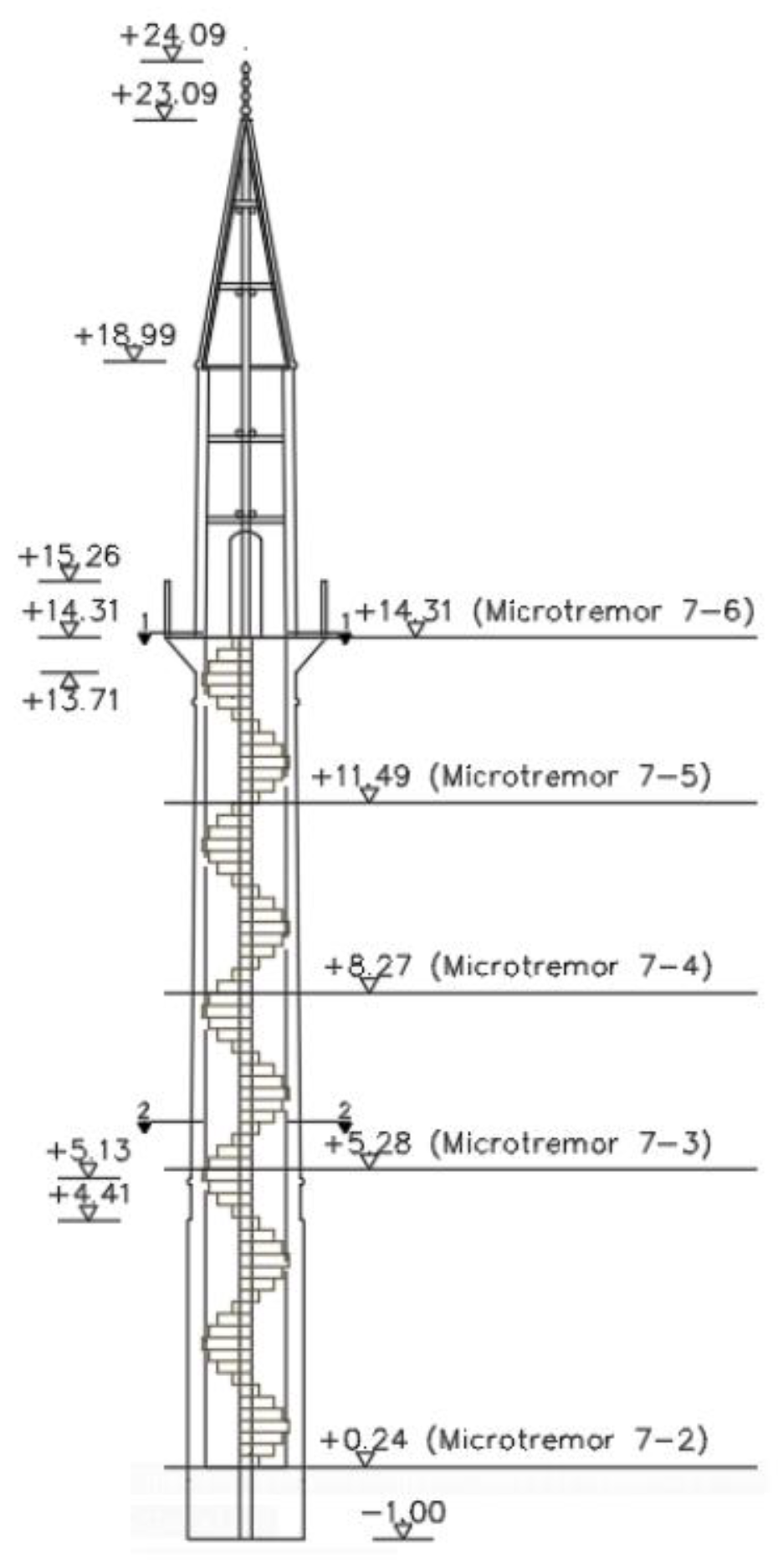
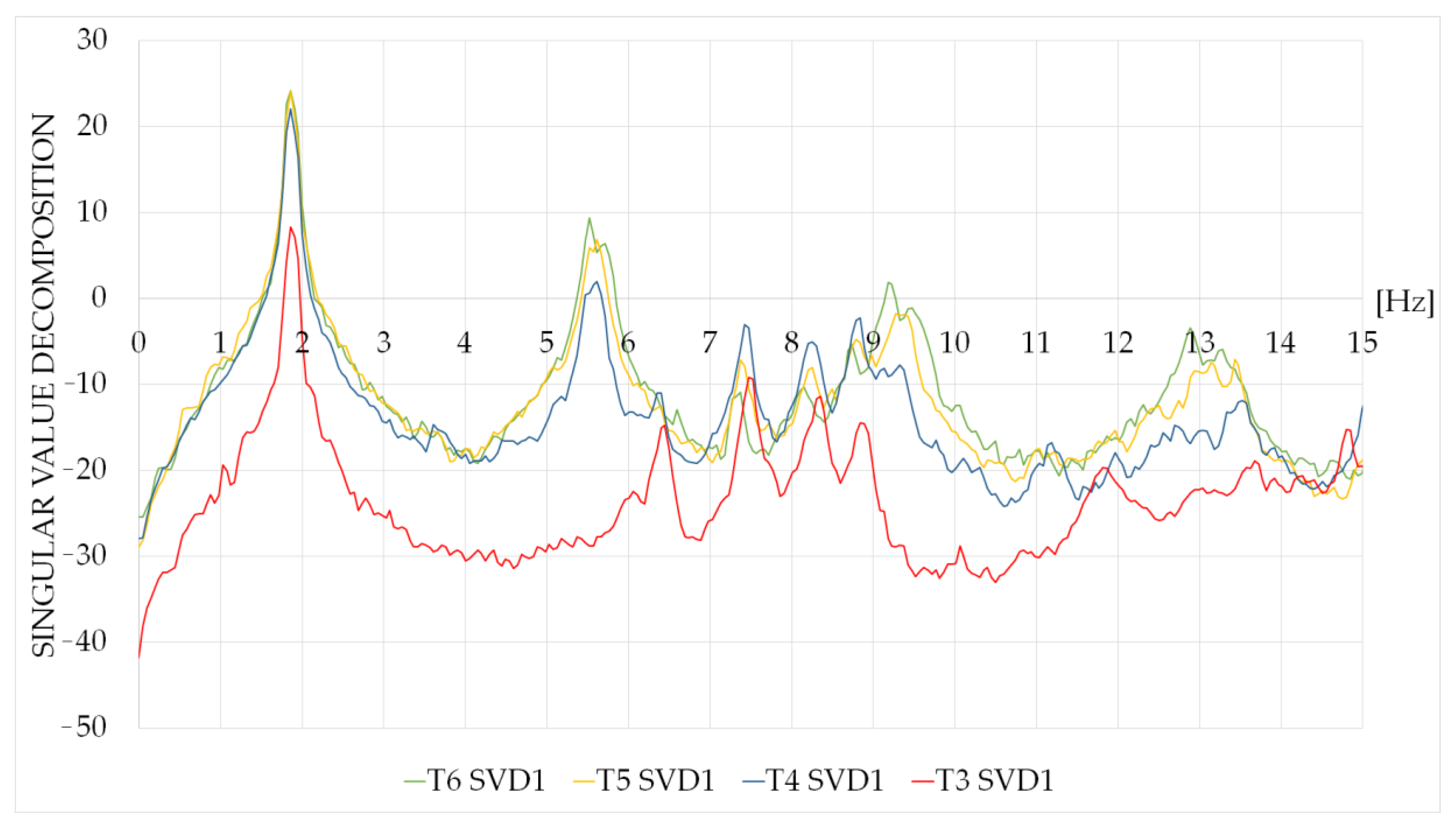
3.1. Determination of the Dynamic Characteristics

For the determination of the dynamic characteristics of the elaborated structure, two methods were applied, the horizontal to vertical spectral ratio (HVSR) method and the operational modal analysis (OMA). These parameters are necessary in order to calibrate the numerical model. Besides being non-destructive methods, the data is collected under the operational conditions of the structure.
The HVSR method was widely spread by Nakamura [69]; however, it was first developed by Nogoshi and Igarashi [70]. It is commonly used to estimate the resonant frequency of sedimentary layers on top of bedrock, by means of gathering the subsurface data from single station measurements by comparing the Fourier spectrum of horizontal components to the vertical components. This ratio is a function of the frequency that will produce the H/V curve. The biggest advantage of this method is the efficient estimation of the frequency at which the effect of seismic amplification will occur, being independent of input parameters. The method is almost independent of the source excitation and gives results for both earthquakes and microseismic tremors. This method was initially used by [69,71] to investigate the risk of seismicity in Japan. The usage of this method is limited to structures.
According to Nakamura [69], the microseismic tremors measured at a location are amplified by soft layers on a solid half-space. It is assumed that the horizontal components of microtremors are amplified by multiple reflections of transverse (S) waves in the upper soil layers, while the vertical component is amplified by multiple reflections of longitudinal (P) waves. It is assumed that P-wave amplification is not significant in the frequency range of interest; this assumption is satisfied in most cases.
The transfer function S T of surface layers is usually defined by the Equation (1):
S T   =   S HS S HB
where S HS and S HB are the horizontal tremor spectrum on the surface of the soil and the horizontal tremor spectrum incident from the substrate to surface layers (S—surface, B—bedrock). According to Nakamura [69], the S HS spectrum can be affected by Rayleigh waves propagating through the surface layers of the soil. The influence of Rayleigh waves should also be visible in the vertical component of a microseismic tremor on the surface, S VS , but it is not expected in the vertical component of a microseismic tremor at the level of the bedrock (because Rayleigh waves exist in the layer above the half-space—bedrock), S VB .
Assuming that the vertical component of motion is not amplified by surface layers, Nakamura [69] suggests that the influence of Rayleigh waves can be written in the form:
E S   =   S VS S VB .
If there is no Rayleigh wave, then E S   =   1 . Assuming that the influence of Rayleigh waves is equal for the vertical and horizontal components, Nakamura [69] suggests using a more reliable transfer function, S TT :
S TT   =   S HS S VS S HB S VB   =   R S R B . S T   =   S HS S HB
R S and R B are the spectral ratios of the horizontal and vertical components of the microseismic tremor at the surface ( R S ) and the bedrock level ( R B ) .
It has been experimentally shown that R B 1 is valid for wide frequency ranges. Therefore it follows that S TT   =   R S . This means that the transfer function can be estimated using only the tremor from the surface measurements; the vertical tremor on the surface maintains the horizontal tremor’s parameters.
Empirical research has shown that the spectral spike that appears on the HVSR curves is a very good estimate of the fundamental frequency of the location (soil or object) where the microseismic tremor is measured. The amplitude of the curve, in contrast, cannot be used as a measure of the seismic amplification of a site.
In the work conducted by Triwulan et al. [72], it has been stated that the HVSR method is able to describe the geological parameters of the elaborated area, the building’s structural characteristics and the correlation between them if the recording is done outside and inside the building. By this kind of application, they obtained the values of the natural frequency, the index of vulnerability, and the amplification factor. This means that the method may provide information regarding two very important things: to determine how far apart are the frequencies of the structure and the surface layer, and to determine the value of the amplitude of this frequency.
Luo et al. [73] studied how subway trains impact the ambient noise in reinforced concrete buildings. During the study, they were able to obtain information on the building’s eigenfrequency, the frequency that resulted from the train traffic near the elaborated building, and the fundamental frequency of the area where the structure is built.
Pentaris [74] used the HVSR method to obtain the resonance frequency of movement for two concrete buildings constructed of different materials and constructed in different years. It was noted that with the age of the building and crack visibility there is an increase in the values obtained by HVSR. As well, HVSR also indicated higher differential acceleration from floor to floor and higher structural vulnerability. Results indicate that the HVSR process using acceleration data proves to be an easy, cost-effective, and fast method for assessment of the fundamental frequency of structures; it also provides estimates on the building’s vulnerability, as an assessment method for building vulnerability estimation.
On the other hand, operational modal analysis (OMA) is frequently used for the determination of the natural frequencies, mode shapes, and damping of structures. In the literature, several names are allocated to this method, from output-only modal analysis, and ambient modal identification, to in-operation modal analysis [75]. Applying the enhanced frequency domain decomposition (EFDD) method provides higher accuracy in relation to the frequency domain decomposition (FDD). The EFDD is capable of estimating within a high degree of accuracy the closely spaced modes [75]. OMA has been used by numerous researchers for the determination of the dynamic characteristics of mosques and minarets. For the determination of the dynamic features of the Küçük Fatih mosque in Trabzon before and after the rehabilitation, the OMA was applied. After the strengthening, the structure became more rigid, with an increase of the frequencies [76]. Nohutcu et al. [77] with the application of OMA determined the frequency, damping ratios, and mode shapes of the Hafsa Sultan mosque in Manisa. The difference between the OMA and numerical results was up to 10% which was reduced in a stepwise manner by the reduction of the modulus of elasticity in the FEM model and in this way the model was calibrated. Demir et al. [78] improved the initial elasticity module of the historical Hafsa Sultan mosque by using the OMA method; once the model was calibrated, the damage to the structure was represented in a more accurate manner. Haciefendioğlu et al. [49] used OMA to determine how the type of soil impacts the natural frequencies of the scaled reinforced concrete minaret.
At the location of the Tabačica mosque, the microseismic tremors were measured at six locations within the minaret and the mosque, and the seventh was located in front of the mosque outside the influence of the building. The measurement in the mosque is marked as T-1. There were five measurements in the minaret, marked as T-2 at the base of the minaret, T-3 at the 25th stair, T-4 at the 40th stair, T-5 at the 56th stair, and T-6 at the 70th stair. Measurement T-7 was taken in the ground in front of the mosque outside the influence of the building (Figure 10 and Figure 11).
The measurements were performed with the equipment shown in Figure 12. The Seismograph GEA24 16077, compact-sized with 24 channels, was used. It is suitable for all applications and is very reliable. GEA24 can acquire data using geophones with any resonance frequency (even 1 Hz). In this specific case, a three-component geophone with a resonant frequency of 2 Hz was used.
Two microtremor measurements were performed at each location. The recordings were filtered with a low-pass filter that passes frequencies lower than 30 Hz. All three components of a single record are divided into time windows of 60 s with a five percent overlap, and the mean of the horizontal components is determined for each window; the spectrum of the mean of the horizontal components is divided by the spectrum of the vertical component. The results of individual windows are averaged. The resulting curve was then smoothed using the Konnoi–Ohmachi function [79] in the software Geopsy, developed in the frame of the SESAME program (Site Effects assessment using Ambient Excitations). The results are shown together with the standard deviations (dashed line in Figure 13).
Data were also elaborated by employing an OMA-specific analysis software [81], relying both on time domain—UPC SSI—and frequency—sEFDD—based identification methods. From the analyses carried out, there emerges a strict coupling of the bending modes of the minaret. The first frequency of the minaret using the OMA method test results was 1.85 Hz in all test setups (bending in the Y direction), very close to the second identified frequency, equal to 1.91 Hz (bending in the X direction), while the second bendings were found, respectively, at about 5.53 and 5.67 Hz. A supposed torsional mode was located at 7.40 Hz, and the successive coupled bending modes were identified at 9.20 (Y) and 9.40 (X) Hz, and again at 12.90 (Y) and 13.40 (X) Hz. Since no reference sensors were employed, it is not possible to present the graphical depiction of the identified modes. Results are reported as a graph in the frequency domain (Singular Value Decomposition—Figure 14) and numerically in Table 2 The average damping values for F1 to F4 are consistent with the level of vibration and are within the reported ranges under operational conditions as defined in manuals for civil engineering and seismic design [82,83]. A significant value of damping has been detected for the torsional mode indicating that it may be affected by biases, as reported by Karatzetzou et al. [84].
In addition to the values indicated in Figure 13, the resonance at approximately 1.93 Hz is visible also in the HVSR curves at T-2, T-3, and T4. The first and second frequencies according to the OMA method are 1.85 Hz and 1.91 Hz, respectively.

3.2. Sonic Pulse Velocity Test (SPVT)

The second test that was conducted was the sonic velocity test (SPVT). The SPVT is based on measuring the travel time of elastic longitudinal P-waves (acoustic waves, “sonic waves”) through a given material. The speed of acoustic waves is determined according to the length of the path and the calculated propagation time of the wave. The obtained results provide useful information about the quality and consistency of the investigated element. The speed is affected by the composition of the material as well as the presence of substances, voids, and damage. It is a non-destructive method frequently used for diagnosing existing masonry and evaluating the effectiveness of interventions.
As per Binda et al. [85], there are two aims for the implementation of the sonic tests in masonry structures. Based on the morphology of the wall section it is possible to quantify masonry, as well as locate cracks and determine the damage pattern. This method enables the detection of voids and eventual flaws in the masonry. Once a structure is repaired, the sonic tests provide information that can be used to check the effectiveness of the remedial injection measures. The pulse sonic velocity is individual for each masonry typology and no generalization is possible. These tests provide qualitative information and are combined with other non-destructive tests and minor-destructive tests.
Sonic testing could not be performed on the walls of the minaret due to inaccessibility, so the testing was performed on the wall of the mosque, which is built from the same stone as the minaret and built in the same way as the base of the minaret. The testing was carried out in a grid of 0.9 × 0.9 m, with 16 test micro-locations spaced at 30 cm along the horizontal and vertical axis (Figure 15).
The emission of acoustic waves was done with a rubber hammer. The hammer applies an impulse on the surface of the wall and generates a sonic wave. The arrival times of the P-waves were recorded on an accelerometer which is connected to the instrument on the opposite side of the wall (Figure 16 and Figure 17). This enables the transformation of the mechanical energy into acoustic-vibration energy and enables the wave to propagate through the material. A receiving sensor (monoaxial accelerometer) is responsible for recording and transmitting to the acquisition system the response of the material to the propagation of the signal in the section.
Evaluation of the characteristics of the walls of historic masonry buildings by using a sonic pulse velocity method has been performed by numerous researchers, see, e.g., [86,87,88,89,90].
The results of the SPVT test are shown in Table 3 and Figure 18. The table contains the serial numbers of the recording points with the associated digital record number; the wall thickness in cm; X and Y coordinates of the position of initiating the elastic wave; and recording with the accelerometer, propagation time, and calculated speed of P-wave propagation through the wall.
Figure 18 shows the distribution of P-wave propagation speeds through the examined wall. Velocity values are approximately in the range of 3800 to 5300 m/s, which indicates the high compactness and quality of the wall. Slightly lower velocities (3800 to 4500 m/s) were found in the first half of the wall (from the height Y = 0 to about 50 cm), which indicates that sporadic, localized discontinuities are possible in that part of the wall, or that the lower part of the wall is made of material with different characteristics.

4. Nonlinear Dynamic Structural Analysis

In this specific case, it was decided to use the nonlinear model that is based on AEM, a derivative of the FEM and DEM which is utilized in the Extreme Loading for Structures (ELS) software. With this software, it is possible to study the behavior of structures through the continuum phase and the discrete phase of loading, which is of the utmost importance when the structure collapses. Seismic assessment of existing structures using ELS software was done by several researchers [27,91,92,93].
In AEM, along their connecting surfaces, the elements are connected with a set of normal and shear springs that are responsible for the transfer of normal and shear stresses among adjacent elements. Each spring denotes stresses and deformations of a certain volume of material. Two elements are separated from each other if the springs connecting them are broken (failed). In AEM, elements may automatically be separated, re-contacted, or contacted with other elements. When elements are connected with the contact springs at contact points, different types of element contact can be formulated as shown in Figure 19a,b [27].
The AEM is found to be much more user-friendly for modeling solid elements for non-linear structural analysis than the FEM. First of all, nodal completability is not needed which makes meshing much easier. AEM connects elements through springs which are located between the solid elements. There is no need for an a priori definition of hinge locations. This means that the AEM gives the plastic hinges as results and not as input data. Modeling of masonry units is very easy and all types of masonry patterns and mortar joints can be implemented. This technology allows modeling of the existing structures with true detailing of connections. This includes applying weakening at sections with existing cracks (crack width and custom shapes of cracks). Due to all the above, it was decided that the AEM is the most representative numerical tool for this research.

4.1. Description of the Structural Model

The minaret of Tabačica mosque was modeled as a stand-alone structure. According to earlier research by Karatzetzou et al. [84] analyzing the dynamic properties of the Suleiman Mosque in the city of Rhodes in Greece, it was concluded that there were no significant changes in the frequency values between the model of the minaret only and the model of the minaret together with the mosque.
The minaret is made of stone elements which are disseized by the number of small elements connected with mortar springs at the interface between the elements. For the units, the principal stress failure criterion is implemented while Mohr–Coulomb’s friction model with tension cut-off is used to represent the interface behavior with mortar. The shear behavior in the tensile regime is represented through the softening regime once the cohesion is lost and debonding takes place. The elements are connected by the strings and the constitutive properties of the area material in the particular area of the representations are formulated in these springs. Frequencies were extracted from a linear model, while the material nonlinearity was taken into account in the time-history analysis.
The minaret of Tabačica was modeled in ELS software [94] and it has a total of 23,302 quadrilateral elements and 1,856,800 springs. The exact dimensions were determined by on-site measurements of the minaret. The 3D models developed in the ELS software are shown in Figure 20. The stairs were taken into account in the model and drawn together with the outer wall to avoid possible problems in the mesh creation and intersection. The mechanical properties of the minaret are shown in Table 4.
The natural frequencies of a structure are obtained as the result of modal analysis and are presented in Table 5.
The first period obtained for the minaret of the Tabačica mosque is compared with the values obtained by four empirical formulas as suggested in the literature [95,96,97,98,99,100]. The empirical formulas are shown in Table 6 and it can be concluded that the first period of the minaret is in good agreement with the empirical formulas provided in the literature.
The largest difference between the experimental and numerical frequencies is about 9.54% for the first five modes (Table 7), which can be considered acceptable.
The mode shapes obtained from the analysis in the software ELS of the minaret are shown in Figure 21. The first four mode shapes are longitudinal, but in the fifth mode, torsion has occurred, as can be seen in Figure 21. In the work done by Işık et al. [44], Işık et al. [45], and Mutlu and Sahin [34], the fifth mode was torsional as well. Ural and Çelik [101] investigated the seismic behavior of seven single balcony minarets. In this case as well, the fifth mode was one of torsion. Interestingly, the analysis of five timber minarets investigated by Bağbancı et al. [42] revealed the torsional mode as the fifth mode. In the work of Altiok and Demir [50] the torsional mode was identified as the sixth. For the reinforced concrete minaret, located in Islamabad, the dominant-torsional was also identified in the fifth position [51].

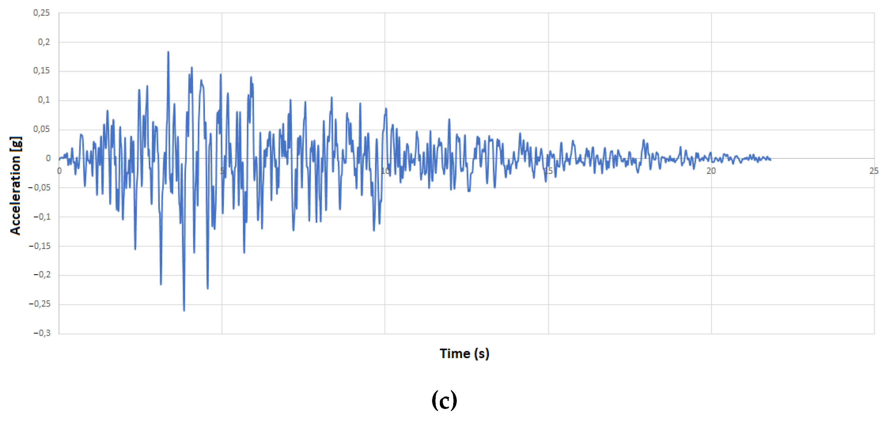
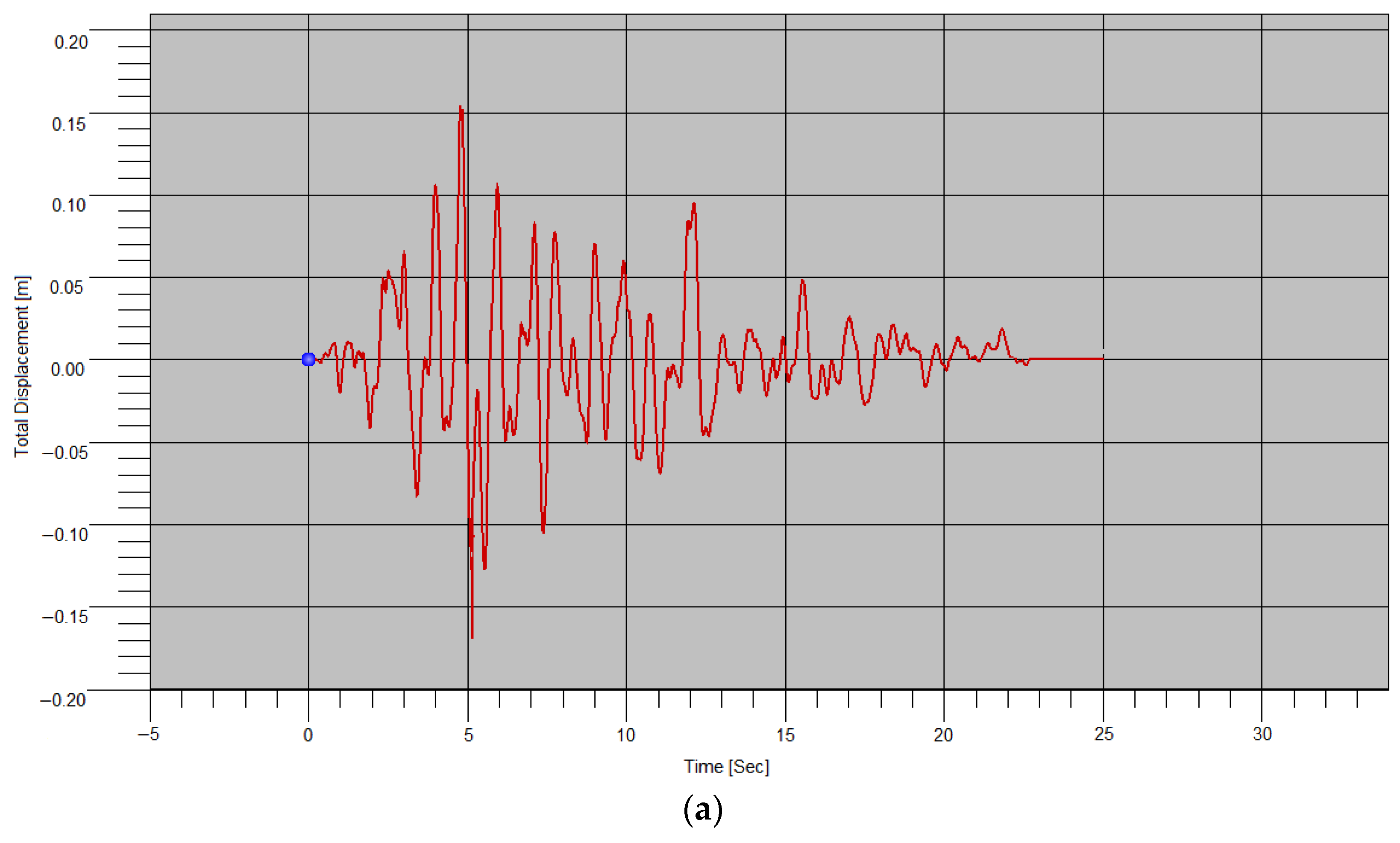
4.2. Non-Linear Time History Analysis

In the nonlinear analysis of the earthquake records, two main approaches for the generation of an accelerogram can be used; real earthquake records or synthetic (artificial accelerograms). Very often artificial accelerograms are used for numerical simulations and the same will be applied in this case. According to Eurocode 8 [102], several requirements have to be fulfilled for seismic analysis. It is necessary to use at least three accelerograms and the same accelerogram cannot be implemented at the same time in both horizontal directions. In the case when site-specific data are not available, the minimum duration of the stationary part of the accelerograms (Ts) should be 10 s, which is the case here as well.
The artificial acceleration records were used to determine the seismic resistance of the Tabačica mosque minaret. According to the National Annex of Bosnia and Herzegovina [58] and the accompanying interactive seismic map of Bosnia and Herzegovina, the peak ground acceleration (PGA) for Mostar is 0.26 g for the return period of 475 years. Taking this data into account, together with the soil type B and 5% damping, three sets of three artificial accelerograms were obtained as presented in Figure 22. An example of the artificial accelerograms are applied for X, Y, and Z directions.
Nonlinear analysis of the minaret under the first set of accelerograms shows that the maximum lateral displacement values are 16.2 cm and 15.3 cm in the X and Y directions, respectively (Figure 23 a and b). The total response of the structure is the highest in the range from around 2.5 s to 6 s. It is interesting to note that in the range from eight to 15 s, there is a reduction of the displacement, and then at 15 s the displacement reaches the value of 9.02 cm.
The critical maximum and minimum principal stress contours under the earthquake ground motion are presented in Figure 24 a and b respectively.
Analyzing the distribution of the principal stresses, maximum and minimum principal stresses occurred in the same location, above the transition from the base to the shaft, and were obtained as 2.186 MPa and 1.706 MPa, respectively (Figure 24a,b). The concentration of stresses is located at the contact of the base and the shaft (transitional region) as indicated in [95], which is usually the location where the failure of the minaret is to be expected [54,103,104,105].
The time histories of total displacements above the transition from the base to the shaft (Figure 25a) are presented in Figure 25b. The largest value of the displacement is 0.0164 cm at 4.81 s. The same response pattern is observed in the case of the top displacement of the minaret. Formation of the horizontal crack is observed at the transition from the base to the shaft (Figure 25c).
The total displacement of the top minaret element during the two other artificial accelerograms is shown in Figure 26a,b.
For the second set of accelerograms, slightly lower values are obtained. The maximum lateral displacement value for the X direction is 15.1 cm and 15.2 cm for the Y direction. For the third set of accelerograms, similar values are obtained as for the first set, except that the displacement in the Y direction is higher than the displacement in the X direction. The maximum lateral displacement value for the X direction is 15.7 cm and 16.1 cm for the Y direction. Maximum X and Y displacements for all three sets of accelerograms are shown in Table 8.
The values of principal stresses for the second and third sets are shown in Table 9. The concentration of stresses is located at the contact of the base and the shaft (transitional region).
In the aftermath of the 1999 Duzce/Bolu earthquake, Doğangün et al. [54] reported the collapse of two more than 500-years old minarets at the location of the transition segments due to extreme values of tensile stresses at these locations. Çaktı et al. [33] identified three zones with potential excessive deformation and stresses. Two locations were identified in the transition segments and the third location was identified at the mid-height of the body. The concentration of the tensile stresses was noted in the transition zone between the square base and the circular section. The maximum tensile stress values were in the range of 2.17 MPa to 10.46 MPa, which was significantly above the tensile strength of the minarets (around 0.4 MPa) [101]. The same location of the damage was determined by Döven et al. [36]. In the aftermath of the 2020 earthquake that hit the Sivrice district of Elazig city, damage was noted on the transition section in several minarets [47], as well as propagation of cracks and in some cases even collapse in the cone section and cracks in the pulpit section were detected. Transition zones, as one of the most vulnerable regions, were also identified by Altiok and Demir [50] in their study of one of the most famous minarets in Turkey, the minaret of the Lala Mehmet Pasha Mosque. During the detailed elaboration and assessment of the Ulu Mosque’s minaret, Işık et al. [45] identified the concentration of stresses at the location of the balcony and the connection of the squared base and circular body of the minaret. It was interesting to note that the obtained stresses once the structure was exposed to earthquake actions were, as per new Turkish regulations, lower than the allowable Bilitis stone’s strength.
This may be connected to the change in the cross-section and the difference in the stiffness. Additionally, the second concentration is located at the second transition zone where the balcony is located, as found by [95]. It is likely that under much stronger earthquakes, the minaret will be significantly damaged in the transitional region.

5. Conclusions

The first frequency of the minaret obtained by the ambient vibration test is 1.85 Hz, and the one obtained by the modal analysis is 1.96 Hz. There are also four empirical formulas for calculating the first period of vibration for slender structures. It may be concluded that there is a good match between the results of the on-site investigation and the modal analysis. For the first time, two methods were used for the determination of the eigen frequency, the horizontal-to-vertical spectral ratio (HVSR) method and the operational modal analysis (OMA). However, there is a need for fine calibration of the model in order to get the results even closer to those obtained by on-site investigation. In this connection, it is necessary to perform the parametric analysis to determine the influence of certain factors. These factors may include material properties, connection joints, attachment of the minaret to the mosque building, foundation soil, etc. It has been indicated that there is a good agreement between the different methods utilized for the determination of the dynamic characteristics.
The on-site investigation included a qualitative assessment of the three-leaf masonry wall of the mosque building by sonic pulse velocity test. Obtained velocities between 3800 and 5300 m/s indicate a solid quality of the masonry wall which is similar to the one at the base of the minaret.
The nonlinear analysis of three sets of accelerograms revealed and confirmed once again the weak point of the minaret being the transitional regions, the location where geometry changes from a rectangular to a circular shape, and the location of the balcony. Above the transition from the base to the shaft, for all three sets of accelerograms, a horizontal crack appears after the earthquake. Under stronger earthquakes, this crack would widen and other cracks would appear, which potentially would lead to the collapse of the minaret. Tabačica minaret is vulnerable to earthquakes of moderate intensity due to its slenderness and material characteristics.
The elegant pencil-shaped minarets built in classical Ottoman style are susceptible to damage by moderate earthquakes due to their particular geometry and height, in addition to the deterioration of their construction materials as a result of the aging process and environmental conditions.
In addition to the aforementioned parametric analysis, further work on the subject should comprise the structural analysis for stronger seismic excitation with vanishing tensile strength of masonry. Special care regarding the possible change of the structural system should be taken in case the strengthening of the minaret is considered.

Author Contributions

Conceptualization, N.A.; methodology, N.A.; software, F.T. and N.A.; validation, N.A., F.T. and F.C.; formal analysis, N.A., F.T. and F.C.; investigation, M.H. and F.T.; resources, F.T., M.H. and N.A.; writing—original draft preparation, N.A. and F.T.; writing—review and editing, N.A., F.C. and M.H.; visualization, N.A.; supervision, N.A., M.H. and F.C.; project administration, N.A. and F.T.; funding acquisition, N.A. and F.T. All authors have read and agreed to the published version of the manuscript.

Funding

This research was funded by the Federal Ministry of Education and Science, Federation of Bosnia and Herzegovina, Bosnia and Herzegovina in 2021 (No.05-35-1935-1/21), Project “Analysis of the bearing capacity of masonry minarets under seismic action” acronym ANZMSD.

Institutional Review Board Statement

Not applicable.

Informed Consent Statement

Not applicable.

Data Availability Statement

The data are not publicly available due to privacy reasons.

Acknowledgments

The authors give special thanks to the Federal Ministry of Education and Science, Federation of Bosnia and Herzegovina, Bosnia and Herzegovina for its financial support for this project.

Conflicts of Interest

The authors declare no conflict of interest.

References

  1. Hadzima-Nyarko, M.; Ademović, N.; Pavić, G.; Sipos, T.K. Strengthening techniques for masonry structures of cultural heritage according to recent Croatian provisions. Earthq. Struct. 2018, 15, 473–485. [Google Scholar] [CrossRef]
  2. D’Altri, A.M.; Sarhosis, V.; Milani, G.; Rots, J.; Cattari, S.; Lagomarsino, E.; Sacco, A.; Tralli, G.; Castellazi, G.; de Miranda, S. Chapter 1—A review of numerical models for masonry structures. In Woodhead Publishing Series in Civil and Structural Engineering, Numerical Modeling of Masonry and Historical Structures; Woodhead Publishing: Kidlington, UK, 2019; pp. 3–53. [Google Scholar] [CrossRef]
  3. Page, A. Finite element model for masonry. J. Struct. Div. 1978, 104, 1267–1285. Available online: https://ascelibrary.org/doi/10.1061/JSDEAG.0005406 (accessed on 3 November 2022). [CrossRef]
  4. Çaktı, E.; Saygili, Ö.; Lemos, J.V.; Oliveira, C.S. Discrete element modeling of a scaled masonry structure and its validation. Eng. Struct. 2016, 126, 224–236. [Google Scholar] [CrossRef]
  5. Rafiee, A.; Vinches, M. Mechanical behaviour of a stone masonry bridge assessed using an implicit discrete element method. Eng. Struct. 2013, 48, 739–749. [Google Scholar] [CrossRef]
  6. Pantò, B.; Cannizzaro, F.; Caddemi, S.; Caliò, I. 3D macro-element modelling approach for seismic assessment of historical masonry churches. Adv. Eng. Softw. 2016, 97, 40–59. [Google Scholar] [CrossRef]
  7. Abbati, S.D.; D’Altri, A.M.; Ottonelli, D.; Castellazzi, G. Seismic assessment of interacting structural units in complex historic masonry constructions by nonlinear static analyses. Comput. Struct. 2019, 213, 51–71. [Google Scholar] [CrossRef]
  8. Bartoli, G.; Betti, M.; Vignoli, A. A numerical study on seismic risk assessment of historic masonry towers: A case study in San Gimignano. Bull. Earthq. Eng. 2016, 14, 1475–1518. [Google Scholar] [CrossRef]
  9. Castellazzi, M.; D’Altri, A.M.; de Miranda, S.; Chiozzi, A.; Tralli, A. Numerical insights on the seismic behavior of a non-isolated historical masonry tower. Bull. Earthq. Eng. 2018, 16, 933–961. [Google Scholar] [CrossRef]
  10. Milani, G.; Shehu, R.; Valente, M. Seismic Assessment of Masonry Towers by means of Nonlinear Static Procedures. In Proceedings of the X International Conference on Structural Dynamics (EURODYN 2017), Rome, Italy, 10–13 September 2017; Volume 199, pp. 266–271. [Google Scholar] [CrossRef]
  11. Micelli, F.; Cascardi, A.; Aiello, M.A. Seismic Capacity Estimation of a Masonry Bell-Tower with Verticality Imperfection Detected by a Drone-Assisted Survey. Infrastructures 2020, 5, 72. [Google Scholar] [CrossRef]
  12. Torelli, G.; D’Ayala, D.; Betti, M.; Bartoli, G. Analytical and numerical seismic assessment of heritage masonry towers. Bull. Earthq. Eng. 2020, 18, 969–1008. [Google Scholar] [CrossRef] [Green Version]
  13. de Felice, G. Out-of-Plane Seismic Capacity of Masonry Depending on Wall Section Morphology. Int. J. Archit. Herit. 2011, 5, 466–482. [Google Scholar] [CrossRef]
  14. Pulatsu, B.; Bretas, E.M.; Lourenco, P.B. Discrete element modeling of masonry structures: Validation and application. Earthq. Struct. 2016, 2016, 563–582. [Google Scholar] [CrossRef]
  15. Lemos, J.V. Discrete Element Modeling of the Seismic Behavior of Masonry Construction. Buildings 2019, 9, 43. [Google Scholar] [CrossRef] [Green Version]
  16. Sarhosis, V.; Sheng, Y. Identification of material parameters for low bond strength masonry. Eng. Struct. 2014, 60, 100–110. [Google Scholar] [CrossRef] [Green Version]
  17. Sarhosis, V.; Garrity, S.W.; Sheng, Y. Influence of brick–mortar interface on the mechanical behaviour of low bond strength masonry brickwork lintels. Eng. Struct. 2015, 88, 1–11. [Google Scholar] [CrossRef] [Green Version]
  18. Giamundo, V.; Sarhosis, V.; Lignola, G.P.; Sheng, Y.; Manfredi, G. Evaluation of different computational modelling strategies for the analysis of low strength masonry structures. Eng. Struct. 2014, 73, 160–169. [Google Scholar] [CrossRef] [Green Version]
  19. Mohebkhah, A.; Sarhosis, V. Discrete Element Modeling of Masonry-Infilled Frames. In Computational Modeling of Masonry Structures Using the Discrete Element Method; IGI Global: Hershey, PA, USA, 2016; pp. 200–235. [Google Scholar] [CrossRef] [Green Version]
  20. Dimitri, R.; Zavarise, G. Numerical Study of Discrete Masonry Structures under Static and Dynamic Loading. In Computational Modeling of Masonry Structures Using the Discrete Element Method; IGI Global: Hershey, PA, USA, 2016; pp. 254–291. [Google Scholar] [CrossRef]
  21. Alexakis, H.; Makris, N. Validation of the Discrete Element Method for the Limit Stability Analysis of Masonry Arches. In Computational Modeling of Masonry Structures Using the Discrete Element Method; IGI Global: Hershey, PA, USA, 2016; pp. 292–325. [Google Scholar] [CrossRef]
  22. Drei, A.; Milani, G.; Sincraian, G. Application of DEM to Historic Masonries, Two Case-Studies in Portugal and Italy: Aguas Livres Aqueduct and Arch-Tympana of a Church. In Computational Modeling of Masonry Structures Using the Discrete Element Method; IGI Global: Hershey, PA, USA, 2016; p. 41. [Google Scholar] [CrossRef]
  23. Meguro, K.; Tagel-Din, H. Applied Element Method For Structural Analysis: Theory and application for linear materials. Struct. Eng. Earthq. Eng. JSCE 2000, 17, 21–35. [Google Scholar] [CrossRef] [Green Version]
  24. Meguro, K.; Tagel-Din, H. Applied Element Simulation of RC Structures under Cyclic Loading. J. Struct. Eng. 2001, 127, 1295–1305. [Google Scholar] [CrossRef]
  25. Meguro, K.; Tagel-Din, H. Applied Element Method Used for Large Displacement Structural Analysis. J. Nat. Disaster Sci. 2002, 24, 25–34. [Google Scholar]
  26. Malomo, D.; Pinho, R.; Penna, A. Applied Element Modelling of the Dynamic Response of a Full-Scale Clay Brick Masonry Building Specimen with Flexible Diaphragms. Int. J. Archit. Herit. 2020, 14, 1484–1501. [Google Scholar] [CrossRef]
  27. Salem, H.; Gregori, A.; Helmy, H.; Fassieh, K.; Tagel-Din, H. Seismic Assessment of the Damaged Margherita Palace. In Proceedings of the 16th World Congress on Earthquake Engineering (16WCEE), Santiago, Chile, 9–13 January 2017; Available online: https://www.wcee.nicee.org/wcee/article/16WCEE/WCEE2017-2399.pdf (accessed on 1 November 2022).
  28. Diana, L.; Reuland, Y.; Lestuzzi, P. Seismic Vulnerability Assessment of “Sion Cathedral” (Switzerland): An Integrated Approach to Detect and Evaluate Local Collapse Mechanisms in Heritage Buildings. In Proceedings of the 3rd International Conference on Protection of Historical Constructions, PROHITECH’17, Lisbon, Portugal, 12–15 July 2017. [Google Scholar]
  29. Karbassi, A.; Nollet, M.J. Performance-Based Seismic Vulnerability Evaluation of Masonry Buildings Using Applied Element Method in a Nonlinear Dynamic-Based Analytical Procedure. Earthq. Spectra 2013, 29, 399–426. [Google Scholar] [CrossRef]
  30. Zerin, A.I.; Hosoda, A.; Salem, H.; Amanat, K.M. Seismic Performance Evaluation of Masonry Infilled Reinforced Concrete Buildings Utilizing Verified Masonry Properties in Applied Element Method. J. Adv. Concr. Technol. 2017, 15, 227–243. [Google Scholar] [CrossRef] [Green Version]
  31. Clotaire, M.; Karbassi, A.; Lestuzzi, P. Evaluation of the seismic retrofitting of an unreinforced masonry building using numerical modeling and ambient vibration measurements. Eng. Struct. 2018, 158, 124–135. [Google Scholar] [CrossRef]
  32. Oliveira, C.S.; Çaktı, E.; Stengel, D.; Branco, M. Minaret Behaviour under Earthquake Loading: The Case of Historical Istanbul. Earthq. Eng. Struct. Dyn. 2012, 41, 19–39. [Google Scholar] [CrossRef]
  33. Çaktı, E.; Oliveira, S.; Carlos, S.; Lemos, J.V.; Özden, S.; Serkan, G.; Esra, Z. Earthquake behavior of historical minarets in Istanbul. In Proceedings of the 4th ECCOMAS Thematic Conference on Computational Methods in Structural Dynamics and Earthquake Engineering, Kos Island, Greece, 12–14 June 2013. [Google Scholar]
  34. Mutlu, Ö.; Sahin, A. Investigating the effect of modeling approaches on earthquake behavior of historical masonry Minarets-Bursa, Grand Mosque case study. Sigma 2016, 7, 123–136. [Google Scholar]
  35. Livaoğlu, R.; Baştürk, M.H.; Doğangün, A.; Serhatoğlu, C. Effect of geometric properties on dynamic behavior of historic masonry minaret. KSCE J. Civ. Eng. 2016, 20, 2392–2402. [Google Scholar] [CrossRef]
  36. Döven, M.S.; Serhatoğlu, C.; Kaplan, O.; Livaoğlu, R. Dynamic behaviour change of Kütahya Yeşil minaret with covered and open balcony architecture. Eskişehir Tech. Univ. J. Sci. Technol. B Theor. Sci. 2018, 6, 192–203. [Google Scholar]
  37. Portioli, F.; Mammana, O.; Landolfo, R.; Mazzolani, F.M.; Krstevska, L.; Tashkov, L.; Gramatikov, K. Seismic Retrofitting of Mustafa Pasha Mosque in Skopje: Finite Element Analysis. J. Earthq. Eng. 2011, 15, 620–639. [Google Scholar] [CrossRef]
  38. Krstevska, L.; Tashkov, L.; Gramatikov, K.; Landolfo, R.; Mammana, O.; Portioli, F.; Mazzolani, F.M. Large-scale experimental investigation on Mustafa-Pasha mosque. J. Earthq. Eng. 2010, 14, 842–873. [Google Scholar] [CrossRef]
  39. Tashkov, L.A.; Krstevska, L.S.; Safak, E.; Çakti, E.; Edincliler, A.; Erdik, M. Comparative study of large and medium scale mosque models tested on seismic shaking table. In Proceedings of the 15th World Conference on Earthquake Engineering 2012, Lisbon, Portugal, 24–28 September 2012. [Google Scholar]
  40. Yekrangnia, M.; Mobarake, A.A. Restoration of Historical Al-Askari Shrine. II: Vulnerability Assessment by Numerical Simulation. J. Perform. Constr. Facil. 2016, 30, 04015031. [Google Scholar] [CrossRef]
  41. Ebrahimiyan, M.; Golabchi, M.; Yekrangnia, M. Field Observation and Vulnerability Assessment of Gonbad-e Qābus. J. Archit. Eng. 2017, 23, 05017008. [Google Scholar] [CrossRef]
  42. Bağbancı, M.B.; Bağbancı, K.Ö. The Effects of Construction Techniques and Geometrical Properties on the Dynamic Behavior of Historic Timber Minarets in Sakarya, Turkey. Shock. Vib. 2018, 2018, 9853896. [Google Scholar] [CrossRef] [Green Version]
  43. Boğaziçi University Kandilli Observatory and Earthquake, Research Institute. 15 OCAK 2023 ML = 4.9 Kavakköy Sivrice Elaziğ Depremi. 2017. Available online: http://www.koeri.boun.edu.tr/sismo/2/deprem-bilgileri/buyuk-depremler/ (accessed on 5 December 2022).
  44. Işık, E.; Harirchian, E.; Arkan, E.; Avcil, F.; Günay, M. Structural Analysis of Five Historical Minarets in Bitlis (Turkey). Buildings 2022, 12, 159. [Google Scholar] [CrossRef]
  45. Işık, E.; Avcil, F.; Harirchian, E.; Arkan, E.; Bilgin, H.; Özmen, H.B. Architectural Characteristics and Seismic Vulnerability Assessment of a Historical Masonry Minaret under Different Seismic Risks and Probabilities of Exceedance. Buildings 2022, 12, 1200. [Google Scholar] [CrossRef]
  46. Gunes, B.; Cosgun, T.; Sayin, B.; Ceylan, O.; Mangir, A.; Gumusdag, G. Seismic assessment of a reconstructed historic masonry structure: A case study on the ruins of Bigali castle mosque built in the early 1800s. J. Build. Eng. 2021, 39, 102240. [Google Scholar] [CrossRef]
  47. Yetkin, M.; Dedeoğlu, ĺ.Ö.; Calayır, Y. Investigation and assessment of damages in the minarets existing at Elazig after 24 January 2020 Sivrice earthquake. Fırat Univ. J. Eng. Sci. 2021, 33, 379–389. [Google Scholar]
  48. Casolo, S.; Diana, V.; Uva, G. Influence of soil deformability on the seismic response of a masonry tower. Bull. Earthq. Eng. 2017, 15, 1991–2014. [Google Scholar] [CrossRef]
  49. Haciefendioğlu, K.; Alpaslan, E.; Demir, G.; Dinc, B.; Birinci, F. Experimental modal investigation of scaled minaret embedded in different soil types. Gradevinar 2018, 70, 201–212. [Google Scholar] [CrossRef]
  50. Altiok, T.Y.; Demir, A. Collapse mechanism estimation of a historical masonry minaret considered soil-structure interaction. Earthq. Struct. 2021, 21, 161–172. [Google Scholar] [CrossRef]
  51. Akhlaq, H.; Butt, F.; Alwetaishi, M.; Riaz, M.; Benjeddou, O.; Hussein, E.E. Structural Identification of a 90 m High Minaret of a Landmark Structure under Ambient Vibrations. Buildings 2022, 12, 252. [Google Scholar] [CrossRef]
  52. Işık, E.; Ademović, N.; Harirchian, E.; Avcil, F.; Büyüksaraç, A.; Hadzima-Nyarko, M.; Akif Bülbül, M.; Işık, M.F.; Antep, B. Determination of Natural Fundamental Period of Minarets by Using Artificial Neural Network and of the Impact of Different Materials on Their Seismic Vulnerability. Appl. Sci. 2023, 13, 809. [Google Scholar] [CrossRef]
  53. Casarin, F.; Humo, M.; Lorenzoni, F.; da Porto, F.; Girardello, P.; Modena, C.; Cantini, L.; Kulukčija, S. Experimental Investigations On Two Traditional Minarets in Bosnia and Herzegovina. Struct. Anal. Hist. Constr. 2012, 3, 2349–2357. [Google Scholar]
  54. Doğangün, A.; Sezen, H.; Tuluk, Ö.İ.; Livaoğlu, R.; Acar, R. Traditional Turkish masonry monumental structures and their earthquake response. Int. J. Archit. Herit. 2007, 1, 251–271. [Google Scholar] [CrossRef]
  55. Hasandedić, H. Mostarski Vakifi I Njihovi Vakufi; Medžlis Islamske Zajednice Mostar: Mostar, Bosnia and Herzegovina, 2000; pp. 115–120. [Google Scholar]
  56. Center for information and documentation Mostar. Džamija Tabačica Razorena. 2015. Available online: https://www.cidom.org/?attachment_id=4972 (accessed on 9 November 2022).
  57. Islamic Community in Bosnia and Herzegovina, Mufti unit of Mostar. HVO Je U Mostaru, Stocu I Čapljini Srušio 40 Džamija. 2017. Available online: http://www.muftijstvo-mostarsko.ba/arhiva/index.php/glamoc/item/1554-hvo-je-u-mostaru-stocu-i-capljini-srusio-40-dzamija (accessed on 9 November 2022).
  58. Institute for Standardization of Bosnia and Herzegovina. National Annex BAS EN 1998-1:2018—Design of Structures for Earthquake Resistance—Part 1: General Rules. Seismic Actions and Rules for Buildings; BAS: Istocno Sarajevo, Bosnia and Herzegovina, 2018. [Google Scholar]
  59. Ademović, N.; Kalman Šipoš, T.; Hadzima-Nyarko, M. Rapid assessment of earthquake risk for Bosnia and Herzegovina. Bull. Earthq. Eng. 2020, 18, 1835–1863. [Google Scholar] [CrossRef]
  60. Uluengin, F.; Uluengin, B.; Uluengin, M.B. Classic Construction Details of Ottoman Monumental Architecture; Yapı-Endüstri Merkezi Yayinlari: Istanbul, Turkey, 2007. [Google Scholar]
  61. Ademović, N.; Kurtović, A. Influence of planes of anisotropy on physical and mechanical properties of freshwater limestone (Mudstone). Constr. Build. Mater. 2021, 268, 121174. [Google Scholar] [CrossRef]
  62. Šaravanja, K.; Popić, D.; Marić, J.; Radić-Kustura, J. Analysis of the available test results of the “Tenelija” stone. Electron. Collect. Work. Fac. Civ. Eng. Univ. Most. 2018, 245–273. Available online: https://hrcak.srce.hr/file/303671 (accessed on 13 December 2022).
  63. Zvonić, Z. Tenelija—The stone of Mostar. Most. Mag. Educ. Sci. Cult. 2000, 130. Available online: http://www.most.ba/041/067.htm. (accessed on 8 November 2022).
  64. Elaborate on the classification, categorization and calculation of stocks of architectural and building stone of oolitic limestone (Tenelija and Miljevina) in the research area “Mukoša” in Mostarsko polje. In “Dent” Research, Exploitation and Processing of Stone; Company Dent: Mostar, Bosnia and Herzegovina, 1999.
  65. Marić, L. O Kamenu Od Koga Je Sadjelan Stari Most U Mostaru; Prosvjeta: Zagreb, Croatia, 1972. [Google Scholar]
  66. Landesgewerbanstalt Bayern-Historical Bridges Group. Masonry Tests and Monitoring System; Landesgewerbanstalt Bayern-Historical Bridges Group: Nürnberg, Germany, 2003. [Google Scholar]
  67. Bilopavlović, V.; Šaravanja, K.; Pekić, S. Testing of petrographic, physical and mechanical properties of “Tenelija” and “Miljevina” stones. Electron. Collect. Work. Fac. Civ. Eng. Univ. Most. 2013, 104–111. Available online: https://fgag.sum.ba/e-zbornik/e_zbornik_06_08.pdf. (accessed on 2 November 2022).
  68. Madžić, K. Geotehničke Karakteristike Tenelije. Inžinjersko i Geotehnička Svojstva Kamena Tenelije. Master‘s Thesis, Univerzitet u Tuzli, Tuzla, Bosnia and Herzegovina, 2006; pp. 31–67. [Google Scholar]
  69. Nakamura, Y. A Method for Dynamic Characteristics Estimation of Subsurface using Microtremor on the Ground Surface. Q. Rep. Railw. Tech. Res. Inst. 1989, 30, 25–33. [Google Scholar]
  70. Nogoshi, M.; Igarashi, T. On the amplitude characteristics of microtremor (part 2). J. Seismol. Soc. Jpn. 1971, 24, 26–40. Available online: https://www.jstage.jst.go.jp/article/zisin1948/24/1/24_1_26/_article/-char/en (accessed on 2 November 2022).
  71. Okada, H. The Microtremor Survey Method; Society of Exploration Geophysicists: Houston, TX, USA, 2003; Volume 12. [Google Scholar] [CrossRef]
  72. Triwulan, W.; Utama, D.; Warnana, D.; Sungkono, S. Vulnerability index estimation for building and ground using microtremor. Second. Int. Semin. Appl. Technol. Sci. Arts 2010, 1194–1997. Available online: https://www.academia.edu/3520308/vulnerability_index_estimation_for_building_and_ground_using_microtremor (accessed on 2 November 2022).
  73. Luo, G.C.; Liu, L.B.; Cheng, Q.; Chen, Q.F.; Chen, Y.P. Structural response analysis of a reinforced concrete building based on excitation of microtremors and passing subway trains. Chin. J. Geophys. 2011, 54, 2708–2715. [Google Scholar]
  74. Pentaris, F.P. A novel horizontal to vertical spectral ratio approach in a wired structural health monitoring system. J. Sens. Sens. Syst. 2014, 3, 145–165. [Google Scholar] [CrossRef]
  75. Zahid, F.B.; Ong, Z.C.; Khoo, S.Y. A review of operational modal analysis techniques for in-service modal identification. J. Braz. Soc. Mech. Sci. Eng. 2020, 42, 398. [Google Scholar] [CrossRef]
  76. Calik, I.; Bayraktar, A.; Türker, T.; Karadeniz, H. Structural dynamic identification of a damaged and restored masonry vault using Ambient Vibrations. Measurement 2014, 55, 462–472. [Google Scholar] [CrossRef]
  77. Nohutcu, H.; Demir, A.; Ercan, E.; Altıntaş, G.; Hökelekli, E. Investigation of a historic masonry structure by numerical and operational modal analyses. Struct. Des. Tall Spec. Build. 2015, 24, 821–834. [Google Scholar] [CrossRef]
  78. Demir, A.; Nohutcu, H.; Ercan, E.; Hokelekli, E.; Altintas, G. Effect of model calibration on seismic behaviour of a historical mosque. Struct. Eng. Mech. 2016, 60, 749–760. [Google Scholar] [CrossRef]
  79. Konno, K.; Ohmachi, T. Ground-motion characteristics estimated from spectral ratio between horizontal and vertical components of microtremor. Bull. Seismol. Soc. Am. 1998, 88, 228–241. [Google Scholar] [CrossRef]
  80. Report about the Performed Geophysical Investigations at the Location of Tabačica Mosque in Mostar; Terra Compacta d.o.o: Zagreb, Croatia, 2022.
  81. ARTeMIS Modal 7.2.0.2 ×64; Structural Vibrations Solution A/S; NOVI Science Park, DK 9220: Aalborg, Denmark; Available online: https://www.energy-xprt.com/companies/structural-vibration-solutions-a-s-8720 (accessed on 13 December 2022).
  82. Rainieri, C.; Fabbrocino, G.; Cosenza, E. Some remarks on experimental estimation of damping for seismic design of civil constructions. Shock Vib. 2010, 17, 383–395. [Google Scholar] [CrossRef]
  83. Elnashai, A.S.; Disarno, L. Fundamentals of Earthquake Engineering; Wiley: Hoboken, NJ, USA, 2008. [Google Scholar]
  84. Karatzetzou, A.; Pitilakis, D.; Karafagka, S. System Identification of Mosques Resting on Soft Soil. The Case. Geosciences 2021, 11, 275. [Google Scholar] [CrossRef]
  85. Binda, L.; Saisi, A.; Tiraboschi, C. Application of sonic test to the diagnosis of damage and repaired structures. Non-Destr. Test. Eval. Int. 2001, 34, 123–138. [Google Scholar] [CrossRef]
  86. Casarin, F.; Valluzi, M.R.; da Porto, F.; Modena, C. Evaluation of the structural behaviour of historic masonry buildings by using a sonic pulse velocity method. In Structural Studies, Repairs and Maintenance of Heritage Architecture X. WIT Transactions on The Built Environment; WIT Press: Billerica, MA, USA, 2007; Volume 95, pp. 227–236. [Google Scholar] [CrossRef] [Green Version]
  87. Bindemitteln, F. MS.D.1. Measurement of mechanical pulse velocity for masonry. Mater. Struct. 1996, 29, 463–466. [Google Scholar]
  88. Schuller, M.P. Nondestructive testing and damage assessment of masonry structures. In Proceedings of the NSF/RILEM Workshop, In-Situ Evaluation of Historic Wood and Masonry Structures, Prague, Czech, 10–14 July 2006; pp. 67–86. [Google Scholar]
  89. Grazzini, A. Sonic and impact test for structural assessment of historical masonry. Appl. Sci. 2019, 9, 5148. [Google Scholar] [CrossRef] [Green Version]
  90. Casarin, F.; Modena, C. Seismic Assessment of Complex Historical Buildings: Application to Reggio Emilia Cathedral, Italy. Int. J. Archit. Herit. 2008, 2, 304–327. [Google Scholar] [CrossRef]
  91. Reuland, Y.; Jaoude, A.; Lestuzzi, P.; Smith, I. Usefulness of ambient-vibration measurements for seismic assessment of existing structures. In Proceedings of the Fourth International Conference on Smart Monitoring, Assessment and Rehabilitation of Civil Structures (SMAR), Zurich, Switzerland, 13–15 September 2017; p. 162. Available online: https://www.researchgate.net/publication/319998448 (accessed on 13 December 2022).
  92. Belec, G. Seismic Assessment of Unreinforced Masonry Buildings in Canada. Master’s Thesis, University of Ottawa, Ottawa, ON, Canada, January 2016. Available online: https://ruor.uottawa.ca/handle/10393/34301 (accessed on 5 November 2022).
  93. Helmy, H.; Salem, H.; Tageldin, H. Numerical Simulation of Charlotte Coliseum Demolition Using the Applied Element Method. In Proceedings of the 6th International Engineering and Construction Conference (IECC’6), Cairo, Egypt, 28–30 June 2010; pp. 528–537. [Google Scholar]
  94. Extreme Loading® for Structures Software (ELS Software). 2021. Available online: https://www.appliedscienceinteurope.com/extreme-loading-for-structures/ (accessed on 6 November 2022).
  95. Usta, P. Assessment of seismic behavior of historic masonry minarets in Antalya, Turkey. Case Stud. Constr. Mater. 2021, 15, e00665. [Google Scholar] [CrossRef]
  96. Norme Tecniche per le Costruzioni (NTC). Ministero delle Infrastrutture e dei Trasporti, Norme Tecniche per le Costruzio-ni, NTC 2008, (English: Technical Standards for Construction), D.M. del Ministero delle Infrastrutture e dei Trasporti del 14/01/2. Case Stud. Constr. Mater. 2020, 13, 235. Available online: https://www.studiopetrillo.com/files/ntc2008-completa.pdf. (accessed on 8 November 2022).
  97. Adam, M.A.; El-Salakawy, T.S.; Salama, M.A.; Mohamed, A.A. Assessment of structural condition of a historic masonry minaret in Egypt. Case Stud. Constr. Mater. 2020, 13, e00409. [Google Scholar] [CrossRef]
  98. Shakya, M.; Varum, H.; Vicente, R.; Costa, A. Empirical formulation for estimating the fundamental frequency of slender masonry structures. Int. J. Archit. Herit. 2016, 10, 55–66. [Google Scholar] [CrossRef]
  99. Faccio, S.; Podestà, A.; Saetta, A. Venezia, il campanile della chiesa di Sant’Antonin, in MIBAC. In Linee Guida per la Valutazione e Riduzione del Rischio Sismico del Patrimonio Culturale; Gangemi: Rome, Italy, 2010; pp. 292–323. ISBN 9788849220292. [Google Scholar]
  100. Rainieri, C.; Fabbrocino, G. Estimating the Elastic Period of Masonry Towers. In Topics in Modal Analysis I; Springer: New York, NY, USA, 2012; Volume 5, pp. 243–248. [Google Scholar] [CrossRef]
  101. Ural, A.; Çelik, T. Dynamic analyses and seismic behavior of masonry minarets with single balcony. Aksaray J. Sci. Eng. 2018, 2, 13–27. [Google Scholar] [CrossRef] [Green Version]
  102. EN 1998-1:2004; Eurocode 8: Design of Structures for Earthquake Resistance—Part 1: General Rules, Seismic Actions and Rules for Buildings. European Union: Brussels, Belgium. 2004. Available online: https://www.confinedmasonry.org/wp-content/uploads/2009/09/Eurocode-8-1-Earthquakes-general.pdf (accessed on 20 November 2022).
  103. Turk, A.M.; Cosgun, C. Seismic Behaviour and Retrofit of Historic Masonry Minaret. Građevinar 2012, 64, 39–45. [Google Scholar] [CrossRef]
  104. Dogangun, A.; Acar, R.; Sezen, H.; Livaoglu, R. Investigation of dynamic response of masonry minaret structures. Bull. Earthq. Eng. 2008, 6, 505–517. [Google Scholar] [CrossRef]
  105. Dogangun, A.; Acar, R.; Livaoglu, R.; Tuluk, I. Performance of Masonry Minarets Against Earthquakes and Winds in Turkey. In Proceedings of the First International Conference on Restoration of Heritage Masonry Structures, Cairo, Egypt, 24–27 April 2006. [Google Scholar]
Figure 1. Tabačica mosque in Mostar (a) Photo of the mosque from 2022 (author’s photo); (b) cross-section of Tabačica minaret.
Buildings 13 00536 g001
Figure 2. Demolished roof structure after a war [56]. Reproduced with permission from CIDOM, 2022.
Buildings 13 00536 g002
Figure 3. Demolished minaret in a war [57]. Reproduced with permission from Mufti Unit in Mostar, Islamic Community in Bosnia and Herzegovina, 2022.
Buildings 13 00536 g003
Figure 4. (a) Ascending moisture and biological attack (author’s photo, 2023). (b) Descending moisture (author’s photo, 2023).
Buildings 13 00536 g004
Figure 5. Biological attack at the base of the minaret (author’s photo, 2023).
Buildings 13 00536 g005
Figure 6. Plaster spalling along the vertical joint between the minaret and the mosque building (a) view (author’s photo, 2023). (b) detail, (author’s photo, 2023).
Buildings 13 00536 g006
Figure 7. Vertical joint between the minaret and the mosque building, no plaster spalling visible shortly after reconstruction (author’s photo, 2020).
Buildings 13 00536 g007
Figure 8. Damaged stone roof tiles at the southern eaves (author’s photo, 2023).
Buildings 13 00536 g008
Figure 9. Vertical crack at the western façade of the attached shop building: (a) view (author’s photo, 2023); (b) detail (author’s photo, 2023).
Buildings 13 00536 g009
Figure 10. Locations of microtremors from T-1 to T-7.
Buildings 13 00536 g010
Figure 11. Locations of microtremors from T-2 to T-6 in the minaret.
Buildings 13 00536 g011
Figure 12. Geophysical equipment for seismic surveys (author’s photo).
Buildings 13 00536 g012
Figure 13. First frequency values using the HVSR method [80]. Reproduced with permission from Terra Compacta, 2022.
Buildings 13 00536 g013
Figure 14. Singular value decomposition of the acquired data in positions T3 to T6.
Buildings 13 00536 g014
Figure 15. Gird of test micro-locations (sonic test).
Buildings 13 00536 g015
Figure 16. The emission of acoustic waves with a rubber hammer (outside) (author’s photo, 2022).
Buildings 13 00536 g016
Figure 17. Receiving waves using an accelerometer (inside) (author’s photo, 2022).
Buildings 13 00536 g017
Figure 18. Distribution of P-wave propagation velocities through the tested wall of the minaret in the Tabačica mosque [80]. Reproduced with permission from Terra Compacta, 2022.
Buildings 13 00536 g018
Figure 19. (a) Corner-to-face or corner-to-ground contact [27]; (b) Edge-to-edge contact [27]. Reproduced with permission from Salem, H. 2022.
Buildings 13 00536 g019
Figure 20. 3D minaret models in ELS software.
Buildings 13 00536 g020
Figure 21. Mode shapes for the first five modes.
Buildings 13 00536 g021
Figure 22. (a) Accelerogram in the X direction. (b) Accelerogram in the Y direction. (c) Accelerogram in the Z direction.
Buildings 13 00536 g022aBuildings 13 00536 g022b
Figure 23. (a) Maximum displacement in the X direction [m]. (b) Maximum displacement in the Y direction [m]. (c) Total displacement of the top minaret element during the earthquake.
Buildings 13 00536 g023aBuildings 13 00536 g023b
Figure 24. (a) Maximum principal stresses [kgf/m2]. (b) Minimum principal stresses [kgf/m2].
Buildings 13 00536 g024
Figure 25. (a) Location at the transition from the base to the shaft. (b) Total displacements above the transition from the base to the shaft. (c) Horizontal crack.
Buildings 13 00536 g025
Figure 26. Total displacement of the top minaret element during (a) the second artificial accelerogram earthquake; (b) the third artificial accelerogram earthquake.
Buildings 13 00536 g026aBuildings 13 00536 g026b
Table 1. Test values of physical and mechanical characteristics of “tenelija” stone.
Tufegdžić (1956) [64]Hahamović (1960) [64]“LGA”
(2000) [62]
“IGH”
(2002) [67]
RGGF—Tuzla [68]“IGH”
(2016) [62]
Density [g/cm3]2.56–2.632.27–2.572.64–2.672.622.562.669–2.674
Unit weight [kN/m3]20.3–22.7516.67–22.2619.4–19.819.3917.76–20.0917.7–20.3
Compressive strength [MPa]30–48.812.9–57.111.0–45.132.86–45.021.5–23.218.5–27.2
Bending strength [MPa]----4.824.1–6.27
Shear strength----angle of internal friction υ = 34°
cohesion c = 0 MPa
-
Modulus of elasticity [MPa]--16,539–17,976-1636–5563-
Poisson’s ratio--0.25---
Table 2. Eigenvalues and related damping derived from the acquisition configurations in the minaret (T6 to T4).
T6T5T4T3
EFDDUPCEFDDUPCEFDDUPCEFDDUPC
F1—1st bending Y1.841.841.851.851.851.841.861.86
damping1.62%0.63%1.72%0.73%1.99%1.05%2.03%1.22%
F2—1st bending X1.921.911.921.901.921.911.921.91
damping1.76%2.28%1.64%0.72%1.60%0.45%1.65%0.84%
F3—2nd bending Y5.525.515.535.555.505.53------
damping1.04%0.73%0.70%1.47%0.50%3.49%
F4—2nd bending X5.715.685.615.615.665.62------
damping0.72%1.11%0.47%1.16%0.67%2.16%
F5—torsion7.33---7.41---7.44---7.497.54
damping0.92% 1.31% 1.00% 0.94%8.22%
F6—3rd bending Y9.219.179.289.118.80---------
damping1.23%1.44%---2.68%
F7—3rd bending X9.469.379.389.319.33---------
damping1.73%2.49%0.45%2.30%0.45%
F8—4th bending Y12.8912.8313.14---------------
damping0.71%3.06%0.31%
F9—4th bending X13.27---13.44---13.46------13.31
damping0.71% 0.46% 1.98% 6.93%
Table 3. Results of the Sonic Pulse Velocity Test (SPVT) [80].
Point No.RecordWall Thickness (cm)x (cm)y (cm)dt (s)v (m/s)
1164406800900.00165000.0
21654098030900.00155333.3
31659528060900.00174848.5
41706058090900.00174705.9
5171209800600.00174848.5
61719218030600.00174705.9
71724108060600.00164848.5
81730318090600.00155333.3
9173656800300.00174705.9
101741338030300.00194102.6
111747018060300.00174705.9
121751078090300.00213809.5
1317561080000.00174571.4
14180020803000.00194210.5
15180456806000.00184444.4
16180859809000.00194210.5
Table 4. Mechanical properties of the minaret.
Mechanical PropertiesValue [MPa]
Compressive strength3.66
Tensile strength0.366
Modulus of elasticity3660
Poisson’s ratio0.25
Table 5. Modal analysis results of the minaret model.
ModeFrequency (Hz)Period (s)Mass Participation (X)%Mass Participation (Y)%Total Mass Participation (X)%Total Mass Participation (Y)%
11.960.5090.0245.910.0245.91
22.120.49845.660.0245.6845.93
34.450.225025.8745.6871.80
44.550.22026.86072.5471.80
56.580.1520.05072.5971.80
Table 6. Empirical formulas for calculating the period of vibration.
Empirical FormulaPeriod of Oscillation MinaretDescriptionReferences
T1 = Ct·H0.75T1 = 0.544
Ct = 0.05;
H: total height
[95,96,97]
f1 = Y·(H/B)−zT1 = 0.932 Y = 8.03; z = 0.86[98]
T1 = 0.0187·HT1 = 0.450H: total height[99]
T1 = 0.01137·H1.138T1 = 0.425H: total height[100]
Table 7. Comparison between experimental frequencies and frequencies of the AEM model.
Frequency [Hz]Vibration m Ode
12345
Experimental (OMA method)1.851.915.535.677.40
AEM model1.932.045.325.408.18
ε [%]4.146.373.9559.54
Table 8. Comparison of the maximum displacements for all three sets of the accelerograms.
Maximum DisplacementSet 1Set 2Set 3
X direction [cm]16.215.115.7
Y direction [cm]15.315.216.1
Table 9. Comparison of the maximum and minimum principal stresses for all three sets of the accelerograms.
Principal StressesSet 1Set 2Set 3
Maximum [MPa]2.1861.9112.311
Minimum [MPa]1.7061.4761.888
Disclaimer/Publisher’s Note: The statements, opinions and data contained in all publications are solely those of the individual author(s) and contributor(s) and not of MDPI and/or the editor(s). MDPI and/or the editor(s) disclaim responsibility for any injury to people or property resulting from any ideas, methods, instructions or products referred to in the content.

