Article

Experimental Investigations of the Bond Behavior between Carbon Rebars and Concrete in Germany

1
CARBOCON GMBH, Mohorner Straße 13, 01157 Dresden, Germany
2
Faculty of Civil Engineering, IU International University of Applied Sciences, Juri-Gagarin-Ring 152, 99084 Erfurt, Germany
3
Institut of Concrete Structures, Technische Universität Dresden, 01219 Dresden, Germany
4
Institut für Baustoffe und Bauverfahrenssimulation, Leipzig University of Applied Sciences (HTWK Leipzig), 04251 Leipzig, Germany
*
Author to whom correspondence should be addressed.
Buildings 2023, 13(12), 2932; https://doi.org/10.3390/buildings13122932
Submission received: 29 October 2023 / Revised: 19 November 2023 / Accepted: 22 November 2023 / Published: 24 November 2023
(This article belongs to the Special Issue Research on the Performance of Non-metallic Reinforced Concrete)

Abstract

:
In this paper, we address the relatively underexplored topic of the bond behavior between various carbon rebars and high-strength concrete. This research aims to bridge the knowledge gap in understanding how different manufacturing processes and surface profiles of carbon fiber rods influence their bond strength with concrete. Through experimental bond tests comparing different carbon fiber rebars with varied surface profiles and manufacturing methods, we observed that the achievable bond stresses are significantly influenced by these factors. One carbon rebar variant was selected based on preliminary investigations for detailed analysis. Extensive investigations were conducted on the preferred carbon rebar. Factors such as concrete strength, bond length, and testing speed were experimentally explored. The results not only corroborate many findings from traditional reinforced concrete construction but also reveal new phenomena unique to carbon rebars. These insights are crucial for advancing the application of carbon rebars in modern construction, offering a potential solution to challenges faced in conventional concrete construction.

1. Introduction

Carbon-reinforced concrete has emerged as a viable alternative to traditional steel-reinforced concrete in various areas of the construction industry. Extensive research and practical projects have been conducted on the use of carbon grids for reinforcement in new construction and strengthening of existing structures [1,2,3,4,5]. However, the same level of knowledge and research does not exist for components reinforced with carbon rebars. However, nowadays, carbon rebars are used in many different fields. For example, they are utilized as reinforcement in concrete bridges to support high loads. While some publications have explored the tensile behavior of carbon rebars or components with mixed reinforcement of carbon rebars and grids in Germany and Austria [6,7,8,9,10], there is a lack of comprehensive information on the bond behavior between carbon rebars and concrete in Germany where only a few investigations had been conducted, e.g., [11,12,13]. Understanding the bond behavior is essential for safe and cost-effective design, calculation, and dimensioning of carbon-reinforced concrete structures.
To address this gap and compare results with experimental research outside of Germany, experimental bond tests were conducted on carbon rebars with various surface profiles and compositions, including commercially available rebars and those developed in the C3 project [14]. Based on the findings from these tests, a preferred rebar was selected for further bond investigations. A reference test series with conventional steel reinforcement was also conducted.
The bond behavior of fiber-reinforced polymer (FRP) rebars in concrete shares similarities with steel-reinforced concrete, involving adhesive, frictional, and shear bond mechanisms. However, the contribution of each mechanism to the overall bond resistance varies significantly depending on the rebar configuration, which will be shown in further chapters. FRP rebars can consist of different types of reinforcement fibers embedded in a polymer matrix, with carbon fibers being one of the commonly used materials. The lack of normative regulations for carbon rebars has led to considerable variations due to different impregnation processes, manufacturing methods, and profiling types.

2. Bond Behavior of Non-Metallic (Carbon) Rebars in Concrete

The bond behavior of carbon rebars in concrete has become a subject of significant interest and research in recent years. While the principles of bond behavior for steel reinforcement in concrete are well established [15,16,17], the use of carbon rebars as an alternative reinforcement material introduces new challenges and considerations. Carbon-reinforced concrete has shown promise as a viable alternative to traditional steel-reinforced concrete in certain construction applications due to its high strength and corrosion resistance.
In general, the bond behavior of carbon rebars in concrete is characterized by the transfer of bond stresses through adhesive, shear, and frictional mechanisms. The anisotropic nature of the composite material plays a crucial role, allowing for high tensile stresses to be transmitted in the fiber’s longitudinal direction, while the properties of the polymer matrix become influential in transverse and shear loading. Consequently, failure modes of carbon rebars in concrete may include concrete cone failure, failure of the rebar’s profile, debonding of the inner rebar core from the outer core of the rebar, rebar pull-out, and combined failure modes. In Figure 1, a typical failure mode of a carbon rebar from a pull-out test is shown. For more information on the bond behavior of non-metallic and steel rebars in general, see [5,11,12,13,15,16,17,18,19,20,21,22,23].
However, the lack of standardized geometric characteristics for carbon rebars poses challenges in understanding and predicting their bond behavior. Different surface treatments, manufacturing methods, and variations in material properties among different manufacturers lead to significant differences in bond performance. Therefore, extensive experimental investigations are needed to establish reliable bond models for carbon-reinforced concrete.
The use of carbon rebars in concrete construction holds significant potential, and continued advancements in the understanding of their bond behavior will play a pivotal role in promoting their widespread adoption and successful application in modern construction practices.

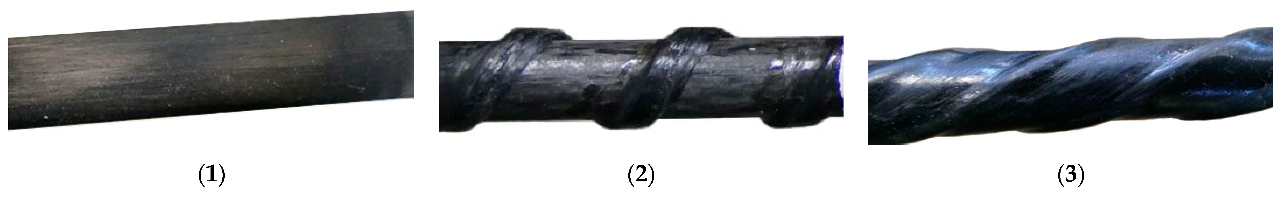
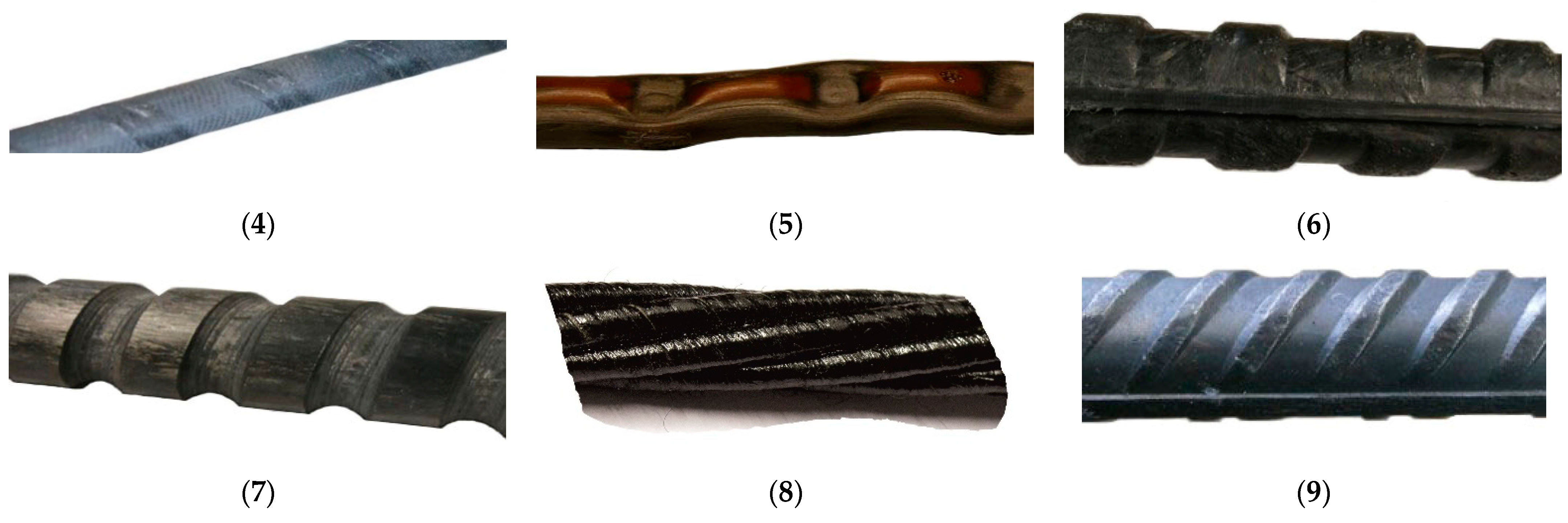
3. Experimental Test Series 1: Various Carbon Rebars

3.1. General

In the first stage, a variety of bond tests were conducted using carbon rebars with different surface profiles and compositions to identify preferred rebars for further bond investigations. In this process, several commercially available carbon rebars from the German market were employed. Additionally, selected carbon rebars developed within the C3 project (Carbon Concrete Composite [14]) were examined for their composite properties. To achieve a comparison to the bond behavior of steel-reinforced concrete, a bond series was also conducted with a conventional steel rebar and the same concrete.

3.2. Materials

For all pull-out tests in Series 1, a specially developed high-strength and self-compacting concrete (HC 1) intended for new components made from carbon-reinforced concrete was used, featuring an aggregate size of 5 mm. The composition of the concrete is listed in Table 1. According to [24,25], the high-strength concrete exhibits mean strengths of 110–140 N/mm2 after 28 days, depending on the chosen curing conditions, as determined on concrete prisms with dimensions of 40 × 40 × 160 mm3. Within this study, the concrete matrix was defined as the reference mixture.
For the reinforcement, eight different rebars and one conventional steel rebar were used, which were available in Germany or in the German research field.
Figure 2 shows the rebars used in the bond tests.
An overview of the various rebar variants, including the necessary details of the diameter and the bond length, is provided in Table 2.
In the following section, each rebar configuration is briefly described, with a primary focus on their respective surface profiles. To characterize the different rebar variants, all rebars were measured prior to testing. Based on these measurements, a reference diameter was defined for each rod configuration. To standardize and establish practical relevance, the measured diameters were rounded to the nearest whole number. Consequently, for some rebar configurations, geometric parameters differing from the manufacturer’s specifications were employed as the basis for the experimental trials. In addition to the geometric data, available information about the rod materials is also presented. For certain rebar configurations, manufacturers of the carbon rebars were unable to provide supplementary information.
Rebar 1 (Figure 2) is a commercially available carbon rebar from a German manufacturer with a smooth surface and an 8 mm diameter.
Rebar 2 (Figure 2) was developed by the Institute of Lightweight Engineering and Polymer Technology (ILK) at TU Dresden within the C3-B1 project [26]. The smooth, pre-hardened 8 mm initial carbon rebar was subsequently loosely wound with a fiber strand. A thermoplastic (PA 6) was used as the matrix for both the rebar and the winding.
Rebar 3 (Figure 2), also developed by ILK within the same project as Rebar 2, features a thermoplastic matrix as well. In this configuration, the fibers were twisted during the manufacturing process, resulting in a helical surface profile [26]. Similar to prestressing strands, a reference diameter of 9 mm is defined for Rebar 3.
Rebar 4 (Figure 2) is a carbon rebar from an Italian manufacturer with an additionally applied thin surface coating that creates a rough structure. Bars with diameters of 6 mm (Rebar 4a) and 8 mm (Rebar 4b) were examined.
Rebar 5 (Figure 2), also a result of a C3-project [26], was designed for use in components exposed to high temperatures. As a result, it features a thermoplastic matrix with a high glass transition temperature. The profiling was performed directly during the pultrusion process by heating the bars sufficiently and then pressing the ribs using a suitable tool.
Rebar 6 (Figure 2), developed by a German company during the C3-B1 project, consists of carbon fibers and a thermoset matrix (epoxy resin based). The profiling with a short fiber-reinforced resin was pressed in an additional production step, resulting in a surface structure resembling that of concrete steel. Its core diameter is 10 mm.
Rebar 7 (Figure 2), also a product of the same German company using similar source materials as Rebar 6, underwent post-curing milling to achieve its profile in a separate production step. Its outer diameter is 10 mm, with a core diameter of 8 mm.
Rebar 8 (Figure 2) consists of seven individual twisted carbon fiber strands and is commonly used in the construction of prestressed structures [13]. For the composite tests, a reference diameter of 9.3 mm was defined based on the manufacturer’s cross-sectional area specifications.
Rebar 9 (Figure 2) is a conventional reinforcement steel with a 10 mm diameter and a rib area ratio fR of 0.096.

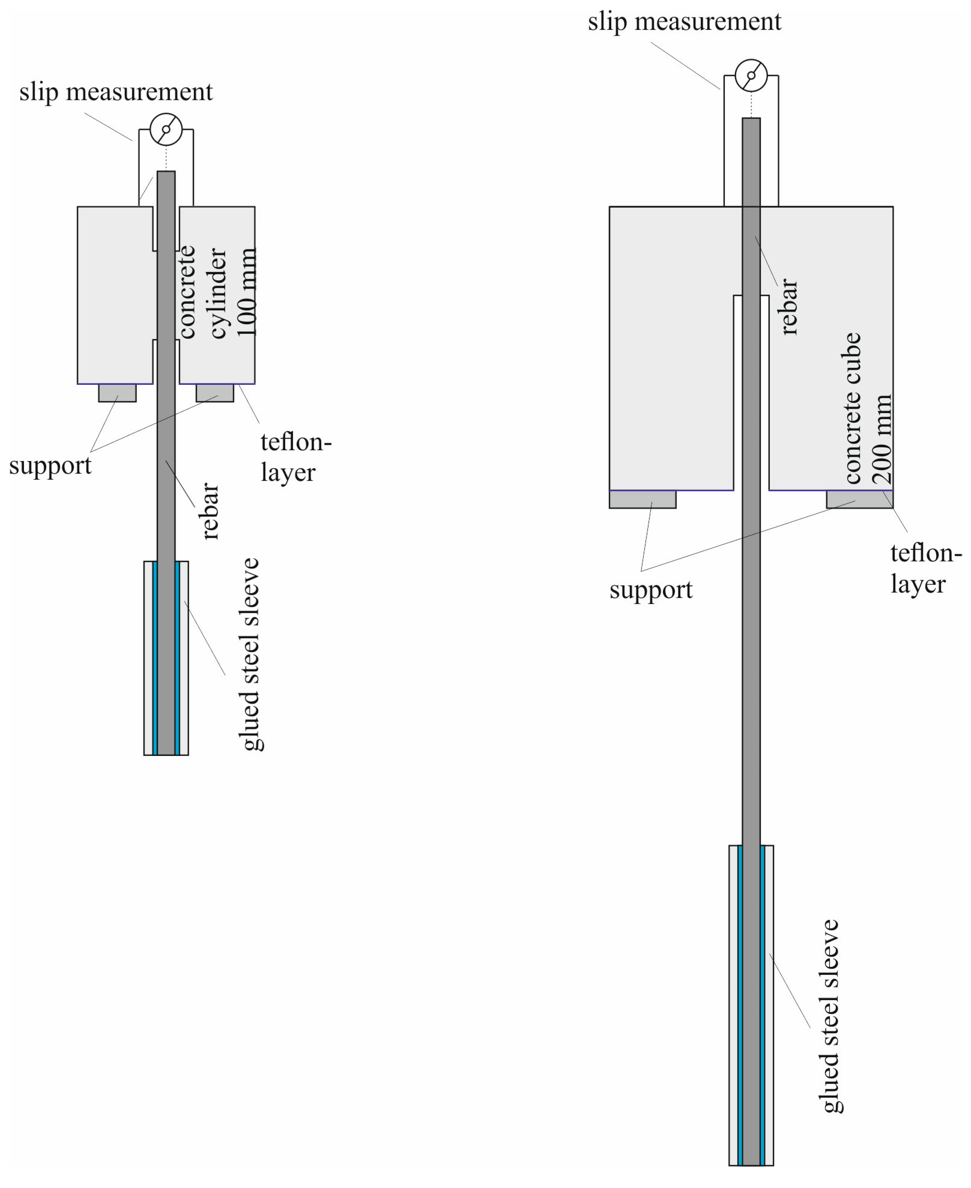
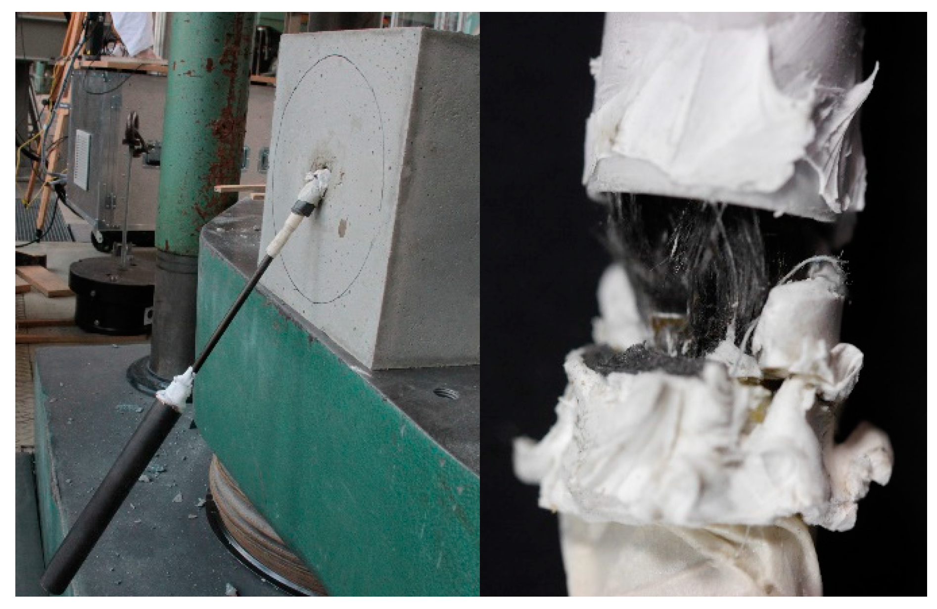
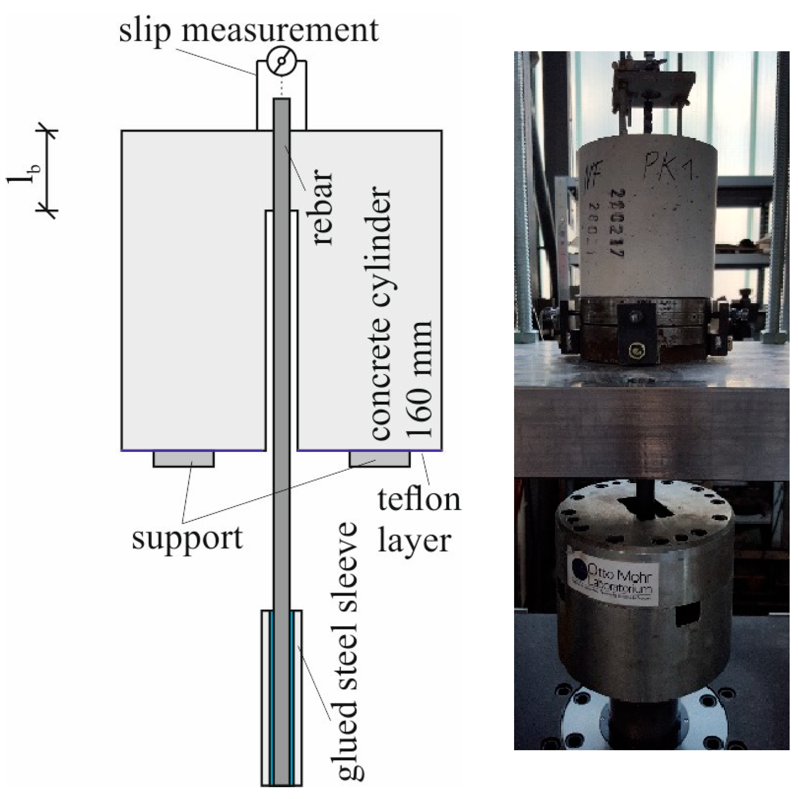
3.3. Sample Preparation, Test Setup, and Execution
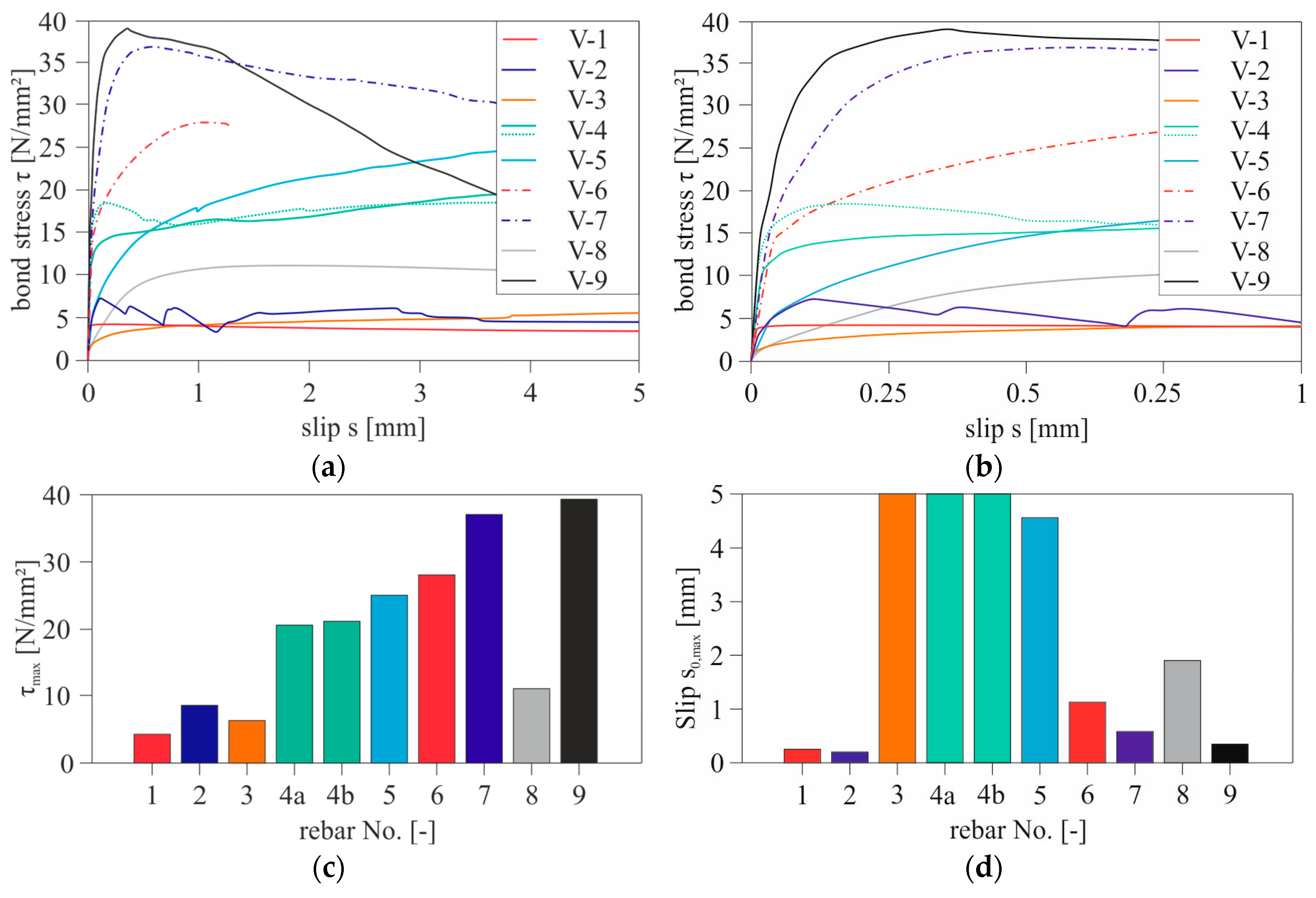
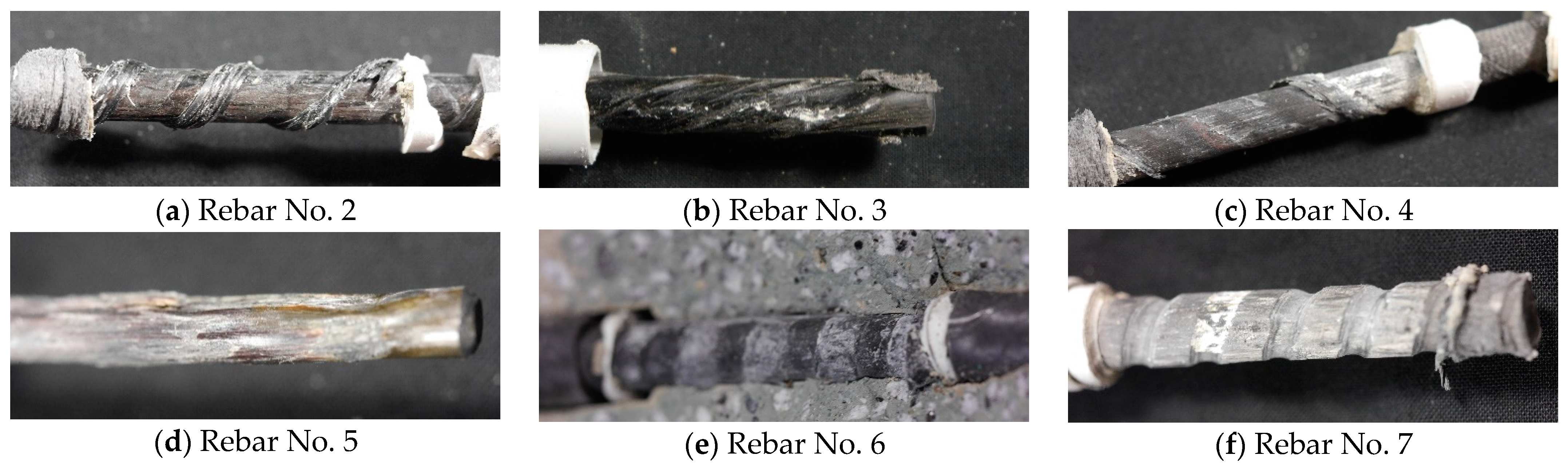
The investigations were conducted at the Otto Mohr Laboratory of TU Dresden. Two different specimen types were employed. Figure 3 (right) illustrates the “Standard” specimen (Specimen 1), which was employed in nearly all experiments. Only during the examination of the bond behavior of Rebar 6 was the smaller Specimen 2, shown in Figure 3 (left), used due to the limited length of the carbon rebar imposed by production constraints. Additionally, due to manufacturing limitations, the bond zone had to be positioned in the middle of Specimen 2, unlike Specimen 1. The bond length was consistently set to 5 bar diameters (dv) for all experiments, following established insights from the literature. However, in the case of the steel bar, it had to be reduced to 2 dv to prevent the steel bar from yielding. To transmit the testing force into the carbon rebar without causing damage, steel sleeves were adhered to the ends of the rebar.
The composite test specimens were prepared in a horizontal orientation. They were left covered in the molds until the third day, then demolded and stored under a sheet at room temperature and 65% relative humidity until the day of testing. Since these were preliminary tests, the composite tests were conducted on average after approximately 12 days. For each test, the slip at the unloaded end of the bar, machine displacement, and test force were measured. The force was applied in a deformation-controlled manner at a testing speed of 0.01 mm/s. A summary of all parameters is provided in Table 2.
For each test series, three concrete prisms with dimensions of 40 × 40 × 160 mm3 were produced in accordance with DIN EN 196-1 [27] and tested on the day of the composite tests to determine flexural and compressive strength. The prisms were used because of the small maximum aggregate size of the concrete. The storage conditions for the prisms deviated from DIN EN 196-1 [27], following the same procedure as the composite test specimens. An overview of the individual composite and concrete tests is presented in Table 2.

3.4. Test Results

The evaluation of the test series for the rebar variants is based on the test force–slip or bond stress–slip relationship (VSB). The following figures depict the mean curves for each rebar configuration. Mean values were computed according to the testing time, as all tests were conducted at the same testing speed. The following observations can be made based on the results: The VSB of the smooth rebar 1 exhibits the typical characteristics of a non-profiled rebar (Figure 4a,b). Similar to smooth concrete steel, the bond force transfer relies on adhesion and friction mechanisms. Thus, the smooth rebar represents the theoretical lower limit of transferable bond stresses for all other surface profiles. Both specimens failed due to rebar pull-out from the concrete.
In the case of Rebar 2, the subsequently applied winding activated an additional shear bond, allowing higher bond stresses to be transferred compared to the smooth Rebar 1. After exceeding the maximum bond stress, τmax, there was a decrease in bond force. The failure and the resulting drop in stress were due to the destruction of the winding fiber strand in the bond zone. Furthermore, in Figure 4a,b, it can be observed that with increasing slip, there is a repeated increase and subsequent decrease in bond stresses, indicative of a zipper-like failure. This is because the destruction of the winding fiber strand occurs gradually in the bond length region. As a result of the additional relative movements between the rebar and the concrete, bond stresses of lower magnitude than τmax can be activated again due to the renewed shear bond. Figure 5 illustrates the destruction of the carbon rebar, particularly the outer winding fiber strand, while the concrete consoles remained undamaged during the test.
For Rebar Configuration 3, the bond resistance was exceeded at a bond stress of approximately 2 N/mm2. Subsequently, shear forces occurred, leading to a continuous but slight increase in bond forces. For this reason, τmax was reached at the maximum measured slip values in the test for this rebar. A notable feature was that the carbon rebar rotated out of the concrete body during the bond test. This phenomenon is similar to the behavior of strand tendons in prestressed concrete, which, when allowed to freely rotate during the bond test, can wind out of the test specimen or, when rotation is impeded, activate additional shear resistance, see [28,29]. If the rotation of the rebar is not hindered by the test setup, lower maximum transferable bond stresses can result, which is why the results of Rebar 3 are only partially applicable to the bond behavior in actual structural elements where such rebar rotations do not occur. In [30], tests on strand tendons found that rotation inhibition leads to higher bond strengths but only in the range of larger slip values. For the relatively small slip values typically encountered in construction, the difference between results with and without rotation inhibition is, therefore, small.
Rebars 4a (dv = 6 mm) and 4b (dv = 8 mm) were characterized by very highly adhesive bonds in the range of 12–17 N/mm2. After exceeding this range, bond stresses could be further increased due to shear action and high frictional bonding. Failure was marked by progressive destruction of the coating, occurring at very large slip values (see Figure 5).
In the first test of Rebar Configuration 5, compared to the smooth Rebar 1, very high bond stresses were achieved, indicating a pronounced shear bond due to the punched profiling. After the test, significant damage to the carbon rebar was observed, as shown in Figure 5d, leading to the pull-out of the carbon rebar from the concrete. However, in the second test of Rebar Configuration 5, premature failure of the specimen occurred. Figure 6 shows the destroyed rebar after the test. The rebar locally failed in the transition zone due to a slight misalignment of the rebar, causing the rebar to suddenly fail during the test. Furthermore, the detail on the right in Figure 6 indicates that the fibers in the bending area were not fully impregnated. Both effects contributed to the failure of the carbon rebar before a bond failure occurred. In summary, it must be noted that the largely manual application of the profiling in the manufacturing process did not achieve uniform profiling quality.
For the experimental determination of the bonding behavior of Rebar Configuration 6, which resembles the form and execution of surface profiling similar to concrete steel, a modified specimen had to be used due to the limited available rebar length, as shown in Figure 3. Due to the limited bond-free length of the carbon rebar, reduced concrete cover in conjunction with high-strength concrete, and high bond forces, the bond body split after exceeding τmax. In addition to the geometric boundary conditions, the splitting tendency is enhanced by the “wedging effect” described in [31,32]. However, for comparison with the other rebar configurations, the test series can still be used, as splitting occurred only on the horizontal or descending branch of the VSB. It should be noted, though, that the increased lateral pressure resulting from the reduced bond-free length could positively affect the transferable bond forces. However, this influence was not further investigated and should be the subject of further studies. Nevertheless, based on the diagrams in Figure 4, it can be observed that the subsequent application of resin ribs has a significant impact on the bonding behavior. Thus, the post-profiling generates bond stresses that are in the range of bond stresses of steel bars, as seen in Figure 4c,d. However, compared to reinforced concrete construction, the failure in Rebar Configuration 6 was characterized by the complete shearing of the resin ribs from the core cross-section, as shown in Figure 5. Similar to Rebar Configuration 6, Variant 7 with milled profiling also achieved maximum bond stresses in the range of a steel bar. Since Specimen Variant 1 was used, there was no splitting of the specimens, but rather, the pull-out of the rebar from the concrete was observed. Besides high absolute values of τmax, Rebar Configuration 6 also exhibits a bond stress–slip relationship similar to a steel bar (see Figure 4). In Rebar 7, in combination with the high-strength concrete, a combined failure was observed, as shown in Figure 5f. The concrete consoles were destroyed in the bond area, and slight to moderate damage to the profiling of the carbon rebar was additionally observed.
Rebar Configuration 8 exhibits bonding behavior that is typical of strand tendons. After overcoming the adhesive bond, similar to Rebar 3 and the bonding behavior of strand tendons, additional shear resistance is activated from the twisting of individual strands. As with Rebar 3, the carbon reinforcement rotated out of the test specimen, resulting in slightly lower maximum bond forces in the test due to the absence of rotation inhibition compared to what would be expected in a structural element.
In the final test series of the preliminary tests (Rebar Configuration 9), a conventional steel rebar with a bond length of 2 ds was tested in a pull-out test, which will serve as a reference.

3.5. Comparison

The experiments aimed to determine a rebar configuration for an in-depth study of the bond behavior of carbon rebars. In Figure 4, it is evident that the steel rebar (Rebar 9) achieved the highest bond stresses and exhibited the greatest bond stiffness. Rebar Configuration 7 was able to transmit maximum bond stresses that are in the range of the steel rebar. It should be noted again that the tests with the steel rebar, in order to prevent its yielding, were conducted with a bond length of 2 ds, as opposed to 5 dv for all carbon rebars, which results in an overestimation of the bond stresses of the steel rebar compared to the carbon rebars. According to [33], for instance, there is a reduction of 15% in converting bond values from 2 ds to 5 ds, so, after conversion, the τmax of Rebar Configurations 7 and 6 are in the range of the steel rebar or even higher. Since, in construction, in addition to maximum bond stresses, bond stiffness, and slip development are of essential importance, Figure 4d also includes the slip values s0;max corresponding to the maximum bond stress τmax. As for some rebar configurations, the maximum bond stresses occurred at slip values greater than 5 mm, but these ranges are of minor significance in construction. The y-axis of the graph is limited to 5 mm. From Figure 4d, it can be concluded that all rebar configurations with suitable interlocking effects on the concrete or no profiling (smooth rebar, Rebar 1) reach their maximum bond stress values at slip values < 1 mm, indicating suitable bond stiffness. In contrast, for the other rebar variants, bond stresses and slip values increase continuously until τmax is reached at very large slip values s0;max. Unlike the rebars with high bond stiffness, rebars with low bond stiffness do not exhibit pronounced interlocking, which results in a gradual failure of these rebars and a final fracture only at large slip values. In [20], by stepwise integration of the experimental data for each rebar configuration, end anchorage lengths and, based on those, mean bond stresses were determined. In summary, Rebar Configuration 7 was selected as the preferred variant for further bond tests.

4. Experimental Test Series 2: Further Investigation

4.1. General

In this chapter, detailed bond investigations are presented using the selected preferred rebar configuration. Specifically, various influencing factors—concrete strength, bond length, and test speed—and their effects on the bond behavior and the type of bond failure are examined in more detail.
In some test series, different batches of the carbon rebar were used. Therefore, whenever different batches are used, it will be highlighted.

4.2. Materials

In the aforementioned series of experiments, Rebar 7 was selected as the preferred variant. This rebar will be further investigated in the following.
As in the previous section, the high-strength self-compacting concrete (HC 1) with a maximum aggregate size of 5 mm serves as the reference concrete. In addition to examining the concrete strength’s influence on the bond behavior, two normal strength concretes, one with very low strength (NC 1) and one with higher strength (NC 2), as well as an ultra-high-performance concrete (UHPC), were used. For each test series, three concrete prisms with dimensions of 40 × 40 × 160 mm3, following DIN EN 196-1 [27], were prepared and tested on the day of the bond tests to determine flexural and compressive strength. The storage conditions for the prisms were different from DIN EN 196-1 [27] but similar to those for the bond specimens. The material properties in Table 3 are the averages of the concrete prisms tested at 28 days.

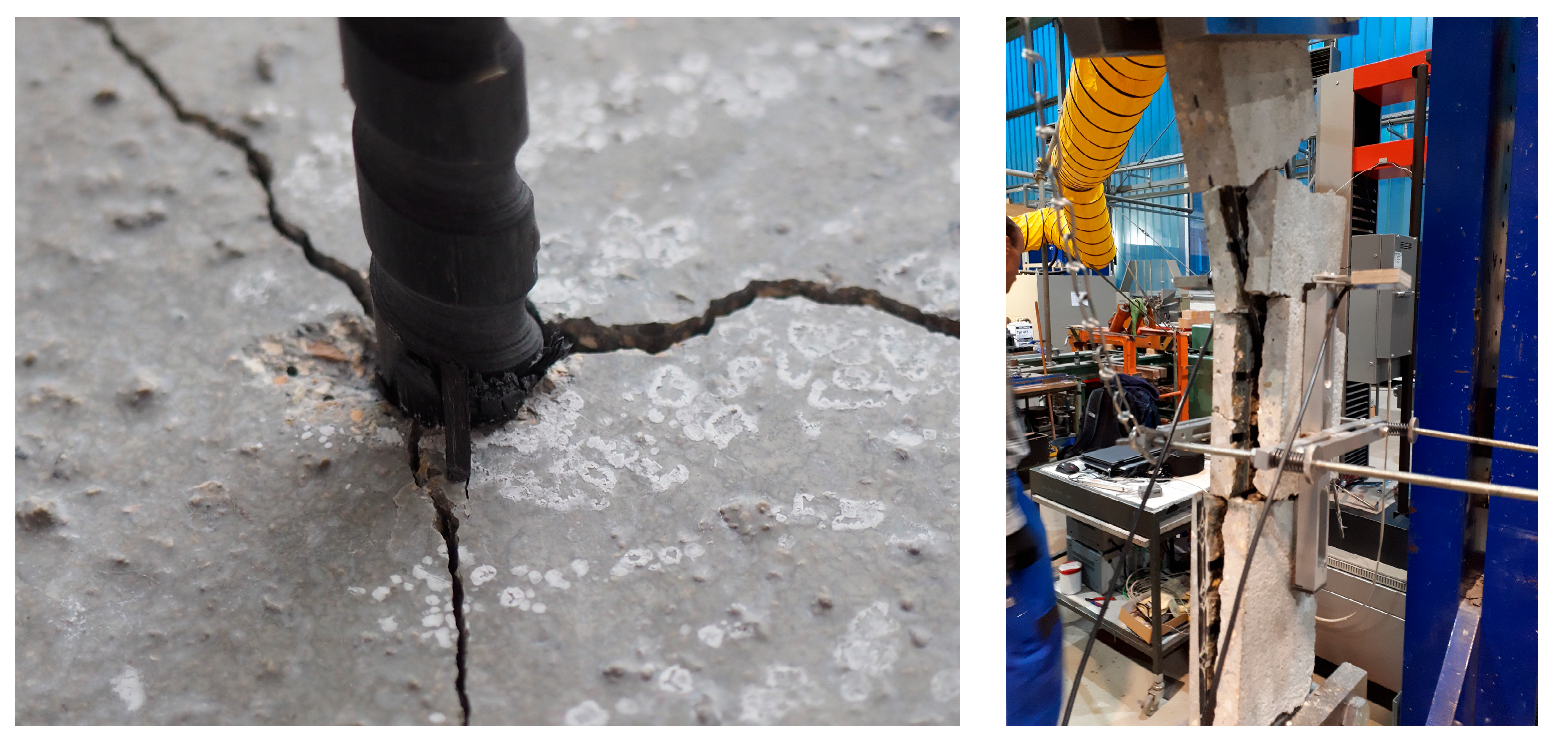
4.3. Sample Preparation, Test Setup, and Execution

The test setup used for characterizing the bond behavior is based on the pull-out test according to RILEM RC 6 [34]. This test setup has been established to investigate various influencing factors on the bond behavior of reinforcement bars in both steel-reinforced concrete construction [16] and previous studies on non-metallic reinforcement bars [11,13]. An advantage is the straightforward production of the test specimens, allowing for the generation of large amounts of data in a short period. The carbon rebar to be tested is embedded in a cylindrical concrete matrix with a diameter and height of 160 mm each over a defined bond length, as shown in Figure 7. The reference value for the bond length is set to five times the effective diameter of the rebar (core diameter) dv. Displacement sensors at the unloaded end of the carbon rebar were used to measure the relative displacement between the top surface of the concrete matrix and the end of the rebar. The load application was deformation-controlled at a test speed of 0.01 mm/s and was implemented using an adhered steel sleeve to avoid damaging the rebar. To investigate the influence of the test speed, additional test speeds of 5 mm/min (0.083 mm/s) and 9 mm/min (0.15 mm/s) were also examined.
While the results are grouped according to bond lengths dependent on the rebar diameter, for example, bond stress at five times the diameter (5 dv) reference length, the actual measured bond lengths (lv) were used to determine the bond stresses to avoid misinterpretation of the results. It is important to note for subsequent investigations that the mean curves of the tests are based on test time rather than slip values. This approach was chosen in line with other research on bond behavior, such as [33], to allow for averaging slip values and corresponding bond stresses at each point in time.
The specimens were produced in an upright position in the Otto Mohr Laboratory at the Technical University of Dresden. After production, the specimens were covered and left in the formwork for 3 days. Subsequently, they were removed from the formwork and stored under a sheet until the testing day at room temperature. The bond tests were typically conducted after 28 days. Four specimens were prepared and tested for each test series to ensure reliable conclusions.

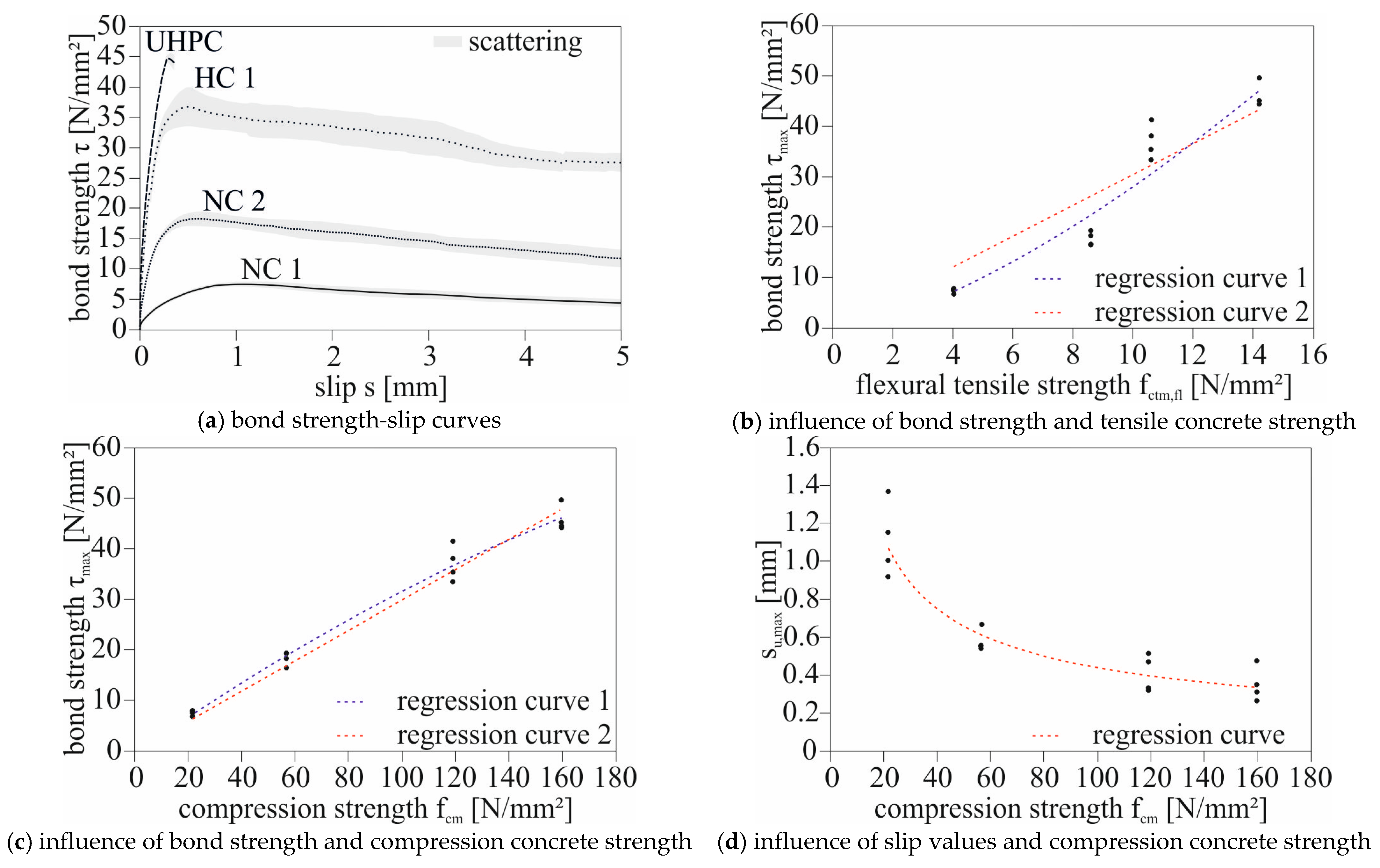
4.4. Experimental Results: Concrete Strength

The preceding descriptions already suggest that bond failure in carbon reinforcements can shift from the concrete side to the reinforcement level. This has been confirmed by various researchers who often observed the initiation of this shift or complete failure of the rebar’s surface profiling starting from a concrete compressive strength of 30 N/mm2 [12,35,36]. Due to this failure mode, there is no further increase in bond stress beyond certain concrete strengths. It should be noted that with higher concrete strength, while higher bond stresses are possible, the risk of splitting increases. Therefore, the first series of experiments aims to evaluate these influencing parameters with the reference rebar (Rebar 7, Figure 2).
From the resulting bond stress–slip relationships in the test series with rebar Batch 1 in Figure 8a, it becomes evident that as the concrete strength increases, both the maximum bond stresses and bond stiffness increase. After the tests were conducted, the test specimens were split to determine the exact failure mechanism. The respective failure images are shown in Figure 9. For the low-strength concrete NC1, the failure could be attributed to the complete failure of the concrete consoles. As the concrete strengths increased, more pronounced scratch marks could be observed on the rebar surface until, in the case of UHPC, the carbon profiling was completely sheared off.
For completeness, it should be mentioned that the test specimens with UHPC split after exceeding the maximum bond stresses, which can be attributed to the high bond stresses and the “wedging effect”. More detailed information on the “wedging effect” can be found in [31,32].
It is known from reinforced concrete tests that the failure plane in pull-out tests with steel bars is always within the concrete, assuming there is no yielding of the bar. Hence, there is a direct dependency of the maximum bond stress on the concrete. Regarding the dependence of maximum bond stresses on concrete compressive or tensile strength, there is not a complete consensus in the literature, although many researchers assume that the dependence on the maximum bond strength results from the concrete tensile strength. In Figure 8b,c, the maximum bond stresses for the rebar are plotted against the determined concrete compressive and tensile strengths. It should be noted that these were determined on mortar prisms with dimensions of 40 × 40 × 160 mm3 and thus cannot be directly applied to the known equations for reinforced concrete without conversion. If an attempt is made to establish a relationship between concrete tensile strength and bond strength similar to reinforced concrete, e.g., using a regression line (Figure 8b), the results cannot be satisfactorily represented. However, when comparing the bond stresses to the average concrete compressive strengths, clear trends can be observed (Figure 8c). Additionally, the experimental results show that as bond stresses increase, the bond stresses relative to concrete compressive strengths slightly decrease with increasing concrete strengths. This can be explained by the shift in failure modes from the shearing of concrete consoles to a combined failure and eventually complete shearing of the surface profiling of the carbon ribs. Therefore, it appears to be more of a quadratic than a linear regression (Figure 8c). Furthermore, Figure 8d demonstrates that as concrete strength increases, there is a reduction in the slip associated with the maximum bond stress. This implies that as concrete strength increases, the bond stiffness for the rebar variant also increases, as indicated by the comparison in Figure 8d.

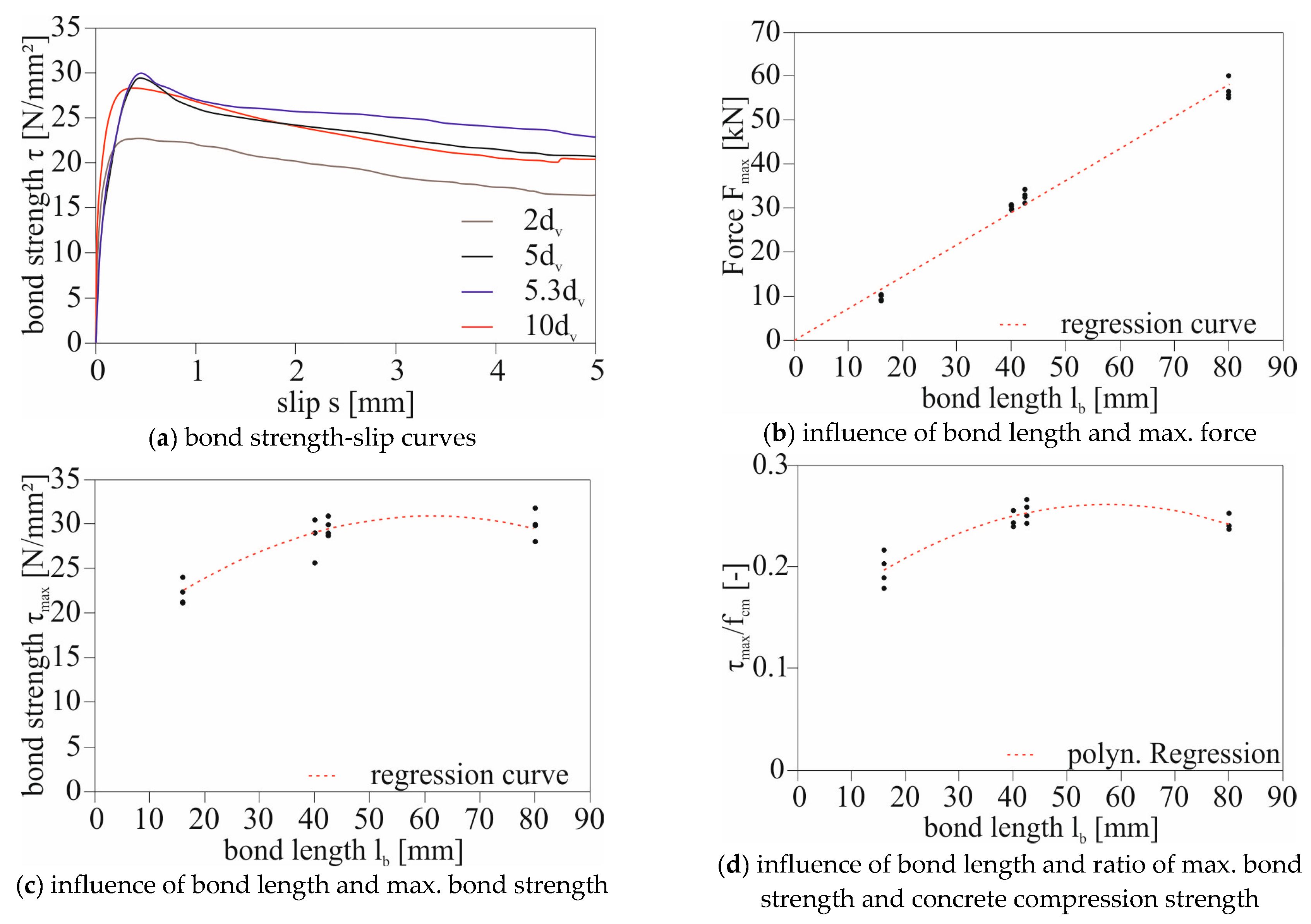
4.5. Experimental Results: Bond Length

In this test series, bond tests were conducted with four different bond lengths. The selected bond lengths were 2 dv, 5 dv, 5.3 dv, and 10 dv. The reference concrete (HC 1) and the reference carbon rebar were used in all experiments. Figure 10 displays the average curves of bond stress–slip relationships for the various bond lengths, the influence of bond length on the testing force (b), the bond strength (c), and the maximum bond stresses related to concrete compressive strengths (d).
As can be seen in Figure 10a, an almost constant level of maximum bond stresses becomes evident at a bond length of 5 dv, which corresponds to a target length of 40 mm. In contrast, the lowest bond stresses were observed at a short bond length of 2 dv. Since all pull-out specimens were manufactured using the same concrete mix and tested after 28 days, the significant variations in bond values at a bond length of 2 dv cannot be attributed to variations in concrete strength as observed in other test series. After the tests were conducted, all specimens were split to determine the exact embedment length of the tests and to gain further insights into the failure mode. As described in the previous section, all specimens exhibited a combined failure mode. Additionally, it was noted that the specimens with a bond length of 2 dv exhibited the most significant damage to the carbon rebar compared to the other bond lengths. Consequently, it can be inferred that with too short embedment lengths, there is a pronounced concentration of forces on individual ribs, and distribution of loads to other ribs, as possible with larger embedment lengths, cannot occur. This assumption can explain the lower bond values at a bond length of 2 dv compared to the other bond lengths. The previously mentioned effect that the average maximum bond stresses are lower at smaller bond lengths is not known in the context of steel-reinforced concrete. In reinforced concrete structures, maximum bond stresses typically decrease with increasing bond length.

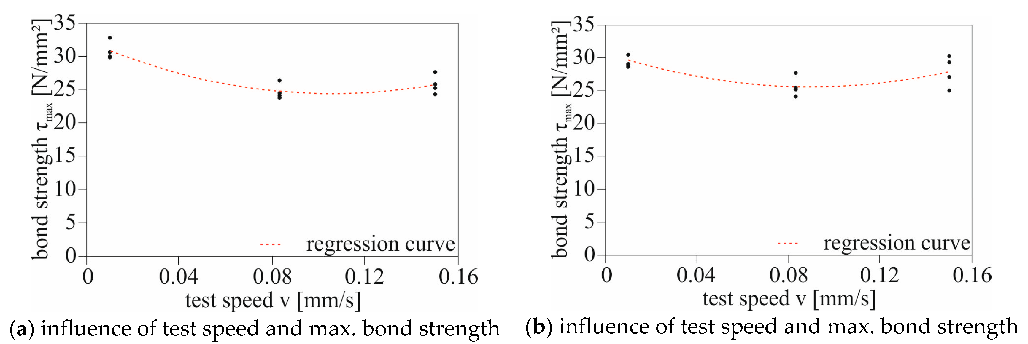
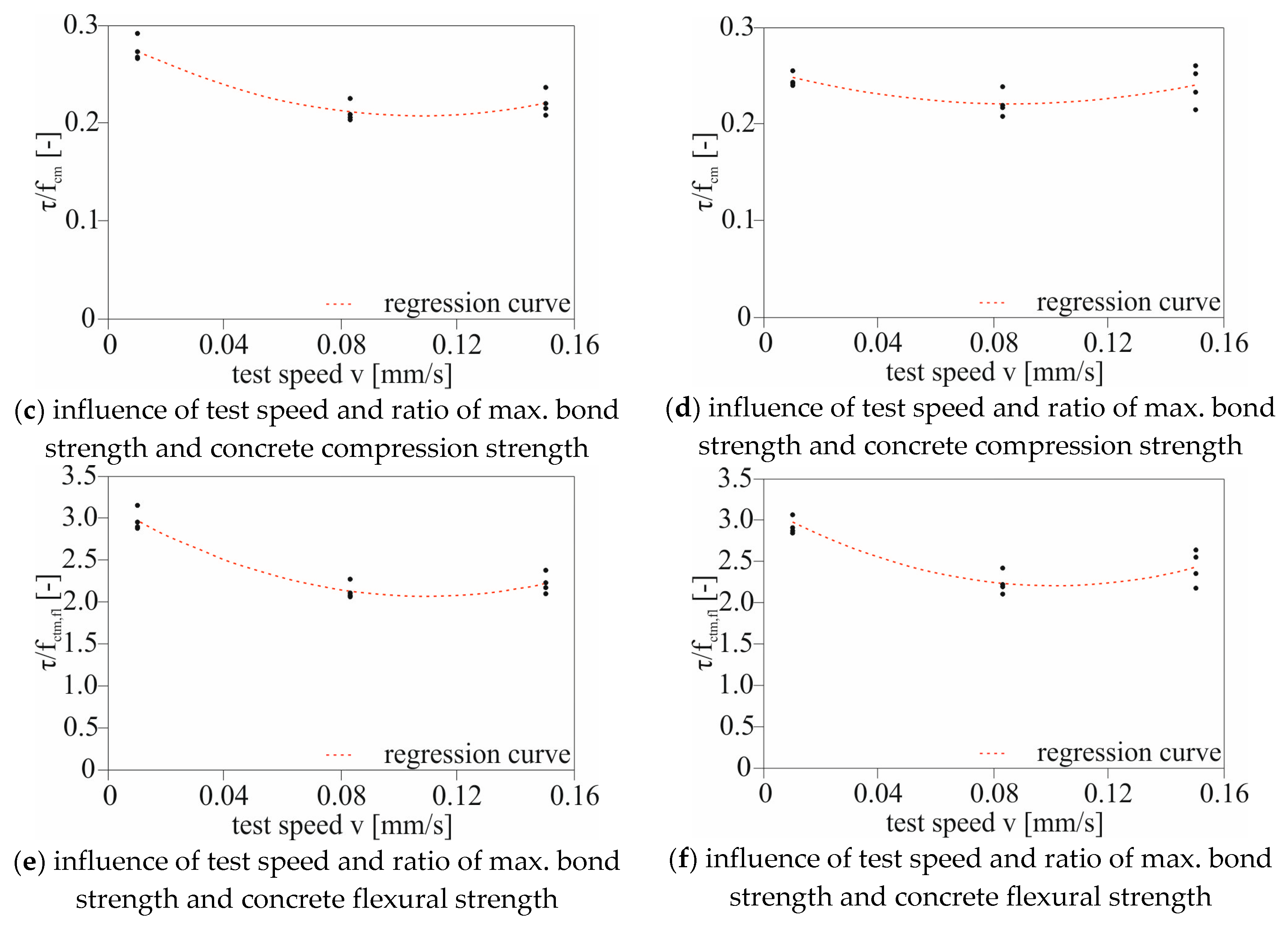
4.6. Experimental Results: Influence of the Test Speed

In addition to the previously mentioned influencing factors, this phase of the study examined whether the test speed has a significant impact on the bond behavior using experimental tests. The test speed in pull-out tests can have a significant influence on the overall load-carrying behavior of the impregnation or resin of the fiber-reinforced composite material. To characterize this influence for the reference rebar in high-strength concrete, pull-out test series were conducted with three different test speeds for two different rebar batches (Batch 2 and Batch 4). The reference pull-out speed, which was used in all previous and subsequent experimental tests in this study, was approximately 0.65 mm/min (0.01 mm/s). With this speed, a test run to reach a slip at the unloaded end of 5 mm takes about 7 min, which provides a reasonable balance between pull-out speed and test time.
To explore the influence of test speed on bond behavior, an additional test series consisting of 4 individual tests for each test speed, namely 5 mm/min (0.083 mm/s) and 9 mm/min (0.15 mm/s), was conducted. Again, the reference concrete (HC 1) was used for all tests, and all other parameters of the various test series remained consistent to ensure result comparability.
Figure 11 presents the results for the second rebar batch on the left and the fourth batch on the right. All specimens exhibited identical pull-out failures (combined failure: shearing of the concrete consoles and partial destruction of the FRP profile). Figure 11a,b, which depict the maximum bond stresses over the pull-out speeds, reveal that the test speed has a significant impact on the maximum bond stresses for the materials used here. This holds true for the carbon rebar, regardless of the batch or the composition of the reference rebar. For the pull-out tests with Batch 2 at a test speed of v = 0.083 mm/s, there was an average reduction in maximum bond stresses (τmax) of approximately 20% compared to v = 0.01 mm/s. For the fourth rebar batch, the reduction in maximum bond stresses for the same test speed was relatively lower at 14%. The difference in bond strengths at varying test speeds cannot be attributed to the variation in concrete strengths, as shown in Figure 11c–f.
From the existing knowledge regarding fiber-reinforced composite (FRC) structures, it is known that the strength of the resin or impregnation increases with increasing test speed. However, this relationship cannot explain why the highest maximum bond stresses in the pull-out test were achieved at the lowest test speed. A conclusion drawn from the experimental tests, including the formulation of a possible hypothesis to describe the influence of test speed on bond strength with a comparison to the literature, will be presented in the next paper.

5. Further Research

This publication aimed to provide a general overview and showcase selected influences. The next publication will describe further influencing factors and present bond tests on pull-out specimens and beam-end tests to investigate bond behavior with realistic concrete coverings. Furthermore, additional analytical considerations and bond models will be established to describe bond behavior in an even more universally applicable manner.
Furthermore, a comparison between the two non-metallic reinforcement materials, rebar, and grid, will be established. The apparent differences between these two reinforcement systems are presented, and it will be analyzed whether differences in the composite behavior can be characterized because of these differences. Today, in addition to carbon rebars, carbon grids are also frequently used in Germany in the field of research as well as for practical applications [37,38,39]. There are already numerous studies on the bond behavior of carbon grids in concrete [40,41,42]. It was also observed that due to the high tensile strengths and suitable bond behavior, the cracking of the concrete often becomes decisive (Figure 12). Thus, analogies to carbon rebars with realistic concrete covers can also be shown (Figure 12). These relationships (including carbon rebars and grids used simultaneously in concrete) must be well known in order to use them together in the construction field.

6. Conclusions

In the paper, a brief overview of the state of the art regarding the bond behavior of FRP (fiber-reinforced polymer) rebars in concrete was provided, which is fundamentally comparable to the bond behavior of steel rebars and concrete. However, due to the material characteristics of FRP bars and the various surface profiling options, there are additional failure and bond mechanisms that must be considered when designing structures with non-metallic bars. In our own experimental bond tests using eight different carbon bars, it was demonstrated that the transferable bond stresses and bond stiffness are significantly controlled by surface profiling. Furthermore, the test results confirmed the findings from the literature that failure modes in non-metallic reinforcement bars vary significantly depending on the surface profiling. Additionally, some bar configurations were found to allow for maximum bond values comparable to those of steel bars. Based on these results, a preferred bar configuration was selected, which will be further elaborated in subsequent publications. Thus, the experiments presented here served to confirm the knowledge from the literature, which was predominantly derived from experimental tests with glass bars, regarding the influence of surface profiling on bond behavior. For a definitive statement on the influence of surface profiling on the bond behavior between carbon bars and concrete, more extensive test series are required.
The investigations into the influencing factors on the bond of the reference carbon bar with milled ribs from the tactile tests showed a bond behavior similar to that of reinforced concrete structures. In this publication, the specific influence of concrete strength on failure mode and maximum bond stresses was considered, as well as the effects of different bond lengths on bond behavior and the influence of test speed on bond strengths. In the course of this work, it was demonstrated that for the selected bar configuration, both concrete strength and bond length have a significant influence on bond behavior. Higher concrete strength leads to higher bond strength and stiffness, which is of essential importance in practical applications. The effect described in the literature of an upper limit of concrete strength beyond which bond stresses no longer increase due to the shearing of the surface profiling of the bar was also observed for the reference carbon bar. For the bar investigated here, this limit was 50 N/mm².
Regarding the influence of bond length on average bond stresses, the established approaches and bond mechanisms for large bond lengths were confirmed. For the reference bar, a decrease in average bond stresses with larger bond lengths was also observed, although the percentage reduction was smaller compared to steel-reinforced concrete. However, the pull-out tests with short bond lengths (lb = 2 dv) revealed the need for further research, as the lowest average bond stresses were measured at these bond lengths. A possible explanation was found by considering the transverse compressive sensitivity of the carbon bar in conjunction with the activated FRP ribs. Nevertheless, further research is required at this point to provide a more precise description of this parameter.
Interestingly, the obtained bond values from experimental pull-out tests with various test speeds exhibited a dependence, suggesting a conclusion for future research and standards. Rather than specifying an upper limit for test speed, it may be more appropriate to determine test speeds precisely. This could lead to improved comparability of experimental results in the future.

Author Contributions

Conceptualization, A.S., M.M. and E.S.; Methodology, A.S. and D.E.; Software, D.E.; Validation, S.M., E.S. and F.S.; Investigation, A.S.; Resources, M.M.; Writing—original draft, A.S., S.M. and M.M.; Writing—review and editing, E.S. and F.S.; Visualization, A.S.; Supervision, A.S.; Project administration, A.S.; Funding acquisition, A.S. and F.S. All authors have read and agreed to the published version of the manuscript.

Funding

This research was funded by Federal Ministry of Education and Research: C3-V1.2.

Data Availability Statement

The data presented in this study are available on request from the corresponding author. The data are not publicly available due to privacy.

Conflicts of Interest

Authors Alexander Schumann, Sebastian May, Maximilian May and Elisabeth Schütze were employed by the company CARBOCON GMBH. The remaining authors declare that the research was conducted in the absence of any commercial or financial relationships that could be construed as a potential conflict of interest.

References

  1. Wagner, J.; Wurgau, C.; Schumann, A.; Schutze, E.; Ehlig, D.; Nietner, L.; Curbach, M. Strengthening of Reinforced Concrete Structures with Carbon Reinforced Concrete—Possibilities and Challenges. Civ. Eng. 2022, 3, 400–426. [Google Scholar] [CrossRef]
  2. May, M.; Schumann, A.; May, S. The new approval for the sustainable strengthening of existing structures with carbon reinforced concrete. Civ. Eng. Des. 2022, 4, 72–78. [Google Scholar] [CrossRef]
  3. Riegelmann, P.; Schumann, A.; May, S.; Bochmann, J.; Garibaldi, M.P.; Curbach, M. Müther’s shell structures in Germany—A solution to avoid demolition. Proc. Inst. Civ. Eng. Eng. Hist. Herit. 2021, 174, 124–132. [Google Scholar] [CrossRef]
  4. Backes, J.G.; Schmidt, L.; Bielak, J.; Rosario, P.; Traverso, M.; Claben, M. Comparative Cradle-to-Grave Carbon Footprint of a CFRP-Grid Reinforced Concrete Façade Panel. Sustainability 2023, 15, 11548. [Google Scholar] [CrossRef]
  5. Reichenbach, S.; Preinstorfer, P.; Hammerl, M.; Kromoser, B. A review on embedded fibre-reinforced polymer reinforcement in structural concrete in Europe. Constr. Build. Mater. 2021, 307, 124946. [Google Scholar] [CrossRef]
  6. Bielak, J.; Schmidt, M.; Hegger, J.; Fesse, F. Structural Behavior of Large-Scale I-Beams with Combined Textile and CFRP Reinforcement. Appl. Sci. 2020, 10, 4625. [Google Scholar] [CrossRef]
  7. Schumann, A.; May, S.; Curbach, M. Design and Testing of various Ceiling Elements made of Carbon Reinforced Concrete. Proceedings 2018, 2, 543. [Google Scholar] [CrossRef]
  8. Apitz, A.; Schimtz, J.; Huckler, A.; Schlaich, M. New thermoplastic carbon fiber reinforced polymer rebars and stirrups. Struct. Concr. 2022, 23, 923–938. [Google Scholar] [CrossRef]
  9. Schumann, A.; May, M.; Curbach, M. Carbonstäbe im Bauwesen—Teil 1: Grundlegende Materialcharakteristiken. Beton Stahlbetonbau 2018, 113, 868–876. [Google Scholar] [CrossRef]
  10. Hammerl, M.; Kromoser, B. Bending Behaviour of Prestressed T-Shaped Concrete Beams Reinforced with FRP—Experimental and Analytical Investigations. Materials 2022, 15, 3843. [Google Scholar] [CrossRef]
  11. Hammerl, M.; Stoiber, N.; Haemmerle, J.; Shams, A.; Bischoff, T.; Kromoser, B. Verbundverhalten umwickelter CFK-Stäbe in Beton—Kurzzeituntersuchung der Verbundeigenschaften mittels Pull-out-Tests. Beton Stahlbetonbau 2021, 116, 935–946. [Google Scholar] [CrossRef]
  12. Pritschow, A. Zum Verbundverhalten von CFK-Betonbauteilen mit Faserverbundkunststoff-Bewehrung. Ph.D. Thesis, University of Stuttgart, Stuttgart, Germany, 2016. [Google Scholar]
  13. Stark, A.P.B.; Claßen, M.; Hegger, J. Bond behaviour of CFRP tendons in UHPFRC. Eng. Struct. 2019, 178, 148–161. [Google Scholar] [CrossRef]
  14. Lieboldt, M.; Tietze, M.; Schladitz, F. C³-Projekt—Erfolgreiche Partnerschaft für Innovation im Bauwesen. Bauingenieur 2018, 98, 265–273. [Google Scholar] [CrossRef]
  15. Máca, P.; Panteki, E.; Combe, U.; Curbach, M. Definition of Loading Rate for the Experimental and Numerical Investigation of Reinforcement’s Bond in Concrete Under Impact Loading. In High Tech Concrete: Where Technology and Engineering Meet; Springer: Cham, Switzerland, 2017; pp. 929–937. [Google Scholar] [CrossRef]
  16. Gambarova, P.G.; Rosati, G.P. Bond and splitting in reinforced concrete: Test results on bar pull-out. Mater. Struct. 1996, 29, 267–276. [Google Scholar] [CrossRef]
  17. Zobel, R.; Curbach, M. Numerical study of reinforced and prestressed concrete components under biaxial tensile stresses. Struct. Concr. 2017, 18, 356–365. [Google Scholar] [CrossRef]
  18. Betz, P.; Schumann, A.; Scheerer, S.; Curbach, M. Carbonstäbe im Bauwesen—Teil 5: Einflussfaktoren auf das Verbundverhalten. Beton Stahlbetonbau 2021, 116, 924–934. [Google Scholar] [CrossRef]
  19. Suppanz, F.; Kromoser, B. Verbundverhalten subtraktiv bearbeiteter CFK-Stäbe in UHPC. Beton Stahlbetonbau 2020, 115, 504–513. [Google Scholar] [CrossRef]
  20. Schumann, A. Experimentelle Untersuchungen des Verbundverhaltens von Carbonstäben in Betonmatrices. Ph.D. Thesis, University of Dresden, Dresden, Germany, 2020. [Google Scholar]
  21. Schumann, A.; May, M.; Scheerer, S.; Curbach, M. Carbonstäbe im Bauwesen—Teil 2: Verbundverhalten—Verbundversuche an unterschiedlichen Carbonstäben. Beton Stahlbetonbau 2020, 115, 962–971. [Google Scholar] [CrossRef]
  22. Schumann, A.; Schladitz, F.; Curbach, M. Bond behavior of carbon rebars. Carbon 2020, 6, 9. [Google Scholar]
  23. Accornero, F.; Cafarelli, R.; Carpinteri, A.; Nanni, A. Scale effects in GFRP-bar reinforced concrete beams. Struct. Concr. 2023, 24, 2817–2826. [Google Scholar] [CrossRef]
  24. Schneider, K. Basisvorhaben B2: Nachhaltige Bindemittel und Betone für die Zukunft: Matrix Datenblatt: C3-B2-NF-3–139–8. Ergebnisplattform im C3-Vorhaben “Carbon Concrete Composite”. 2016. Available online: https://portal.bauen-neu-denken.de (accessed on 15 December 2018).
  25. Schneider, K.; Butler, M.; Mechtcherine, V. Carbon Concrete Composite C3—Nachhaltige Bindemittel und Betone für die Zukunft. Beton Stahlbetonbau 2017, 112, 784–794. [Google Scholar] [CrossRef]
  26. Böhm, R.; Thieme, M.; Wohlfahrt, D.; Wolz, D.S.; Richter, B.; Jager, H. Reinforcement Systems for Carbon Concrete Composites Based on Low-Cost Carbon Fibers. Fibers 2018, 6, 56. [Google Scholar] [CrossRef]
  27. DIN EN 196–1; Methods of Testing Cement–Part 1: Determination of Strength. European Commission: Brussels, Belgium, 2016.
  28. Will, N. Zum Verbundverhalten von Spanngliedern mit Nachträglichem Verbund unter Statischer und Dynamischer Dauerbeanspruchung. Ph.D. Thesis, University of Aachen, Aachen, Germany, 1997. [Google Scholar]
  29. Ullner, R. Verbundverhalten von Litzenspanngliedern mit Nachträglichem Verbund. Ph.D. Thesis, University of Zürich, Zürich, Switzerland, 2008. [Google Scholar]
  30. Nitsch, A. Spannbetonfertigteile mit Teilweiser Vorspannung aus Hochfestem Beton. Ph.D. Thesis, University of Aachen, Aachen, Germany, 2001. [Google Scholar]
  31. Achillides, Z. Bond Behaviour of FRP Bars in Concrete. Ph.D. Thesis, University of Sheffield, Sheffield, UK, 1998. [Google Scholar]
  32. Achillides, Z.; Pilakoutas, K. Bond Behavior of Fiber Reinforced Polymer Bars under Direct Pullout Conditions. J. Compos. Constr. 2004, 8, 173–181. [Google Scholar] [CrossRef]
  33. Lindorf, A.; Lemnitzer, L.; Curbach, M. Experimental investigations on bond behaviour of reinforced concrete under transverse tension and repeated loading. Eng. Struct. 2009, 31, 1469–1476. [Google Scholar] [CrossRef]
  34. RILEM. Essais portant sur l’adhérence des armatures du béton: 2. Essai par traction—Bond test for reinforcing steel: 2. Pull-Out Test. Matériaux Constr. 1970, 3, 175–178. [Google Scholar] [CrossRef]
  35. Rolland, A.; Quiertant, M.; Khadour, A.; Chataigner, S.; Benzarti, K.; Argoul, P. Experimental investigations on the bond behavior between concrete and FRP reinforcing bars. Constr. Build. Mater. 2018, 173, 136–148. [Google Scholar] [CrossRef]
  36. Zhou, Z.; Qiao, P. Bond behavior of epoxy-coated rebar in ultra-high performance concrete. Constr. Build. Mater. 2018, 182, 406–417. [Google Scholar] [CrossRef]
  37. Manfred, C.; Sebastian, M.; Müller, E.; Schumann, A.; Schütze, E.; Wagner, J. Verstärken mit Carbonbeton. In Betonkalender 2022: Nachhaltigkeit, Digitalisierung, Instandhaltung, 111, Jahrgang; Ernst & Sohn GmbH & Co. KG.: Berlin, Germany, 2022; Chapter 12. [Google Scholar] [CrossRef]
  38. Polskoy, P.P.; Mailyan, D.; Beskopylny, A.N.; Meskhi, B. Bearing Capacity of Reinforced Concrete Beams with Initial Cracks Reinforced with Polymer Composite Materials. Polymers 2022, 14, 3337. [Google Scholar] [CrossRef] [PubMed]
  39. Schumann, A.; Schöffel, J.; May, S.; Schladitz, F. Ressourceneinsparung mit Carbonbeton Am Beispiel der Verstärkung der Hyparschale in Magdeburg. In Nachhaltigkeit, Ressourceneffizienz und Klimaschutz Konstruktive Lösungen für das Planen und Bauen—Aktueller Stand der Technik; Hauke, B., Ed.; Institut Bauen und Umwelt: Berlin, Germany, 2021. [Google Scholar]
  40. Schütze, E.; Bielak, J.; Scheerer, S.; Hegger, J.; Curbach, M. Uniaxial tensile test for carbon reinforced concrete with textile reinforcement. Beton Stahlbetonbau 2018, 11, 33–47. [Google Scholar] [CrossRef]
  41. Frenzel, M.; Baumgartel, E.; Marx, S.; Curbach, M. The Cracking and Tensile-Load-Bearing Behaviour of Concrete Reinforced with Sanded Carbon Grids. Buildings 2023, 13, 2652. [Google Scholar] [CrossRef]
  42. Preinstorfer, P.; Yanik, S.; Kirnbaur, J.; Lees, J.M.; Robisson, A. Cracking behaviour of textile-reinforced concrete with varying concrete cover and textile surface finish. Compos. Struct. 2023, 312, 116859. [Google Scholar] [CrossRef]
Figure 1. Carbon rebar with destroyed lugs of the rebar (photo: A. Schumann).
Buildings 13 02932 g001
Figure 2. Used carbon rebars (18) and steel rebar (9) (photo: A. Schumann).
Buildings 13 02932 g002aBuildings 13 02932 g002b
Figure 3. Used test setups and specimens; left: No. 1; right: No. 2 (photo: A. Schumann).
Buildings 13 02932 g003
Figure 4. Test results: (a) mean bond stress–slip relationships (VSB) of the examined rebars (S); (b) enlarged detail of the VSB at low slip values; (c) comparison of the maximum bond stresses; (d) comparison of the slip values associated with τmax; in the diagrams, only valid failure modes were considered (photo: A. Schumann).
Buildings 13 02932 g004
Figure 5. Surfaces of the carbon rebars after the bond tests (photo: A. Schumann).
Buildings 13 02932 g005
Figure 6. Failed carbon rebar 5 (photo: A. Schumann).
Buildings 13 02932 g006
Figure 7. Experimental test setup (photo: A. Schumann).
Buildings 13 02932 g007
Figure 8. Influence of the concrete strength on the bond stress of Batch 1 (photo: A. Schumann).
Buildings 13 02932 g008
Figure 9. Influence of the concrete strength on the failure mode. Left: failure of the concrete consoles; right: failure of the carbon ribs (photo: A. Schumann).
Buildings 13 02932 g009
Figure 10. Influence of the bond length on the bond stress (photo: A. Schumann).
Buildings 13 02932 g010
Figure 11. Influence of the test speed; left: Batch 2; right: Batch 4 (photo: A. Schumann).
Buildings 13 02932 g011aBuildings 13 02932 g011b
Figure 12. Splitting forces of carbon reinforcements; left: rebar; right: carbon grid (photo: S. May).
Buildings 13 02932 g012
Table 1. Components of the used concrete.
BinderQuartz Fine SandSand 0/2Aggregate 2/5SuperplasticizerWater
(kg/m³)(kg/m³)(kg/m³)(kg/m³)(kg/m³)(kg/m³)
62125053083716145
Table 2. Test parameters of the bond tests.
Name
(-)
Rebar
(-)
Specimen No. (-)lb
(mm)
dv
(mm)
Age
(d)
τmax
(N/mm2)
so,max
(mm)
fcm
(N/mm2)
fctm,fl
(N/mm2)
V-1-111408104.30.2107.310.4
V-1-211408104.30.3107.310.4
V-2-121408148.10.2108.211.2
V-2-221408146.90.2108.211.2
V-2-3214081410.70.3108.211.2
V-3-131459116.010.9108.710.0
V-3-231459117.410.8108.710.0
V-3-331459115.85.7108.79.98
V-4-1413061220.05.7112.49.8
V-4-2413061221.54.2112.49.8
V-4-3413061219.910.2112.49.8
V-4-4414081221.26.1112.49.8
V-4-5414081221.15.3112.49.8
V-4-6414081221.26.7112.49.8
V-5-1513061121.56.5108.710.0
V-5-2513061128.92.6108.710.0
V-6-16250101229.11.1112.49.8
V-6-26250101226.751.4112.49.8
V-6-36250101228.90.9112.49.8
V-7-17a14081336.00.5115.010.1
V-7-27a14081338.050.6115.010.1
V-8-18146.59.31211.72.3111.59.9
V-8-28146.59.31211.01.7111.59.9
V-8-38146.59.31211.21.8111.59.9
V-9-19120101138.00.3108.710.0
V-9-29120101140.10.4108.710.0
V-9-39120101140.00.3108.710.0
Table 3. Test results (mean values) of the used concrete mixtures.
Name Compressive StrengthFlexural Tensile Strength
(-)(N/mm2)(N/mm2)
NC120.74.0
NC256.88.6
HC1119.110.6
UHPC159.714.2
Disclaimer/Publisher’s Note: The statements, opinions and data contained in all publications are solely those of the individual author(s) and contributor(s) and not of MDPI and/or the editor(s). MDPI and/or the editor(s) disclaim responsibility for any injury to people or property resulting from any ideas, methods, instructions or products referred to in the content.

