
Digital Prefabrication of Lightweight Building Elements for Circular Economy: Material-Minimised Ribbed Floor Slabs Made of Extruded Carbon Reinforced Concrete (ExCRC)

 , , , ,
Abstract
:1. Introduction
2. Materials and Methods
2.1. Design of Ribbed Slabs Made of ExCRC
2.2. Materials
3. Laboratory-Scale Implementation of a One-Way ExCRC Slab
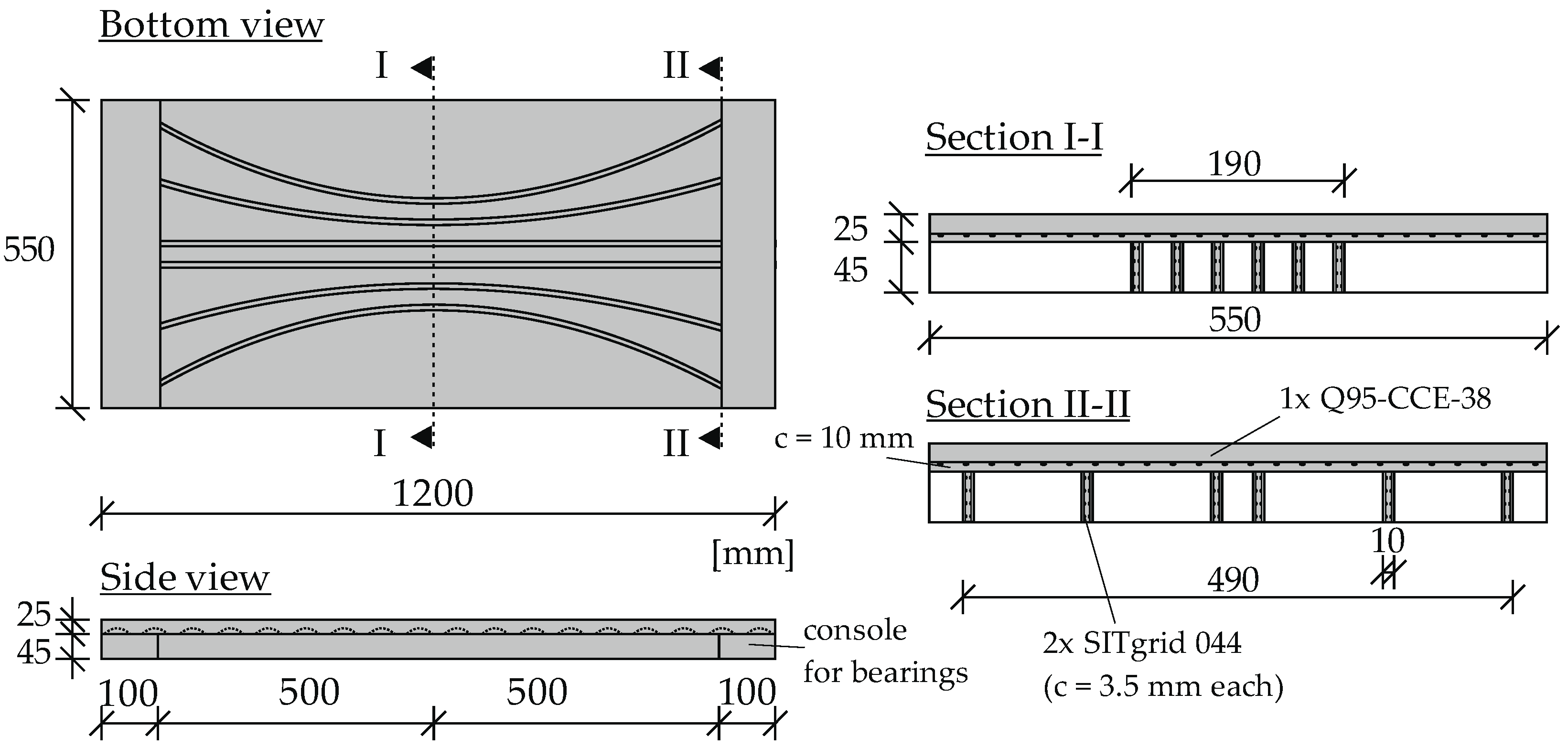
3.1. Design Selection
3.2. Production of the Concrete
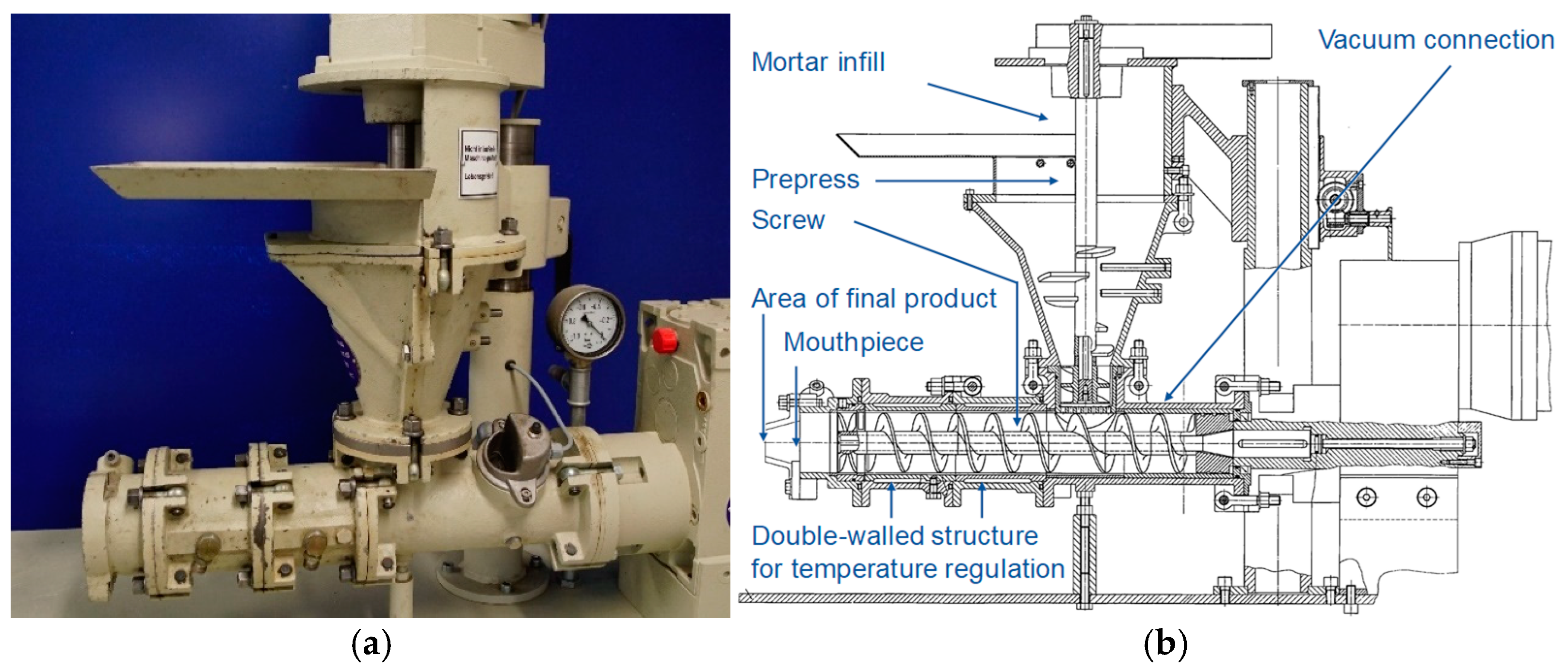
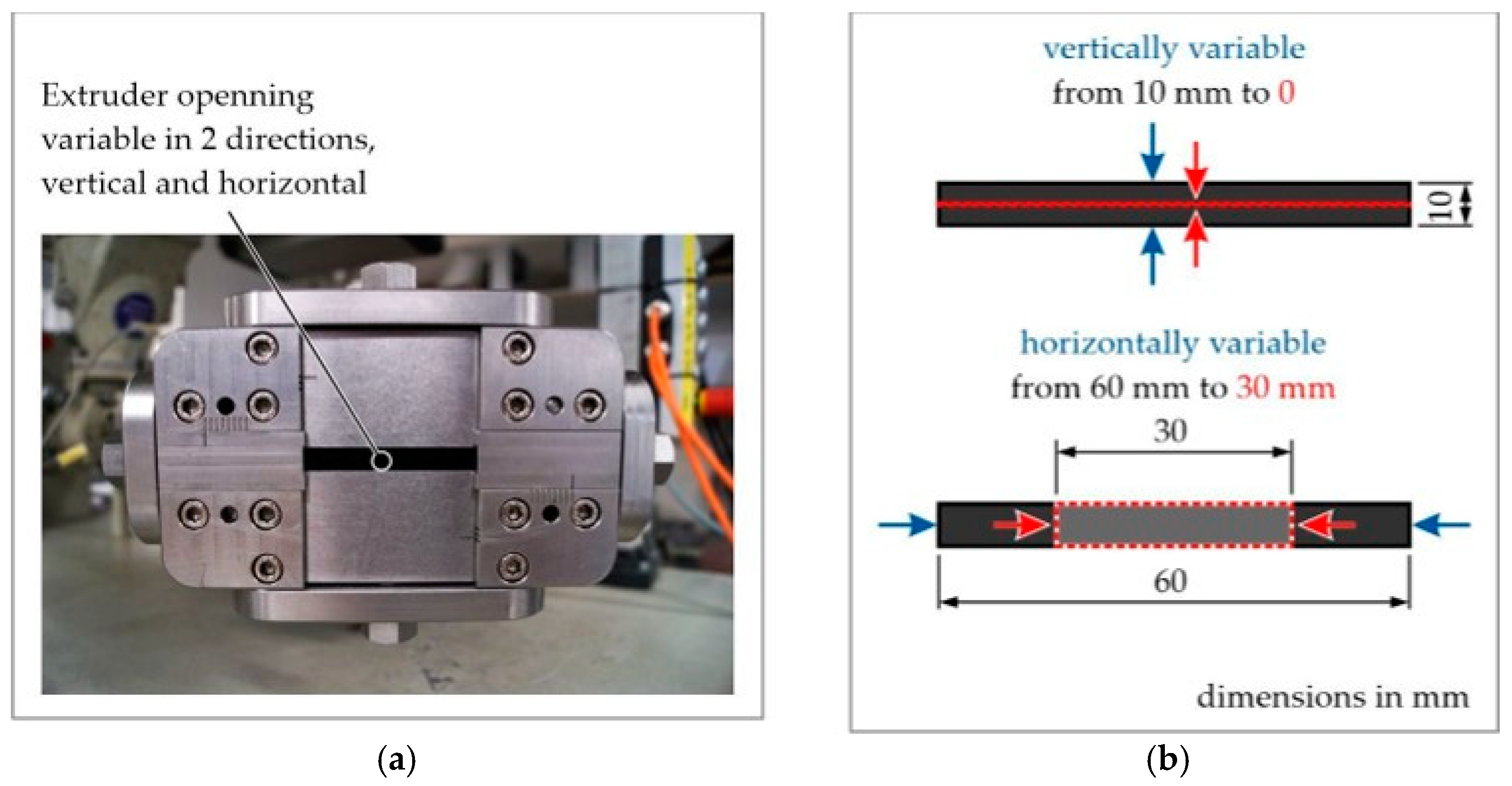
3.3. Concrete Extrusion Process
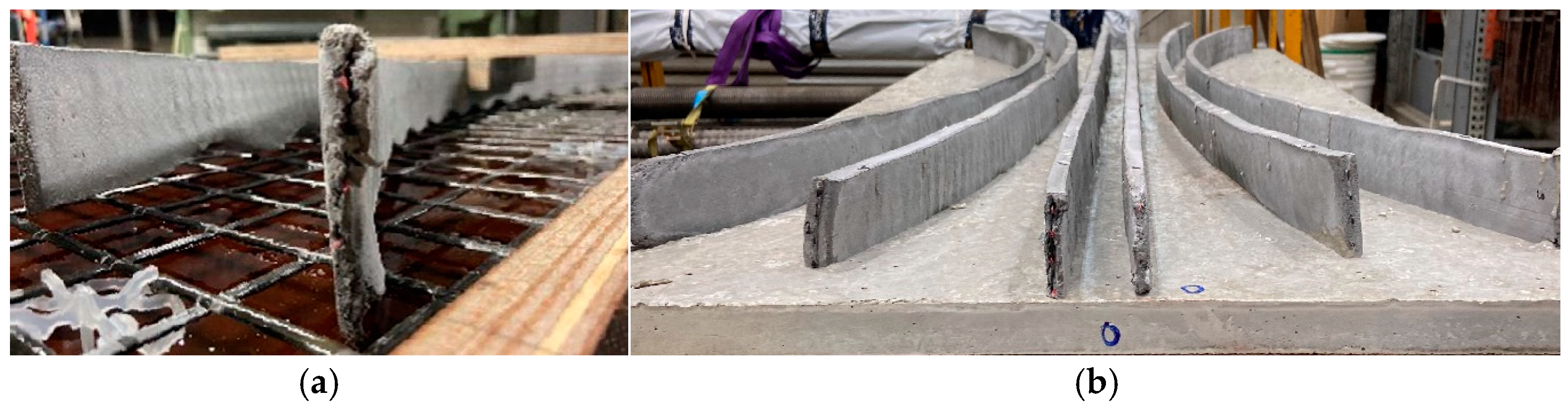
3.4. Assembly of the Demonstrator
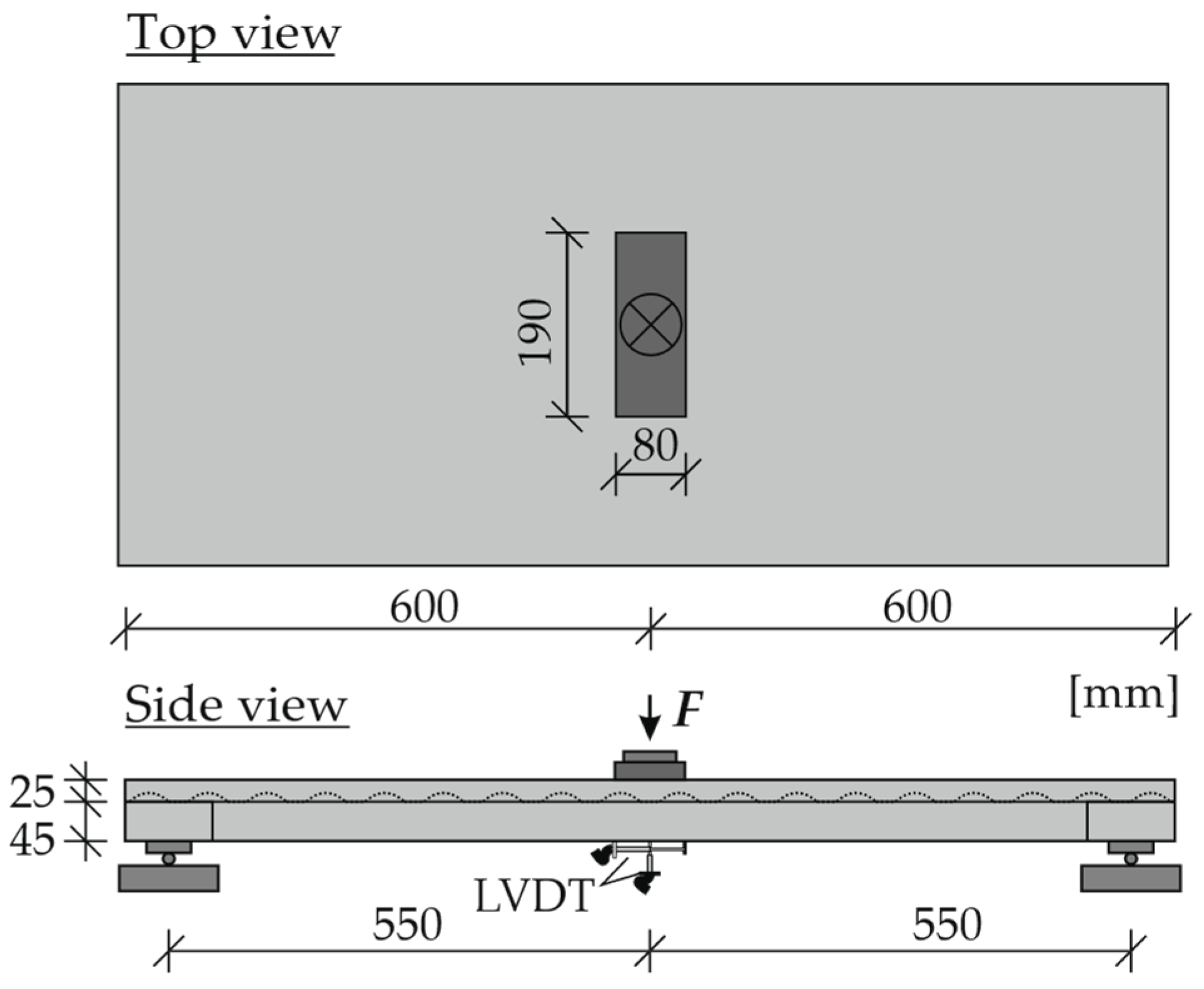
3.5. Testing of the Demonstrator
4. Results and Discussion
4.1. Test Results
4.2. Upscaling for Real-Scale Applications
5. Conclusions
- For the first time, an innovative ribbed slab with load-adjusted webs was designed and implemented using extruded variably shaped CRC strips with two layers of textile CFRP grids and a conventionally cast CRC top slab.
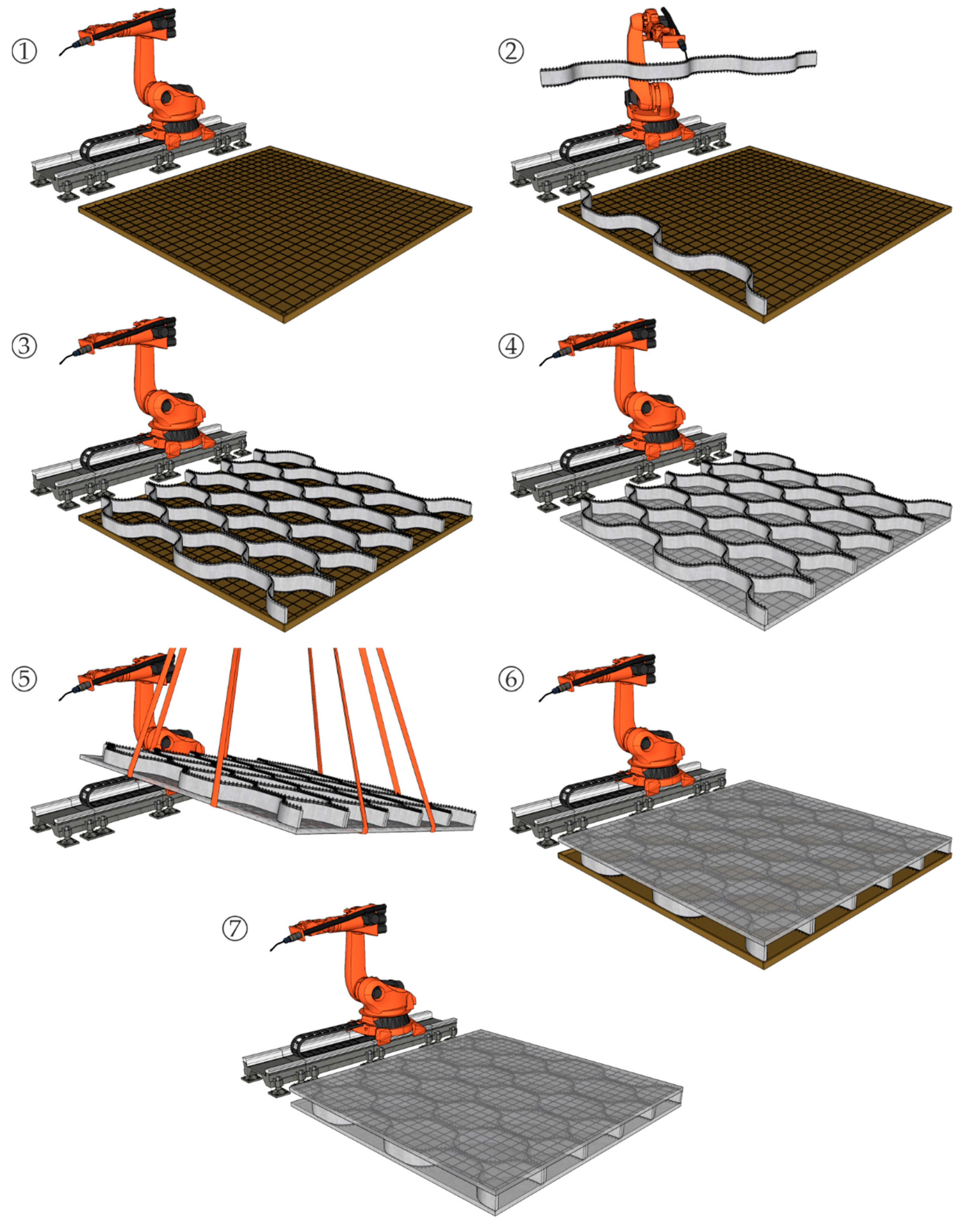
- The method developed here allows the production of ExCRC web components with a variable cross-section that can be automatically incorporated into ribbed slabs. The easy and formwork-free production allows very economic realisation compared with conventionally cast ribbed slabs.
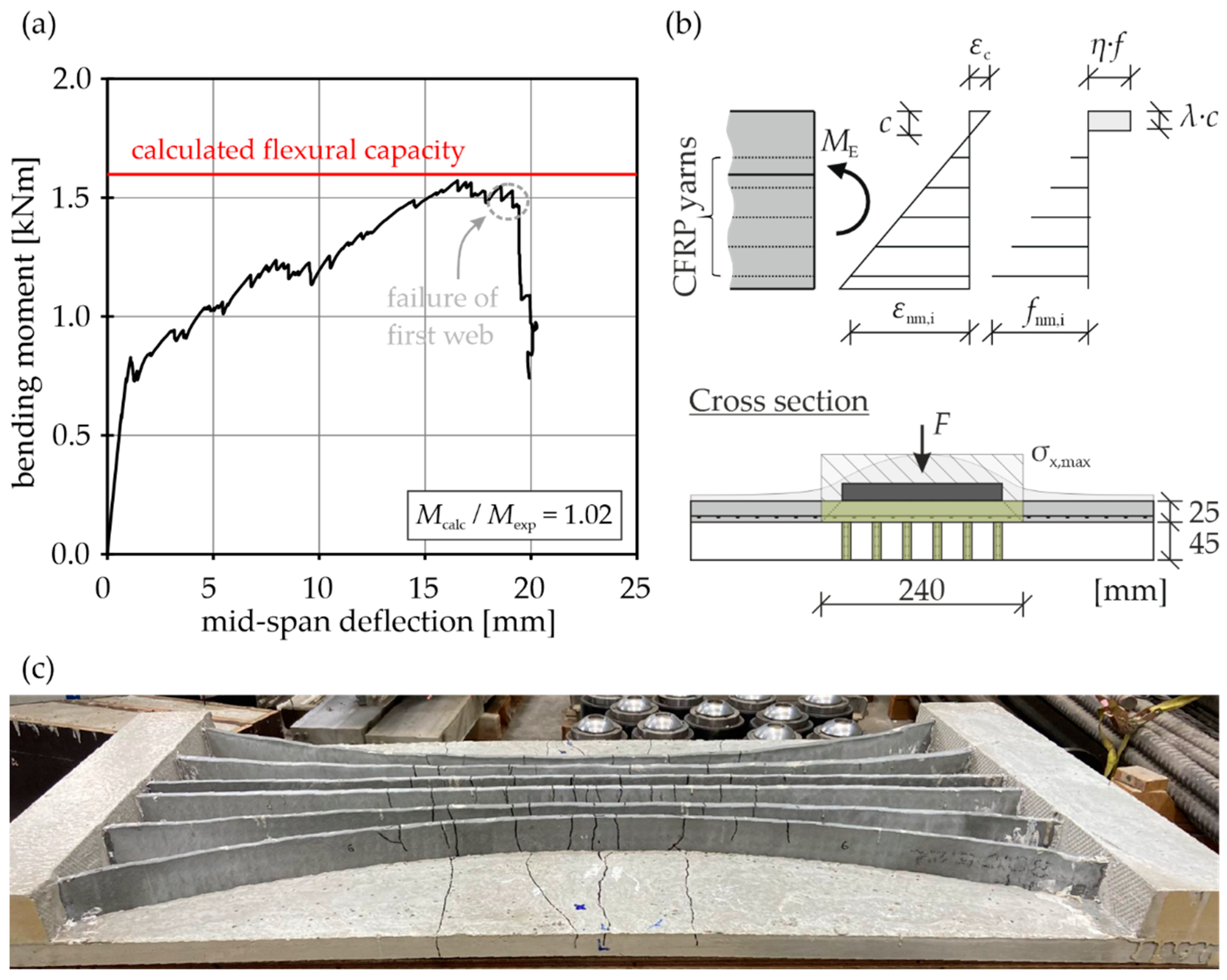
- Testing of the ExCRC slab demonstrator showed the sufficient strength of the joints between the slab and the webs, resulting in flexural failure of the webs. The flexural capacity of the tested ExCRC slab demonstrator could be accurately estimated by a simple iterative calculation.
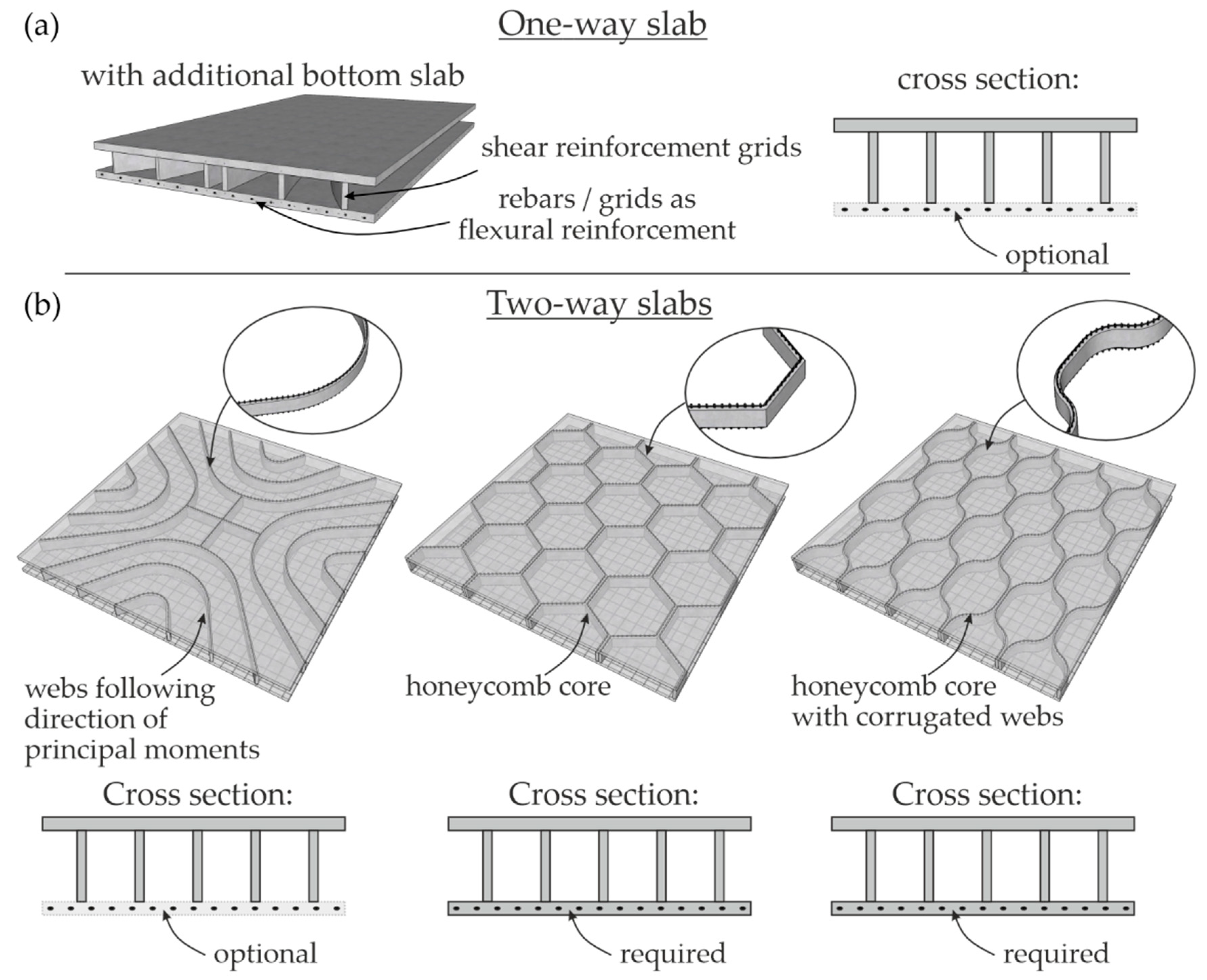
- Based on the test results, the technical requirements for the implementation of the innovative ribbed slab made of ExCRC on a plant scale for one-way and two-way slabs were demonstrated.
- The addition of a bottom concrete layer for the integration of longitudinal reinforcement and the use of corrugated extruded CRC webs for the realisation of a honeycomb core for the ceiling are important measures to further increase efficiency.
Author Contributions
Funding
Data Availability Statement
Acknowledgments
Conflicts of Interest
References
- Beckmann, B.; Bielak, J.; Bosbach, S.; Scheerer, S.; Schmidt, C.; Hegger, J.; Curbach, M. Collaborative research on carbon reinforced concrete structures in the CRC/TRR 280 project. Civ. Eng. Des. 2021, 3, 99–109. [Google Scholar] [CrossRef]
- Janani, R.; Lalithambigai, N. A critical literature review on minimization of material wastes in construction projects. Mater. Today Proc. 2021, 37, 3061–3065. [Google Scholar] [CrossRef]
- Spelter, A.; Bergmann, S.; Bielak, J.; Hegger, J. Long-Term Durability of Carbon-Reinforced Concrete: An Overview and Experimental Investigations. Appl. Sci. 2019, 9, 1651. [Google Scholar] [CrossRef]
- Tietze, M.; Kirmse, S.; Kahnt, A.; Schladitz, F.; Curbach, M. The ecological and economic advantages of carbon reinforced concrete—Using the C 3 result house CUBE especially the BOX value chain as an example. Civ. Eng. Des. 2022, 4, 79–88. [Google Scholar] [CrossRef]
- Bielak, J.; Spelter, A.; Will, N.; Claßen, M. Verankerungsverhalten textiler Bewehrungen in dünnen Betonbauteilen. BUST 2018, 113, 515–524. [Google Scholar] [CrossRef]
- Stark, A.; Classen, M.; Hegger, J. Bond behaviour of CFRP tendons in UHPFRC. Eng. Struct. 2019, 178, 148–161. [Google Scholar] [CrossRef]
- Morales Cruz, C. Crack-Distributing Carbon Textile Reinforced Concrete Protection Layers. Ph.D. Thesis, RWTH Aachen University, Aachen, Germany, 2020. [Google Scholar] [CrossRef]
- Zhang, M.; Deng, M. Tensile behavior of textile-reinforced composites made of highly ductile fiber-reinforced concrete and carbon textiles. J. Build. Eng. 2022, 57, 104824. [Google Scholar] [CrossRef]
- Bielak, J.; Schöneberg, J.; Classen, M.; Hegger, J. Shear capacity of continuous concrete slabs with CFRP reinforcement. Constr. Build. Mater. 2022, 320, 126117. [Google Scholar] [CrossRef]
- Liao, J.; Lin, X.-C.; Zhu, D.-H.; Zheng, Y.; Zeng, J.-J.; Ma, C.-L.; Zhao, H.-C. Behavior of FRP grid-reinforced ultra-high performance concrete (UHPC) pipes under lateral compression. Case Stud. Constr. Mater. 2023, 19, e02189. [Google Scholar] [CrossRef]
- Schladitz, F. Carbonbeton—Was ist schon möglich? Aktueller Stand der Entwicklung und Forschung. Beton Fachz. Bau Tech. 2019, 69, 156–161. [Google Scholar]
- Backes, J.G.; Schmidt, L.; Bielak, J.; Del Rosario, P.; Traverso, M.; Claßen, M. Comparative Cradle-to-Grave Carbon Footprint of a CFRP-Grid Reinforced Concrete Façade Panel. Sustainability 2023, 15, 11548. [Google Scholar] [CrossRef]
- Kalthoff, M.; Raupach, M.; Matschei, T. Extrusion and Subsequent Transformation of Textile-Reinforced Mortar Components—Requirements on the Textile, Mortar and Process Parameters with a Laboratory Mortar Extruder (LabMorTex). Buildings 2022, 12, 726. [Google Scholar] [CrossRef]
- Kalthoff, M.; Bosbach, S.; Matschei, T.; Raupach, M.; Claßen, M.; Hegger, J. Investigations on material-minimized slabs made of extruded carbon reinforced concrete. In Proceedings of the Fib International Congress 2022, Oslo, Norway, 12–16 June 2022. [Google Scholar]
- Kalthoff, M. Extruded Thin-Walled Textile Reinforced Concrete Components with Flexible Shape. Ph.D. Thesis, RWTH Aachen University, Aachen, Germany, 2023. [Google Scholar] [CrossRef]
- Alfani, R.; Guerrini, G.L. Rheological test methods for the characterization of extrudable cement-based materials—A review. Mat. Struct. 2005, 38, 239–247. [Google Scholar] [CrossRef]
- Perrot, A.; Rangeard, D.; Nerella, V.N.; Mechtcherine, V. Extrusion of cement-based materials—An overview. RILEM Tech. Lett. 2018, 3, 91–97. [Google Scholar] [CrossRef]
- Zhou, X.; Li, Z. Manufacturing cement-based materials and building products via extrusion: From laboratory to factory. Proc. Inst. Civ. Eng. Civ. Eng. 2015, 168, 11–16. [Google Scholar] [CrossRef]
- Meurer, M.; Classen, M. Mechanical Properties of Hardened 3D Printed Concretes and Mortars-Development of a Consistent Experimental Characterization Strategy. Materials 2021, 14, 752. [Google Scholar] [CrossRef]
- Händle, F. (Ed.) The Art of Ceramic Extrusion, 1st ed.; Springer International Publishing; Springer: Cham, Switzerland, 2019; ISBN 978-3-030-05254-6. [Google Scholar]
- Beeckman, J.W.L. Catalyst Engineering Technology: Fundamentals and Applications; Wiley: Hoboken, NJ, USA, 2020; ISBN 9781119634942. [Google Scholar]
- Kalthoff, M.; Raupach, M.; Matschei, T. Investigation of Rheological Test Methods for the Suitability of Mortars for Manufacturing of Textile-Reinforced Concrete Using a Laboratory Mortar Extruder (LabMorTex). Constr. Mater. 2022, 2, 217–233. [Google Scholar] [CrossRef]
- Lewis, W. Form-Finding Approach to Modelling Minimal Structural Forms, with Analogy to Nature. In Proceedings ISSA 2016: Innovative Structural Systems in Architecture, 3–5 November 2016, Wroclaw, Poland; Wroclaw Branch of the Polish Academy of Sciences: Wroclaw, Poland, 2016; pp. 39–42. [Google Scholar]
- Lewis, W.J. Tension cables in suspension bridges. A case of form-finding. In Tension Structures: Form and Behaviour, 2nd ed.; Lewis, W.J., Ed.; ICE Publishing: Leeds, UK, 2017; pp. 101–133. ISBN 978-0-7277-6173-6. [Google Scholar] [CrossRef]
- Smarslik, M.; Ahrens, M.A.; Mark, P. Toward holistic tension- or compression-biased structural designs using topology optimization. Eng. Struct. 2019, 199, 109632. [Google Scholar] [CrossRef]
- Hegger, J.; Herbrand, M.; Stark, A.; Classen, M. Betonbau der Zukunft: Leicht, filigran und nachhaltig. Bauing 2015, 90, 337–344. [Google Scholar] [CrossRef]
- Stark, A.; Classen, M.; Knorrek, C.; Camps, B.; Hegger, J. Sandwich panels with folded plate and doubly curved UHPFRC facings. Struct. Concr. 2018, 19, 1851–1861. [Google Scholar] [CrossRef]
- Liew, A.; López, D.L.; van Mele, T.; Block, P. Design, fabrication and testing of a prototype, thin-vaulted, unreinforced concrete floor. Eng. Struct. 2017, 137, 323–335. [Google Scholar] [CrossRef]
- Mata-Falcón, J.; Bischof, P.; Huber, T.; Anton, A.; Burger, J.; Ranaudo, F.; Jipa, A.; Gebhard, L.; Reiter, L.; Lloret-Fritschi, E.; et al. Digitally fabricated ribbed concrete floor slabs: A sustainable solution for construction. RILEM Tech. Lett. 2022, 7, 68–78. [Google Scholar] [CrossRef]
- Jayasinghe, A.; Orr, J.; Hawkins, W.; Ibell, T.; Boshoff, W.P. Comparing different strategies of minimising embodied carbon in concrete floors. J. Clean. Prod. 2022, 345, 131177. [Google Scholar] [CrossRef]
- Rippmann, M.; Liew, A.; van Mele, T.; Block, P. Design, fabrication and testing of discrete 3D sand-printed floor prototypes. Mater. Today Commun. 2018, 15, 254–259. [Google Scholar] [CrossRef]
- Antony, F.; Grießhammer, R.; Speck, T.; Speck, O. Sustainability assessment of a lightweight biomimetic ceiling structure. Bioinspir. Biomim. 2014, 9, 16013. [Google Scholar] [CrossRef]
- Classen, M.; Dressen, T. Experimental Investigations on Prestressed Concrete Beams with Openings. ACI Struct. J. 2015, 112, 221. [Google Scholar] [CrossRef]
- Halpern, A.B.; Billington, D.P.; Adriaenssens, S. The ribbed floor slab systems of pier luigi nervi. J. IASS 2013, 54, 127–136. [Google Scholar]
- Rempel, S.; Will, N.; Hegger, J.; Beul, P. Filigrane Bauwerke aus Textilbeton. Beton Stahlbetonbau 2015, 110, 83–93. [Google Scholar] [CrossRef]
- Furche, J.; Bauermeister, U. Beton-Kalender 2016: Schwerpunkte: Beton im Hochbau, Silos und Behälter, 1st ed.; Ernst Wilhelm & Sohn: Berlin, Germany, 2015; ISBN 978-3-433-03074-5. [Google Scholar]
- Roggendorf, T.; Hegger, J. Zur Querkrafttragfähigkeit von Spannbeton-Fertigdecken bei biegeweicher Lagerung–Teil 1: Modellentwicklung. Beton Stahlbetonbau 2011, 106, 531–539. [Google Scholar] [CrossRef]
- Abramski, M.; Albert, A.; Pfeffer, K.; Schnell, J. Experimentelle und numerische Untersuchungen zum Tragverhalten von Stahlbetondecken mit kugelförmigen Hohlkörpern. Beton Stahlbetonbau 2010, 105, 349–361. [Google Scholar] [CrossRef]
- Ackermann, F.P. Load-Bearing Behaviour of Steel Fibre Reinforced Continuous Composite Slabs. Ph.D. Thesis, Technische Universität Kaiserslautern, Kaiserslautern, Germany, 2010. ISBN 9783941438484. [Google Scholar]
- Hegger, J.; Claßen, M.; Schaumann, P.; Sothmann, J.; Feldmann, M.; Döring, B. Entwicklung einer integrierten Verbunddecke für nachhaltige Stahlbauten. Stahlbau 2013, 82, 11–17. [Google Scholar] [CrossRef]
- Hegger, J.; Kerkeni, N.; Roggendorf, T. Zum Tragverhalten von Slim-Floor-Konstruktionen. Beton- Stahlbetonbau Sonderdr. Flachdecken 2008, 1, 5–14. [Google Scholar] [CrossRef]
- Nervi, P.L.; Rogers, E.N.; Joedicke, J.P. Bauten und Projekte; Gerd Hatje: Stuttgart, Germany, 1957. [Google Scholar]
- Huber, T.; Burger, J.; Mata-Falcón, J.; Kaufmann, W. Structural design and testing of material optimized ribbed RC slabs with 3D printed formwork. Struct. Concr. 2023, 24, 1932–1955. [Google Scholar] [CrossRef]
- Hansemann, G.; Schmid, R.; Holzinger, C.; Tapley, J.; Kim, H.H.; Sliskovic, V.; Freytag, B.; Trummer, A.; Peters, S. Additive fabrication of concrete elements by robots: Lightweight concrete ceiling. In Fabricate 2020: Making Resilient Architecture; Burry, J., Sabin, J., Sheil, B., Skavara, M., Eds.; UCL Press: London, UK, 2020. [Google Scholar]
- Bedarf, P.; Szabo, A.; Zanini, M.; Heusi, A.; Dillenburger, B. Robotic 3D printing of mineral foam for a lightweight composite concrete slab. In Proceedings of the 26th International Conference of the Association for Computer-Aided Architectural Design Research in Asia (CAADRIA 2021), Hong Kong, China, 29 March–1 April 2021; Association for Computer-Aided Architectural Design Research in Asia (CAADRIA): Hong Kong, China, 2022; pp. 61–70. [Google Scholar]
- Kalthoff, M.; Bosbach, S.; Backes, J.G.; Morales Cruz, C.; Claßen, M.; Traverso, M.; Raupach, M.; Matschei, T. Fabrication of lightweight, carbon textile reinforced concrete components with internally nested lattice structure using 2-layer extrusion by LabMorTex. Constr. Build. Mater. 2023, 395, 132334. [Google Scholar] [CrossRef]
- Bosbach, S.; Hegger, J.; Claßen, M. Dowel action of CFRP shear reinforcement in carbon reinforced concrete: (under review). Constr. Build. Mater. 2023. [Google Scholar]
- Bielak, J. Shear in Slabs with Non-Metallic Reinforcement. Ph.D. Thesis, RWTH Aachen University, Aachen, Germany, 2021. [Google Scholar] [CrossRef]
- Schneider, K.; Butler, M.; Mechtcherine, V. Carbon Concrete Composites C 3—Nachhaltige Bindemittel und Betone für die Zukunft. Beton Stahlbetonbau 2017, 112, 784–794. [Google Scholar] [CrossRef]
- DIN EN 196-1:2016-11; Methods of Testing Cement—Part 1: Determination of Strength. German Version EN 196-1:2016. Beuth Verlag GmbH: Berlin, Germany, 2016. [CrossRef]
- Kalthoff, M.; Raupach, M.; Matschei, T. Investigation into the Integration of Impregnated Glass and Carbon Textiles in a Laboratory Mortar Extruder (LabMorTex). Materials 2021, 14, 7406. [Google Scholar] [CrossRef]
- DAfStb-Heft 240; Deutscher Ausschuss für Stahlbeton. Ernst & Sohn: Hoboken, NJ, USA, 1991.
- Kalthoff, M.; Raupach, M.; Matschei, T. Materialminimiertes Bauen mit extrudiertem Textilbeton. Beton 2022, 72, 195–198. [Google Scholar]
- Beckers, J.; Kalthoff, M.; Morales Cruz, C.; Matschei, T. Possibilities of extrusion production in concrete construction. In Beiträge zur 10. DAfStb-Jahrestagung mit 62. Forschungskolloquium 26–27. September 2023; Hegger, J., Claßen, M., Raupach, M., Matschei, T., Schmidt, M., Alvarez y Leal, A., Eds.; RWTH Aachen University: Aachen, Germany, 2023; pp. 161–169. [Google Scholar] [CrossRef]
- Rempel, S.; Ricker, M.; Hegger, J. Biegebemessungsmodell mit einer geschlossenen und iterativen Lösung für Textilbetonbauteile. Beton Stahlbetonbau 2020, 115, 218–230. [Google Scholar] [CrossRef]
- Preinstorfer, P.; Kromoser, B.; Kollegger, J. Flexural behaviour of filigree slab elements made of carbon reinforced UHPC. Constr. Build. Mater. 2019, 199, 416–423. [Google Scholar] [CrossRef]
- Papila, M.; Atilgan, A.R. All-composite honeycomb core sandwich structures: Master curves for stiffness-based design. Forces Mech. 2022, 6, 100066. [Google Scholar] [CrossRef]
- Goswami, S. On the Prediction of Effective Material Properties of Cellular Hexagonal Honeycomb Core. J. Reinf. Plast. Compos. 2006, 25, 393–405. [Google Scholar] [CrossRef]
- Ghanbari-Ghazijahani, T.; Kasebahadi, M.; Hassanli, R.; Classen, M. 3D printed honeycomb cellular beams made of composite materials (plastic and timber). Constr. Build. Mater. 2022, 315, 125541. [Google Scholar] [CrossRef]


| Parameter | Unit | Extrusion (C1) | Casting (C2) |
|---|---|---|---|
| CEM I 42.5 R | kg/m3 | 700 | - |
| CEM II/C-M | - | 707 | |
| Silica fume powder | 70 | - | |
| Fly ash | 210 | - | |
| Water | 278 | 165 | |
| Sand 2.0–4.0 mm | - | 596 | |
| Sand 1.0–2.0 mm | - | 149 | |
| Sand 0.5–1.0 mm | - | 227 | |
| Sand 0.1–0.5 mm | 670 | 220 | |
| Sand 0–0.250 mm | - | 296 | |
| Quartz powder 0–0.250 mm | 278 | - | |
| Methylcellulose | 7.0 | - | |
| Superplasticiser | M% of cement | - | 1.53 |
| PVA microfibres, ∅/L = 0.026/6 mm | Vol.—% | 0.50 | - |
| Compressive strength at 28 d | MPa | 65 | 100 |
| Flexural tensile strength at 28 d | 11 | 11 | |
| Intensity of CO2 per unit of compressive strength | kgCO2eq/(m3·MPa) | 7.3 | 3.0 |
| Manufacturer’s Designation | Impregnation | Tensile Strength 1 | Young’s Modulus 1 | Mesh Size 1 | Cross-Section 1 |
|---|---|---|---|---|---|
| [MPa] | [GPa] | [mm] | [mm2/m] | ||
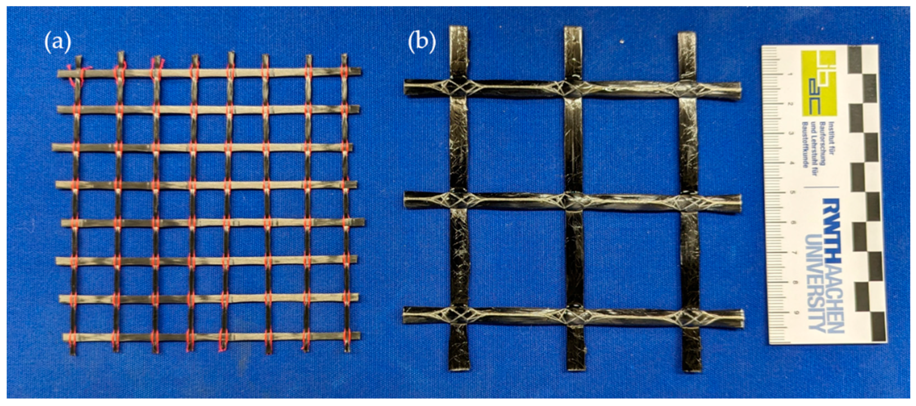
| SITgrid044 KK | PA | 2000/1840 | 150/150 | 12 | 35.3 |
| Q95-CCE-38-E5 | Epoxy resin | 3710/3490 | 231/244 | 38 | 95.0 |
Disclaimer/Publisher’s Note: The statements, opinions and data contained in all publications are solely those of the individual author(s) and contributor(s) and not of MDPI and/or the editor(s). MDPI and/or the editor(s) disclaim responsibility for any injury to people or property resulting from any ideas, methods, instructions or products referred to in the content. |
© 2023 by the authors. Licensee MDPI, Basel, Switzerland. This article is an open access article distributed under the terms and conditions of the Creative Commons Attribution (CC BY) license (https://creativecommons.org/licenses/by/4.0/).
Share and Cite
Bosbach, S.; Kalthoff, M.; Morales Cruz, C.; Adam, V.; Matschei, T.; Classen, M. Digital Prefabrication of Lightweight Building Elements for Circular Economy: Material-Minimised Ribbed Floor Slabs Made of Extruded Carbon Reinforced Concrete (ExCRC). Buildings 2023, 13, 2928. https://doi.org/10.3390/buildings13122928
Bosbach S, Kalthoff M, Morales Cruz C, Adam V, Matschei T, Classen M. Digital Prefabrication of Lightweight Building Elements for Circular Economy: Material-Minimised Ribbed Floor Slabs Made of Extruded Carbon Reinforced Concrete (ExCRC). Buildings. 2023; 13(12):2928. https://doi.org/10.3390/buildings13122928
Chicago/Turabian StyleBosbach, Sven, Matthias Kalthoff, Cynthia Morales Cruz, Viviane Adam, Thomas Matschei, and Martin Classen. 2023. "Digital Prefabrication of Lightweight Building Elements for Circular Economy: Material-Minimised Ribbed Floor Slabs Made of Extruded Carbon Reinforced Concrete (ExCRC)" Buildings 13, no. 12: 2928. https://doi.org/10.3390/buildings13122928