

Robot-Assisted Manufacturing Technology for 3D Non-Metallic Reinforcement Structures in the Construction Applications

 , , , , and
Abstract
:1. Introduction
- A.
- Robot-assisted yarn deposition technologies for non-metallic reinforcement structures in the construction industry
- B.
- Robot-assisted yarn deposition technologies for fiber-reinforced plastic structures in other economic sectors
2. Materials and Methods
2.1. Materials
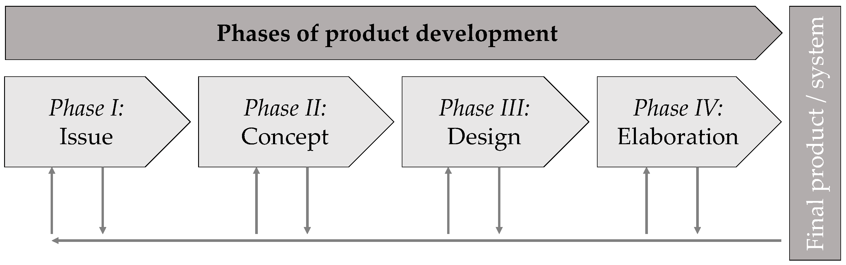
2.2. Methods
- Phase I:
- Requirements list
- Phase II:
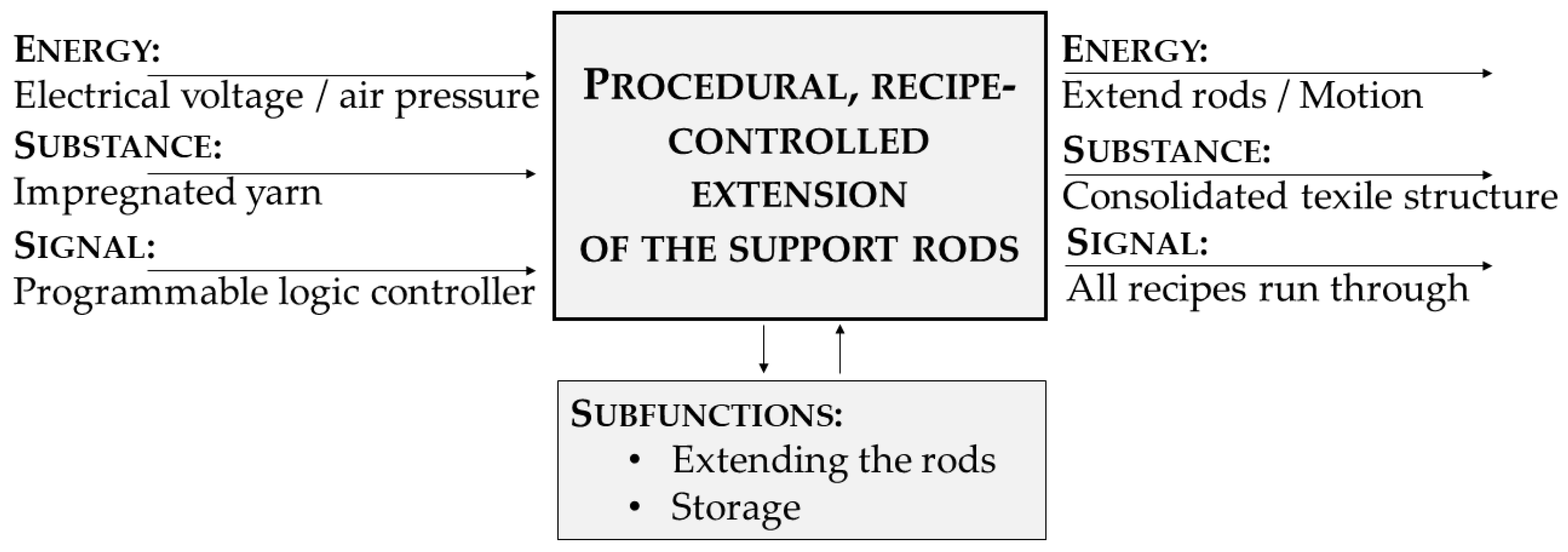
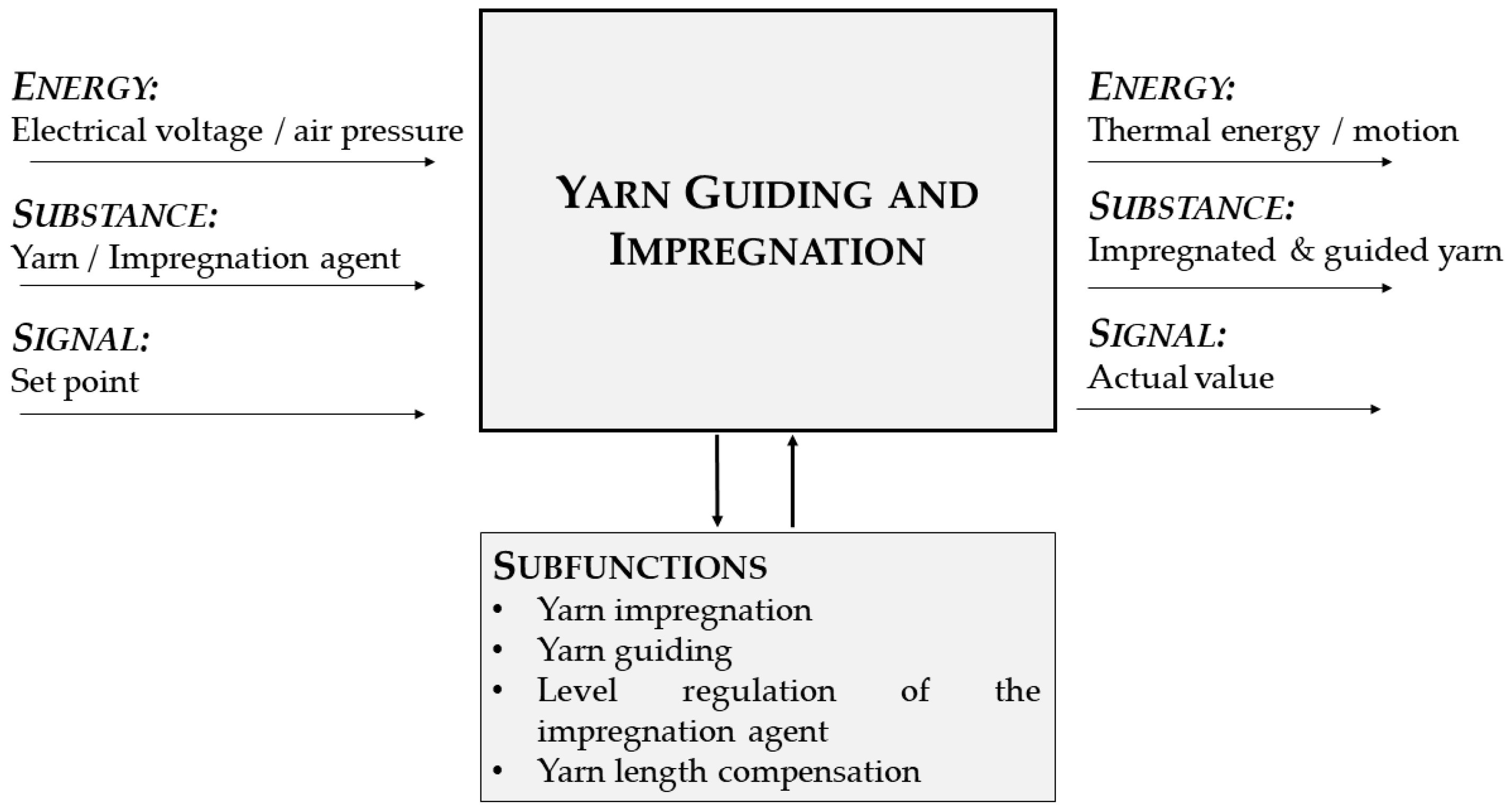
- Functional structures & principle solutions
- Phase III:
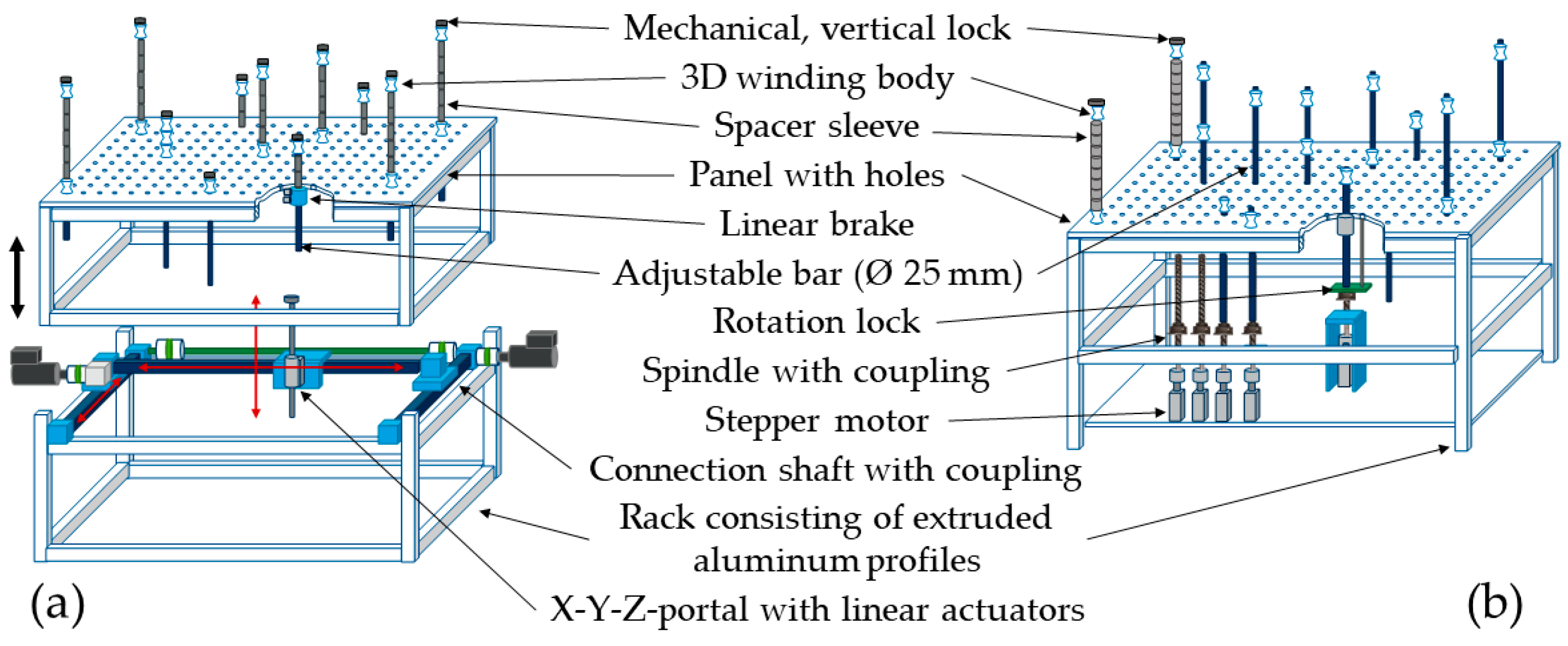
- Modular structures & preliminary designs (variants of possible solution combinations)
- Phase IV:
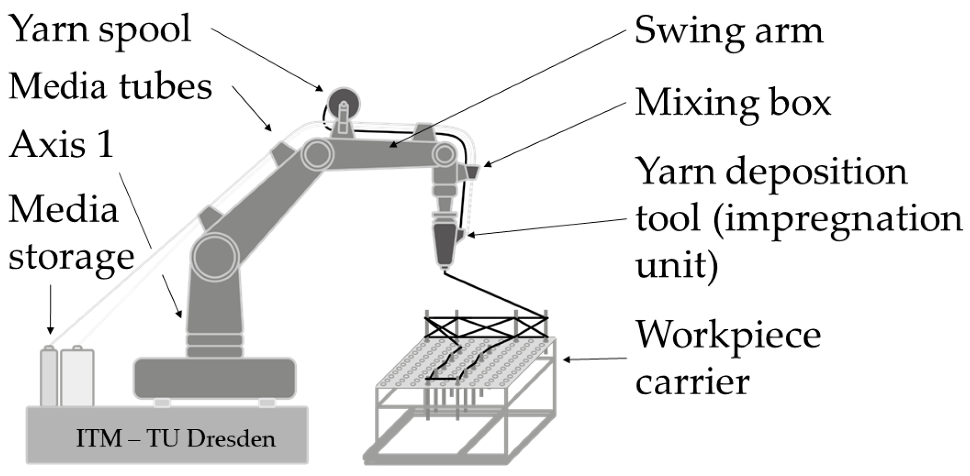
- Overall design based on the preferred solution
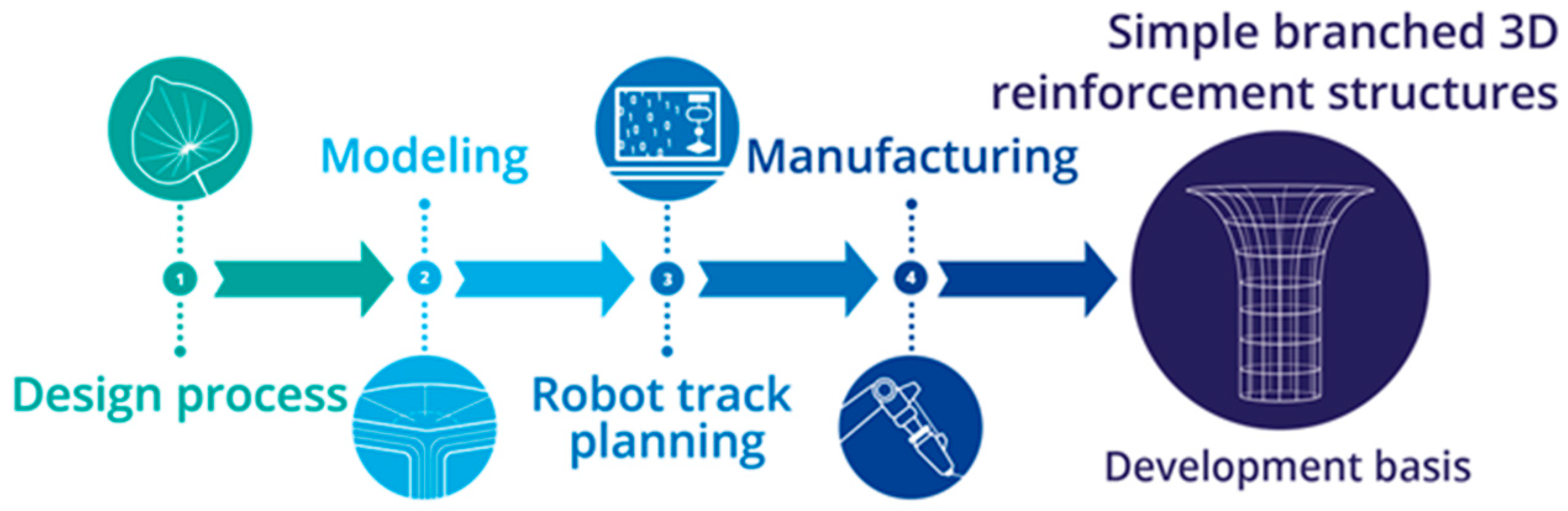
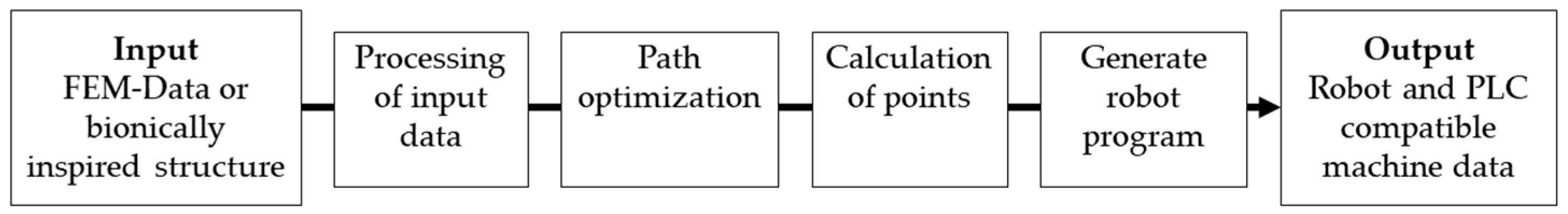
3. Development Process
4. Results
5. Discussion
Author Contributions
Funding
Data Availability Statement
Acknowledgments
Conflicts of Interest
References
- UN Environment Programme. 2021 Global Status Report For Buildings and Construction. 2021. Available online: https://globalabc.org/resources/publications/2021-global-status-report-buildings-and-construction (accessed on 24 September 2023).
- Beyond Zero Emissions. Rethinking Cement: Zero Carbon Industry Plan; Beyond Zero Emissions Inc: Fitzroy, Victoria, 2017; ISBN 978-0-9923580-2-0. [Google Scholar]
- Crippa, M.; Oreggioni, G.; Guizzardi, D.; Muntean, M.; Schaaf, E.; Lo Vullo, E.; Solazzo, E.; Monforti-Ferrario, F.; Olivier, J.; Vignati, E. Fossil CO2 and GHG Emissions of All World Countries: 2019 Report; Publications Office of the European Union: Luxembourg, 2019; ISBN 978-92-76-11100-9. [Google Scholar]
- UN Environment Programme. Emissions Gap Report 2022. 2022. Available online: https://www.unep.org/resources/emissions-gap-report-2022 (accessed on 24 September 2023).
- Beckmann, B.; Bielak, J.; Scheerer, S.; Schmidt, C.; Hegger, J.; Curbach, M. Standortübergreifende Forschung zu Carbonbetonstrukturen im SFB/TRR 280. Bautechnik 2021, 98, 232–242. [Google Scholar] [CrossRef]
- Scheerer, S. Was ist Textilbeton? Eine kurze Einführung in das Thema. Beton und Stahlbetonbau 2015, 110, 4–7. [Google Scholar] [CrossRef]
- Spelter, A.; Bergmann, S.; Bielak, J.; Hegger, J. Long-Term Durability of Carbon-Reinforced Concrete: An Overview and Experimental Investigations. Appl. Sci. 2019, 9, 1651. [Google Scholar] [CrossRef]
- Seifert, W.; Lieboldt, M. Ressourcenverbrauch im globalen Stahlbetonbau und Potenziale der Carbonbetonbauweise. Beton-Stahlbetonbau 2020, 115, 469–478. [Google Scholar] [CrossRef]
- Friese, D.; Hahn, L.; Cherif, C. Biologically Inspiried Load Adapted 3D Textile Reinforcement Structures. MSF 2022, 1063, 101–110. [Google Scholar] [CrossRef]
- Sacher, M.; Lautenschläger, T.; Kempe, A.; Neinhuis, C. Umbrella leaves-Biomechanics of transition zone from lamina to petiole of peltate leaves. Bioinspir. Biomim. 2019, 14, 46011. [Google Scholar] [CrossRef]
- Wunnenberg, J.; Rjosk, A.; Neinhuis, C.; Lautenschläger, T. Strengthening Structures in the Petiole-Lamina Junction of Peltate Leaves. Biomimetics 2021, 6, 25. [Google Scholar] [CrossRef]
- Otto, J.; Kortmann, J.; Krause, M. Wirtschaftliche Perspektiven von Beton-3D-Druckverfahren. Beton Und Stahlbetonbau 2020, 115, 586–597. [Google Scholar] [CrossRef]
- Goldmann, M. Betondruck: Deutschlands Erstes Wohnhaus Aus Dem 3D-Drucker. Available online: https://www.dabonline.de/2020/11/26/haus-3d-drucker-betondruck-deutschlands-erstes-wohnhaus-gedruckt-beckum-beton-peri/ (accessed on 24 September 2023).
- Cherif, C. (Ed.) Textile Materials for Lightweight Constructions; Springer: Berlin, Heidelberg, 2016; ISBN 978-3-662-46340-6. [Google Scholar]
- Hahn, L.; Zierold, K.; Golla, A.; Friese, D.; Rittner, S. 3D Textiles Based on Warp Knitted Fabrics: A Review. Materials 2023, 16, 3680. [Google Scholar] [CrossRef]
- Ji, W.; Wang, L. Industrial robotic machining: A review. Int. J. Adv. Manuf. Technol. 2019, 103, 1239–1255. [Google Scholar] [CrossRef]
- Von Zuben, M.; Cherif, C. Robot based Technology for the Production novel Resource-Saving and Cost-Efficient Textile Reinforcement Structures for Direct further Proceedings into Prefabricated Parts. In Proceedings of the 19th World Textile Conference on Textiles at the Crossroads, AUTEX2019, Ghent, Belgium, 11–15 June 2019. [Google Scholar]
- Mechtcherine, V.; Michel, A.; Liebscher, M.; Schneider, K.; Großmann, C. Neue Carbonfaserbewehrung für digitalen automatisierten Betonbau. Beton und Stahlbetonbau 2019, 114, 947–955. [Google Scholar] [CrossRef]
- Rittner, S.; Grauer, O.; Kahnt, A.; Holschemacher, K. Entwicklung und Fertigung nichtmetallischer Bewehrungen im automatisierten Prozess. In Betonbauteile 2023: Hintergründe, Auslegungen, Neue Tendenzen im Betonbau; Holschemacher, K., Ed.; Beuth Verlag GmbH: Berlin, Germany; Wien, Austria; Zürich, Switzerland, 2023; ISBN 978-3-410-31562-9. [Google Scholar]
- Knoch, E. Entwicklung einer Hochgeschwindigkeits-Garnablage zur Fertigung von Textilbewehrungen. In Proceedings of the 15. Carbon- und Textilbetontage, Dresden, Germany, 19–20 September 2023. [Google Scholar]
- Schneider, K.; Michel, A.; Liebscher, M.; Terreri, L.; Hempel, S.; Mechtcherine, V. Mineral-impregnated carbon fibre reinforcement for high temperature resistance of thin-walled concrete structures. Cem. Concr. Compos. 2019, 97, 68–77. [Google Scholar] [CrossRef]
- Hack, N.; Bahar, M.; Hühne, C.; Lopez, W.; Gantner, S.; Khader, N.; Rothe, T. Development of a Robot-Based Multi-Directional Dynamic Fiber Winding Process for Additive Manufacturing Using Shotcrete 3D Printing. Fibers 2021, 9, 39. [Google Scholar] [CrossRef]
- Rothe, T.; Pösch, J.; Gantner, S.; Hack, N.; Hühne, C. (Eds.) Optimization of Tensile Properties and Bond Behaviour to Concrete of Fibre Reinforcement Strands Produced Within a Dynamic Fibre Winding Process; Zenodo: Geneva, Switzerland, 2023. [Google Scholar]
- Minsch, N.; Müller, M.; Gereke, T.; Nocke, A.; Cherif, C. Novel fully automated 3D coreless filament winding technology. J. Compos. Mater. 2018, 52, 3001–3013. [Google Scholar] [CrossRef]
- Knippers, J.; Koslowski, V.; Solly, J.; Fildhuth, T. Modular coreless filament winding for lightweight systems in architecture. In Proceedings of the CICE 2016 8th International Conference on Fibre-Reinforced Polymer (FRP) Composites in Civil Engineering, Hong Kong, China, 14–16 December 2016. [Google Scholar]
- Solly, J.; Frueh, N.; Saffarian, S.; Prado, M. ICD/ITKE Research Pavilion 2016/2017: Integrative Design of a Composite Lattice Cantilever. In Proceedings of the IASS 2018 Creativity in Structural Design, Boston, MA, USA, 16–18 July 2018. [Google Scholar]
- Gil Pérez, M.; Guo, Y.; Knippers, J. Integrative material and structural design methods for natural fibres filament-wound composite structures: The LivMatS pavilion. Mater. Des. 2022, 217, 110624. [Google Scholar] [CrossRef]
- Mindermann, P.; Gil Pérez, M.; Knippers, J.; Gresser, G.T. Investigation of the Fabrication Suitability, Structural Performance, and Sustainability of Natural Fibers in Coreless Filament Winding. Materials 2022, 15, 3260. [Google Scholar] [CrossRef] [PubMed]
- Friese, D.; Scheurer, M.; Hahn, L.; Gries, T.; Cherif, C. Textile reinforcement structures for concrete construction applications––A review. J. Compos. Mater. 2022, 56, 4041–4064. [Google Scholar] [CrossRef]
- Teijin Limited. Tenax Filament Yarn: Technical Datasheet. Available online: https://www.teijincarbon.com/fileadmin/PDF/Datenblätter_en/Product_Data_Sheet_TSG01en__EU_Filament_.pdf (accessed on 24 September 2023).
- Giessmann. Substrat Und Textilbeschichtung; Springer: Berlin/Heidelberg, Germany, 2019; ISBN 978-3-662-58493-4. [Google Scholar]
- Zhao, J.; Liebscher, M.; Schneider, K.; Junger, D.; Mechtcherine, V. Influence of Processing Conditions on the Mechanical Behavior of Mineral-Impregnated Carbon-Fiber (MCF) Made with Geopolymer. In Proceedings of the 10th International Conference on FRP Composites in Civil Engineering, Istanbul, Turkey, 8–10 December 2021; Ilki, A., Ispir, M., Inci, P., Eds.; Springer International Publishing: Cham, Switzerland, 2022; pp. 1173–1182, ISBN 978-3-030-88165-8. [Google Scholar]
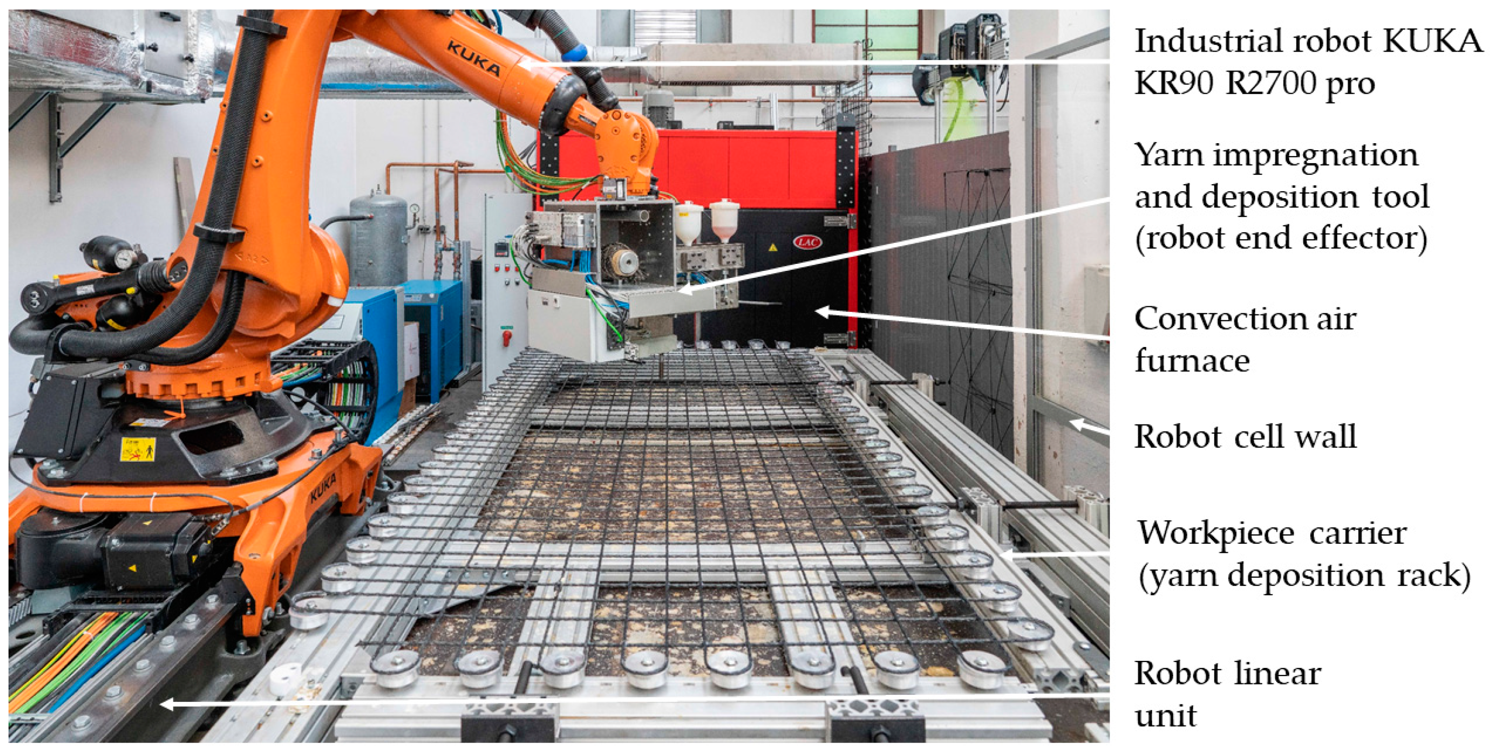
- KUKA Deutschland GmbH. KUKA KR 90 R2700 Pro: Technical Data Sheet. Available online: https://www.kuka.com (accessed on 24 September 2023).
- KUKA Deutschland GmbH. KUKA Lineareinheit KL 4000: Technical Data Sheet. Available online: https://www.kuka.com (accessed on 24 September 2023).
- VDI Verein Deutscher Ingenieure, e.V. Design of Technical Products and Systems-Model of Product Design; Düsseldorf. 2019. Available online: https://www.vdi.de/richtlinien/details/vdi-2221-blatt-1-entwicklung-technischer-produkte-und-systeme-modell-der-produktentwicklung (accessed on 24 September 2023).
- Friese, D.; Mersch, J.; Hahn, L.; Cherif, C. Development of a Yarn Guiding and Impregnation Technology for Robot-Assisted Fiber Manufacturing of 3D Textile Reinforcement Structures. In Proceedings of the 11th International Conference on Fiber-Reinforced Polymer (FRP) Composites in Civil Engineering (CICE 2023), Rio de Janeiro, Brazil, 23–26 July 2023. [Google Scholar]
- Karur, K.; Sharma, N.; Dharmatti, C.; Siegel, J.E. A Survey of Path Planning Algorithms for Mobile Robots. Vehicles 2021, 3, 448–468. [Google Scholar] [CrossRef]
- Dreifus, G.; Goodrick, K.; Giles, S.; Patel, M.; Foster, R.M.; Williams, C.; Lindahl, J.; Post, B.; Roschli, A.; Love, L.; et al. Path Optimization Along Lattices in Additive Manufacturing Using the Chinese Postman Problem. 3D Print. Addit. Manuf. 2017, 4, 98–104. [Google Scholar] [CrossRef]
- Neef, T.; Müller, S.; Mechtcherine, V. 3D-Druck mit Carbonbeton: Technologie und die ersten Untersuchungsergebnisse. Beton und Stahlbetonbau 2020, 115, 943–951. [Google Scholar] [CrossRef]


| Fiber Material | Filament Diameter in µm | Density in g/cm3 | Tensile Strength in N/mm2 | Breaking Strain in % | Young’s Modulus in 103 × N/mm2 |
|---|---|---|---|---|---|
| Carbon | 7 | 1.77 | 4300 | 1.7 | 250 |
| Impregnation Category | Impregnation Subcategory | Impregnation Material | Processing Temperature in °C |
|---|---|---|---|
| Impregnation based on polymers | Thermosetting matrix | Epoxy resin | 18–180 |
| Aqueous dispersion | Based on acrylate | 150 | |
| Based on polystyrene | 150–160 | ||
| Based on styrene-butadiene | 130–160 | ||
| Based on polyurethane | 120 | ||
| Impregnation based on minerals | Cement-based matrix | Micro-cement and micro-silica suspension | >0 |
| Geopolymer-based matrix | Metakaolin and potassium silicate solution | 60–75 |
| Feature | Type | Values, Data, Explanation |
|---|---|---|
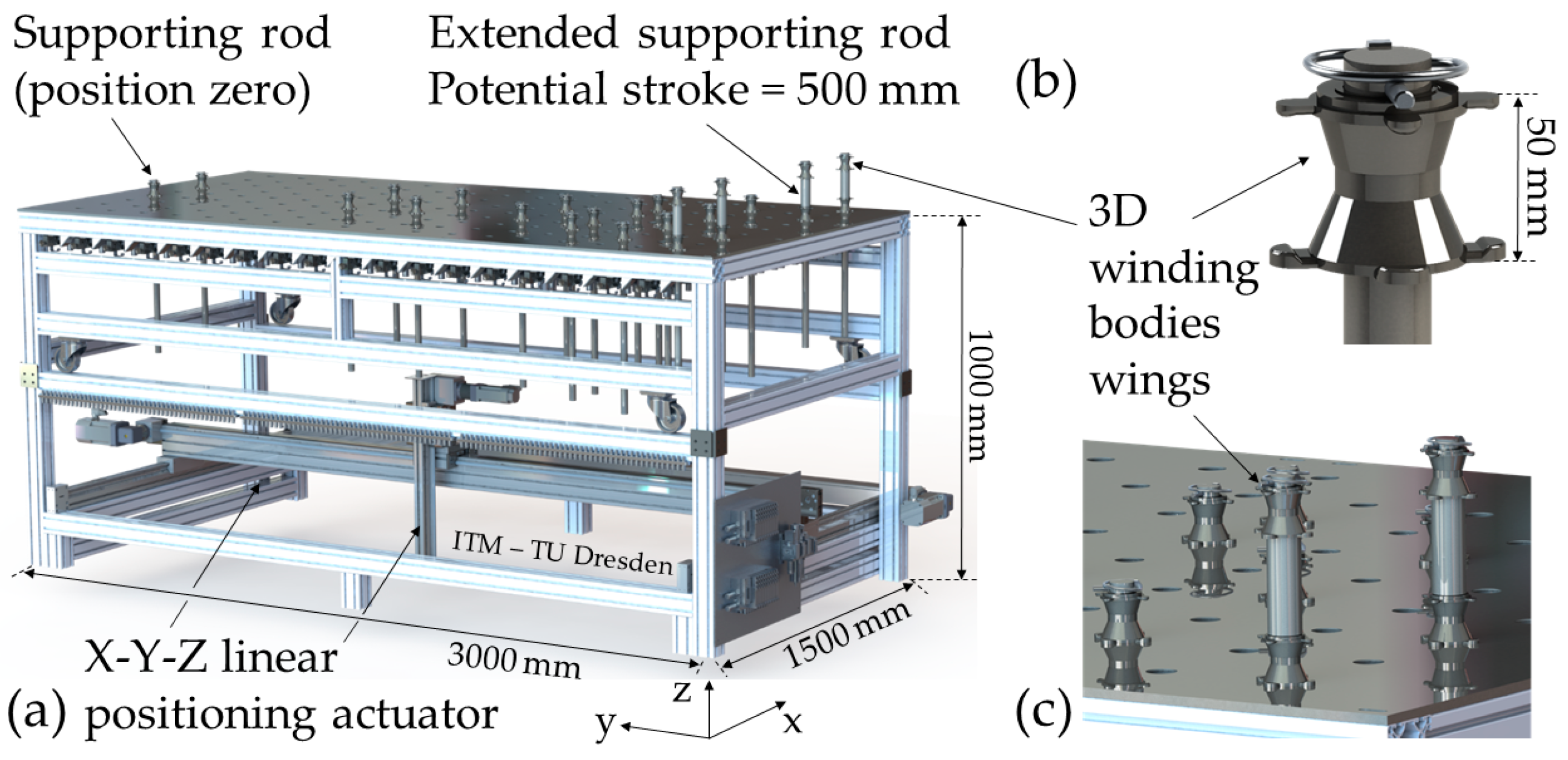
| Geometry | F | Maximum dimensions (width × length × height): 1750 mm × 3250 mm × 1700 mm |
| Statistics | F | Bending stiffness—maximum displacement tolerance of the support rod under load (bending moment of 25 Nm): 5 mm |
| Yarn deposition flexibility | D | Granularity of the hole matrix: 50 mm |
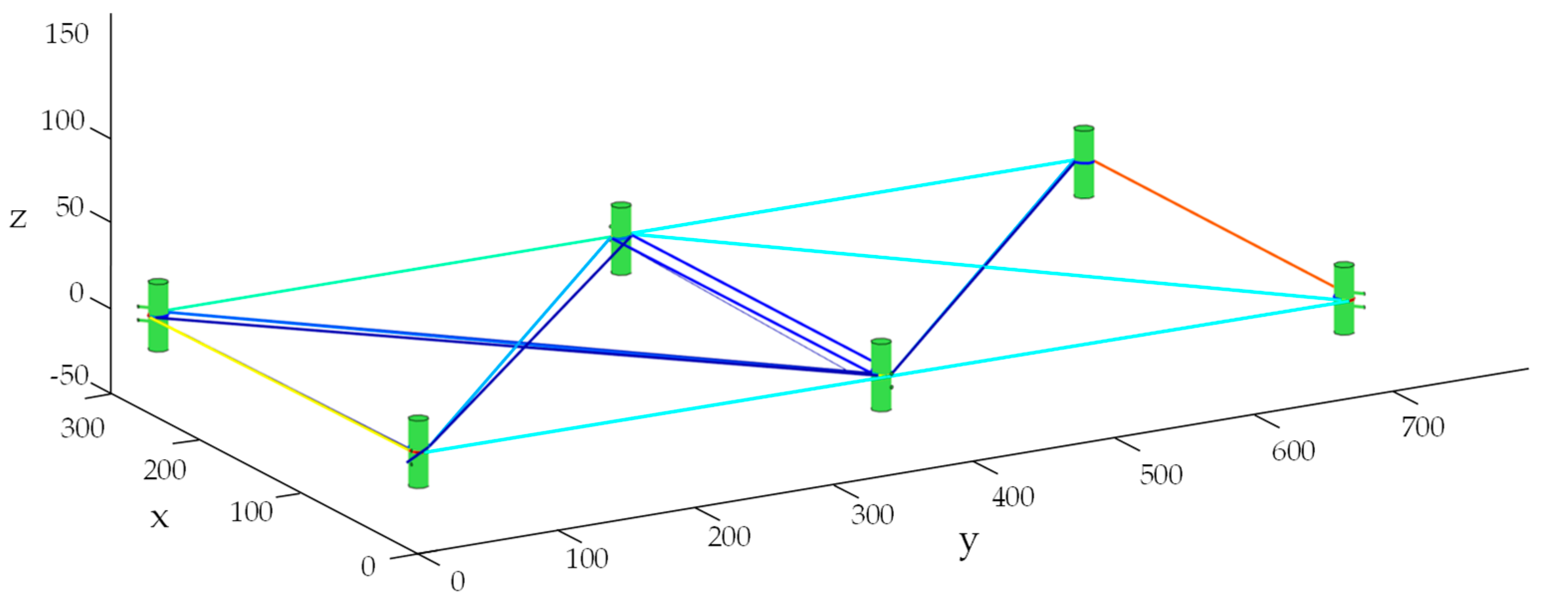
| Position accuracy | F | Predetermined position grid for winding bodies: 50 mm in z-direction; universal winding body topology |
| Universality | F | Support points are provided according to the textile topology to be deposited |
| Reusability | D | Complete demoldability of the consolidated FRP structure |
| Process temperature | M | Up to 200 °C (e.g., hardening of aqueous polymer dispersion) |
| Mobility | D | Possibility of transferring the deposited, fixed textile structure into the downstream process step (e.g., convection oven) |
| Yarn storage capacity | M | Minimum 5 carbon fiber heavy tows (area cross-section of 10.2 mm2) |
| Geometric winding body specifications | D | Rounded edges; minimum edge radius of 10 mm |
| Automation and control technologies | F | Individual controllability of the support points (in terms of avoiding collisions and winding feasibility) |
| Feature | Type | Values, Data, Explanation |
|---|---|---|
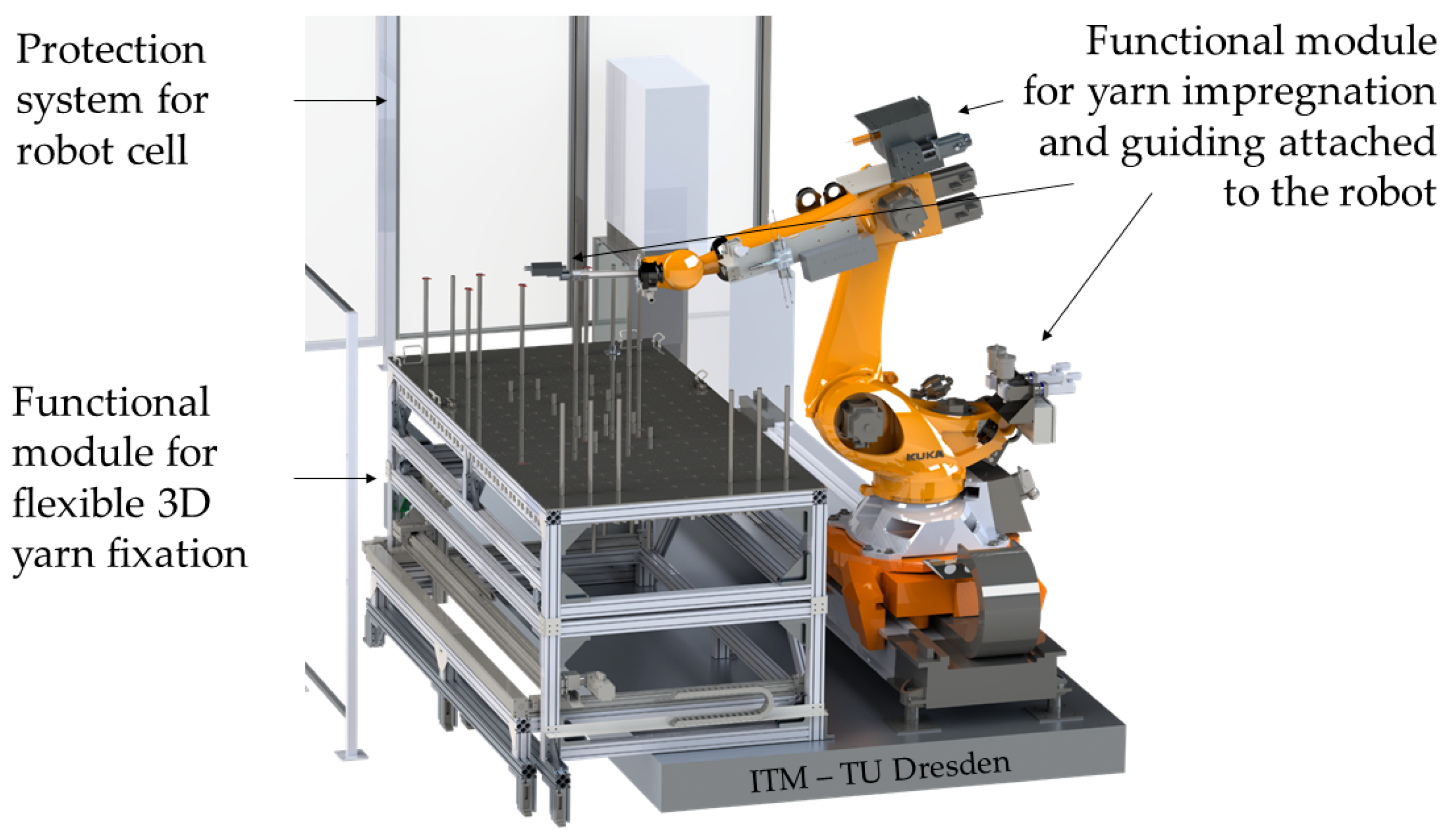
| Geometry | F | Minimum assembly space; closed geometry of the impregnation box |
| Universality | F | Flexibility in material selection (impregnation agent, fiber material, yarn count) |
| Reusability | F | Simplicity in cleaning |
| Yarn compensation capacity | F | Active and passive compensation unit; maximum fiber tensile force: 50 N |
| Yarn feeding | M | Active and electronically controlled decoiler (controlled by yarn take-off path) |
| Yarn impregnation process | M | Optimum filament impregnation (validated by grinding patterns and computer tomographic scans) |
| Impregnation agent mixing | M | Passive mixing via static mixing helix |
| Impregnation agent return | D | Impregnation circuit (improvement of mixing and avoidance of suspended matter deposition) |
| Delivery tube | M | Length: 50–150 mm; maximum outer tube diameter: 20 mm; minimum hole diameter: 2.2 mm (depending on yarn)High bending stiffness: displacement of the yarn outfeed center under load less than 1 mm |
| Process temperature | F | 160 °C |
Disclaimer/Publisher’s Note: The statements, opinions and data contained in all publications are solely those of the individual author(s) and contributor(s) and not of MDPI and/or the editor(s). MDPI and/or the editor(s) disclaim responsibility for any injury to people or property resulting from any ideas, methods, instructions or products referred to in the content. |
© 2023 by the authors. Licensee MDPI, Basel, Switzerland. This article is an open access article distributed under the terms and conditions of the Creative Commons Attribution (CC BY) license (https://creativecommons.org/licenses/by/4.0/).
Share and Cite
Friese, D.; Hahn, L.; Le Xuan, H.; Mersch, J.; Neef, T.; Mechtcherine, V.; Cherif, C. Robot-Assisted Manufacturing Technology for 3D Non-Metallic Reinforcement Structures in the Construction Applications. Buildings 2023, 13, 2748. https://doi.org/10.3390/buildings13112748
Friese D, Hahn L, Le Xuan H, Mersch J, Neef T, Mechtcherine V, Cherif C. Robot-Assisted Manufacturing Technology for 3D Non-Metallic Reinforcement Structures in the Construction Applications. Buildings. 2023; 13(11):2748. https://doi.org/10.3390/buildings13112748
Chicago/Turabian StyleFriese, Danny, Lars Hahn, Hung Le Xuan, Johannes Mersch, Tobias Neef, Viktor Mechtcherine, and Chokri Cherif. 2023. "Robot-Assisted Manufacturing Technology for 3D Non-Metallic Reinforcement Structures in the Construction Applications" Buildings 13, no. 11: 2748. https://doi.org/10.3390/buildings13112748