1. Introduction
With the development of the fourth industrial revolution and state-of-the-art technology, the semiconductor industry plays a key role in modern society as an essential component in the manufacture of various electronic products. The manufacturing of a semiconductor involves very sophisticated and complex processes, which require highly accurate design, construction, and maintenance. Accordingly, efficient and accurate work and management are essential in the design, construction, and operation stages of the semiconductor plant [
1].
Recently, the combined application of building information modeling (BIM) and augmented reality (AR) technology has gained increased attention in the semiconductor plant industry. BIM is a technology that integrates the management of architectural information with digital 3D models, having made a significant contribution to improving productivity and efficiency in the building and construction sectors [
2,
3,
4,
5]. AR, on the other hand, is a technology that provides a realistic experience to users by adding virtual information to the real environment. In the recent building industry, BIM and AR are increasingly used in virtual design, construction, operation and maintenance, and safety management, with related research being actively carried out [
6,
7,
8,
9,
10]. Lately, research using BIM data is gaining traction in the field of semiconductor fabrication (FAB) facilities [
10,
11]; however, the application of related technology and research are deemed relatively lacking in the semiconductor industry field.
Combining BIM and AR in a semiconductor plant offers many advantages. First, by visualizing the BIM model into AR, designers and field personnel can connect real-time space and design information to perform work, thereby improving design consistency and work accuracy [
12,
13,
14]. Second, visual expression using AR helps understanding complex processes and detecting errors. Workers can use AR to simulate equipment usage or installation processes virtually and prevent errors in advance [
15,
16,
17]. Moreover, workers can visually identify and implement work instructions or safety procedures through AR [
18,
19]. This can contribute to improving work efficiency and safety significantly.
Detailed design and construction, as well as accurate operating instructions, play a key role in the semiconductor manufacturing process. The benefits through the combined application of BIM and AR have a major impact on the work process and management of semiconductor plants. Moreover, the combined BIM and AR offers new opportunities to meet the requirements for the overall process of the semiconductor plant and to support onsite work and management efficiently and accurately.
This research aimed to study the combined application of BIM and AR in semiconductor FAB plants, thereby developing an advanced technology that improves the efficiency and accuracy of work and management processes. Specifically, the study proposed an AR-based real-time BIM data compatibility verification method as a core technology that was systemized for the actual FAB site to carry out compatibility and validity verification testing between the BIM data-based 3D virtual object model and the test target model through AR integration. Through the compatibility testing method, the AR application range was expanded, and the compatibility between the models was further improved. Additionally, the proposed method enabled the efficient and accurate work and management throughout the FAB lifecycle, including FAB design, construction, and maintenance while increasing work efficiency and productivity.
2. Research Method
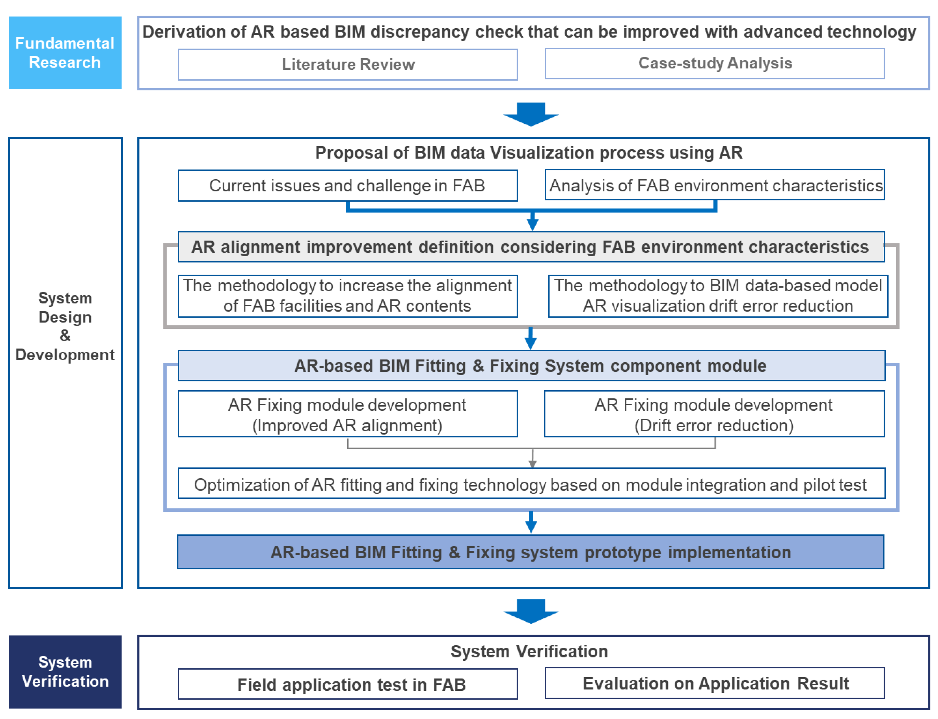
In order to support efficient and accurate operation and management throughout the FAB lifecycle that includes FAB design, construction, and maintenance, this study proposed an AR-based verification method that supports real-time compatibility verification between the target FAB facilities object and BIM data. The research procedure was as follows. First, the research trends related to BIM data verification and management using AR technology and IT-based AR compatibility were examined and analyzed through a review of preceding studies and literature. Second, common problems and needs related to AR compatibility between FAB facilities and BIM data that arise in existing FAB environments were identified through interviews with practitioners. Moreover, common causes of compatibility issues were identified based on the analysis of the FAB environment. Third, to address these issues, the AR fitting and fixing module along with the app-based system prototype were developed based on the AR compatibility improvement algorithm and system architecture built. Fourth, pilot testing was conducted to improve and optimize AR fitting and fixing module performance. Finally, the AR compatibility and validity of the AR fitting and fixing system were verified through the FAB field application. The overall research method and procedures are shown in
Figure 1 below.
3. Literature Review
3.1. Research Trends in BIM Data Verification and Management Using AR Technology
In performing the existing work processes, the need for technology to increase work efficiency by improving problems, such as increased work time and occurrence of human errors, has increased. Through intuitive transmission of information, AR technology can be effectively utilized in establishing a framework for site information transmission [
20]. Recently, research is on the rise that improves project efficiency by using AR technologies and BIM data that enable designers, engineers, managers, and other stakeholders to collaborate and share site information during the design, construction, and maintenance stages.
Moon et al. [
21] applied non-marker-based AR technology to conduct research on improving the efficiency of construction structure maintenance. Shin et al. [
22] conducted research on an AR-based underground facility management system by converting the image and property information of the BIM model to IFC format and by using Broadcast-RTK for improving location accuracy. Heo et al. [
23] used BIM architecture data to propose an architectural geometry information visualization technique that enables immersive visualization in the AR environment. Further, the authors conducted research on how to visualize the internal geometry information of a building using marker interaction and slice cut function.
Wang et al. [
24] fused BIM and AR technology to propose a facility risk assessment and management system that enables facility managers to choose maintenance policy for a single piece of equipment and to determine maintenance priorities for equipment components during the early operation and maintenance stage. May et al. [
25] proposed a BIM-based AR defect management (BIM-ARDM) system that improved inspection performance of defect management through AR visualization and eye tracking as well as head tracking data for the identification of work defect during construction inspection.
Analysis of research trends related to BIM data verification and management using AR shows an increasing trend for research on integrating BIM data and AR to enhance the efficiency and accuracy of facility management. To that end, virtual objects were projected into real facilities, visualization and interaction functions were developed, and predictive maintenance as well as disruption prevention were made possible. However, the majority of existing studies suggest that there is a need for research to improve future real-world applicability and user experience.
3.2. Research Trends in Compatibility Analysis of AR and IT Technology
During site inspection activities that commonly include quality control inspections, safety check, etc. for ongoing construction works or structures, site workers have the inconvenience of having to be familiar with several inspection information in advance, such as design, specifications, and inspection details. Additional problems associated with traditional site inspection work include the inconvenience of manually carrying inspection-related documents, errors that may occur during inspection due to handwriting of inspected items, and concerns about losing or damaging inspection worksheets. In order to solve these inefficiencies and to eliminate human errors while carrying out inspection activities, several studies have been conducted recently to propose efficient and accurate compatibility verification during site quality inspections using AR and mobile devices, such as smartphones or tablets.
Oliver et al. [
26] conducted research on three-dimensional compatibility testing based on a new two-stage depth mapping algorithm for an RGB-D camera that merges camera poses and image depths into real-time consistent 3D models. Lee et al. [
27] performed a study on accelerating the compatibility review approach using point data and AR technology to integrate real-world models and 3D design models. Pierre et al. [
28] proposed a solution that matches 3D correspondents with structures detected for anchor-plate-based pose estimation and image enlargement. Jad et al. [
29] suggested that when accuracy is of significance (i.e., less than two inches), the immersive AR can be used effectively in buildings to verify whether elements built on a more accurate but resource-intensive reality capture technology comply with BIM. Finally, Loris et al. [
30] suggested in their research the use of AR technology to detect design deviations and verified the assumption that AR tools can be effectively adopted as an alternative to the technical drawing and CAD systems, allowing users to easily detect design discrepancies between the 3D model and the corresponding physical prototype.
Analysis of AR and IT technology-based compatibility related research trends revealed that most of the existing research focuses on AR applications in conjunction with 3D models within general construction activities. However, research on enhancing the compatibility precision between physical inspection models and virtual objects, taking into account the actual site characteristics for AR application, was found to be lacking. Moreover, the direct application of this approach was known to be limited considering the characteristics of common FAB sites.
4. AR-Based Real-Time BIM Data Compatibility Testing Method for FAB Sites
4.1. Analysis of AR and BIM Data Compatibility Issues and Needs Based on Interviews with FAB Experts
In order to understand problems arising from AR-based BIM data compatibility assessment and to analyze needs that occur in the actual FAB sites, this study conducted interviews with BIM operators engaged in FAB facilities. The problems identified from the interviews were threefold: compatibility precision, compatibility range, and compatibility consistency.
In the case of compatibility precision issues, when the work was carried out through overlapping between the 3D virtual object model and the actual inspection target model using AR visualization technology, the compatibility between these two models was found to be inaccurate, creating a discrepancy error greater than 50 mm, which caused a significant reduction in work efficiency and accuracy. As for the compatibility range problems, if the marker for AR visualization of a virtual model disappeared from the smart device screen or moved beyond the set range of the marker, the virtual model disappeared, or the compatibility accuracy was significantly decreased as the point of the camera moved rapidly. Lastly, the compatibility consistency issues arise when the 3D virtual object model, while being coordinated with the inspection target model, constantly shakes without two models being fixed or deviates from the range of the inspection target model causing the drift error from the perspective of AR technology.
Table 1 below summarizes the details per the aforementioned problems as well as the analysis of needs by the involved.
As for the needs of hands-on user in regards to the compatibility precision, there was a need to ensure precision within 50 mm of AR compatibility error between the BIM-data-based 3D virtual object and the actual inspection target model. In case of the compatibility range, there was a need to maintain acceptable compatibility, even if the inspection object moved more than five meters from the reference marker or when the camera point of the device moved. As for the compatibility consistency, the 3D virtual object model, while coordinated with the inspection target model, was needed to remain consistent without continuously shaking or without deviating from the range of the target inspection model.
4.2. Analysis of FAB Site Characteristics and Identification of BIM Data Compatibility Issues
Particular characteristics pertaining to the FAB site environment were analyzed in detail to identify causes of the BIM compatibility issues, the threefold problems mentioned in
Section 4.1. Prior to the analysis of the FAB environment characteristics, common factors affecting AR compatibility were found to be as follows: (a) Sensor noise can introduce inaccuracies to sensor data, affecting compatibility. Sensor measurements with noise can inhibit accurate compatibility between virtual objects and real-world objects. (b) Sensor drift is a phenomenon in which sensor measurements gradually deviate from actual values over time, which can result in accumulated compatibility errors and cause the virtual object to deviate from its intended location. (c) Environmental interference refers to conditions, such as lack of lighting, reflective phenomena, blurring, and other environmental factors, that can interfere with sensor measurements, resulting in inaccurate compatibility. These environmental conditions can cause distortion or masquerade the key characteristics necessary for compatibility. (d) Correction errors, such as faulty sensor correction or correction drift, may introduce errors to compatibility. Inaccurate correction parameters can cause misalignments between virtual objects and coordinates of real-world objects. (e) Vision limit. AR devices are usually limited in their normal vision, capturing only a portion of real-world scenes, and this vision limitation can make it difficult to accurately integrate virtual objects with real-world objects, especially when it comes to objects outside of the vision limit. (f) Delay time refers to the delay between real scenes and corresponding virtual content, and high delay time can interfere with the coherent compatibility and make it difficult for the user to interact smoothly with virtual objects.
As a result of analyzing the FAB environmental characteristics for deriving the causes of BIM compatibility problems, sensor noise, sensor drift, and environmental interference were factors identified as causing compatibility issues.
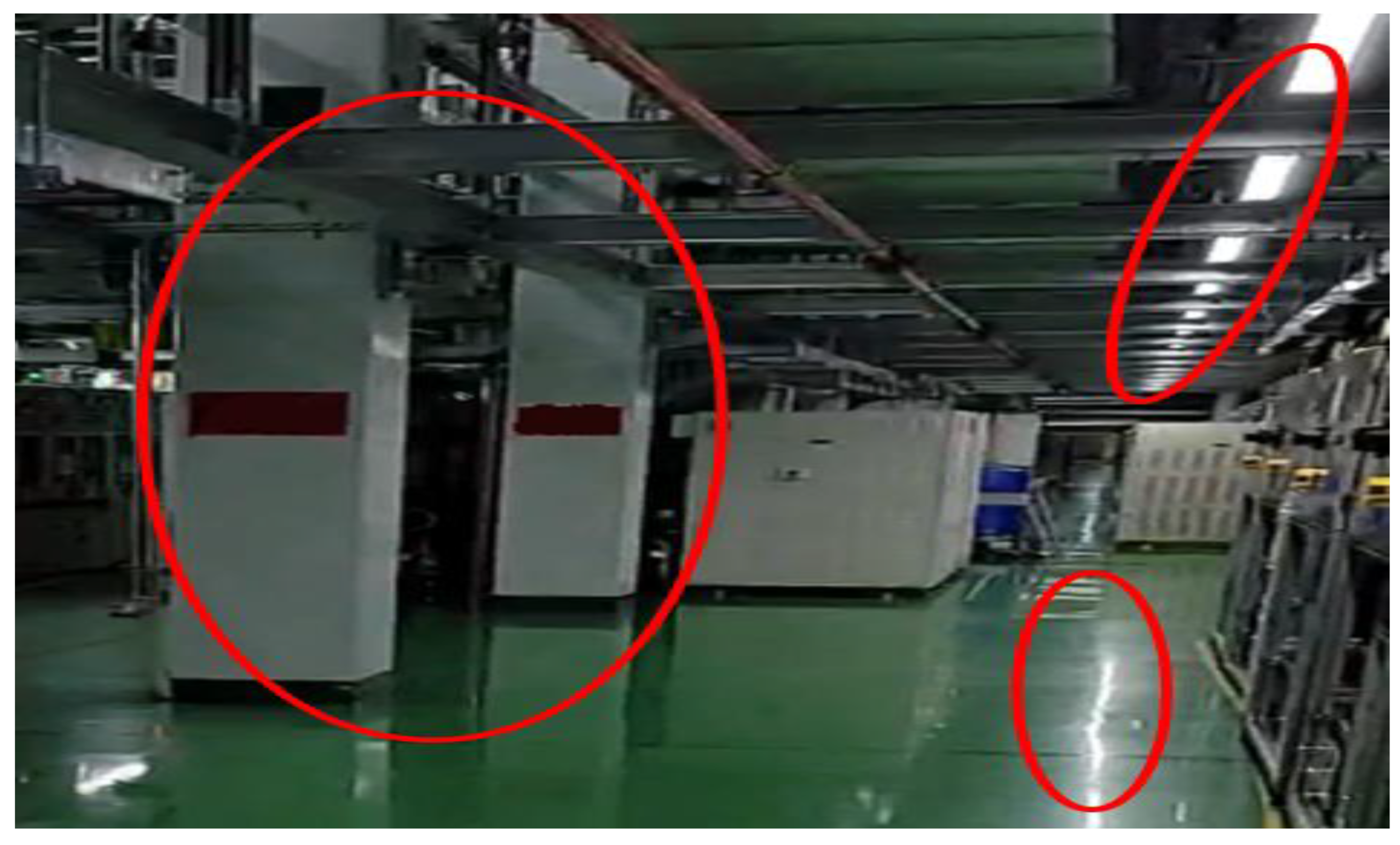
A semiconductor plant, a large-space structure that has a heavy load and a long span due to large-scale production equipment and facilities, is commonly constructed in the form of a simple square cubical as the space utilization is higher and the capacity of the equipment increases, and therefore the sales resulting from the operation of the plant can be maximized [
31]. As such, due to the structural characteristics, the interior of the FAB consists of square columns installed at regular intervals and various equipment also arranged regularly, as can be seen in
Figure 2. The AR compatibility tracking is based on the characteristics of the shape recognized by the camera where feature point identification acts as an important factor. However, in an environment with fewer changes of shape that is regular and repetitive, such as the FAB environment, a problem exists in the form of AR compatibility tracking due to the difficulty of identifying feature points for tracking. Moreover, an environment with less shape changes can lead to problems in shape distinction. Additionally, the intensive and concentrated placement of ceiling lights along with the floor painted with glossy blue urethane material result in a severe diffuse reflection in the FAB environment, making it difficult to use the application smoothly since the AR sensor camera easily loses is position or slips frequently. These FAB environment characteristics per each problem type causing compatibility issues are summarized in
Table 2.
4.3. Development Process of AR-Based Real-Time BIM Data Compatibility Verification Module
Based on the content derived through the analysis of FAB site characteristics and the needs analysis of the involved, the configuration module for an AR-based real-time BIM data compatibility verification system was developed, as shown in
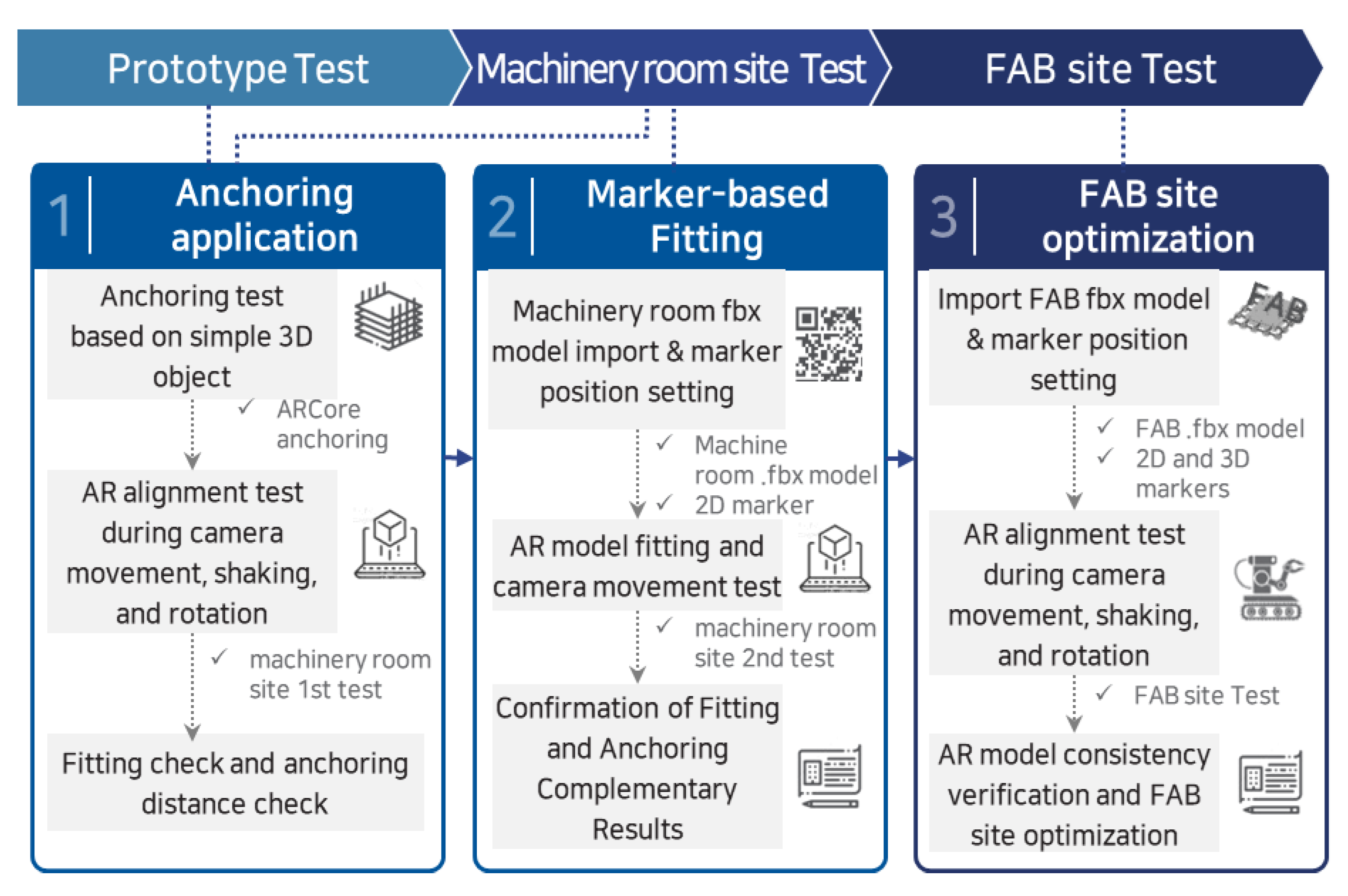
Figure 3.
The verification module was developed based on the prototype testing and functional improvement through machine room and FAB site testing, which consists of anchoring application per each testing, marker-based fitting, and FAB site optimization.
5. Development of the AR-Based Real-Time BIM Data Compatibility Verification System
5.1. Design of the AR Fitting and Fixing Application Module
For the compatibility verification system, the AR/visual SLAM fitting and fixing module was developed based on Unity along with AR Foundation using SLAM, 2D tracking, and local anchor API on ARCore. The functional requirements of the system for achieving the objectives of this study were as follows: Model loading and fitting capabilities were needed to integrate BIM-data-based AR content into real-life objects, and the study used a 2D QR marker with the width and height length of 15 cm, which can be conveniently attached and used in FAB environments. Additionally, a model fixing technology was needed to maintain the fitting of the AR model and to predict the location within the AR model according to location information recognition following the movement of camera within the FAB environment. Consequently, the study applied SLAM from ARcore, image tracking, and local anchor API through adjustment and supplementation based on the test results of FAB environment characteristics.
The development of API to implement the functional requirements of the AR fitting and fixing application system was as follows: (a) Application of SLAM from ARCore: ARCore implemented localization through the inertial measurement unit (IMU) within the device and by the space recognition of SLAM through the camera. As for the motion tracking and SLAM implementation, the local anchor of ARCore was applied, which supports local, cloud, and geospatial anchoring. Plane detection automatically adjusts the position value or anchoring while improving the motion tracking. (b) Application of ARCore image tracking: QR marker and other image markers were tested using image tracking of ARCore. Since ARCore does not support object tracking, object tracking function of Wikitude SDK or Visionlib SDK was used after adding to Unity. ARCore has its own automatic location recovery function, and such a function is subject to frequent errors due to the characteristics of the FAB environment. As such, to minimize drift error due to camera movement, AR model loading and fitting was performed through image tracking followed by the adjustment of API to allow anchoring operation through the pegging of the local anchor. Satisfying the aforementioned conditions, the AR fitting and fixing module was developed by integrating the marker and feature detection-based SLAM and anchoring function.
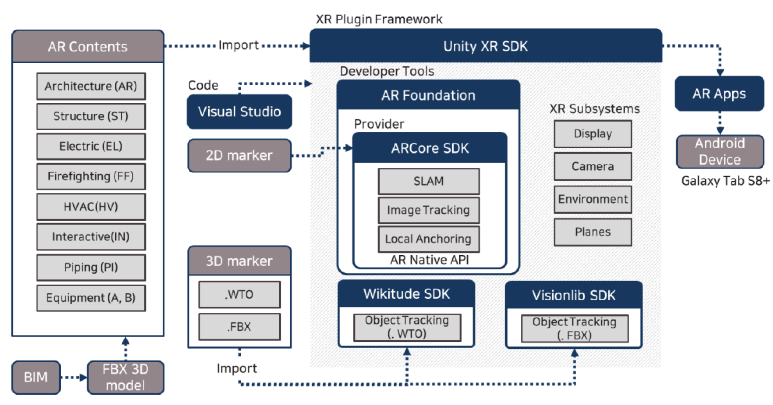
Figure 4 shows the overarching environment of the AR fitting and fixing module and AR-based real-time BIM data compatibility verification system development.
As shown in
Figure 4, the module and verification system was developed using SLAM from ARCore, image tracking, and local anchoring API based on Unity and AR Foundation. Object tracking not supported by the ARCore, which was tested using Wikitude and Visionlib, while BIM data, such as in-house machine room, FAB structure, and facilities were converted to an FBX file, which then was imported to AR contents.
The AR fitting and fixing application consists of two types of modules: a module drift-centered type A fixing module to minimize drift error and type B fitting module that enhances compatibility between a virtual object and real-life object, both using plane and feature detection anchoring and AR Core-based SLAM and motion tracking. Additionally, the application included a 3D object AR for environment analysis through indoor and outdoor environment and field testing, test through visualization field application, and function for measuring environment camera sensor recognition and error range for anchoring.
5.2. Pilot Testing for AR Fitting and Fixing
5.2.1. Prototype Tests
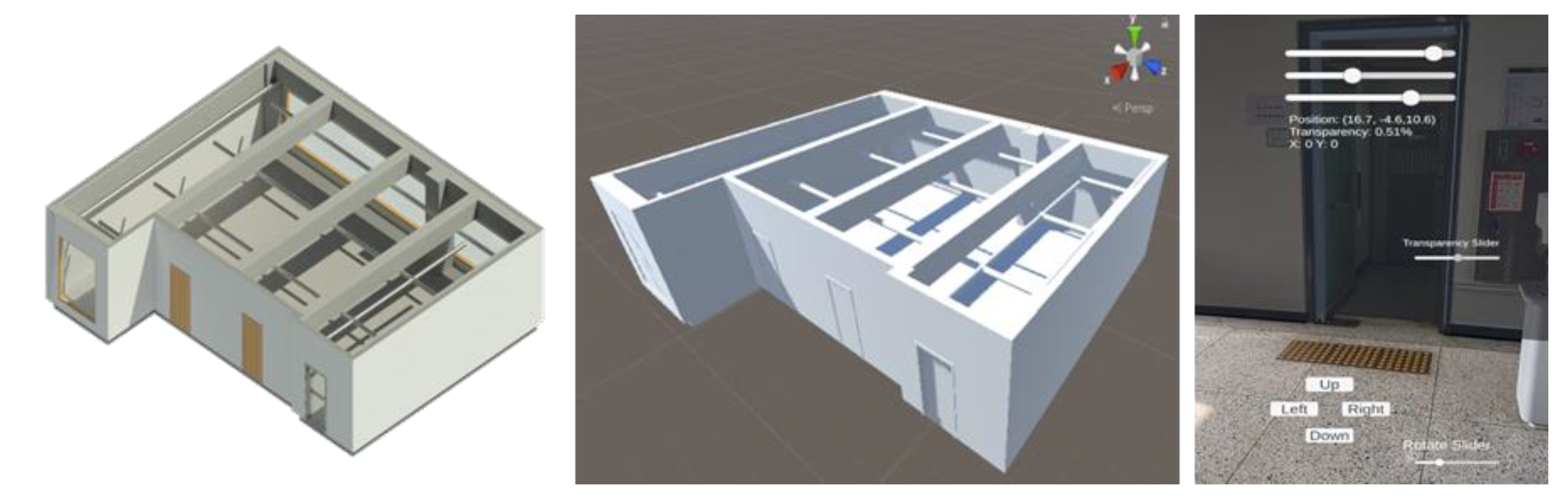
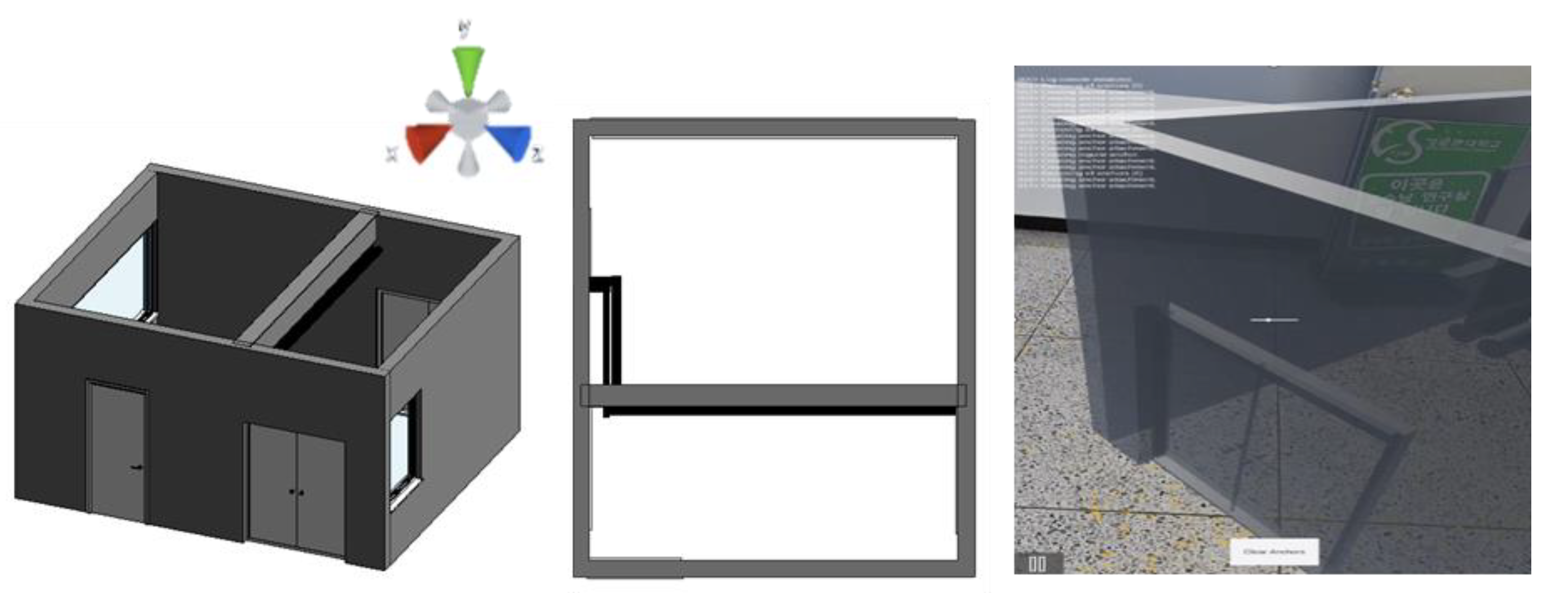
For the AR fitting and fixing module, imaging tracking and anchoring tests were carried out on Model 1 and Model 2 with a 3D object of an on and off campus gym. The compatibility result between real and virtual objects through transparency control was favorable for the AR fitting test on Model 1, whereas the AR fixing test using Model 2 resulted in a favorable anchoring condition, as movement of the AR model along with the camera movement was neglectable.
Figure 5 shows the prototype testing conducted for AR fitting using Model 1, and
Figure 6 shows the prototype testing conducted for AR fixing using Model 2.
5.2.2. Field Test on Machine Room
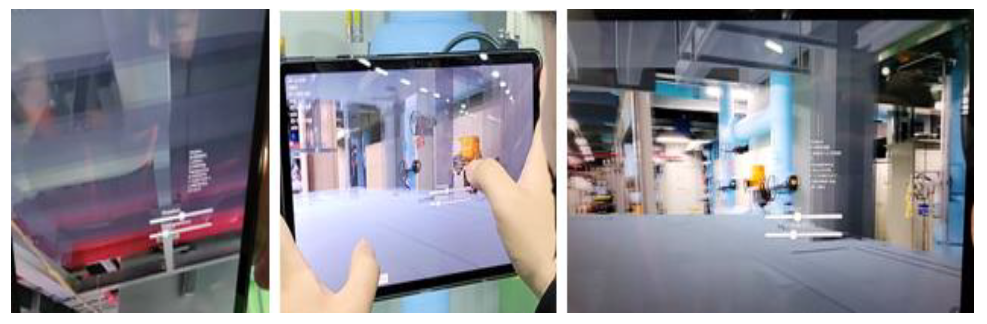
From the first round of tests on machine room for the AR fixing module, the acquisition of the compatibility coordinate for the markerless plane detection model and model drift check test was carried out (a). Although plane-detection-based drift and anchoring were favorable, accuracy was found to decline when fitting the initial AR model position (b,c). Site testing images of the first field test on the machine room for the AR fixing module are shown in
Figure 7.
During the first machine room test for the AR fitting module, a virtual maker-based anchoring test was carried out to identify site surface and influencing factors. As a result of the distance verification conducted to verify the model anchoring range within the application, the influence of the part where the upper lighting and the lighting of the floor reflected was identified. Moreover, the compatibility state of the model position generated with the reference axis of the object created in Unity (anchoring and drift of the 3D object) was found to be positive. Site testing images of the first field test on the machine room for the AR fitting module are shown in
Figure 8.
From the second round of tests on the machine room for the AR fixing module, the field arrows were set as image targets and used as references in testing the automatic compatibility of the model and visualization. As a result, the lift and anchoring were found to be favorable; however, the compatibility error occurred to some extent due to the error of the initial visualization coordinates of the AR model.
Figure 9 shows the site testing images of the second field test on the machine room for the AR fixing module.
In the second machine room test for the AR fitting module, X19 to X22 sections were targeted for testing the marker-based model compatibility as well as the virtual mark-based anchoring compatibility. Consequently, the overall axis compatibility of the model generated by the virtual marker reference axis and the actual model was analyzed to be satisfactory. Site testing images of the second field test on the machine room for the AR fitting module are shown in
Figure 10.
As for the second machine room test of the B-type application, the anchoring compatibility was tested after improving the marker axis and the object axis within the X19–X20 sections. Consequently, compatibility of the axis between the AR model and the actual object was improved, which in turn enhanced the compatibility issues between the existing BIM data-based virtual objects and real objects.
5.3. Development of the AR-Based Real-Time BIM Data Compatibility Verification
The AR-based real-time BIM data compatibility verification system presented in this study was developed according to the system concepts and process shown in
Figure 11.
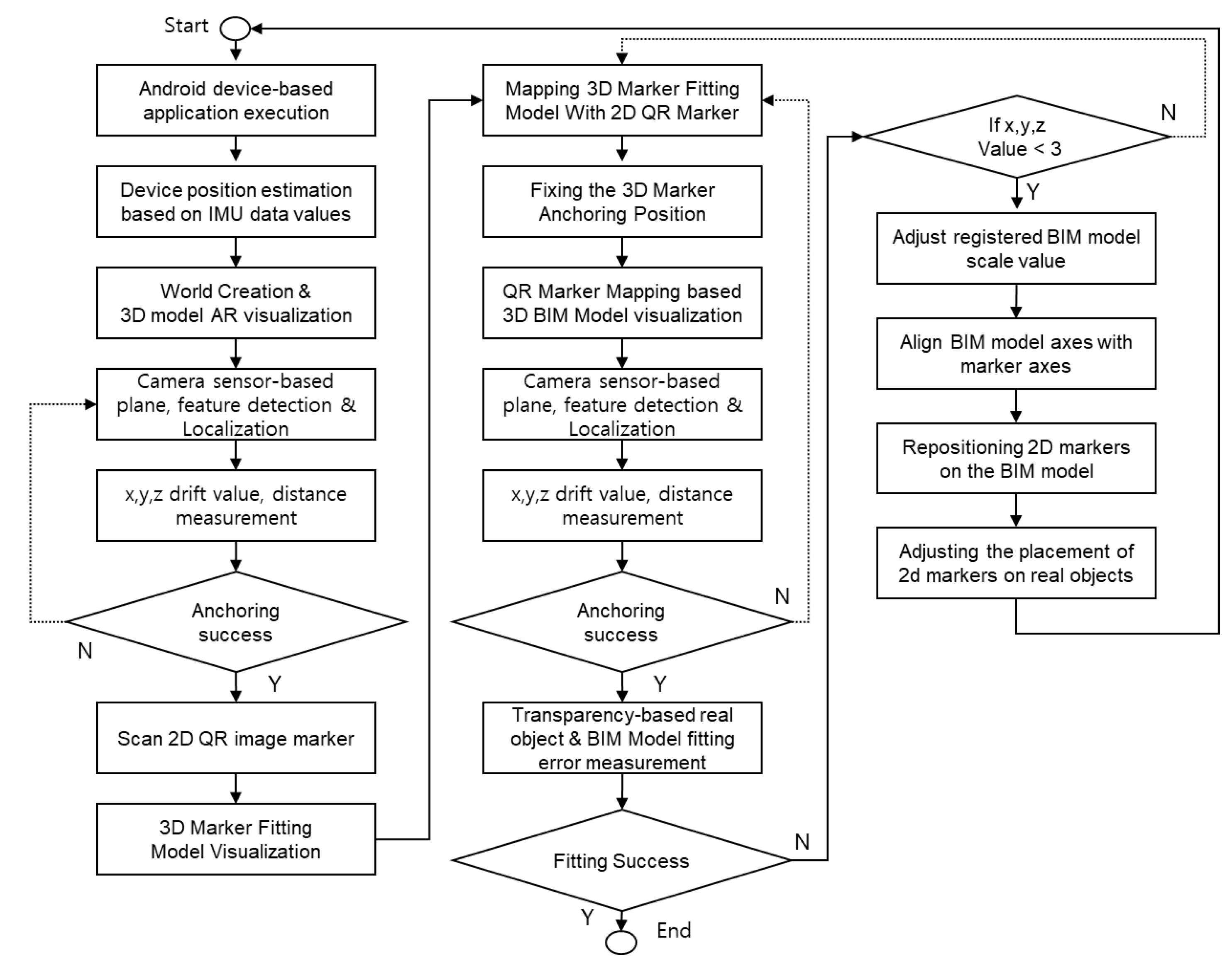
For the system development, AR technology, QR code tracking technology, SLAM technology, and anchoring technology were applied, and the development process was carried out in the following steps: (a) After running the application based on the Android device, the device location was estimated using IMU data values, and then world creation and 3D model AR visualization were activated. (b) Based on the camera sensor, device location was identified after detecting plane and characteristics, and then we measured the drift values and corresponding distance on X, Y, and Z axes according to the device movement. (c) We scanned the 2D QR image marker and visualized the 3D marker for the fitting. (d) We mapped the virtual 3D marker with 2D QR marker, fixed the 3D marker location with anchoring, and visualized the 3D BIM model based on the QR marker. (e) Using the camera sensor, the plane and characteristics of the surrounding environment were detected and the position identified; then, the drift values and corresponding distance on the X, Y, and Z axes were measured according to the movement. (f) We adjusted the transparency of the 3D BIM model and checked the fitting error with the real object. (g) We adjusted the scale value of the 3D BIM model and aligned the model axis with the marker axis to adjust the placement of real object and 2D marker.
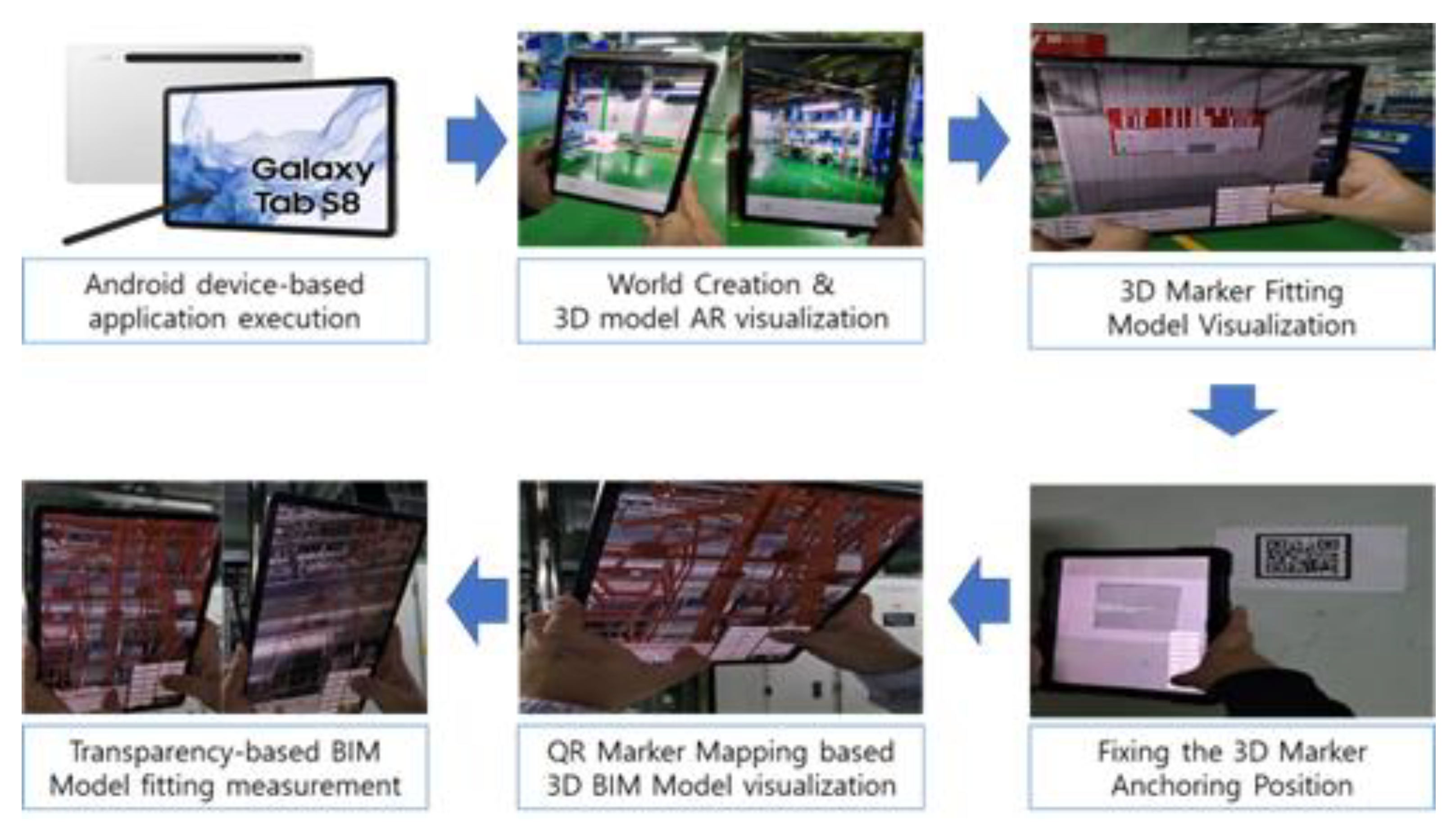
Figure 10 graphically summarizes the system development process. The hardware used for testing and implementation was a Samsung Galaxy S8, and the hardware specifications are shown in
Table 3.
The function-specific U&I and movement process of the AR-based real-time BIM data compatibility verification system is shown in
Figure 12 and consists of the following steps: (a) Implementation of localization after space recognition with SLAM technology, which utilizes RGB camera and IMU sensors. (b) Visualization of the 3D marker unto the world generated through measuring the device location. (c) Measurement of the world configuration of the current space and localization accuracy based on visualized 3D marker. (d) Scanning of the 2D QR marker using camera sensors of the device. (e) Fixing to integrate the marker and the model after visualizing the model mapped with a 2D QR marker that goes through image tracking when scanning the 2D QR maker. (f) Adjustment of the world after fixing the 3D marker location, which is achieved through automatically adjusting the position values of anchoring found from plane detection. (g) Visualization of the 3D BIM model corresponding to the 2D QR marker. (h) Correction of the errors between actual objects and BIM models.
Instead of using a real 3D marker, a virtual 3D marker was used after fixing the 3D marker location using 2D QR marker. This minimized the drifting of BIM models due to the movement of the device.
6. Field Application and Validation of the AR-Based Real-Time BIM Data Compatibility Verification System
6.1. Field Test on the FAB Site
In order to validate the AR-based real-time BIM data compatibility verification system, a field test on an actual FAB site was carried out. First, the model compatibility test and anchoring test were conducted using the object tracking function of the 3D marker based on the Wikitude SDK. The AR model was unloaded when the marker location was not recognized. Moreover, a certain amount of drifting occurred along with the camera movement, resulting in anchoring errors. In the case of the Visionlib SDK, the FAB site application test revealed that it was not suitable for a large space since it relies on the computer vision.
Consequently, to perform world configuration and localization using the 3D object and to minimize drifting of the BIM data-based virtual object that occurs due to the position change of the 2D QR marker and 3D fitting marker and finally to supplement the compatibility effective range, this study first verified whether the localization, which was based on the visualization of the 3D object, was successful or not. This verification was followed by visualizing and integrating the AR model and BIM data-based virtual object obtained through the fixing process and visualization of 3D fitting object after performing image tracking of the 2D QR marker.
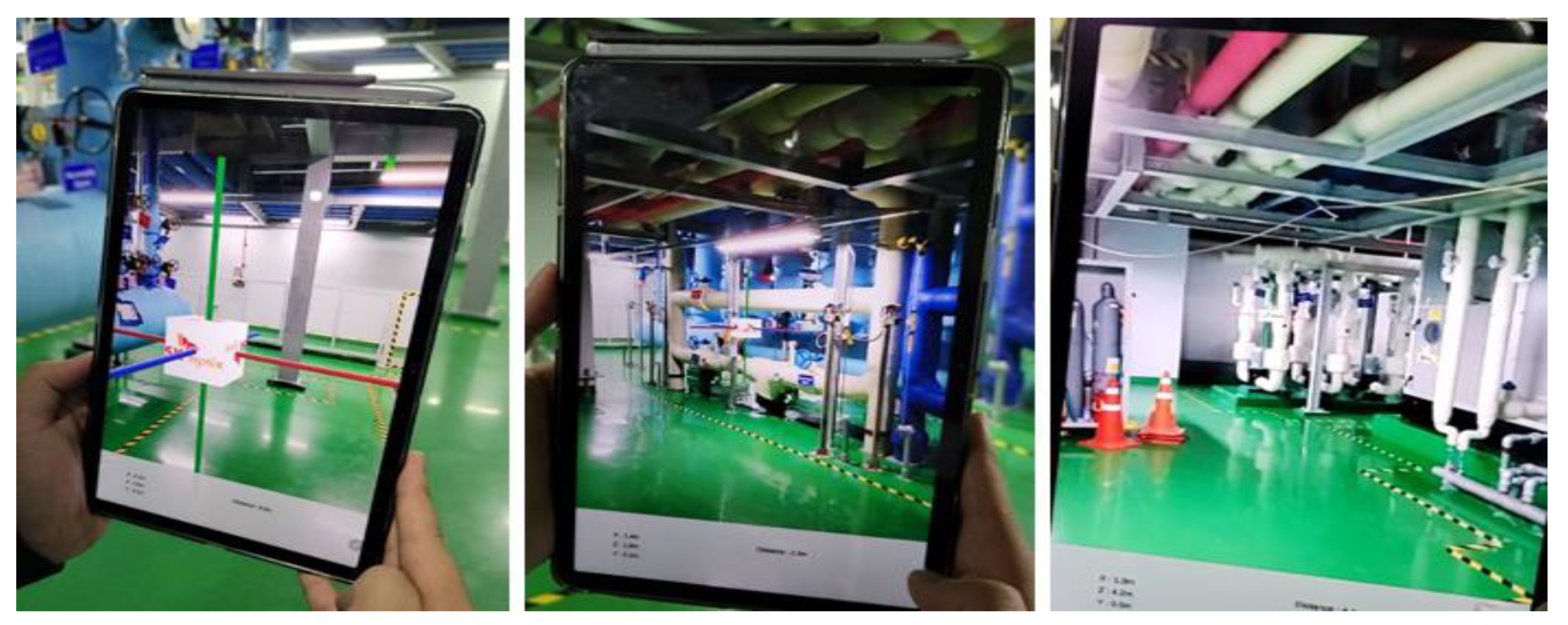
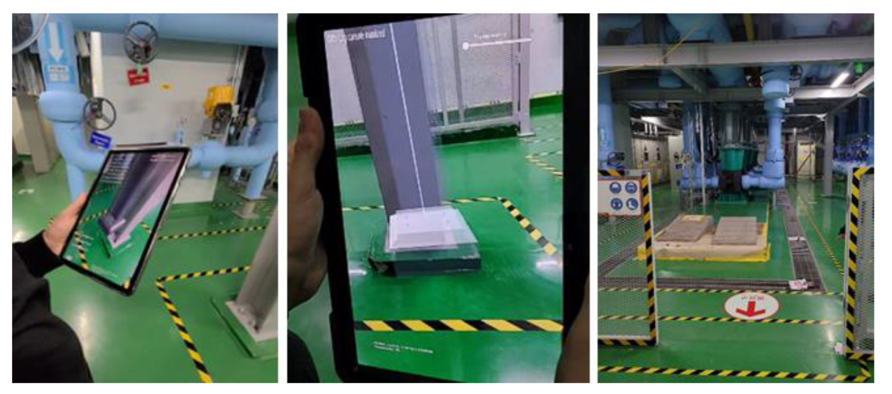
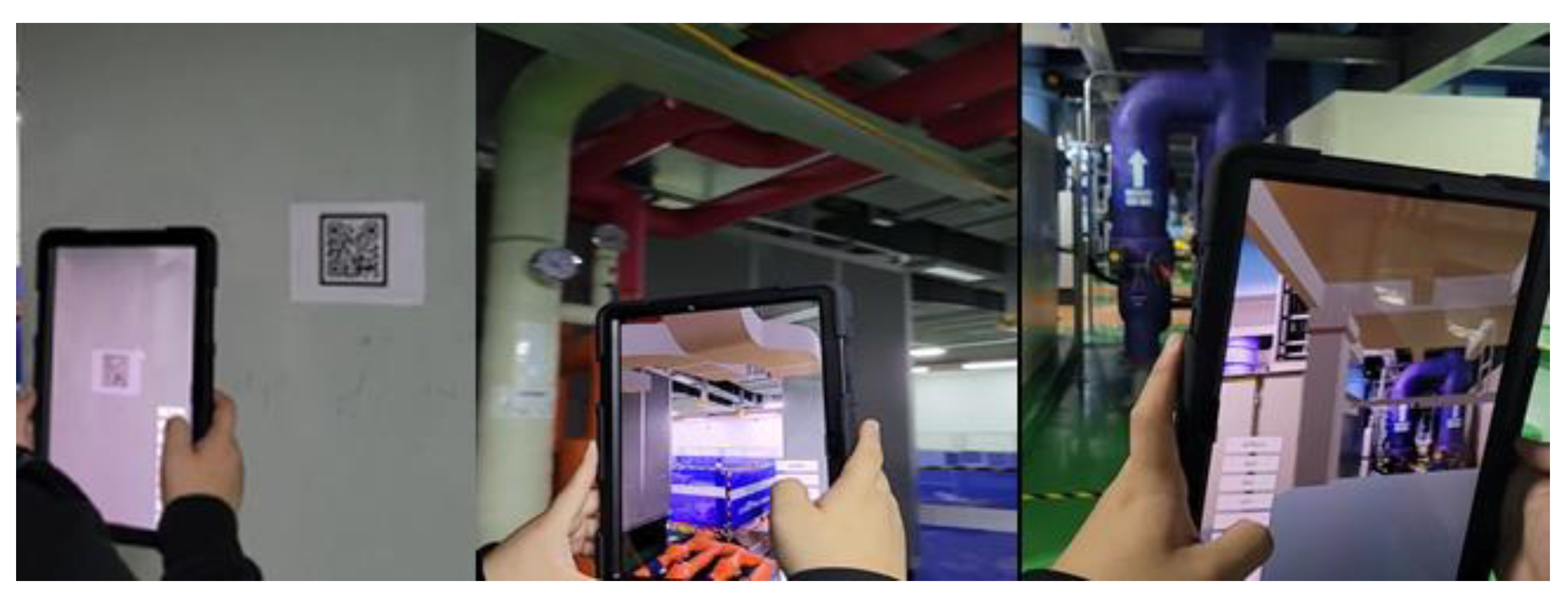
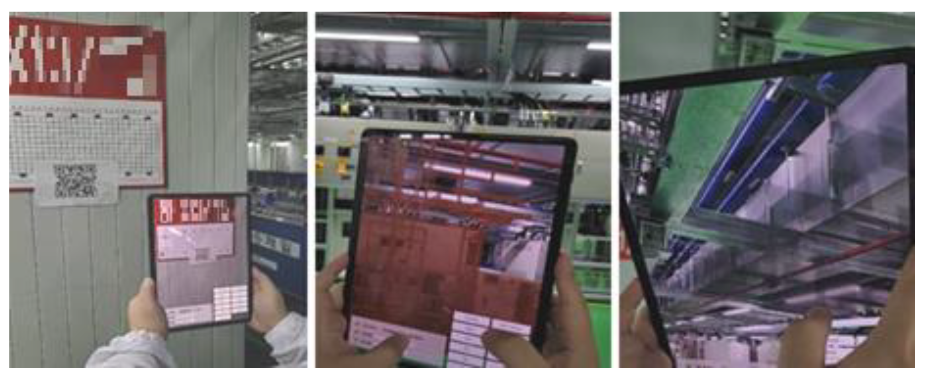
The 2D marker-based model compatibility test, feature detection, image-tracking-based world configuration, and anchoring test were conducted during the field test on the FAB site. From the two markers located within the test space radius, each confirmed favorable results in terms of the compatibility error from the initial marker location and the drift error after anchoring. Within the average radius of 6 to 15 meters from the location of two markers attached to the FAB structural columns, the device model reading showed the compatibility errors of less than 20 mm between the virtual and actual objects, drift errors of less than 15 mm on average, showing all errors within the tolerance. Furthermore, it was observed that drifting rarely occurred.
Figure 13 shows the images of the field test conducted on the actual FAB site.
6.2. Verification Results of System Field Application
In deriving verification results through system field application, when the marker moved out of the screen for machine room zones A and B and cleanroom zones A and B zones within the FAB test site, the compatibility between the AR model and the actual object was first checked, followed by the verification through marker and position coordinate test when running the application for checking the AR model compatibility according to the movement, shaking, and rotation of the camera.
For the eight space models of machine room zone A and eight space models of machine room zone B within the FAB, the fitting results according to the field test and the anchoring results for fixing were derived, as shown in the
Table 4. As a result of image tracking using QR markers, the initial load and fitting errors of the AR model were found to be very favorable, as errors were within 10 mm based on the marker. Local anchoring results were also very satisfactory when the camera moved, shook, and rotated, as well as when the marker disappeared from the screen. The model compatibility and anchoring results were satisfactory, with an average compatibility error within 20 mm and drift error within 15 mm being measured from the initial model fitting position to within maximum 12 m and an average radius of six meters.
From the FAB site, eight space models and one equipment model from zone A and eight space models and one equipment model from zone B of cleanroom were targeted for the field test. The verification results encompassing the fitting result and anchoring result for the fixing were found, as shown in
Table 5. As a result of image tracking using a QR marker, the initial loading of the AR model and fitting errors were found to be very favorable as errors were within 10 mm based on marker. Local anchoring results were also very satisfactory when the camera moved, shook, and rotated, as well as when the marker disappeared from the screen. The model compatibility and anchoring results were satisfactory with an average compatibility error of space model within 20 mm, equipment model compatibility error with 15 mm, and drift error within 15 mm, all measured from the initial model fitting position to within maximum 15 m and an average radius of eight meters.
7. Conclusions and Future Research
This study proposed an AR-based real-time BIM data compatibility verification method for FAB digital twin implementation, as well as demonstrating that it could be converted into a system and applied to actual FAB sites. As a result of the development and verification of this system, the proposed AR-based real-time BIM data compatibility verification system enables the accurate fitting of the AR model and actual object through AR tracking and anchoring technology considering the characteristics of FAB sites. After the fitting, the system was able to maintain compatibility, even when the camera moved and the marker moved away from the screen. By expanding the effective distance of compatibility between the AR model and the actual object, it was possible to increase the AR application range between the 3D virtual object model and the test target model and to improve the compatibility.
In order to construct the system proposed in this study and to enable field application, interviews were conducted with FAB experts and AR compatibility issues between BIM data and FAB facilities generated in the existing FAB environment, and the needs of the involved were identified. Moreover, the causes of compatibility problems were identified through FAB environment analysis. Considering the identified needs and FAB environment factors for compatibility problems, the AR compatibility improvement algorithm and system architecture pertaining to the FAB environment were established, and the AR fitting and fixing module along with the app-based system prototype were developed. In addition, through an AR compatibility test based on an FAB field application of the AR fitting and fixing system and through optimization, an AR-based real-time BIM data compatibility verification system was developed. Instead of using an actual 3D marker, a virtual 3D object-based localization was verified after fixing the 3D marker location using a 2D QR marker. This minimized the drifting of BIM models due to the movement of the device.
Based on the results of the study, to support efficient and precise work and management throughout the FAB life cycle, including FAB design, construction, and maintenance, it can be decided that real-time compatibility verification between the FAB facilities subject to verification and the BIM model can be supported while BIM data analysis and utilization are deemed possible. In the future, research is needed to measure the current state, detect risk in advance, and optimize the operation process by using virtual FAB facility and equipment data connected to real life.
Author Contributions
Conceptualization, J.S. and S.P.; methodology, J.S., S.P. and S.K.; software, J.S. and J.B.; validation, J.S. and C.-S.C.; formal analysis, J.S. and S.C.; investigation, J.S. and K.L.; resources, J.S., S.P., and J.B.; data curation, J.S. and K.L.; writing—original draft preparation, J.S.; writing—review and editing, S.K. and C.-S.C.; visualization, J.S.; supervision, S.K. and C.-S.C.; project administration, S.K.; funding acquisition, S.K. All authors have read and agreed to the published version of the manuscript.
Funding
This research was conducted with the support of the “National R&D Project for Smart Construction Technology (23SMIP-A158708-04)” funded by the Korea Agency for Infrastructure Technology Advancement under the Ministry of Land, Infrastructure and Transport, and managed by the Korea Expressway Corporation.
Data Availability Statement
Not applicable.
Acknowledgments
The authors thank SK Hynix and the BIM 5D technical team for their support, including valuable assistance in providing the test environment and cooperating with interviews.
Conflicts of Interest
The authors declare no conflict of interest.
References
- Cha, M.S.; Jang, J.S. Effective Operation of SPC System in Semiconductor Manufacturing. J. Korean Inst. Plant Eng. 2009, 14, 95–103. [Google Scholar]
- Kwon, O.; Jo, C.-W. Proposal of BIM Quality Management Standard by Analyzing Domestic and International BIM Guides. J. Korea Inst. Build. Constr. 2011, 11, 265–275. [Google Scholar] [CrossRef]
- Kang, T.W.; Hong, C.H. GIS-based BIM Object Visualization System Architecture Design using Open source BIM Server Cost-Effectively. J. Korea Spat. Inf. Soc. 2014, 22, 45–53. [Google Scholar]
- Yoon, S.-W.; Kim, S.-A.; Choi, J.-M.; Keum, D.-Y.; Jo, C.-W. A Proposal for Using BIM Model Created in Design to Construction Phase—Case Study on preconstruction adopting BIM. J. KIBIM 2015, 5, 1–10. [Google Scholar] [CrossRef]
- Jo, Y.-H.; Lee, J.-S.; Ham, N.-H.; Kim, J.-J. Bim Strategy Plan through Domestic Construction Companies BIM Project Case Analysis—Focused on the BIM USE of the project from 2009 to 2015. J. KIBIM 2016, 6, 1–11. [Google Scholar] [CrossRef]
- Huang, Z. Application research on BIM+AR technology in construction safety management. J. Phys. Conf. Ser. 2020, 1648, 042019. [Google Scholar] [CrossRef]
- Chen, H.; Hou, L.; Zhang, G.; Moon, S. Development of BIM, IoT and AR/VR technologies for fire safety and upskilling. Autom. Constr. 2021, 125, 103631. [Google Scholar] [CrossRef]
- Mehrdad, M.; De Gaetani, C.I.; Migliaccio, F. A web-based BIM–AR quality management system for structural elements. Appl. Sci. 2019, 9, 3984. [Google Scholar]
- Julia, R.; Riedl, M.; Matt, D.T. BIM-based and AR application combined with location-based management system for the improvement of the construction performance. Buildings 2019, 9, 118. [Google Scholar]
- Adeeb, S.; Dinis, F.M.; Duarte, J.; Sanhudo, L.; Calvetti, D.; Baptista, J.S.; Martins, J.P.; Soeiro, A. Recent tools and techniques of BIM-Based Augmented Reality: A systematic review. J. Build. Eng. 2021, 42, 102500. [Google Scholar]
- Lee, S.-W.; Lee, K.-S.; Choi, S.-I.; Ryu, S.-C.; Park, J.-S. AR system for FAB construction management using BIM data under fast track condition. J. KIBIM 2022, 12, 1–18. [Google Scholar]
- Lee, J.-G.; Choi, M.-J.; Lim, Y.-J.; Seo, J.-O. Comparative Analysis of Visual Presentation and User Acceptability of Virtual/Augmented Reality Application for Architectural Design Review. J. KIBIM 2019, 9, 1–9. [Google Scholar]
- Zhang, J.-S.; Zhao, L.-H.; Cui, Y.-H.; Ren, G.-Q.; Li, H.-J. Code compliance checking of structural design based on BIM model. J. Graph. 2021, 42, 133. [Google Scholar]
- Meng, S.; Yang, B.; Wang, X. Research on integrated design of modular steel structure container buildings based on BIM. Adv. Civ. Eng. 2022, 2022, 4574676. [Google Scholar]
- Chen, H.-M.; Huang, P.-H. 3D AR-based modeling for discrete-event simulation of transport operations in construction. Autom. Constr. 2013, 33, 123–136. [Google Scholar] [CrossRef]
- Kim, H.; Kang, L. Development of Pre-construction Verification System using AR-based Drawings Object. LHI J. Land Hous. Urban Aff. 2020, 11, 93–101. [Google Scholar]
- Mohammad, R.; Fan, M.; Yu, C. Advanced visualization and simulation techniques for modern construction management. Indoor Built Environ. 2014, 23, 665–674. [Google Scholar]
- Li, X.; Yi, W.; Chi, H.-L.; Wang, X.; Chan, A.P.C. A critical review of virtual and augmented reality (VR/AR) applications in construction safety. Autom. Constr. 2018, 86, 150–162. [Google Scholar] [CrossRef]
- James, G.; Hartley, T.; Heesom, D. A multi-user collaborative BIM-AR system to support design and construction. Autom. Constr. 2021, 122, 103487. [Google Scholar]
- Schiavi, B.; Havard, V.; Beddiar, K.; Baudry, D. BIM data flow architecture with AR/VR technologies: Use cases in architecture, engineering and construction. Autom. Constr. 2022, 134, 104054. [Google Scholar] [CrossRef]
- Moon, S.Y.; Yun, S.Y.; Kim, H.; Kang, L. Improved Method for Increasing Maintenance Efficiency of Construction Structure Using Augmented Reality by Marker-Less Method. KSCE J. Civ. Environ. Eng. Res. 2015, 35, 961–968. [Google Scholar]
- Shin, J.; An, S.; Song, J. Development of an augmented reality based underground facility management system using BIM information. J. Korean Tunn. Undergr. Space Assoc. 2022, 24, 525–538. [Google Scholar]
- Heo, K.-J.; Lee, S.-J.; Jung, S.-K. A Study of Augmented Reality based Visualization using Shape Information of Building Information Modeling. J. Korea Spat. Inf. Society 2012, 20, 1–11. [Google Scholar]
- Wang, T.-K.; Piao, Y. Development of BIM-AR-based facility risk assessment and maintenance system. J. Perform. Constr. Facil. 2019, 33, 04019068. [Google Scholar] [CrossRef]
- May, K.W.; KC, C.; Ochoa, J.J.; Gu, N.; Walsh, J.; Smith, R.T.; Thomas, B.H. The Identification, Development, and Evaluation of BIM-ARDM: A BIM-Based AR Defect Management System for Construction Inspections. Buildings 2022, 12, 140. [Google Scholar] [CrossRef]
- Oliver, W.; Meyer, M.; Stricker, D. Augmented reality 3d discrepancy check in industrial applications. In Proceedings of the 2016 IEEE International Symposium on Mixed and Augmented Reality (ISMAR), Merida, Mexico, 19–23 September 2016; IEEE: Piscataway, NJ, USA, 2016. [Google Scholar]
- Lee, J.; Lee, H.; Kim, D.; Li, R. Point Cloud Data based Augmented Reality for Rapid Discrepancy Check. In Proceedings of the Korean CDE Society Conference, Pyeongchang, Republic of Korea, 12–14 February 2014; pp. 225–228. [Google Scholar]
- Georgel, P.; Schroeder, P.; Benhimane, S.; Hinterstoisser, S.; Appel, M.; Navab, N. An industrial augmented reality solution for discrepancy check. In Proceedings of the 2007 6th IEEE and ACM International Symposium on Mixed and Augmented Reality, Nara, Japan, 13–16 November 2007; IEEE: Piscataway, NJ, USA, 2007. [Google Scholar]
- Jad, C.; Ayer, S.K.; McCord, K.H. Augmented reality to enable users to identify deviations for model reconciliation. Buildings 2021, 11, 77. [Google Scholar]
- Loris, B.; Marino, E. An augmented reality tool to detect design discrepancies: A comparison test with traditional methods. In Augmented Reality, Virtual Reality, and Computer Graphics, Proceedings of the 6th International Conference, AVR 2019, Santa Maria al Bagno, Italy, 24–27 June 2019; Proceedings, Part II 6; Springer International Publishing: Cham, Switzerland, 2019. [Google Scholar]
- Choi, I.; Choi, S.; Kim, K.; Joo, H.; Kwon, S.; Park, K. Unit Combined Precast Composite Beam System Developed for Construction of Semiconductor Factory. J. Soc. Concr. Stud. 2016, 28, 36–40. [Google Scholar]
Figure 1.
Research methods and procedures.
Figure 1.
Research methods and procedures.
Figure 2.
Example of FAB environmental characteristic factor affecting compatibility.
Figure 2.
Example of FAB environmental characteristic factor affecting compatibility.
Figure 3.
Development process of the configuration module for the BIM data compatibility verification system.
Figure 3.
Development process of the configuration module for the BIM data compatibility verification system.
Figure 4.
Development environment of the XR fitting and fixing module and XR-based real-time BIM data compatibility verification system.
Figure 4.
Development environment of the XR fitting and fixing module and XR-based real-time BIM data compatibility verification system.
Figure 5.
Prototype tests for the AR fitting Model 1.
Figure 5.
Prototype tests for the AR fitting Model 1.
Figure 6.
Prototype tests for the AR fitting fixing Model 2.
Figure 6.
Prototype tests for the AR fitting fixing Model 2.
Figure 7.
Images of the first field test on the machine room for the AR fixing module.
Figure 7.
Images of the first field test on the machine room for the AR fixing module.
Figure 8.
Images of the first field test on the machine room for the AR fitting module.
Figure 8.
Images of the first field test on the machine room for the AR fitting module.
Figure 9.
Images of the second field test on the machine room for the AR fixing module.
Figure 9.
Images of the second field test on the machine room for the AR fixing module.
Figure 10.
Images of the second field test on the machine room for the AR fitting module.
Figure 10.
Images of the second field test on the machine room for the AR fitting module.
Figure 11.
Development process of BIM data compatibility verification.
Figure 11.
Development process of BIM data compatibility verification.
Figure 12.
Field application process of the BIM data compatibility verification system.
Figure 12.
Field application process of the BIM data compatibility verification system.
Figure 13.
Images of the field test conducted on the FAB site.
Figure 13.
Images of the field test conducted on the FAB site.
Table 1.
Problem-specific details and related users’ needs analysis.
Table 1.
Problem-specific details and related users’ needs analysis.
| Problem Type | Details | Related Needs |
|---|
| Compatibility precision | AR compatibility between the BIM-data-based 3D virtual object model and the actual test target model was less precise (error of roughly 50 mm or greater) | Secure AR compatibility precision of less than 50 mm between BIM data-based 3D virtual object and actual test target model |
| Compatibility range | When moving beyond a certain radius (about 2 m) based on the marker or when the viewpoint of camera moves quickly, the virtual model disappears, or the compatibility rate decreases significantly | Maintain model compatibility even when moving more than 5 m or when the viewpoint of camera moves |
| Compatibility consistency | Drift error occurs when the 3D virtual object model constantly shakes without being fixed or deviates from the range of the inspection target model, after both models being coordinated | The 3D virtual object model should remain consistent without continuously shaking or without deviating from the target inspection model range |
Table 2.
Analysis of FAB environment characteristics by problem type and identification of causes.
Table 2.
Analysis of FAB environment characteristics by problem type and identification of causes.
| Problem Type | FAB Environment Characteristics | Compatibility Influencing Factors |
|---|
| Compatibility precision | A square cube-shaped environment in which the arrangement of facilities and columns is regular with repetitive and little repetitive shape change | Environment interference |
| Compatibility range | Intensive arrangement of lighting and the floor painted with blue urethane material creates an environment with severe diffuse reflection due to its unique gloss | Sensor noise, sensor drift |
| Compatibility consistency | Intensive arrangement of lighting and the floor painted with blue urethane material creates an environment with severe diffuse reflection due to its unique gloss | Sensor noise, sensor drift |
Table 3.
Specifications of the hardware used for implementation.
Table 3.
Specifications of the hardware used for implementation.
| | Specifications |
|---|
| Model | Samsung Galaxy Tab S8 |
| CPU | Qualcomm Snapdragon 8 Gen 1 (4 nm) Octa-core (1 × 3.00 GHz Cortex-X2 & 3 × 2.50 GHz Cortex-A710 & 4 × 1.80 GHz Cortex-A510) |
| GPU | Qualcomm Adreno 730 (818 MHz) |
| RAM | 12 GB |
| STORAGE | 512 GB |
| REAR CAMERA | 13 MP, f/2.0, 26 mm (wide), 1/3.4”, 1.0 µm, AF6 MP, f/2.2, (ultrawide) LED flash, HDR, panorama 4K@30/60 fps, 1080p@30 fps |
Table 4.
FAB machine room field application test and verification results.
Table 4.
FAB machine room field application test and verification results.
| | FAB Machine Room Zone A Test | FAB Machine Room Zone B Test |
|---|
| Test image | ![Buildings 13 02683 i001]() | ![Buildings 13 02683 i002]() |
| Fitting results | The average compatibility error between the actual object and the BIM-data-based AR model for the eight spatial models in zone A of the machine room was 16 mm, showing favorable fitting compatibility | The average compatibility error between the actual object and the BIM-data-based AR model for the eight spatial models in zone B of the machine room was 17 mm, showing favorable fitting compatibility |
| Anchoring results | After 6 m of the camera movement, the 3D object’s X, Y, and Z axes movement distance from the initial position was within 12 mm and the drift error within 12 mm, showing a satisfactory anchoring result | After 12 m of the camera movement, the 3D object’s X, Y, and Z axes movement distance from the initial position was within 15 mm and the drift error within 15 mm, showing a satisfactory anchoring result |
Table 5.
FAB cleanroom field application test and verification results.
Table 5.
FAB cleanroom field application test and verification results.
| | FAB Cleanroom Zone A Field Test | FAB Cleanroom Zone B Field Test |
|---|
| Test image | ![Buildings 13 02683 i003]() | ![Buildings 13 02683 i004]() |
| Fitting results | For 8 space models and 1 equipment model in FAB zone A, the average compatibility error between the real object and the BIM data-based AR model was within 18 mm on average for the space model and within 15 mm for the equipment model, resulting in a favorable fitting compatibility | For 8 space models and 1 equipment model in FAB zone B, the average compatibility error between the real object and the BIM data-based AR model was within 19 mm on average for the space model and within 14 mm for the equipment model, resulting in a favorable fitting compatibility |
| Anchoring results | Test result for shaking, rotating, and moving the camera about 8 m from the marker, the anchoring condition of the AR model, was found to be favorable, and the average drift error was confirmed to be within 13 mm | Test result for shaking, rotating, and moving the camera about 15 m from the marker, as well as measuring from the opposite view of equipment, showed the anchoring condition of the AR model to be favorable, and the average drift error was confirmed to be within 15 mm |
| Disclaimer/Publisher’s Note: The statements, opinions and data contained in all publications are solely those of the individual author(s) and contributor(s) and not of MDPI and/or the editor(s). MDPI and/or the editor(s) disclaim responsibility for any injury to people or property resulting from any ideas, methods, instructions or products referred to in the content. |
© 2023 by the authors. Licensee MDPI, Basel, Switzerland. This article is an open access article distributed under the terms and conditions of the Creative Commons Attribution (CC BY) license (https://creativecommons.org/licenses/by/4.0/).

 ,
, 


