Article

Experimental Study on Bearing Behavior and Soil Squeezing of Jacked Pile in Stiff Clay

1
Anhui Province Key Laboratory of Green Building and Assembly Construction, Anhui Institute of Building Research & Design, Hefei 230031, China
2
School of Civil Engineering, Hefei University of Technology, Hefei 230009, China
*
Author to whom correspondence should be addressed.
Buildings 2023, 13(10), 2609; https://doi.org/10.3390/buildings13102609
Submission received: 4 September 2023 / Revised: 25 September 2023 / Accepted: 29 September 2023 / Published: 16 October 2023
(This article belongs to the Special Issue Building Vibration and Soil Dynamics)

Abstract

:
In order to study the bearing behavior and soil-squeezing of jacked piles in stiff clay, two groups of pile penetration tests were performed, with a rough pile that can reproduce the quick-shear behavior of the pile–soil interface, i.e., group 1 in stiffer clay, and group 2 in softer clay for comparison. For each group, the adjacent pile was additionally penetrated at different pile spacings to study the soil-squeezing effect on an adjacent pile. The results show that the penetration resistance increased rapidly at the beginning and then increased at a lower rate. This is because the resistance at the pile end increased rapidly at the beginning and then kept stable with fluctuations, whereas the resistance at the pile side continually increased due to the increasing contact area. Therefore, the ratio of the resistance at the pile end to the total penetration resistance exhibited a softening behavior, which first increased to a peak and then gradually decreased. In addition, there was soil-squeezing stress and soil-squeezing displacement in the ground and adjacent piles due to pile penetration. In stiffer clay, the soil-squeezing stress was larger than that in softer clay due to the higher strength, whereas the soil-squeezing displacement was smaller than that in softer clay due to the low compressibility. In addition, the nonlinear equation form y = ae−bx can be employed to describe the effect of pile spacing on the vertical flotation, horizontal deviation, and pile strain of the adjacent pile.

1. Introduction

Jacked piles have been widely employed in civil engineering due to the advantages of low cost, strong quality controllability, fast construction speed, and convenient quality testing [1,2,3,4]. In the design and construction of jacked piles, the soil-squeezing effect is essential to prevent engineering accidents such as pile breakage and pile floating [5,6,7].
Great efforts have been made to study the soil-squeezing effect during pile penetration by theoretical methods [8,9,10], numerical simulations [11,12,13,14], field tests [15,16,17], and indoor model tests [18,19,20,21,22]. The theoretical methods, e.g., cavity expansion theory [23], can be employed to predict the soil displacement and ground deformations for jacked pile penetration, but the pile–soil frictional behavior is ignored and more reliable experimental data are necessary for validation. The numerical simulation can provide a unique view of the soil deformation and stress evolution, but large soil deformation and soil failure appear during jacked pile penetration, which can hardly be well simulated by the finite element method [24,25]. The discrete element method, which can capture the soil’s large deformation and failure process well, is limited by its huge computation cost [14,26,27], especially when the water effect and unique particle shape should be taken into consideration for clays [28,29]. The field test can provide the most reliable data about the soil-squeezing effect but is limited by its huge cost and complex geological conditions [15,30]. In recent decades, the physical model test has been quite popular in investigating the bearing behavior and soil-squeezing effect. With a focus on the penetration resistance of jacked piles, previous research has investigated the effects of time [31], soil plugging [32], friction fatigue [33], the pile-bearing layer [34], pile diameters [16], etc. With a focus on the soil-squeezing effect, various test methods and techniques have been employed, including the half-model test [35,36], X-ray radiography tomography [32]), computed tomography (CT) [19], and transparent soils [37,38,39], which are quite expensive when applied to monitoring soil deformation.
However, most indoor model tests of jacked piles focus on the penetration resistance and soil-squeezing effect in sands [33,35,40] and soft clays [30,34] with restively low shear strength. Little attention has been paid to those in stiffer clays with low compressibility and high shear strength, especially the soil-squeezing effect on the adjacent pile in stiffer clay. As a result, the design method and experimental findings on sands and soft clays can hardly be applied to the analysis of the soil–pile interaction in stiffer clays of Central China, which constitutes the main motivation for this paper.
In addition, the piles in most experimental tests are usually smooth, simulated by aluminum piles [6,19,34], steel piles [31,33,40], polymethyl methacrylate piles [27], etc., which cannot capture the quick-shear behavior between concrete piles and soil. Therefore, a rough pile, which can reproduce the quick-shear behavior between a concrete pile and stiffer clay, was employed here to study the penetration resistance and soil-squeezing effect in stiffer and softer clays. After briefly introducing the stiffer clay and rough pile, the closed-end rough piles were penetrated into softer and stiffer clays to analyze the penetration resistance and soil-squeezing effect. After this, the adjacent pile was penetrated at different pile spacings, focusing on the soil-squeezing effect on the adjacent pile. The experimental data can provide advice for better designing and constructing jacked piles in stiffer clay areas of Central China.

2. Model Setup

2.1. Experimental Apparatus

Figure 1 provides the experimental apparatus used in the test, including the soil bin, bracket, two railways, and penetration system. The soil bin was carefully designed and manufactured to remove the boundary effects on experimental results. Gui et al. [41] stated that the boundary effect was neglectable when the distance between the penetration point and the side boundary wall was 10 times larger than the cone diameter. Here, the pile diameter D was scaled to be 40 mm in the test, and the square soil bin was designed to be 1.0 m in side length L. Thus, the ratio of the soil bin side length to the pile diameter was 25, which is larger than suggested in previous research [16,41,42], and the boundary effect can be ignored. The bracket (i.e., 400 mm in height) is employed to provide enough space to allow a stable penetration resistance to occur. The railways can move freely on the bracket and the penetration system can freely move on the railways, allowing the pile to penetrate at different positions. The penetration system consists of the motor and shaft. The pile can be fixed on the shaft and forced into the stiffer clay by the motor with a velocity ranging from 0.2 to 2.0 mm/s.

2.2. Test Material

In China, stiffer clay is generally distributed in the middle areas (e.g., Anhui province), whereas softer clay is generally distributed in the east–south areas (e.g., Shanghai City and Guangdong province), where jacked piles were first widely employed in civil engineering. As a result, the abundant engineering experience and design method for softer clays leads to frequent engineering accidents in stiffer clay, e.g., pile breakage and pile floating [43]. Thus, two clays were employed here to perform a pile penetration test, one simulating natural stiff clay with high strength and low compressibility and the other simulating soft and saturated clay, aiming to show the difference in the penetration resistance and soil-squeezing effect of jacked piles. The stiffer clay in Hefei, Anhui province, was employed to prepare these two clays. In light of the remolded clay exhibiting a lower strength and higher compressibility than the natural stiff clay, the remolded clay treated with 1% chunam in mass was employed to reproduce the mechanical and compressive behavior of natural stiff clay here. Note that a similar technique has been employed to mimic the structure effect of natural clay [21,44]. Figure 2 presents the relationships between the deviatoric stress and the axial strain of the stiffer and softer clays employed in the test. Figure 2 shows that the stiffer clay (i.e., remolded clay treated with 1% chunam in mass) exhibited a larger shear strength than the softer clay, which represents a constitutive model for cohesive soils, as portrayed in [45,46]. The mechanical strength of the stiffer clay (i.e., c = 82.3 kPa, φ = 13.8°) was quite similar to those of the natural stiff clay in Hefei (i.e., c = 82.8 kPa, φ = 14.1°). The saturated softer clay exhibited a much lower strength, i.e., c = 46.2 kPa, φ = 10.6°. The related physical and mechanical parameters are provided in Table 1.

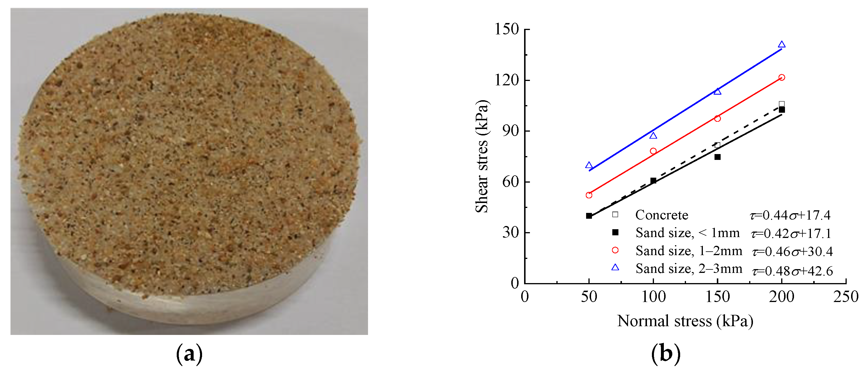
2.3. Quick-Shear Behavior of Pile–Soil Interface

Concrete jacked pile has a rough surface significantly different from smooth aluminum piles [6,19,34], steel piles [31,33,40], polymethyl methacrylate piles [27], etc. To obtain reasonable penetration resistance and the soil-squeezing effect of a jacked pile, the model pile should be rough to reproduce the inter-surface quick-shear behavior between the concrete pile and natural stiff clay. Here, an acrylic plexiglass pile with a surface stuck by sand uniformly was employed to capture the frictional behavior of the concrete pile, as shown in Figure 3a. Figure 3b provides the relationships between shear stress τ and normal force σ using sands with diameters of <1 mm, 1–2 mm, and 2–3 mm by performing direct shear tests at a rate of 0.8 mm/min. Note that the quick-shear behavior for the concrete–soil interface was also examined for comparison. It shows that the interface frictional angle and cohesion increased with the sand size, and the acrylic plexiglass sample stuck uniformly by sands with sizes < 1 mm reproduced the shear behavior of the concrete–clay interface well. Therefore, an acrylic plexiglass pile uniformly stuck by sand with a size of < 1 mm (Figure 4) was employed in the physical model test to simulate a concrete pile. Note that the pile end also plays an important role in pile penetration. Therefore, a steel pile end (Figure 4) in the shape of a cross was employed in the test, which has been widely employed in jacked pile engineering in China. The characteristic of the model pile is provided in Table 2.

2.4. Monitoring System

Figure 5 provides the arrangements of the monitoring sensors in the tests. A force sensor was installed between the shaft and the pile to monitor the total penetration resistance. In the ground, three earth pressure cells and pore pressure cells were buried at depths of 50 mm, 100 mm, and 150 mm to monitor the squeezing stress and pore pressure, respectively. On the surface, three displacement sensors were placed with a spacing of 50 mm to monitor the soil-squeezing displacement. Note that the resistance at the pile end could not be monitored directly because the actual shaped pile end was employed instead of an earth pressure cell in the test. Therefore, two strain gauges were attached to the pile top and end to monitor the pile strain, which could be used to calculate the total penetration and end resistances. It is worth mentioning that the monitored data in the reduced-scale model tests could hardly be scaled to the real-life jacked pile accurately because some important factors (e.g., soil particles and stress level, cohesion) were not perfectly scaled using the in situ clays instead of similar material, which has been widely employed in geotechnical engineering [6,34].

2.5. Test Preparation

The testbed was filled with five layers, with each layer measuring 160 mm. For stiffer clay, the dried and crushed clay particles were mixed with 1% chunam by mass uniformly by a mixer. Then, the mixture was wetted to a water content of 20.2%, which was the same as the natural stiff clay. Afterwards, the stiffer clay was poured into the soil bin and compacted to the target dry density layer by layer to a final thickness of 800 mm. As for the softer clay, the dried clay particles were wetted to a water content of 40.1% and then poured into the soil bin layer by layer. Note that more water was sprayed on the ground to ensure saturation after compacting each layer to the target density. After finishing the soil filling, the testbed was consolidated for one week.
The jacked pile penetration showed a significant squeezing effect on the adjacent pile, leading to engineering accidents, including breakage and floating of the adjacent pile. Therefore, after the jacked pile was forced at the center to study the penetration resistance and soil-squeezing effect, another pile was forced at different pile spacings from the center pile to investigate the soil-squeezing effect on the adjacent pile. Two groups of tests were performed, i.e., group 1 in stiffer clay and group 2 in softer clay, as shown in Table 3. In light of the suggested pile spacing in Chinese standards [47] being 3.5–4.5 D, the pile spacings were chosen to be 2.5 D, 3.5 D, 4.5 D, and 5.5 D in the test.

3. Results

3.1. Bearing Behavior and Soil Squeezing Effect in the Ground

3.1.1. Total Penetration Resistance

Figure 6 presents the monitored total penetration resistance Ft monitored by the force sensor in stiffer and softer clays. It shows that Ft increased rapidly at the beginning and then increased at a lower rate. This is because both the pile end and the side resistances increased significantly at the beginning, which led to a relatively high increasing rate. As the pile penetrated, the resistance at the pile end reached the peak and then tended to be stable, whereas the resistance at pile side increased continually due to the increasing contacting side area, which contributed to the increasing total penetration resistance at a lower increasing rate. As expected, the stiffer clay exhibited a much larger penetration resistance due to the higher shear strength and a higher increasing rate due to the lower compressibility compared with the softer clay. Note that the penetration resistance in stiff clay seemed to increase more rapidly when the penetration depth exceeded 250 mm, which was probably caused by the inevitable inhomogeneity in the ground.

3.1.2. Resistance at Pile End

The monitored strain at the pile top and end was employed to calculate the axial force at the pile top and end using the following equation based on elastic mechanics [48]:
F = E ε z π ( r o 2 r i 2 )
where E is the pile modulus, εz is the measured strain, and ro and ri are the outside and inside radius of the pile, respectively. Note that the axial force at the pile end is similar in value to the total penetration resistance Ft and that the axial force at the pile end is similar to the resistance at the pile end Fe. Figure 7 provides the calculated Ft and Fe in stiffer and softer clays. It shows that the calculated Ft evolved in a similar trend and value as that monitored by the force sensor. Therefore, the strain at the top and end could be employed to show the evolution of Fe/Ft, as shown in Figure 8. Figure 8 shows that Fe/Ft exhibited a softening behavior, which first increased to a peak and then gradually decreased. It can be easily understood that the increase in Fe caused by soil strength was larger than that of the resistance at pile side Fs due to the increasing contact area at the beginning. After the soil beneath the pile end failed, Fe tended to be stable and Fs increased continually, which led to a decreasing Fe/Ft. It is worth mentioning that the peak and final Fe/Ft for stiffer and softer clays were quite similar in value, probably because pile–soil quick-shear behavior decreased with the soil’s mechanical properties. However, due to lower compressibility, the penetration depth needed to reach the peak Fe/Ft was larger in stiffer clay. Nevertheless, the ratio of the resistance at the pile end to the total penetration resistance in stiffer clay can directly refer to that in softer clay.

3.1.3. Earth Pressure

Figure 9 presents the evolutions of the horizontal pressures at different depths to show the soil-squeezing stress. Note that the initial earth pressure caused by consolidation was set to be 0 kPa, and only the pressure due to pile penetration was monitored here. Figure 9 shows that the horizontal earth pressure first increased to a peak with the increasing penetration depth and then decreased gradually. Note that the peak earth pressures in the stiffer clay were larger than those in the softer clay, indicating that larger squeezing stress appeared in the stiffer clay.
In cohesionless soil, the peak pressure increased to the peak value at the buried depth of the earth pressure, i.e., the distance between the penetrator cone and earth pressure cell dp approached 0 mm when the earth pressure reached the peak [14]. However, dp in the cohesive soil here was non-zero and increased with the buried depth of the earth pressure cell, as shown in Figure 10. Note that the dp for the cell buried at a depth of 300 mm was chosen to be 50 mm, although the earth pressures were still increasing. In addition, dp in the softer clay was much larger than that in the stiffer clay at the same buried depth. This is because both the resistances at the pile end and the side contributed to the increasing earth pressure. However, the resistance at the pile end increased rapidly to the peak and then tended to be stable, whereas the resistance at pile side continuously increased, as shown in Figure 5. Consequently, the resistance at the pile end contributed more to the shallow earth pressure cell, whereas the resistance at the pile side contributed more to the deep earth pressure cell.

3.1.4. Pore Pressure

Previous research has shown that the pore pressure in saturated clay increases significantly during pile penetration, which weakens the soil shear strength and leads to low pile resistance [15]. Figure 11 provides the pore pressure evolution in both the stiffer and the softer clay. It shows that the pore pressure increased rapidly to peak when the pile approached and then tended to be stable, which is different from the earth pressure, which decreased significantly after the peak value. This is because several days were needed for the pore pressure to dissipate due to clay’s low permeability. In addition, the peak pore pressures in stiffer clay were much smaller than in softer clay, although the earth pressures were larger, as shown in Figure 9. It can be easily understood that the stiffer clay was unsaturated and the soil skeleton bore more squeezing stress from pile penetration.

3.1.5. Soil-Squeezing Displacement

Figure 12 shows the ground heave in the stiffer and the softer clay, i.e., the soil-squeezing displacement on the ground surface. Note that no ground heave was observed at the point with a distance of 150 mm from the pile. Figure 12 shows that the ground heaved more significantly with the softer clay than with the stiffer clay. In particular, the ground heave at the point with a distance of 50 mm in the softer clay was nearly four times larger than that in the stiffer clay. This is because the softer clay was easier to compact and move due to its higher compressibility.
Above all, it can be concluded that both soil-squeezing stress and soil-squeezing displacement exist in the ground due to pile penetration. Compared with the softer clay, the stiffer clay exhibited larger soil-squeezing stress due to the higher shear strength and smaller soil-squeezing displacement due to the low compressibility.

3.2. Soil-Squeezing Effect on the Adjacent Pile

3.2.1. Soil-Squeezing Displacement on the Adjacent Pile

The maximum soil-squeezing displacement on the adjacent pile was nearly 1 mm, which could barely be observed. Thus, the displacement sensors placed on the pile top were employed to monitor the soil-squeezing displacements. Figure 13 provides the center pile’s vertical flotation and horizontal deviation caused by adjacent pile penetration at different pile spacings in the stiffer and the softer clay. Note that larger vertical flotation and horizontal pile deviation lead to pile floating in engineering, which affects the pile-bearing behavior. Figure 13 shows that the vertical pile flotation and horizontal pile deviation increased nearly linearly with the penetration depth. As expected, the smaller the pile spacing, the larger the vertical flotation and horizontal deviation.
Figure 14 presents the relationships between vertical flotation/horizontal deviation and the pile spacing in the stiffer and the softer clay. Figure 14 shows that the vertical pile flotation and the horizontal pile deviation in the softer clay were much larger, indicating that the piles were easier to float and incline. This is because the soil squeezing displacement is larger and the pore pressure is higher in softer clay, leading to larger vertical pile flotation and horizontal pile deviation. Therefore, from the view of soil-squeezing displacement due to adjacent pile penetration, the spacing distance necessary to reduce the soil-squeezing effect is larger in softer clay. The linear, exponential, and logarithmic equations were employed to describe the relationships between vertical flotation/horizontal deviation and pile spacing. The fitting equations are provided in Table 4, which shows that the nonlinear equation form y = ae−bx could be employed to describe the effect of pile spacing on the vertical flotation/horizontal deviation of the adjacent pile. In other words, the vertical flotation/horizontal deviation of the adjacent pile could be predicted using the equation form y = ae−bx with the help of some filed test data.

3.2.2. Soil-Squeezing Stress on the Adjacent Pile

Figure 15 presents the pile strain at the pile end due to adjacent pile penetration in the stiffer and the softer clay. Note that large pile strain due to soil-squeezing stress leads to pile breakage in engineering. Figure 15 shows that as the pile spacing increased, the strain at the pile end decreased significantly, which implies that the squeezing stress at the pile end decreased with the increasing pile spacing, as expected.
Figure 16 presents the relationships between the strain at the pile end and the pile spacing in the stiffer and the softer clay. Figure 16 shows the strain at the pile end in the stiffer clay was larger than that in the softer clay, indicating that larger squeezing stress appeared on the pile end in the stiffer clay. Therefore, from the view of soil-squeezing stress due to adjacent pile penetration, the spacing distance necessary to reduce the soil-squeezing effect is larger in softer clay. In addition, the nonlinear equation form y = ae−bx can also be employed to describe the effect of pile spacing on the strain at the adjacent pile end.
Above all, it can be concluded that the soil-squeezing effect due to adjacent pile penetration also leads to a smaller squeezing displacement but a larger squeezing force on the pile in stiffer clay than in softer clay due to the high shear strength and low compressibility of stiffer clay. Consequently, the pile spacing for stiffer clay should be determined mainly by controlling the pile strain caused by the squeezing stress to avoid pile breakage, whereas the pile spacing for softer clay should be determined mainly by controlling the pile vertical flotation and horizontal deviation to avoid pile flotation. In addition, high-strength PHC piles should be employed in stiff clay to avoid pile breakage.

4. Conclusions

To better design and construct jacked piles in stiff clay areas of Central China, two groups of jacked pile penetration tests were performed with a rough pile that can reproduce the quick-shear behavior of the pile–soil interface, i.e., group 1 in stiffer clay and group 2 in softer clay for comparison, to study the bearing behavior and soil-squeezing effect in stiffer clay. For each group, the adjacent pile was additionally penetrated at different pile spacings to investigate the soil-squeezing effect due to adjacent pile penetration. The main conclusions are summarized as follows:
(1)
During pile penetration, the resistance at the pile end increased rapidly at the beginning and then tended to be stable with fluctuations, whereas the resistance on the pile side continually increased due to the increasing contact area. As a result, the total penetration resistance increased rapidly at the beginning and then increased at a lower increasing rate.
(2)
The ratio of the resistance at the pile end to the total penetration resistance exhibited a softening behavior, which first increased to a peak and then gradually decreased. The peak and final proportion for the stiffer and the softer clay were similar in value, whereas the penetration depth needed to reach the peak proportion was larger in the stiffer clay due to its low compressibility.
(3)
There was soil-squeezing stress and soil-squeezing displacement in the ground due to pile penetration. In the stiffer clay, the soil-squeezing stress was larger due to the higher strength, whereas the soil-squeezing displacement was smaller due to the low compressibility.
(4)
The nonlinear equation form y = aebx could be employed to describe the effect of pile spacing on the vertical flotation, horizontal deviation, and pile strain of the adjacent pile.

Author Contributions

Visualization, writing, funding acquisition, and formal analysis, B.X.; methodology, investigation, and data curation, G.L.; conceptualization, validation, and resources. X.C. All authors have read and agreed to the published version of the manuscript.

Funding

The research was funded by the Science and Technology Plan for Housing and Urban Rural Construction in Anhui Province (2021-YF27) and the Anhui Province Key Laboratory of Green Building and Assembly Construction (2021-JKYL1-002).

Data Availability Statement

Not applicable.

Conflicts of Interest

The authors declare no conflict of interest.

References

  1. Doherty, P.; Gavin, K.; Gallagher, D. Field investigation of base resistance of pipe piles in clay. Proc. Inst. Civ. Eng. Geotech. Eng. 2010, 163, 13–22. [Google Scholar] [CrossRef]
  2. Cooke, R.W.; Price, G.; Tarr, K. Jacked piles in London Clay: A study of load transfer and settlement under working conditions. Geotechnique 1979, 29, 113–147. [Google Scholar]
  3. Zhang, Z.; Wang, Y.H. Examining setup mechanisms of driven piles in sand using laboratory model pile tests. J. Geotech. Geoenviron. Eng. 2015, 141, 04014114. [Google Scholar] [CrossRef]
  4. Han, F.; Ganju, E.; Salgado, R.; Prezzi, M. Comparison of the load response of closed-ended and open-ended pipe piles driven in gravelly sand. Acta Geotech. 2019, 14, 1785–1803. [Google Scholar]
  5. Liu, C.; Tang, X.; Wei, H.; Wang, P.; Zhao, H. Model tests of jacked-pile penetration into sand using transparent soil and incremental particle image velocimetry. KSCE J. Civ. Eng. 2020, 24, 1128–1145. [Google Scholar]
  6. Wang, Y.; Sang, S.; Liu, X.; Huang, Y.; Zhang, M.; Miao, D. Model test of jacked pile penetration process considering influence of pile diameter. Front. Phys. 2021, 9, 616410. [Google Scholar]
  7. Hwang, J.H.; Liang, N.; Chen, C.H. Ground response during pile driving. J. Geotech. Geoenviron. 2001, 127, 939–949. [Google Scholar] [CrossRef]
  8. Baligh, M.M. Strain path method. Int. J. Geotech. Eng. 1985, 111, 1108–1136. [Google Scholar] [CrossRef]
  9. Wang, Y.; Li, L.; Gong, W. An analytical solution for settlement of jacked piles considering pile installation effects. Eur. J. Environ. Civ. Eng. 2022, 26, 200–215. [Google Scholar] [CrossRef]
  10. Zhang, Q.Q.; Liu, S.W.; Zhang, S.M.; Zhang, J.; Wang, K. Simplified non-linear approaches for response of a single pile and pile groups considering progressive deformation of pile–soil system. Soils Found. 2016, 56, 473–484. [Google Scholar]
  11. Burd, H.J.; Abadie, C.N.; Byrne, B.W.; Houlsby, G.T.; Martin, C.M.; McAdam, R.A.; Andrade, M.P. Application of the PISA design model to monopiles embedded in layered soils. Géotechnique 2020, 70, 1067–1082. [Google Scholar] [CrossRef]
  12. Chen, H.; Li, L.; Li, J. An elastoplastic solution for spherical cavity undrained expansion in overconsolidated soils. Comput. Geotech. 2020, 126, 103759. [Google Scholar]
  13. Hu, P.; Stanier, S.A.; Cassidy, M.J.; Wang, D. Predicting peak resistance of spudcan penetrating sand overlying clay. J. Geotech. Geoenviron. 2014, 140, 04013009. [Google Scholar] [CrossRef]
  14. Jiang, M.; Dai, Y.; Cui, L.; Shen, Z.; Wang, X. Investigating mechanism of inclined CPT in granular ground using DEM. Granul. Matter 2014, 16, 785–796. [Google Scholar] [CrossRef]
  15. Lei, H.Y.; Li, X.; Lu, P.Y.; Huo, H.F. Field test and numerical simulation of squeezing effect of pipe pile. Rock Soil Mech. 2012, 33, 1006–1012. [Google Scholar]
  16. Wang, Y.Y.; Sang, S.K.; Zhang, M.Y.; Jeng, D.S.; Yuan, B.X.; Chen, Z.X. Laboratory study on pile jacking resistance of jacked pile. Soil Dyn. Earthq. Eng. 2022, 154, 107070. [Google Scholar] [CrossRef]
  17. Zhang, L.M.; Wang, H. Field study of construction effects in jacked and driven steel H-piles. Géotechnique 2009, 59, 63–69. [Google Scholar] [CrossRef]
  18. Gill, D.R.; Lehane, B. An optical technique for investigating soil displacement patterns. Geotech. Test J. 2001, 24, 324–329. [Google Scholar]
  19. Huang, B.; Zhang, Y.; Fu, X.; Zhang, B. Study on visualization and failure mode of model test of rock-socketed pile in softer rock. Geotech. Test J. 2018, 42, 1624–1639. [Google Scholar]
  20. Lalicata, L.M.; Desideri, A.; Casini, F.; Thorel, L. Experimental observation on laterally loaded pile in unsaturated silty soil. Can. Geotech. J. 2019, 56, 1545–1556. [Google Scholar] [CrossRef]
  21. Liu, E.L.; Shen, Z.J. Experimental study on mechanical properties of artificially structured soils. Rock Soil Mech. 2007, 28, 679–683. [Google Scholar]
  22. White, D.J.; Bolton, M.D. Displacement and strain paths during plane-strain model pile installation in sand. Géotechnique 2004, 54, 375–397. [Google Scholar] [CrossRef]
  23. Randolph, M.F.; Wroth, C.P. An analytical solution for the consolidation around a driven pile. Int. J. Numer. Anal. Met. 1979, 3, 217–229. [Google Scholar] [CrossRef]
  24. Henke, S.; Grabe, J. Simulation of pile driving by 3-dimensional Finite-Element analysis. In Proceedings of the 17th European Young Geotechnical Engineers’ Conference, Zagreb, Croatia, 20–22 July 2006; pp. 215–233. [Google Scholar]
  25. Su, D.; Wu, Z.; Lei, G.; Zhu, M. Numerical study on the installation effect of a jacked pile in sands on the pile vertical bearing capacities. Comput. Geotech. 2022, 145, 104690. [Google Scholar]
  26. Li, L.; Wu, W.; Liu, H.; Lehane, B. DEM analysis of the plugging effect of open-ended pile during the installation process. Ocean Eng. 2021, 220, 108375. [Google Scholar]
  27. Liu, J.; Duan, N.; Cui, L.; Zhu, N. DEM investigation of installation responses of jacked open-ended piles. Acta Geotech. 2019, 14, 1805–1819. [Google Scholar]
  28. Katti, D.R.; Matar, M.I.; Katti, K.S.; Amarasinghe, P.M. Multiscale modeling of swelling clays: A computational and experimental approach. KSCE J. Civ. Eng. 2009, 13, 243–255. [Google Scholar] [CrossRef]
  29. Bayesteh, H.; Hoseini, A. Effect of mechanical and electro-chemical contacts on the particle orientation of clay minerals during swelling and sedimentation: A DEM simulation. Comput. Geotech. 2021, 130, 103913. [Google Scholar]
  30. Wen, L.; Kong, G.; Li, Q.; Zhang, Z. Field tests on axial behavior of grouted steel pipe micropiles in marine softer clay. Int. J. Geomech. 2020, 20, 06020006. [Google Scholar] [CrossRef]
  31. Lim, J.K.; Lehane, B.M. Set-up of pile shaft friction in laboratory chamber tests. Int. J. Phys. Model. Geo. 2014, 14, 21–30. [Google Scholar] [CrossRef]
  32. Paniagua, P.; Andó, E.; Silva, M.; Emdal, A.; Nordal, S.; Viggiani, G. Soil deformation around a penetrating cone in silt. Geotech. Lett. 2013, 3, 185–191. [Google Scholar] [CrossRef]
  33. White, D.J.; Lehane, B.M. Friction fatigue on displacement piles in sand. Géotechnique 2004, 54, 645–658. [Google Scholar]
  34. Ye, Z.H.; Zhou, J.; Tang, S.D. Model test on pile bearing behaviors in clay under different pile tip conditions. J. Tongji Univ. (Nat. Sci.) 2009, 37, 733–737. [Google Scholar]
  35. Arshad, M.I.; Tehrani, F.S.; Prezzi, M.; Salgado, R. Experimental study of cone penetration in silica sand using digital image correlation. Géotechnique 2014, 64, 551–569. [Google Scholar] [CrossRef]
  36. Mo, P.Q.; Marshall, A.M.; Yu, H.S. Layered effects on soil displacement around a penetrometer. Soils Found. 2017, 57, 669–678. [Google Scholar] [CrossRef]
  37. Ni, Q.C.C.I.; Hird, C.C.; Guymer, I. Physical modelling of pile penetration in clay using transparent soil and particle image velocimetry. Géotechnique 2010, 60, 121–132. [Google Scholar] [CrossRef]
  38. Qi, C.G.; Zheng, J.H.; Zuo, D.J.; Chen, G. Measurement on soil deformation caused by expanded-base pile in transparent soil using particle image velocimetry (PIV). J. Mt. Sci. 2017, 14, 1655–1665. [Google Scholar] [CrossRef]
  39. Chen, Z.; Omidvar, M.; Iskander, M.; Bless, S. Modelling of projectile penetration using transparent soils. Int. J. Phys. Model. Geo. 2014, 14, 68–79. [Google Scholar] [CrossRef]
  40. Paik, K.; Salgado, R. Determination of bearing capacity of open-ended piles in sand. J. Geotech. Geoenviron. 2003, 129, 46–57. [Google Scholar] [CrossRef]
  41. Gui, M.W.; Bolton, M.D.; Garnier, J.; Corte, J.F.; Bagge, G.; Laue, J.; Renzi, R. Guidelines for cone penetration tests in sand. In Centrifuge; Balkema: Rotterdam, The Netherlands, 1998; pp. 155–160. [Google Scholar]
  42. Mo, P.Q.; Marshall, A.M.; Yu, H.S. Centrifuge modelling of cone penetration tests in layered soils. Géotechnique 2015, 65, 468–481. [Google Scholar] [CrossRef]
  43. Guo, Y.; Cui, W. Experimental study on application of PHC piles in paleo-clay area. Chin. J. Geotech. Eng. 2011, 33, 108–115. [Google Scholar]
  44. Suebsuk, J.; Horpibulsuk, S.; Liu, M.D. Modified Structured Cam Clay: A generalised critical state model for destructured, naturally structured and artificially structured clays. Comput. Geotech. 2010, 37, 956–968. [Google Scholar] [CrossRef]
  45. Amorosi, A.; Kavvadas, M. A constitutive model for structured soils. Géotechnique 2000, 50, 263–273. [Google Scholar]
  46. Savvides, A.A.; Papadrakakis, M. A computational study on the uncertainty quantification of failure of clays with a modified cam-clay yield criterion. SN Appl. Sci. 2021, 3, 659. [Google Scholar] [CrossRef]
  47. JGJ 94-2008; Ministry of Construction of the People’s Republic of China. Technical Code for Building Pile Foundations. China Architecture & Building Press: Beijing, China, 2008.
  48. Wu, J.L. Elasticity; Higher Education Press: Beijing, China, 2001. [Google Scholar]
Figure 1. Experimental apparatus.
Buildings 13 02609 g001
Figure 2. Stress–strain relationships of the stiffer and softer clays.
Buildings 13 02609 g002
Figure 3. Acrylic plexiglass sample stuck uniformly by sands for direct shear test: (a) sample; (b) shear–stress relationship.
Buildings 13 02609 g003
Figure 4. Model pile (a) and pile end (b).
Buildings 13 02609 g004
Figure 5. Test schematic diagram.
Buildings 13 02609 g005
Figure 6. Total pile penetration resistances in the stiffer and the softer clay.
Buildings 13 02609 g006
Figure 7. Pile end resistances in the stiffer and the softer clay.
Buildings 13 02609 g007
Figure 8. Contribution of the pile end resistances.
Buildings 13 02609 g008
Figure 9. Soil-squeezing stress in the ground at a depth of (a) 100 mm, (b) 200 mm, and (c) 300 mm.
Buildings 13 02609 g009
Figure 10. Relationships between dp and buried depth.
Buildings 13 02609 g010
Figure 11. Pore pressure in the ground at a depth of (a) 100 mm, (b) 200 mm, and (c) 300 mm.
Buildings 13 02609 g011
Figure 12. Ground heave.
Buildings 13 02609 g012
Figure 13. Vertical pile flotation and horizontal pile deviation due to adjacent pile penetration: (a) stiffer clay; (b) softer clay.
Buildings 13 02609 g013
Figure 14. Relationships of vertical flotation (a)/horizontal deviation (b) and pile spacing.
Buildings 13 02609 g014
Figure 15. Strain at the pile end due to adjacent pile penetration: (a) stiffer clay; (b) softer clay.
Buildings 13 02609 g015
Figure 16. Relationships between the strain at the pile end and the pile spacing.
Buildings 13 02609 g016
Table 1. Physical and mechanical parameters of stiffer and softer clays.
SoilSpecific GravityInternal Friction AngleCohesionBulk DensityWater Content
Stiffer clay2.7313.8°82.3 kPa1.902 g/cm320.2 (%)
Softer clay2.7310.6°46.2 kPa2.275 g/cm340.1 (%)
Table 2. Model pile characteristics.
MaterialSand SizeOutside Diameter (m)Inside Diameter (m)Pile Length (m)Elastic Modulus (GPa)
Acrylic plexiglass<1 mm0.04 m0.020.73.16
Table 3. Test scheme.
Test GroupSoilPile SpacingPenetration Velocity
1Stiffer clay2.5 D0.5 mm/s
3.5 D0.5 mm/s
4.5 D0.5 mm/s
5.5 D0.5 mm/s
2Softer clay2.5 D0.5 mm/s
3.5 D0.5 mm/s
4.5 D0.5 mm/s
5.5 D0.5 mm/s
Table 4. Fitting equations.
SoilEquationHorizontal DeviationVertical Flotation
Stiffer clayLinearIh = −0.093nD + 0.5545, R2 = 0.972Iv = −0.086nD + 0.499, R2 = 0.996
ExponentialIh = 1.23e(−0.13nD), R2 = 0.981Iv = 1.16e(−0.14nD), R2 = 0.966
LogarithmicIh = −0.356In(nD) + 0.66, R2 = 0.979Iv = −0.33In(nD) + 0.6, R2 = 0.992
Softer clayLinearIh = −0.342nD + 1.848, R2 = 0.802Iv = −0.091nD + 0.611, R2 = 0.854
ExponentialIh = 13.75e(−0.25nD), R2 = 0.989Iv = 1.17e(−0.1nD), R2 = 0.945
LogarithmicIh = −1.363In(nD) + 2.319, R2 = 0.884Iv = −0.359In(nD) + 0.73, R2 = 0.920
Disclaimer/Publisher’s Note: The statements, opinions and data contained in all publications are solely those of the individual author(s) and contributor(s) and not of MDPI and/or the editor(s). MDPI and/or the editor(s) disclaim responsibility for any injury to people or property resulting from any ideas, methods, instructions or products referred to in the content.

