Article

Comparative Analysis of Buffer and Damper Positions for Increasing the Seismic Performance of Suspension Bridge

1
School of Civil Engineering, Dalian University of Technology, Dalian 116024, China
2
Design & Institute of Civil Engineering & Architecture of Dalian University of Technology Company Limited, Dalian 116024, China
3
State Key Laboratory of Coastal and Offshore Engineering, Dalian University of Technology, Dalian 116024, China
*
Author to whom correspondence should be addressed.
Buildings 2023, 13(1), 81; https://doi.org/10.3390/buildings13010081
Submission received: 10 October 2022 / Revised: 29 November 2022 / Accepted: 26 December 2022 / Published: 29 December 2022
(This article belongs to the Special Issue Research on Statics and Dynamics of Structures)

Abstract

:
In this research, a finite element model is established to investigate effective seismic control schemes for a self-anchored suspension bridge (SASB) with three towers. Nonlinear dynamic analyses are conducted to evaluate the seismic performance of SASB with different layout schemes of viscous dampers and buffers, which were installed in longitudinal direction and transversal direction, respectively. The responses of the SASB designed with 10 seismic control schemes are compared to ascertain suitable seismic schemes for SASBs. The results show that the number and location of lateral buffers have an important impact on the dynamic characterization of the SASB, especially for the first lateral mode and lateral fundamental frequency. To effectively increase the seismic performance of SASBs with three towers, mounting buffers between the side towers and the main girder of SASBs is an appropriate scheme. The viscous dampers can effectively decrease the dynamic reaction of the towers and longitudinal deformation of the girder under earthquake excitations. The plan involves the installation of dampers between the main concrete stiffening girder and the side towers as the optimal longitudinal seismic scheme for the SASB. The study offers important insights into the seismic design of SASBs with three towers.

1. Introduction

To realize the advantages of an aesthetic structure, better mechanical and economic performance, and broad adaptability under all types of geological conditions, self-anchored suspension bridges (SASBs) have been widely adopted in medium- and small-span bridges. Concrete stiffening girders (CSGs) are widely utilized in SASBs because of the good resistance to high-bearing compressive stress and the lower costs of construction and maintenance. The shortage of CSGs compared to steel girders, hybrid girders, and composite girders is the high density of concrete material, which enlarges the inertia force of CSGS under earthquake excitations. Therefore, it is necessary to make further investigations into the seismic performance of SASBs and to seek effective seismic control schemes decreasing the responses of SASBs under earthquake disasters.
Extensive research has been systematically conducted on the seismic performance of SASBs, especially on the effect of different influencing factors. The dynamic behavior of a suspended structure named the Golden Gate Bridge, including modal shapes and frequencies, was investigated via theoretical analysis, numerical simulation, and model tests [1,2,3,4]. In addition, the seismic response of the Golden Gate Bridge during earthquakes, including in the transverse, longitudinal, and vertical directions, was analyzed. Weak stiffness parts of the structure were identified from the analysis, which provided a reference for the seismic design of this type of bridge. Other studies have shown that the dynamic behavior of long-span suspension bridges (SBs) is tightly connected with the frequency and velocity of earthquake waves, traveling wave effects, multiple excitations, and pile–soil interactions, which should be considered in seismic design and analysis [5,6,7,8].
The traditional seismic scheme for SBs is based on the elastic carrying capacity of the components. However, studies have become increasingly concerned with the dynamic elastic-plastic deformation capacity of the components. Gao et al. [9] analyzed the sectional capacity of a tower by conducting a moment-curvature study of the tower sections while considering the axial forces effects. An optimization analysis of the tower was also performed based on the obtained results. Okuda et al. [10] researched the seismic performance of the original and retrofitted Akashi Kaikyo Bridge by performing pushover analyses.
Achieving a comprehensive improvement in the seismic capacity of SBs has become a focus in research on the seismic characteristics of suspended cable structures. Vader and Tony S. et al. [11] examined the damping effect of diagonal friction dampers and viscous dampers on the Oakland Bay Bridge and proposed a suitable damper layout scheme. Thomas P. Murphy et al. [12] suggested that the installation of dampers can significantly enhance the axial and bending load capacity of SBs. Wang et al. [13] analyzed the seismic response of single-tower SASBs controlled by elastic-plastic steel dampers. Song [14] concluded, based on the response of the Sanchaji Bridge, that the seismic response of a bridge can be effectively controlled by installing viscous dampers with appropriate parameters. Recently, Xu et al. [15,16,17] proposed novel multidimensional vibration isolation and mitigation devices and systematically researched the mechanical properties by experimental and numerical analysis. These devices present good performance for controlling structural dynamic responses and have potential application in SBs. The seismic performance of SBs installed with different types of damper devices should be further investigated.
Compared with ordinary single- or two-tower SBs, multi-tower SBs have a larger number of middle towers without the necessary longitudinal restraints. Three-tower SBs are a reasonable structural configuration, in which the main tower is supported in the middle of traditional two-tower SBs to relieve the stress of the main cables and anchorages. Because the new structures have an additional tower and long-span main girder compared with traditional SBs, the static and dynamic responses of the SBs with multi-towers are obviously different from the behavior of the SBs with single or two towers. In regard to three-tower earth-anchored SBs, Deng et al. [18] analyzed the effects of the longitudinal elastic restraint between the middle tower and the main girder, vertical seismic excitations, and high modes on the seismic performance of the Taizhou Bridge. Wang et al. [19] and Zhang et al. [20] analyzed the structural behaviors of three-tower SBs, such as the vertical, torsional, and horizontal stiffness of the main girder, and presented their influence on the dynamic properties of the SB. Jiao et al. [21] discussed the seismic reaction of a three-tower SB. Wang [22] discovered that traveling wave effects have an appreciable influence on the seismic responses of long-span SBs.
However, only a few studies have addressed the mechanical characteristics of SASBs with three towers. Fang et al. [23] analyzed the dynamic behaviors and parameters of a three-tower SASB with a steel stiffening girder. Chen et al. [24] investigated the influence of different constraint systems on the saddle in the stress and deformation of SASBs by numerical simulation. The tower stiffness and the different longitudinal connections between the main girder and the towers have important roles in the vibration frequency and seismic performance of SASBs [25,26].
Because the concrete main girder of multi-tower SASBs has a significantly high mass, the dynamical problems of this type of bridge are more salient and severe. To ensure the seismic safety of a new structure, it is important to identify some reasonable seismic measures. This prospective study was designed to investigate an effective seismic control scheme for a three-tower SASB with a concrete stiffening girder (CSG). The effects of lateral buffers on the dynamic characteristics (including the natural frequency and mode shapes of the lateral vibrations) and seismic responses of the bridge were analyzed. The effects of different longitudinal damper schemes on the seismic response of the girder and towers were also investigated. It is expected that the conclusion of this paper will be useful to professionals and researchers examining three-tower SASBs.

2. Buffers and Damper Layout Schemes

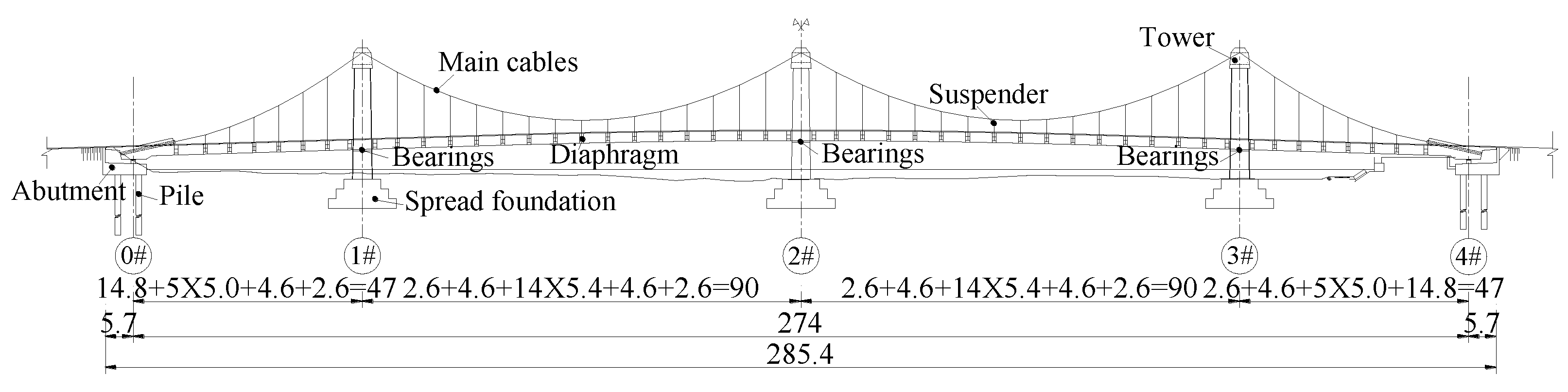
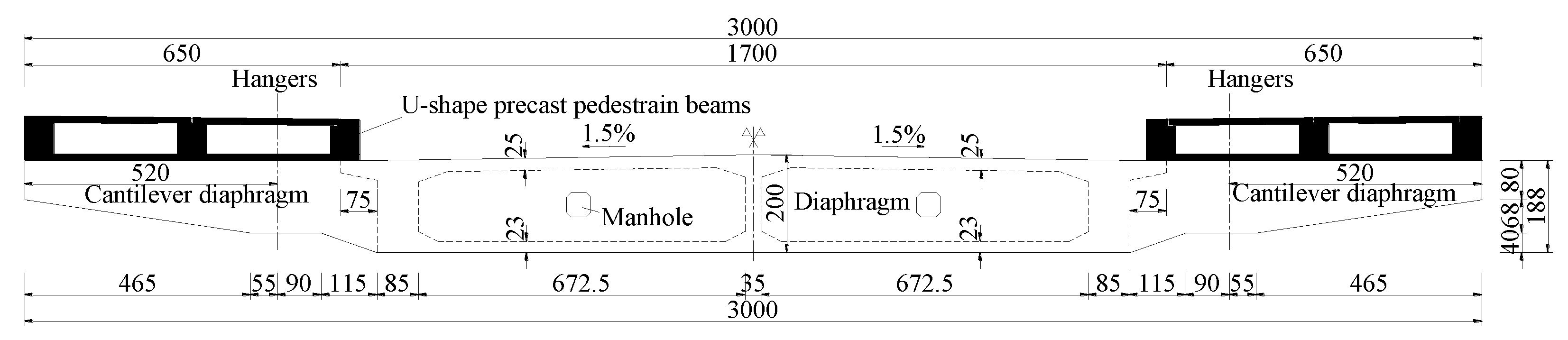
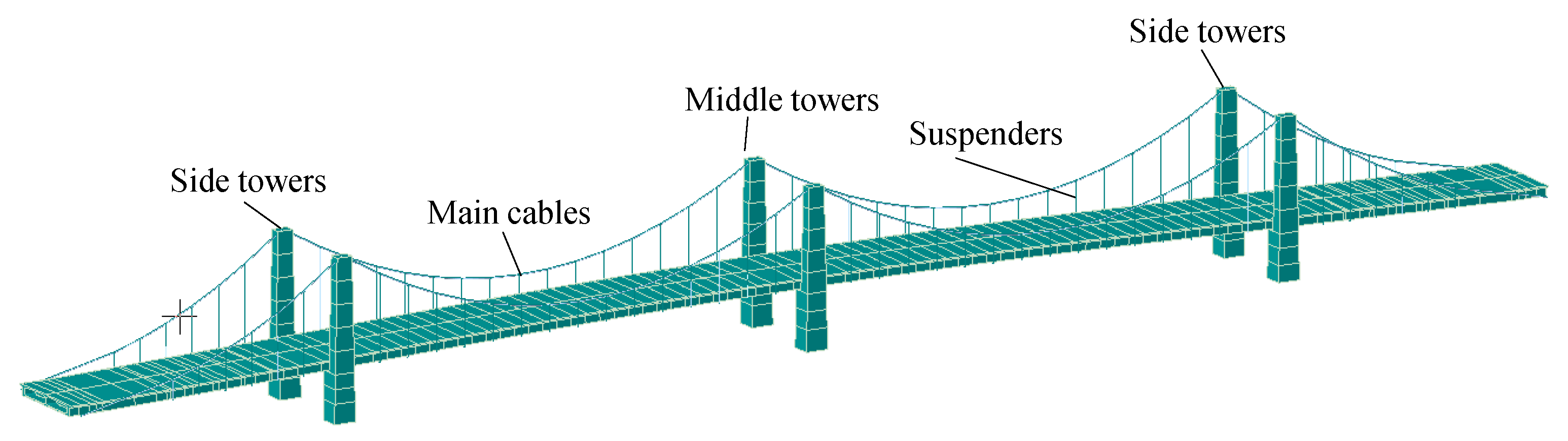
2.1. Introduction of the Researched Bridge

The bridge utilized in this investigation is located in Dalian City, China, and is a SASB with three towers, four vehicle lanes, and two pedestrian lanes. Figure 1 gives the general arrangement and sizes of each main part. The total length and width of this bridge are 285.4 m and 30 m, respectively. The span sizes are 47 m, 90 m, 90 m, and 47 m. The height of the towers is 26.86 m and the cross-section of each tower is a solid rectangle with variable size along the height. The foundation of the towers is a spread foundation, and concrete drilling piles are settled under the bridge abutments. The main cables are anchored by heavy concrete masses settled at both ends of the main girder. Each main cable plane includes two prefabricated parallel-wire-strand (PPWS) cables with cold-casting heading anchorages and high-density polyethylene (HDPE) jackets. The lateral distance between the two PPWS cables is 27.5 cm, and the center spacing is enhanced to 1.2 m at the anchorage blocks of the girder. Each PPWS cable consists of 649 high-strength wires. The four shortest suspenders are bonded to the main cables using rigid steel rods. Other suspenders are flexible, connecting PPWS cables and the main girder. The saddle body adopts a cast structure with two leaved, U-transverse grooves to cross the main cable. All the saddles are fastened on the top of the towers after bridge completion.
Figure 2 shows details of the CSG. The girder is a prestressed concrete structure with a single box and double-room section. The maximum depth of the stiffening girder and width are 200 cm and 1700 cm, respectively. Two overhangs with a width of 75 cm are designed at the two sides of the girder. The thicknesses of the middle web, side web, bottom plate, and top plate are 5 cm, 85 cm, 23 cm, and 2.5 cm, respectively. Concrete diaphragms are attached onto the suspender position of the girder. The distance between two diaphragms is 540 cm in the main spans and 500 cm in the side spans. The precast pedestrian boards are erected above the cantilever diaphragms.

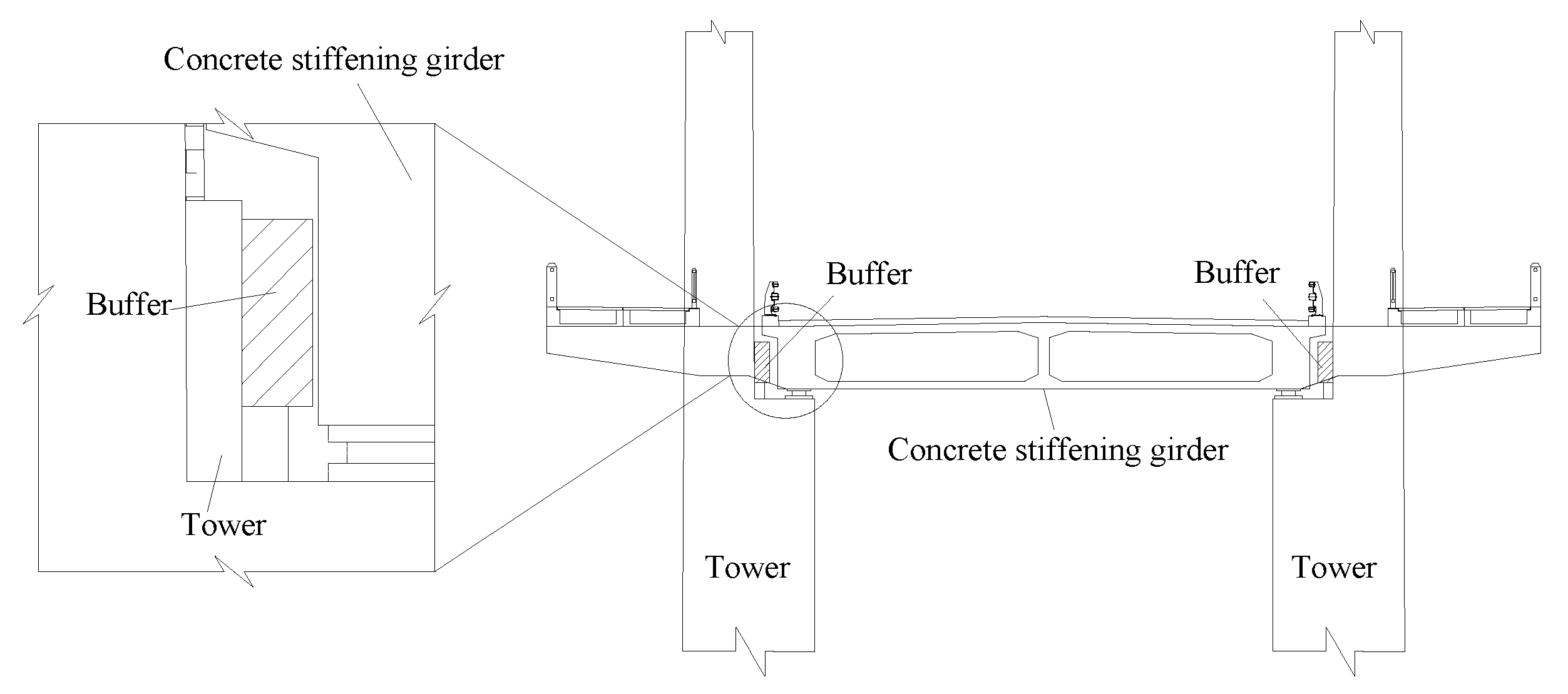
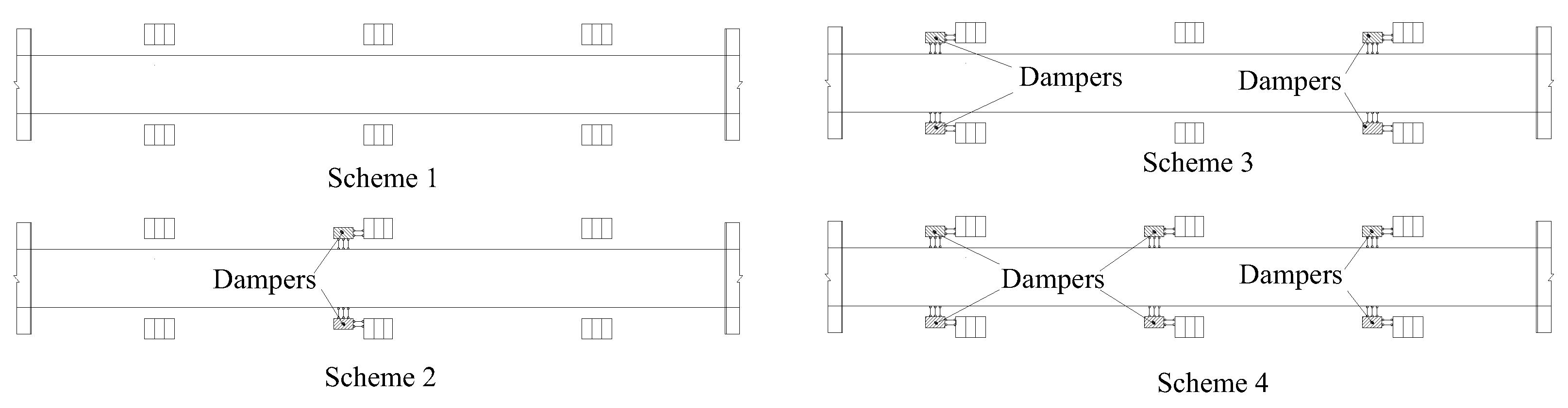
2.2. Buffers Layout Schemes

To more conveniently install the bearings and dampers between the towers and the CSG, an increasing transverse dimension of the tower is adopted in the area under the girder. Rubber buffers are installed between the stiffening girder and the tower column in transversal direction, whereas viscous dampers are placed between the girder and the tower column in longitudinal direction.
In general, buffers are installed between the tower column and the CSG in the transverse seismic design of bridges. The layout of the buffers significantly affected the vibration modal and period of the bridge. The buffers were installed in pairs between the tower column and the CSG, as shown in Figure 3. The buffer is fixed on the tower, and there is a gap between the buffer and the CSG. The buffer will separate from the CSG when the tower and the CSG move in opposite directions. So, one buffer suffers a compressive force during an earthquake, and the opposite buffer relieves compress stress and resets to its original position.
The different layout schemes of the buffers are shown in Figure 4. The mechanical parameters of the buffers were determined according our previous research published in reference [27]. The axial stiffness of the buffer used in the analysis is 800,000 kN/m.
Scheme 1: there are no buffers on the bridge. The stiffening girder is lateral fixed with each tower and abutment to prevent large deformation in the lateral direction.
Scheme 2: four buffers were installed on the bridge between the two side towers and the stiffening girder.
Scheme 3: six buffers were installed on the bridge between all three towers and the stiffening girder.
Scheme 4: six buffers were installed on the bridge between the middle tower and abutments and the stiffening girder.
Scheme 5: eight buffers were installed on the bridge between the side towers and abutments and the stiffening girder.
Scheme 6: ten buffers were installed on the bridge between all the towers and the abutments and the stiffening girder.

2.3. Comparison and Selection of Longitudinal Seismic Resistance Schemes for the Bridge

The longitudinal seismic response of the three-tower SASB is quite distinct compared with that of conventional two-tower SBs. The large deformation of the CSG in longitudinal direction drastically affects the behavior of the towers. Hence, balancing the internal force distribution in the three towers is a critical key for the seismic design of the three-tower SASB. The layout of the dampers used between the towers and the stiffening girder is an effective method to adjust the internal force distribution of the towers. In this section, viscous dampers were applied to the seismic design of the bridge, and the effect of damper locations on the dynamic response of the bridge under earthquake excitations was discussed.
The installation of the longitudinal viscous damper is shown in Figure 5. The layout schemes of the longitudinal viscous dampers are shown in Figure 6. Considering the weak seismic capacity of the abutments, the dampers were only installed between the towers and the stiffening girder. The effect of the buffer was not considered in this section’s research.
Scheme 1: there are no dampers on the bridge.
Scheme 2: two dampers were installed on the bridge between the columns of the middle tower and the stiffening girder.
Scheme 3: four dampers were installed on the bridge between the columns of the side towers and the stiffening girder.
Scheme 4: six dampers were installed on the bridge between the columns of the towers and the stiffening girder.

3. Numerical Modeling

3.1. Finite Element Model

Midas/Civil software was utilized for the bridge’s three-dimensional finite element model, as shown in Figure 7. In general, a backbone model was adopted to simulate the bridge deck system when conducting the transient analysis of the SBs [16]. A spatial beam element based on the Timoshenko beam theory was used to simulate the CSG. The specific failure process of the towers was not considered, and spatial beam elements with variable cross-sections were used to simulate the towers in the study of the seismic control schemes. Tension-only elements were employed to simulate the main cables and tensile suspenders. Rigid steel rods installed in the four shortest suspenders near the anchorage blocks were simulated by spatial beam elements. The initial geometric stiffness of the elements was in accordance with the initial internal force equilibrium state of the completed bridge.
The elastic connection was adopted to simulate the buffers and bearings between the towers and the stiffening girder. The connection effect between the suspenders and the stiffening girder was modeled by rigid arm elements. To simplify the numerical FE model, the main cables were fastened on top of the towers. Piles and abutments were considered rigid components, and a rigid constraint was applied to the nodes of the rigid arm at both ends of the stiffening girder. In the FE model, the bottoms of the towers were fixed at the bases, and only the vertical degrees of freedom (DOF) of the ends of the girder were restrained. The soil–structure interaction was neglected owing to the strong spread foundation.
The 3D finite element (FE) model consists of 345 nodes and 334 units, of which 158 are beam elements and 176 are tension-only elements. The material parameters of the model are listed in Table 1.
In the FE model, the Maxwell model with a serially connected linear spring element and linear damper element was selected to simulate the viscous damper. The relevance between the damper force and the parameters of the viscous damper was computed according to Equation (1) [11].
F = CVα
where F is the force generated by the damper; C is the damper coefficient, which is related to the structure size of the damper and viscosity of the fluid; V is the speed of the piston, which is related to the internal structure of the damper and external load; and α is the exponent of the velocity. The viscous damper is a linear viscous damper, nonlinear viscous damper, and super linear viscous damper when α = 1, α < 1, and α > 1, respectively.
To compare the different layout schemes of the longitudinal dampers, the corresponding parameters of the mechanical model were selected as C = 2000 kN and α = 0.35 in the Maxwell model.

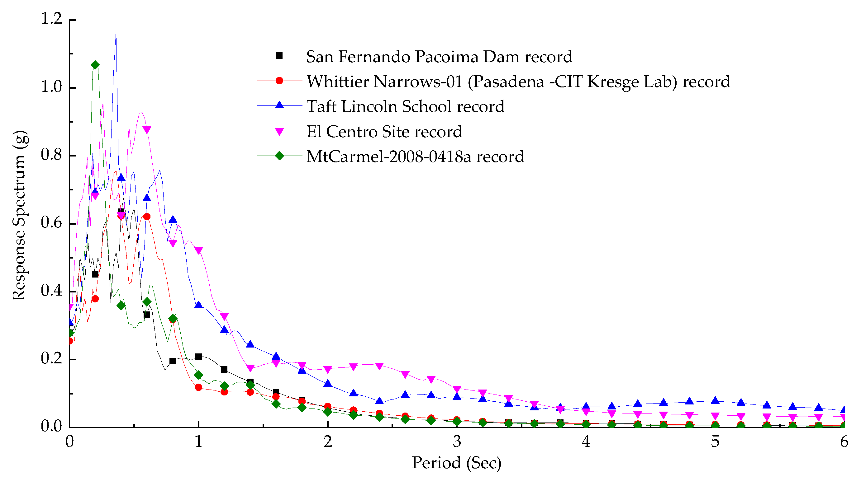
3.2. Earthquake Loads

To research the seismic response of the bridge, five earthquake records, including the San Fernando Pacoima Dam record, Whittier Narrows-01 record, Taft Lincoln School record, El Centro Site record, and MtCarmel-2008-0418a record, were employed as input earthquake waves in the nonlinear time-history analysis. The seismic waves were selected according to the shear wave velocity of the earthquake record referring to FEMA 450—America, as listed in Table 2. To eliminate the effect of the amplitude from the seismic wave, the peak accelerations of five earthquake records were adjusted to the same value. The calculation period was set to 30 s, and the time interval was set to 0.01 s. According to the quality and stiffness factors of the bridge, the damping ratio was determined, and the Newmark method was utilized for analysis. The spectrum curves of these five earthquake records were illustrated in Figure 8.

4. Results and Discussions

4.1. Effect of Buffer Location

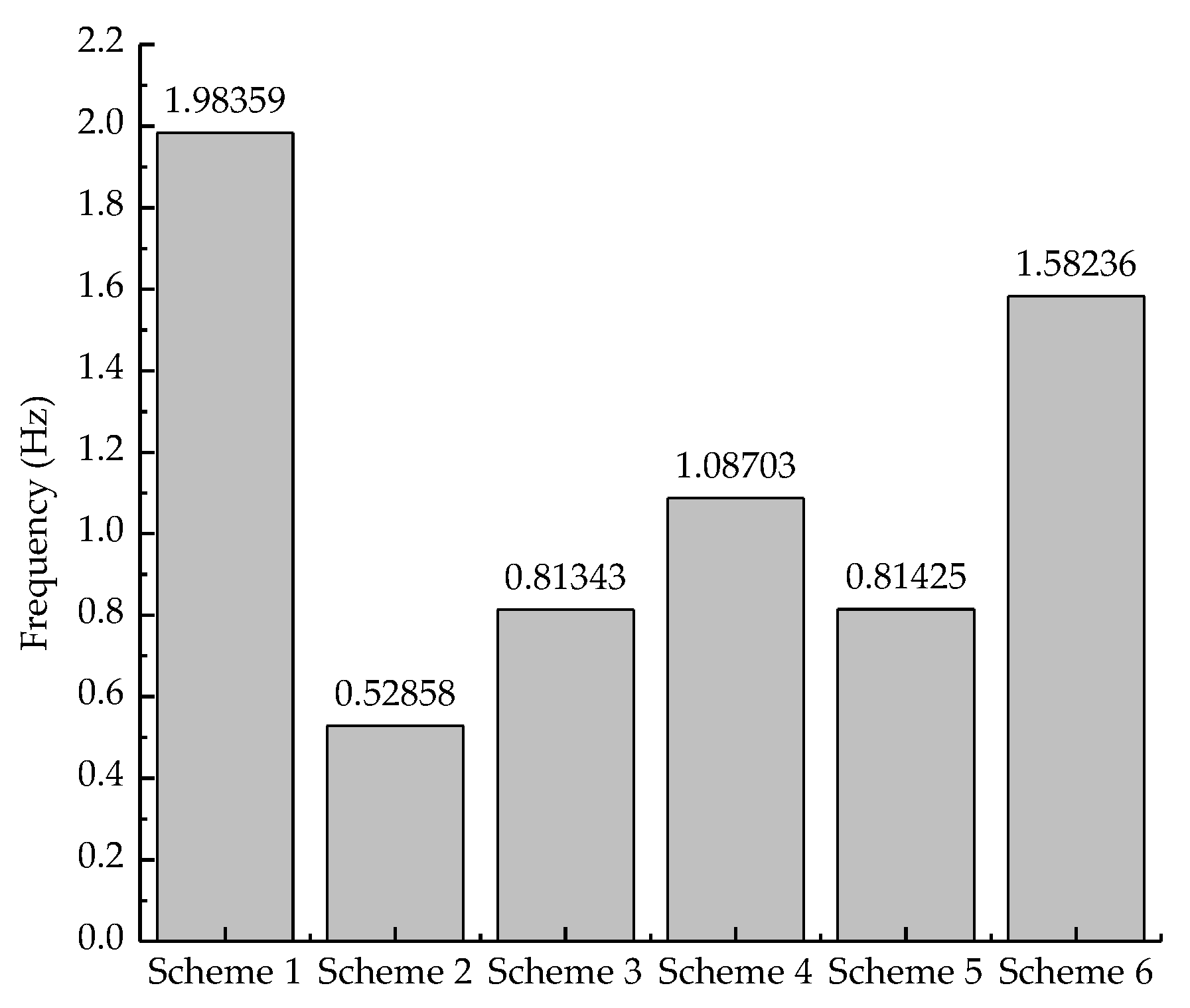
4.1.1. Comparison of Vibration Modes and Frequencies

The first four lateral vibration modes of the bridge with different layout schemes of the buffers were illustrated in Table 3, and a comparison of the fundamental frequency of each layout scheme is exhibited in Figure 9. From Table 3, we noted that the first four lateral vibration modes of each layout scheme are quite different because the buffers provide different lateral supports for the stiffening girder. The first lateral vibration mode of Scheme 1 and Scheme 6 is the lateral vibration of the main cables. The first lateral vibration mode of the other schemes is lateral bending of the stiffening girder. The main reason is that the lateral stiffness of the girder increased when all the towers and abutments provided lateral supports for the girder. The vibration of the main cables becomes easier than the lateral bending of the stiffening girder. In addition, the lateral bending mode of the towers is easily aroused under dynamic loads when the buffers are installed at the towers. Thus, the earthquake response of the towers becomes more notable.
As shown in Figure 9, the fundamental frequency of the bridge in Scheme 1 is the highest in these schemes for the reason that the CSG is fixed to each tower and abutment in lateral direction, which limits the vibration of the girder in the lateral direction under dynamic excitations. The installation of buffers also increases the lateral stiffness of the bridge. It is apparent that the fundamental frequency of the bridge increases with the increase in the number of buffers. The fundamental frequency of the bridge is only 0.5286 Hz in Scheme 2, which is installed with four buffers. The frequency reaches 1.5824 Hz in Scheme 6, which is installed with 10 buffers. The fundamental frequency of the bridge in Scheme 2 is only 64.5% of that in Scheme 5, and the fundamental frequency of the bridge in Scheme 3 is only 51.4% of that in Scheme 6. The lateral stiffness of the girder increases when the abutments provide lateral support for the girder, and the first lateral vibration mode of the bridge clearly changes.

4.1.2. Comparison of Internal Forces

The transverse moment of the bottom of the towers with different layout schemes of the buffers under five seismic waves is presented in Figure 10. The dynamic characterizations of bridge models and the power spectra causes the differences between the dynamic responses of the bridge under five seismic waves excitations. The maximal moment at the bottom of the side towers is 373,300 kN·m when the bridge was excited by the El Centro site wave and the installed four buffers of the bridge are between the two side towers and the stiffening girder. The main reason is that the inertial forces created by the vibration of the stiffening girder in an earthquake were mainly taken up by the side towers. Another reason is that the response spectrum of the El Centro record as shown in Figure 8 is larger than the values of other recorders near the period of the first vibration mode of Scheme 2. The maximal moment at the bottom of the middle tower in Scheme 4 is 621,700 kN·m when the bridge was excited by Taft Lincoln School record. For further investigating the effect of buffer locations on the seismic responses of the bridge, the results caused by the San Fernando Pacoima Dam record are discussed in detail.
As shown in Figure 10a, the transverse moment bending of the bottom of the side towers and middle tower in Scheme 2 is 171,800 kN·m and 21,360 kN·m, respectively. The transverse moment bending of the bottom of the middle and side tower in Scheme 3 are 169,500 kN·m and 250,200 kN·m, respectively. Compared with Scheme 3, the sum of the transverse moment of the bottom of the three towers in Scheme 2 is only 46.0% that of Scheme 3. Moreover, the sum of the transverse moment of the bottom of the three towers in Scheme 1 and Scheme 6 is much larger. This finding suggests that the larger the number of lateral buffers, the larger the lateral fundamental frequency becomes and the higher the seismic responses that the towers are subjected to. A larger lateral stiffness of the bridge is indicative of a closeness of the lateral fundamental frequency to the predominant period of the seismic waves. Thus, the bridge is expected to be subjected to significant earthquake action.
However, there is a distinct result in Figure 10a. The transverse moment of the bottom of the side towers in Scheme 2 is larger than that in Scheme 5. The transverse moment of the bottom of the side towers in Scheme 3 is larger than that in Scheme 6. Therefore, the transverse moment does not seem to conform to the above rules because lateral earthquake forces dispersed when the added buffers are installed at the abutments. The seismic design of abutments is a new problem to settle. Certainly, the vibration state of the side towers is more dangerous. Figure 11 depicts the lateral displacement on the top of the side towers with different layout schemes of buffers. The lateral displacement of the top of the side towers in Scheme 5 and Scheme 6 is four times that in Scheme 2 and Scheme 3, respectively, for the reason that the lateral bending mode of the side towers occurs in a low-order vibration mode, as listed in Table 3.
As shown in Figure 10, the sum of the transverse moment of the bottom of the three towers in Scheme 2 is the lowest, and the lateral deformation of the side towers in Figure 11 is also small. Thus, to control the transverse slip of the CSG and to decrease the seismic responses of the towers, the lateral buffer should be placed between the side towers and the stiffening girder.

4.2. Effect of Damper Location

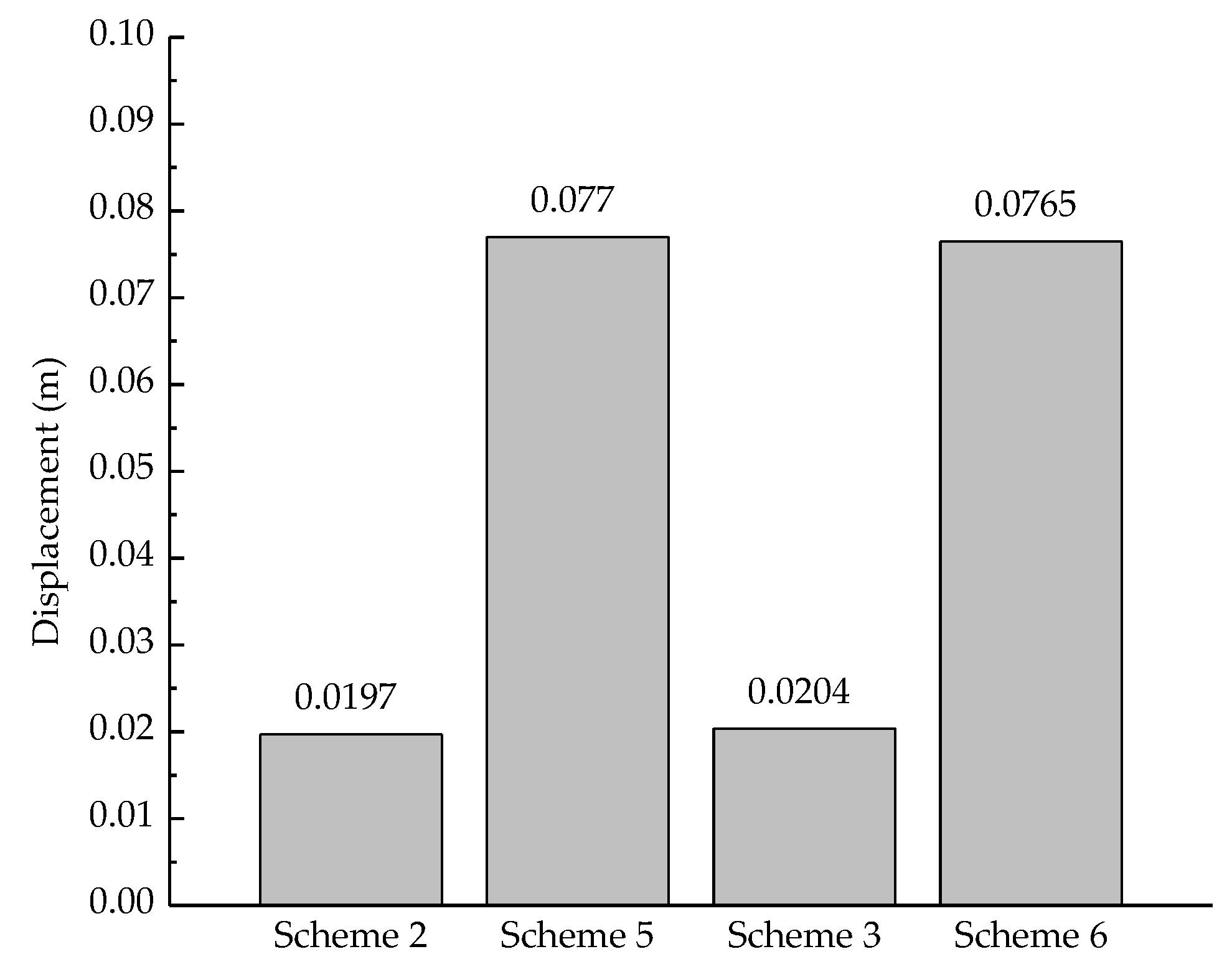
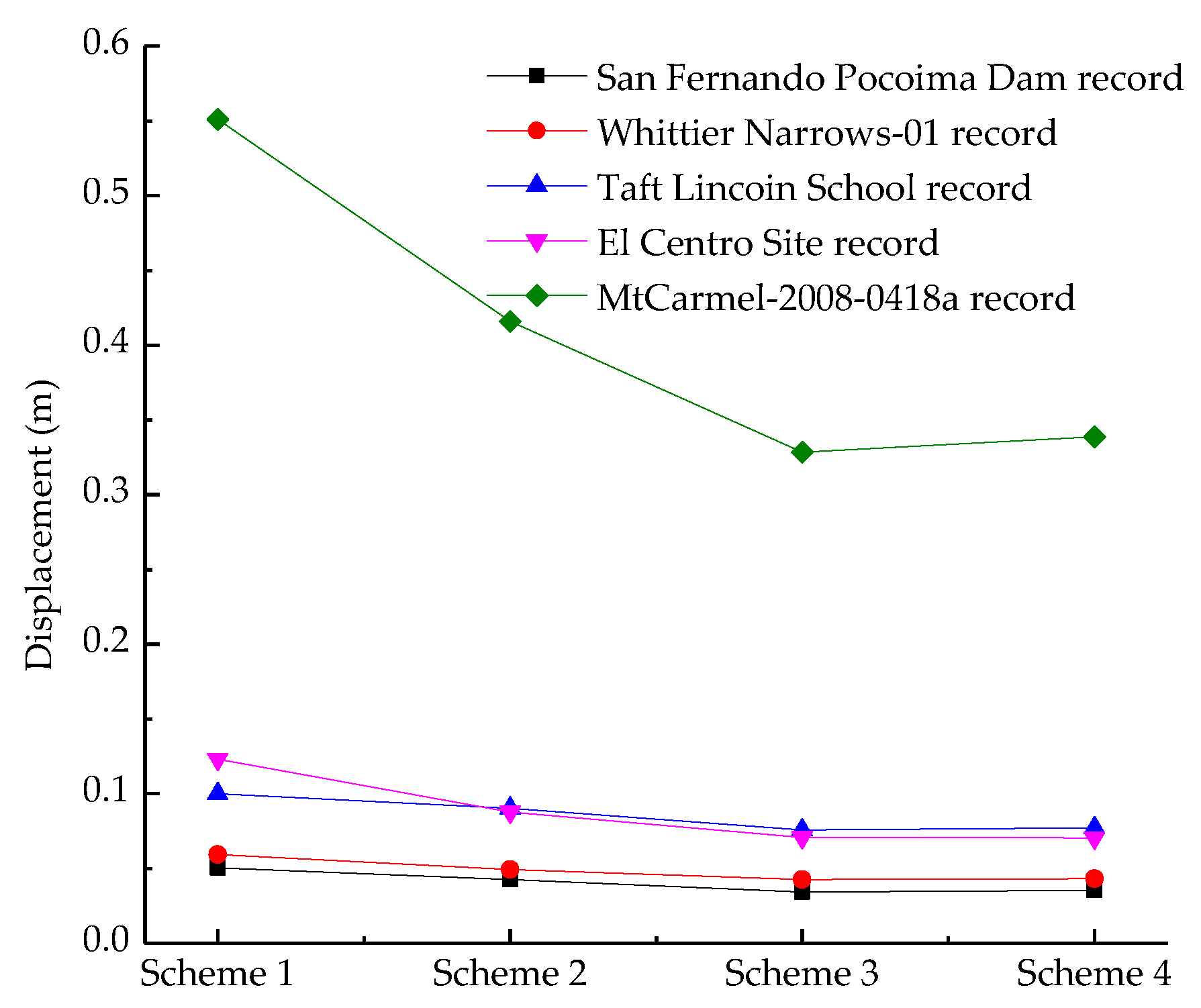
4.2.1. Comparison of the Longitudinal Deformation

The beam-end longitudinal displacements with the four passive-energy dissipating schemes under different seismic waves are presented in Figure 12. One striking result to emerge from the data is that the viscous dampers have a strong ability to reduce the bridge deformation and seismic responses of the towers. From the data in Figure 12, the longitudinal displacement responses under the five seismic records are deeply affected by the installation of the viscous dampers. The maximum beam-end longitudinal displacement decreases from 0.0505 to 0.0354 m, from 0.0594 m to 0.0430 m, from 0.0999 m to 0.0772 m, from 0.1230 m to 0.0706 m, and from 0.5509 m to 0.3386 m, respectively. The average decrease of beam-end longitudinal deformation under the five seismic recorders reaches 32.3%, which is caused by the installation of the viscous dampers.
Another distinct result from Figure 12 is that the energy dissipation efficiency of one viscous damper steadily reduces with an increasing number of viscous dampers. According to the data, the maximum beam-end longitudinal displacements with the different schemes (Scheme 1, Scheme 2, Scheme 3, and Scheme 4) for the San Fernando Pacoima Dam record are 0.0505 m, 0.0427 m, 0.0343 m, and 0.0354 m, respectively, and the damping effect reaches 15.4%, 32.1%, and 30.0%, respectively. The damping effect of Scheme 3 is close to or even better than that of Scheme 4. Thus, it is not the case that the larger the number of dampers is, the better the shock absorption. Moreover, the vibration law of the beam-end longitudinal displacements under other seismic waves is similar to that of the San Fernando Pacoima Dam record.

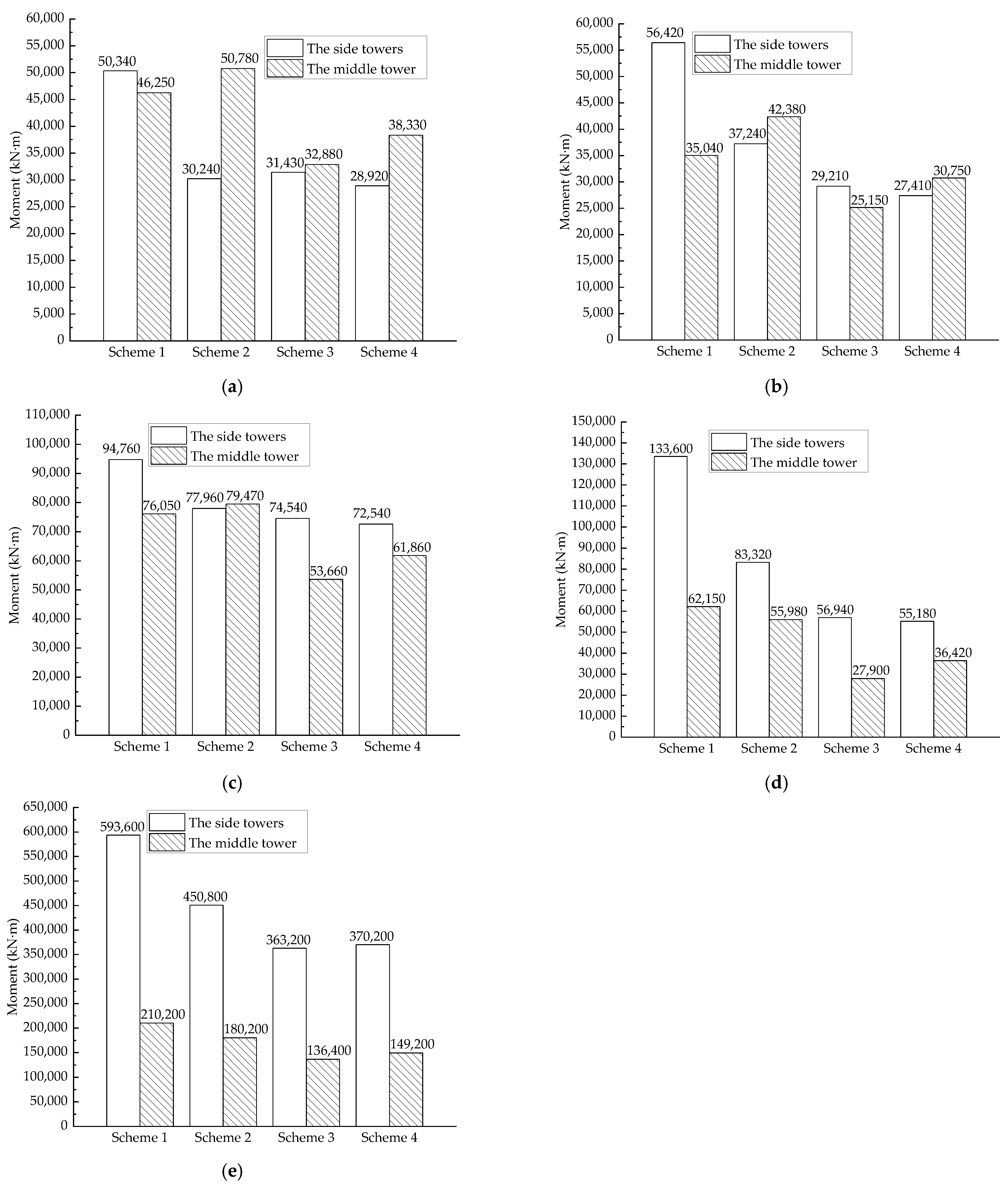
4.2.2. Comparison of Internal Forces

The longitudinal moments of the bottom of the towers with different layout schemes of the viscous dampers under five seismic waves were presented in Figure 13. According to the data in Figure 13a–e, it is apparent that the viscous dampers effectively dissipate the seismic responses of the towers. Taking the San Fernando Pacoima Dam record as an example, the maximal longitudinal moment of the side towers gradually decreases from 50,340 kN·m in Scheme 1 to 35,570 kN·m in Scheme 4, and the final damping effect reaches 29.3%. The maximal longitudinal moment of the middle towers decreases from 46,250 kN·m in Scheme 1 to 38,330 kN·m in Scheme 4, and the final damping effect reaches 17.1%.
However, the damping effect of the viscous dampers on the longitudinal moment of the towers is not as remarkable as that on the beam-end lateral displacement. One reason is that most of the earthquake force that a girder is subjected to is directly transferred to the central part of the tower when the viscous dampers provide longitudinal supports to the girder. The seismic responses of the tower installed with the dampers are augmented under the forces transferred by the dampers from the main girder. For example, the maximal longitudinal moment of the middle towers in Scheme 4 is larger than that in Scheme 3, as shown in Figure 13. Another reason is that the damping effect of the viscous dampers reduces the earthquake energy that the bridge is subjected to.
Moreover, the longitudinal moment of the side towers is larger than that of the middle tower when the bridge has no dampers, as shown in Figure 13. Thus, the weak structures of this type of SASB subjected to an earthquake comprise the side towers. Reasonable seismic control schemes in the longitudinal direction should balance the force of the side towers and the middle tower.

5. Summary and Conclusions

In this study, a time-history analysis method was employed to perform the dynamic characteristic analysis of a three-tower SASB with a CSG depending on the Midas/Civil software. The main objective of the current research was to compare the effect of buffer and damper locations on the dynamic response of this type of bridge. The following conclusions can be drawn from the seismic studies of the SASB:
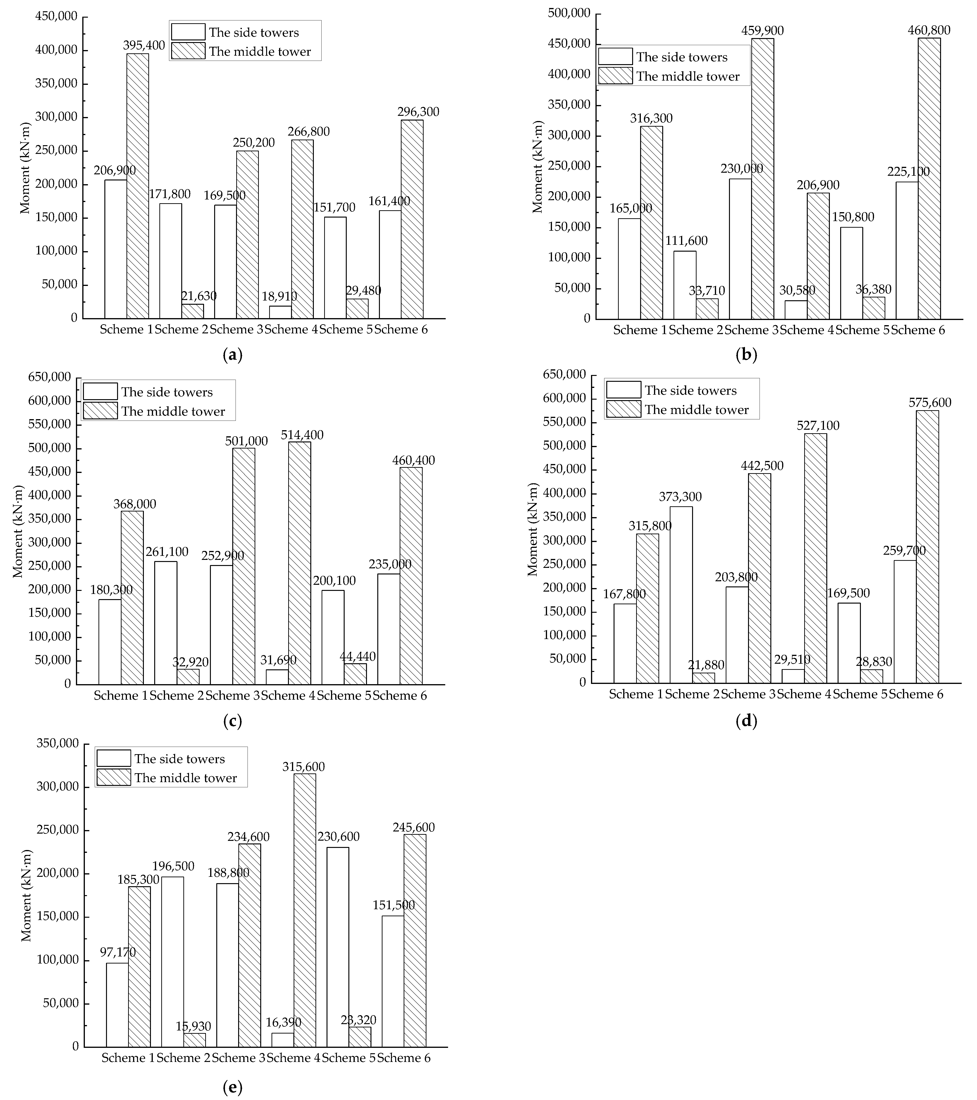
  • Part of the lateral seismic design was aimed at investigating the effect of buffer location on the dynamic response of the three-tower SASB. The installation locations of the buffers have a marked impact on the first lateral mode of the bridge. Increasing the number of the lateral buffers increases the lateral frequency and leads to larger seismic responses of the towers when the bridge is suffering earthquake loads.
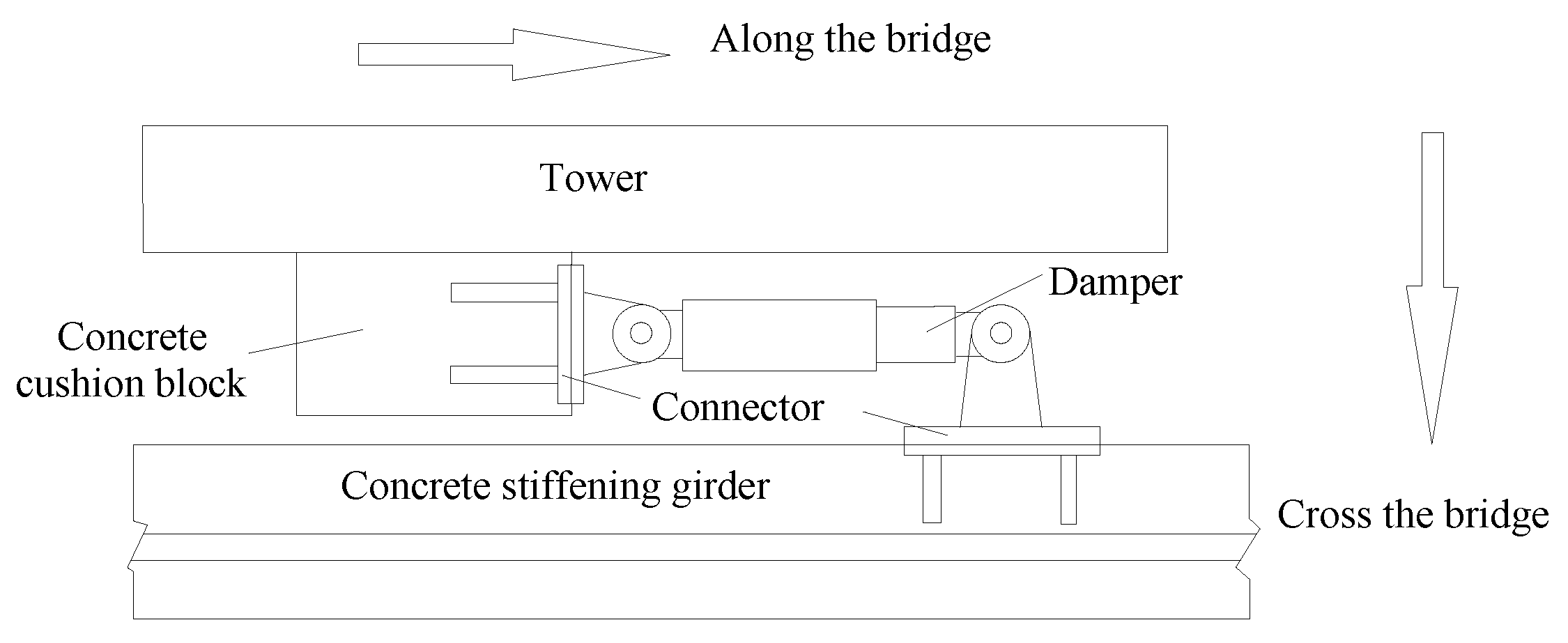
  • Part of the longitudinal seismic design was aimed at selecting the optimal layout scheme of the viscous damper for the three-tower SASB with a CSG. The weakness structure of the bridge under longitudinal earthquake waves is the side towers when the bridge has no dampers. The viscous dampers assembled between the towers and the main girder drastically reduce the moments of the towers in longitudinal direction. Installation of the dampers in a reasonable way can balance the internal force distribution in the side towers and the middle tower.
  • Comparing the two-part results, to effectively increase the seismic performance of SASBs with three towers, mounting buffers between the side towers and the main girder of SASBs is an appropriate scheme. The installation of the dampers between the columns of the middle tower and the stiffening girder is better than other seismic control schemes. In addition, the number of viscous dampers in this scheme is more economical than the other schemes.
Overall, the conclusions obtained through numerical simulation are relevant references for the seismic design of a three-tower SASB with a CSG.

Author Contributions

Conceptualization, S.P.; software, W.Z.; validation, S.P.; investigation, K.T. and S.F.; data curation, K.T.; writing—original draft preparation, K.T.; writing—review and editing, S.P., S.F. and W.Z.; revising—J.W. and S.F. All authors have read and agreed to the published version of the manuscript.

Funding

This research was funded by the Scientific Research Fund of China Scholarship Council and National Natural Science Foundation of China (Grant No. 51678110).

Data Availability Statement

Not applicable.

Conflicts of Interest

The authors declare no conflict of interest.

References

  1. Abdel-Ghaffar, A.M.; Rubin, L.I. Torsional earthquake response of suspension bridges. J. Eng. Mech. 1984, 110, 1467–1484. [Google Scholar] [CrossRef]
  2. Abdel-Ghaffar, A.M.; Scanlan, R.H. Ambient vibration studies of golden gate bridge: II. Pier-tower structure. J. Eng. Mech. 1985, 111, 483–499. [Google Scholar] [CrossRef]
  3. Abdel-Ghaffar, A.M.; Scanlan, R.H. Ambient vibration studies of golden gate bridge: I. Suspended structure. J. Eng. Mech. 1985, 111, 463–482. [Google Scholar] [CrossRef]
  4. Abdel-Ghaffar, A.M.; Rubin, L.I. Lateral earthquake response of suspension bridges. J. Struct. Eng. 1984, 109, 664–675. [Google Scholar] [CrossRef]
  5. Celebi, M. Golden gate bridge response: A study with low-amplitude data from three earthquakes. Earthq. Spectra 2012, 28, 487–510. [Google Scholar] [CrossRef]
  6. Bahbouh, L.; Yamada, H.; Katsuchi, H.; Sasaki, E.; Theeraphong, C. The behaviour of Akashi Kaikyo Bridge under multi support seismic excitation for low frequency motions. WIT Trans. Built Environ. 2009, 104, 345–355. [Google Scholar]
  7. Xiao, L.; Li, C.J.; Qiang, S.Z. Influence of Soil-Pile-Structure interaction on seismic response of long span suspension bridge. In Proceedings of the Integrated Transportation Systems—Green Intelligent Reliable (ICCTP 2010), Beijing, China, 4–8 August 2010; pp. 3147–3156. [Google Scholar]
  8. Arzoumanidis, S.; Shama, A.A.; Marlow, S.J.; Orsolini, G.O. The New Tacoma Narrows Suspension Bridge: Critical issues in seismic analysis and design. In Proceedings of the Structures 2005, New York, NY, USA, 20–24 April 2005; pp. 1–12. [Google Scholar]
  9. Gao, Y.; Yuan, W.C.; Zhou, M.; Cao, X.J. Seismic Analysis and Design Optimization of a Self-Anchored Suspension Bridge. In Proceedings of the Lifeline Earthquake Engineering in a Multihazard Environment (TCLEE2009), Oakland, CA, USA, 28 June–1 July 2009; pp. 153–164. [Google Scholar]
  10. Okuda, M.; Fukunaga, S.; Endo, K. Seismic design and seismic performance retrofit study for the Akashi Kaikyo Bridge. Bridge Struct. Assess. Des. Constr. 2009, 5, 109–118. [Google Scholar] [CrossRef]
  11. Vader, T.S.; Mcdaniel, C.C. Influence of dampers on seismic response of cable-supported bridge towers. J. Bridge Eng. 2007, 12, 373–379. [Google Scholar] [CrossRef]
  12. Murphy, T.P.; Collins, K.R. Retrofitting suspension bridges using distributed dampers. J. Struct. Eng. 2004, 130, 1466–1474. [Google Scholar] [CrossRef]
  13. Wang, H.; Zhou, R.; Zong, Z.H.; Wang, C.; Li, A.Q. Study on seismic response control of a single-tower self-anchored suspension bridge with elastic-plastic steel damper. Sci. China Technol. Sci. 2012, 55, 1496–1502. [Google Scholar] [CrossRef]
  14. Song, X.M.; Dai, G.L.; Zeng, Q.Y. Seismic response analysis and control of self-anchored suspension bridge. J. Cent. South Univ. Sci. Technol. 2009, 40, 1079–1085. [Google Scholar]
  15. Xu, Z.; Yang, Y.; Miao, A. Dynamic analysis and parameter optimization of pipelines with multidimensional vibration isolation and mitigation device. J. Pipeline Syst. Eng. Pract. 2021, 12, 04020058. [Google Scholar] [CrossRef]
  16. He, Z.; Huang, X.; Xu, Z.; Shi, Q.; Guo, Y.; Kim, J. Experimental study on seismic performance of prefabricated viscoelastic damping bolted joints. Eng. Struct. 2022, 256, 113933. [Google Scholar] [CrossRef]
  17. He, Z.; Xu, Z.; Xue, J.; Jing, X.; Dong, Y.; Li, Q. Experimental and mathematical model of a novel viscoelastic bio-inspired multi-dimensional vibration isolation device. Mech. Adv. Mater. Struct. 2022. [Google Scholar] [CrossRef]
  18. Deng, Y.L.; Peng, T.B.; Li, J.Z.; Ji, L. Study on dynamic characteristic and aseismic performance of a long-span triple-tower suspension bridge. J. Vib. Shock 2008, 27, 105–110. [Google Scholar]
  19. Wang, H.; Zou, K.G.; Li, A.Q.; Jiao, C.K. Parameter effects on the dynamic characteristics of a super-long-span triple-tower suspension bridge. J. Zhejiang Univ. Sci. A Appl. Phys. Eng. 2010, 11, 305–316. [Google Scholar] [CrossRef]
  20. Zhang, J.W.; Guo, W.H.; Xiang, C.Q. Dynamic characteristics analysis and parametric study of a super-long-span triple-tower suspension bridge. Appl. Mech. Mater. 2012, 256–259, 627–1633. [Google Scholar] [CrossRef]
  21. Jiao, C.K.; Li, A.Q.; Wang, H. Seismic response control of three-towers suspension bridge. J. Vib. Meas. Diagn. 2011, 31, 156–161. [Google Scholar]
  22. Wang, H.; Li, J.; Tao, T.Y.; Wang, C.F.; Li, A.Q. Influence of apparent wave velocity on seismic performance of a super-long-span triple-tower suspension bridge. Adv. Mech. Eng. 2015, 7, 1687814015589464. [Google Scholar] [CrossRef]
  23. Fang, Z.Z.; Zhang, C.; Chen, Y.J. Dynamic characteristics analysis and parametric study of self-anchored suspension bridge with three towers. J. Earthq. Eng. Eng. Vib. 2010, 30, 97–102. [Google Scholar]
  24. Chen, Y.J.; Fang, Z.Z.; Zhang, C. Research on main saddle’s restriction of self-anchored suspension bridge with three towers. J. Fuzhou Univ. Nat. Sci. Ed. 2011, 39, 428–433. [Google Scholar]
  25. Zhang, C.; Fang, Z.Z. The influence law of longitudinal constraints between tower and girder on seismic performance of self-anchored suspension bridge with multi-tower. J. Fuzhou Univ. Nat. Sci. Ed. 2013, 41, 539–543. [Google Scholar]
  26. Zhang, C.; Huang, K. Influence law of tower stiffness on vertical stiffness of three-tower self-anchored suspension bridge based on frequency formulas. J. Vibroeng. 2014, 16, 2909–2920. [Google Scholar]
  27. Tian, K.; Pan, S. Research on Parameters of Damping Device for Three-tower Concrete Self-anchored Suspension Bridge. North. Commun. 2018, 5, 1–6. [Google Scholar]
Figure 1. General layout of the bridge (unit: m).
Buildings 13 00081 g001
Figure 2. Cross-section of the box concrete stiffening girder (unit: cm).
Buildings 13 00081 g002
Figure 3. Installation and composition of the lateral seismic block.
Buildings 13 00081 g003
Figure 4. Six different layout schemes of the buffers.
Buildings 13 00081 g004
Figure 5. Installation of a longitudinal viscous damper.
Buildings 13 00081 g005
Figure 6. Three different damper layout schemes.
Buildings 13 00081 g006
Figure 7. Finite element model.
Buildings 13 00081 g007
Figure 8. Spectra of the five earthquake records (N-S).
Buildings 13 00081 g008
Figure 9. Fundamental frequencies of the bridge in different schemes.
Buildings 13 00081 g009
Figure 10. Comparison of the transverse tower shaft moment with different layout schemes of the buffer. (a) San Fernando Pacoima Dam record; (b) Whittier Narrows-01 record; (c) Taft Lincoln School record; (d) El Centro Site record; (e) MtCarmel-2008-0418a record.
Buildings 13 00081 g010
Figure 11. Comparison of the lateral displacement at the top of the side towers.
Buildings 13 00081 g011
Figure 12. Beam-end longitudinal displacement.
Buildings 13 00081 g012
Figure 13. Comparison of the longitudinal tower shaft moment with different layout schemes of the viscous dampers. (a) San Fernando Pacoima Dam record; (b) Whittier Narrows-01 record; (c) Taft Lincoln School record; (d) El Centro Site record; (e) MtCarmel-2008-0418a record.
Buildings 13 00081 g013
Table 1. Material data of the example bridge.
MaterialTypeDBE
(KN/m2)
vα
(1/[C])
ρ
(KN/m3/g)
CablessteelWire17702.05 × 10+080.31.20 × 10−058
SuspenderssteelWire16702.05 × 10+080.31.20 × 10−058
Prestressed reinforcementsteelStrand18601.95 × 10+080.31.20 × 10−058
ConcreteconcreteC553.55 × 10+070.21.00 × 10−052.55
Steel barsteelQ3452.06 × 10+080.31.20 × 10−057.85
Table 2. Site classes of each record.
RecordsComponent
YearVS (m/s)Site Classes
San Fernando Pacoima Dam record19712016.13Hard rock with measured shear wave velocity, VS > 1500 m/s
Whittier Narrows-01 (Pasadena -CIT Kresge Lab) record1987969.07Rock with 760 m/s < VS ≤ 1500 m/s
Taft Lincoln School record1952385.43Very dense soil and soft rock with 360 m/s < VS ≤ 760 m/s
El Centro Site record1940213.44Stiff soil with 180 m/s ≤ VS ≤ 360 m/s
MtCarmel-2008-0418a record2008160.00Soil profile with VS < 180 m/s
Table 3. The first four lateral vibration modes of the bridge with different layout schemes.
Scheme TypeFirst Order ModeSecond Order ModeThird Order ModeFourth Order Mode
Scheme 1 Buildings 13 00081 i001 Buildings 13 00081 i002 Buildings 13 00081 i003 Buildings 13 00081 i004
Symmetric lateral vibration of the main cablesAntisymmetric lateral vibration of the main cablesSymmetric lateral vibration of the main cablesAntisymmetric lateral vibration of the main cables
Scheme 2 Buildings 13 00081 i005 Buildings 13 00081 i006 Buildings 13 00081 i007 Buildings 13 00081 i008
Symmetric lateral bending of the CSGAntisymmetric lateral bending of the concrete stiffening girderSymmetric lateral bending of the CSG accompanied by lateral bending of the side towersAntisymmetric lateral vibration of the main cables accompanied by lateral bending of the side towers
Scheme 3 Buildings 13 00081 i009 Buildings 13 00081 i010 Buildings 13 00081 i011 Buildings 13 00081 i012
Symmetric lateral bending of the CSG accompanied by lateral bending of the three towersAntisymmetric lateral bending of the CSG accompanied by a lateral bending of the side towerSymmetric lateral bending of the CSG accompanied by lateral bending of the side towersAntisymmetric lateral vibration of the main cables accompanied by the lateral bending of the side towers
Scheme 4 Buildings 13 00081 i013 Buildings 13 00081 i014 Buildings 13 00081 i015 Buildings 13 00081 i016
Antisymmetric lateral bending of the CSGSymmetric lateral bending of the CSGSymmetric lateral vibration of the main cables accompanied by lateral bending of the middle towerAntisymmetric lateral vibration of the main cables
Scheme 5 Buildings 13 00081 i017 Buildings 13 00081 i018 Buildings 13 00081 i019 Buildings 13 00081 i020
Symmetric lateral bending of the CSG accompanied by lateral bending of the side towersAntisymmetric lateral vibration of the main cables accompanied by the lateral-bending of the side towersSymmetric lateral vibration of the main cablesSymmetric lateral vibration of the main cables
Scheme 6 Buildings 13 00081 i021 Buildings 13 00081 i022 Buildings 13 00081 i023 Buildings 13 00081 i024
Symmetric lateral vibration of the main cables accompanied by lateral bending of the three towersAntisymmetric lateral vibration of the main cables accompanied by the lateral bending of the side towersSymmetric lateral vibration of the main cablesAntisymmetric lateral vibration of the main cables
Disclaimer/Publisher’s Note: The statements, opinions and data contained in all publications are solely those of the individual author(s) and contributor(s) and not of MDPI and/or the editor(s). MDPI and/or the editor(s) disclaim responsibility for any injury to people or property resulting from any ideas, methods, instructions or products referred to in the content.

