1. Introduction to Storm-Water Detention Assembly (SDA)
Storm-water related events are becoming more frequent and intense as one of the consequences of climatic changes across the globe, negatively impacting buildings and urban infrastructure, both financially and socially. To mitigate these impacts in dense urban areas, low impact development (LID) strategies continue to be developed and adopted [
1,
2,
3,
4,
5,
6,
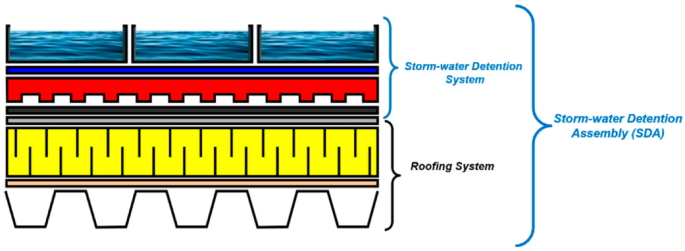
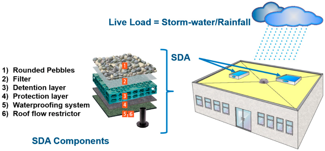
7]. Roof surfaces constitute a significant portion of urban impermeable cover. This has created opportunities to develop strategies to reduce the impact of the impermeable cover of low-sloped roofs. One way to control the impact of storm-water related events is to use these surfaces of low-sloped roofs by implementing a Storm-water Detention Assembly (SDA), also commonly known as a “blue roof” (
Figure 1).
The SDA approach is based on the principle of temporarily capturing and detaining storm-water on the roof and then, either allowing it to evaporate, be stored for re-use, or released over time to reduce the peak flow into the municipal storm-water system. The idea behind this approach is to mimic the hydrology of the building site before impermeable surfaces were constructed on it. Several jurisdictions are already encouraging the use of SDA as a low impact development (LID) strategy to manage storm-water run-off from buildings. New York’s Storm-water Design Construction Guidelines allows for the use of SDA with controlled flow devices for this purpose [
8,
9,
10,
11,
12,
13,
14]. The Ontario Storm-water Management Planning and Design Manual also recognizes storm-water control from rooftops. It identifies approaches that divert water from roof leader to ponding area and roof leader to soak away pits as acceptable storm-water management practices [
10,
11,
12,
13,
14,
15]. Essentially the rooftops are designed with system that can release rainwater gradually into the storm-water system, and/or to facilitate its infiltration into the ground.
Over the last two decades, vegetated roofing assemblies (VRA) have been an option to mitigate the impermeability of rooftops. More recently the SDA is finding favor in the roofing community and municipalities due to limitations of VRA such as problems with accurate performance evaluation, structural capacity, and long-term performance impacted by lack of maintenance. The focus of this paper is on SDA. The successful use of SDA requires harmonized guideline for its design, construction, and maintenance. At present, such guidelines are not available to cover the three mentioned areas (design, construct, and maintenance). Some of the requirements that pertain to the design of SDA in the building codes are also inconsistent among jurisdictions.
The SDA includes the low-slope roofing system, the water detention components, and the drainage system with the flow control devices. Storm-water captured from precipitation is either ponded as open water or absorbed and stored in a granular medium arranged on the rooftop. SDA may use flow restrictors which slow down the flow of water to the drains. The flow control devices direct the slow discharge of the detained water, effectively slowing down the rate of the volume of rainfall runoff from a site. The SDA can be characterized by how the roof can detain storm-water and can be categorized as Roof-Integrated Design (RID) or Modular Tray Design (MTD) [
16,
17,
18,
19,
20].
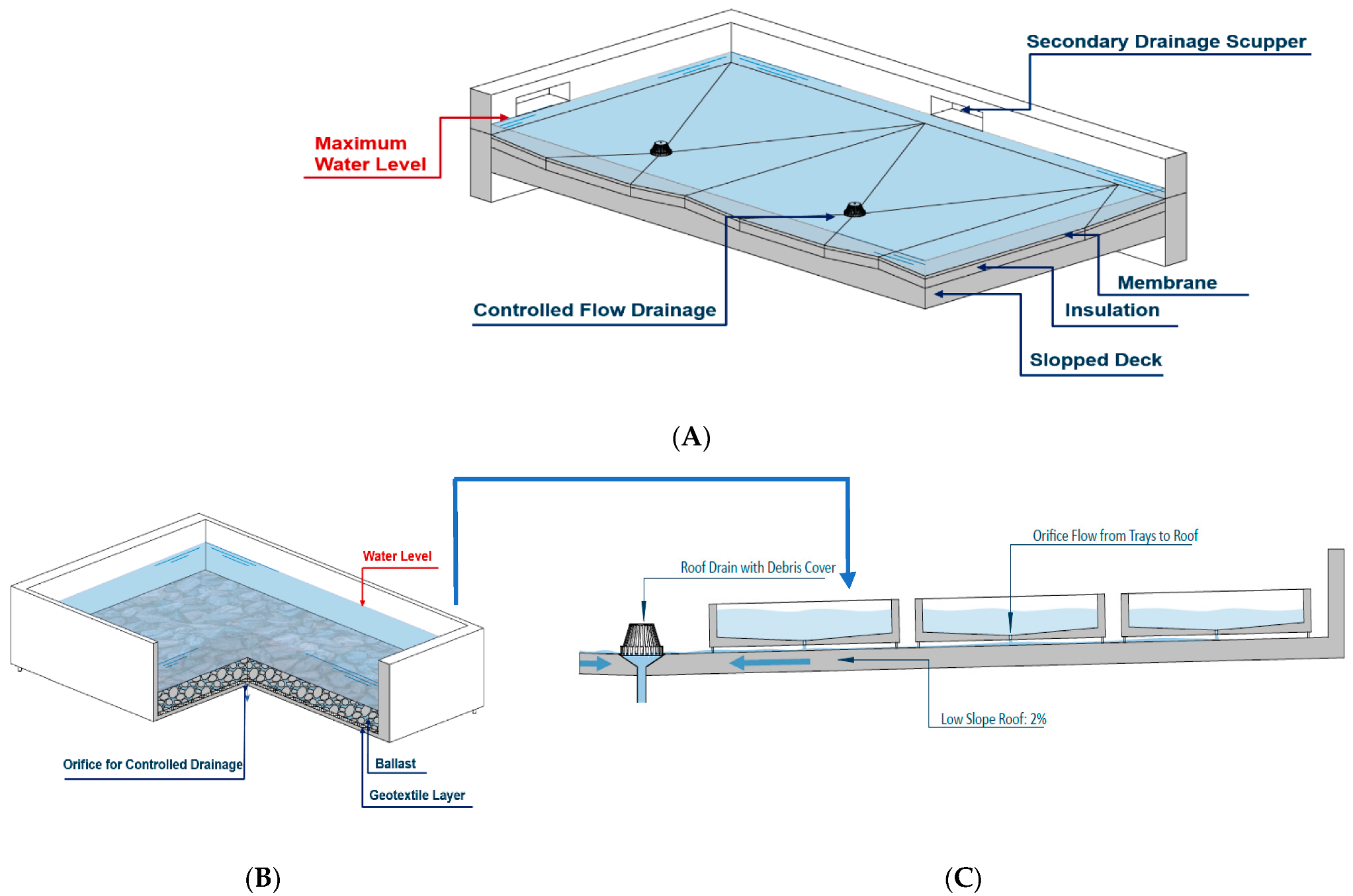
The Roof-Integrated Design (RID) uses the roof itself as a big ponding device, where storm-water is accumulated on the roofing system (
Figure 2A). Under the umbrella of RID, checked dams and modified drainage inlets are both ways to achieve water ponding on the entire roof. Checked dams are typically semi-permeable vertical panels that create designed ponding between such planes and the roof slope. The orifice on the vertical panels slows the flow rate of the storm-water into the main roof drainage system. Modified drainage inlets are designed to replace the conventional roof drains to achieve a slower flow rate into the leader pipe. RID can be either active or passive. In an active system, the drains can incorporate valves that can be remotely controlled. A passive system usually involves a weir installed as part of the drainage system. Weirs typically have an orifice that reduces flow rate compared to a drain without it. In the RID system, the waterproofing membrane needs to withstand larger volume of ponding water, for longer periods of time, than in a conventional roofing system. Detaining (ponding) water directly on the roofing membrane needs to consider many factors in order to ensure that the main functionality of the roofing system is not compromised [
21,
22,
23,
24,
25,
26,
27]. For example, if there is equipment present on the roof, it needs to be placed on high enough curbs that are at least higher than the designed ponding depth of the roof.
The Modular Tray Design (MTD) is a tray-based system (mostly using plastic material) that contains porous media and controlled drainage from weep holes at the bottom of the tray (
Figure 2B). These trays are the primary storm-water detention units. They can be selectively installed on the available surface of the roof (
Figure 3B). With the MTD, the equipment and structural configurations require less of an intervention compared to RID. This method can also limit water detention to specific parts of the roof where structural loading is an issue [
28,
29,
30]. Since the detention process is happening at the tray level, its detention capacity can be independent of the waterproofing system, making it the more consistent and effective storm-water detention roof design for retrofitting [
31,
32,
33,
34,
35]. Compared to MTD, the RID requires less material. However, the roofing system will potentially require more intervention to be able to deal with water detention. Therefore, RID may be more suitable for new constructions where all design aspects can be implemented prior to the construction of the roofing system. The MTD system, on the other hand, can be an effective retrofitting option or an add-on, as it does not require the roof to be remodeled/upgraded.
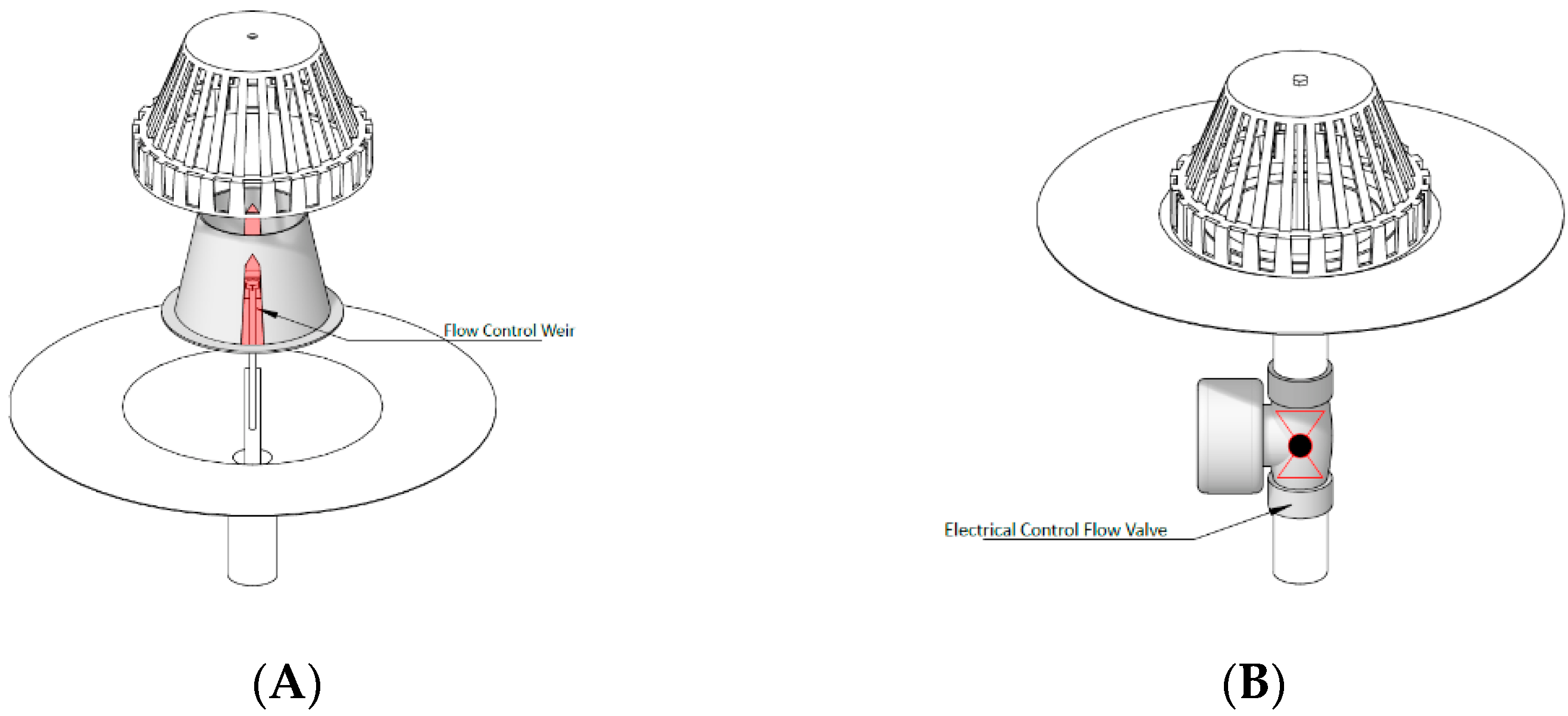
As previously mentioned, SDA can have a Passively Controlled System (PCS) and Actively Controlled System (ACS) to regulate water detention. The PCS uses weirs, orifice plates, roof dams, roof checks, or hydraulic regulators to control water discharge. These passive flow control devices are generally less expensive but are less customizable when adapting to different site requirements (
Figure 3A).
The ACS, on the other hand, provides the possibilities of control that can be programmed using Artificial Intelligence (AI). The use of AI to control detention provides significant possibilities to mitigate risks, to deal with a variety of site conditions, and also the possibility to scale rooftop storm-water management to multiple buildings. In the ACS, sensors and valves can be used to monitor and control water detention. The actuation of the valves can be controlled either by manually set timer, or by electronically monitored devices of water depth or weather conditions [
36,
37,
38,
39,
40]. Using AI, these valves can also be integrated with predictive weather algorithms to achieve smart sensors that can accommodate the complex weather phenomenon (
Figure 3B). For both the PCS and ACS installed in an SDA, maintenance needs to be specified and performed regularly to ensure the functionality and performance of the system, while avoiding potential damage to the underlying roof assembly.
SDA has multiple benefits regarding to storm-water management: (I) reducing peak flow and water volume run-off during intense rainfall events, mitigating flood risk, and reducing the possible sewer overflows and erosion in receiving streams; (II) reusing storm-water (e.g., flushing toilets, irrigating lawns and gardens) or evaporation. This can reduce load on the storm-water infrastructure, help maintain water balance, reduce urban heat island effects, and reduce energy for cooling the building; and (III) utilizing the vast spaces of the unused surfaces of low-sloped roofs in dense urban areas which lack adequate storm-water infrastructure [
41,
42,
43,
44,
45,
46,
47,
48,
49,
50,
51,
52,
53,
54].
A few existing examples of SDA across the world are shown in
Table 1. The buildings in these examples have the low-sloped roof (less than 2%) and the intention has been to monitor the performance of the SDA, including evaluating different types of SDA. Data from peak flow reduction show that MTD has a consistent performance compared to the passive SDA methods. Peak flow reduction refers to the amount of storm-water that could be stored in a system and thus reducing the discharge flow rate and mitigate urban flooding. The United States Environmental Protection Agency Storm-Water Management Model (US EPA SWMM) is a dynamic rainfall–runoff simulation to model the hydrology in a system and also has the capacity to quantify and model low impact development (LID) scenarios and can calculate the peak flow reduction in a system.
2. Characterizing SDA Performance Using Hydrographs
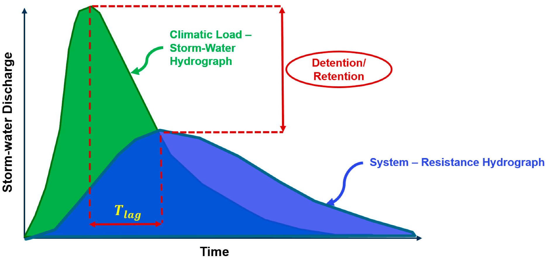
A hydrograph curve can be used to assess the storm-water detention capacity of an SDA (
Figure 4). A specific storm event can be shown as climatic load hydrograph. The SDA system hydrograph shows the discharge rate. The detention capacity of the SDA can be taken as the reduction in peak discharge of the storm event relative to the SDA system resistance. The peak flow of the SDA system occurs over a longer period than the peak flow of the storm. This is considered the lag. The area between the storm hydrograph that represents the climatic load and SDA system hydrograph provides the retention/detention volume.
The maximum detained volume occurs when the two hydrographs intersect [
13,
51]. For vegetated roofing assembly (VRA), known as green roof, the maximum detention depends on the soil composition (organic vs. inorganic rate), the level of soils’ saturation before the rain event, plants’ type, and evapotranspiration rate and drain system, whereas for the SDA, the maximum detention depends on the characteristics of the tray in the MTD approach and the roof drainage basin and drainage characteristics in the RID approach. In the SDA, the aim is to increase the storm-water detention to mitigate urban flooding or control storm-water flow.
The storm-water detention lag (
Tlag) is calculated with metrics related to changes in magnitude or discharge time (Equation (1)). Detention increases with a slower discharge.
The volumetric water storage referred to as detention capacity (
DET), quantified in percent, is the volume of storm-water detained over a period of time relative to the volume of storm-water event (Equation (2)).
A decrease in the discharge rate will enhance the detention volume. For the SDA application, the maximum stored volume depends on roofing storage volume in a RID system and the capacity of the tray in MTD. This will depend on the design of each system. The objective is to optimize the storm-water detention and rain capture to mitigate storm-water run-off and urban flooding by designing the SDA in such a way that its hydrograph is flattened and extended in time within the constraints of roofing structural load and waterproofing membrane capabilities [
51,
52,
53,
54,
55,
56,
57,
58,
59,
60,
61]. Accordingly, three factors need to be closely considered and determined for a successful design and functioning of the SDA as follows:
(I) The climatic load determination based on the buildings’ geographical location and roof orientation. The pattern of storm events intensity, duration, and frequency (IDF) will also need to be taken into account. For instance, the extreme rainfall depths for the specific site can be calculated according to information derived from the rainfall IDF curves plus a 40% increase to reflect climatic changes. It should be noted that storm and discharge rate need to be calculated simultaneously to better present SDA performance. The design capacity of the detention system should also be assessed. Should the detention value reach the maximum amount that the roof can store, then, the valves can be activated to release the excess storm into the municipal storm-sewer system or to another storage tank or ground level storage.
(II) The drainage requirements and specifications of flow control drains with hydraulic pressure calculations for piping, flashing, slow, or immediate release of harvested water over an extended period of time as stated in
Section 3.
(III) The structural requirements considerations such as capacity of the deck, roof assembly dead load, capacity of roof drainage/retention panel and storm-water storage, requirements of the waterproofing membrane, insulation, and other components as presented in
Section 4.
3. Current Codes and Guidelines on SDA Drain
3.1. Canadian Codes and Standards
In the National Plumbing Codes 2015 (NPC), there are two main components identified as part of the drainage system: the roof drain which means a fitting or device that is installed in the roof to permit storm-water to discharge into a leader, and a leader which means a pipe that is installed to carry storm-water from a roof to a storm building drain or sewer or other disposal units. The NPC states that minimum leader size for a roof drain is specified according to Table 2.4.10.11 based on the hydraulic load for a roof. Hydraulic load calculation is specified in 2.4.10.4.(1) as the product of the maximum 15 min rainfall from NBC in millimeters and the sum of the horizontal projection of the roof area and one-half of the area of the largest adjoining vertical surface. When flow control roof drains are used, hydraulic load is calculated with a 25-year rainfall intensity–duration–frequency curve from Environment Canada.
Therefore, the roof drainage requirements in the NPC 2015 clauses 2.4.10.4.(2) and (3) are particularly applicable for design of SDA. They stipulate minimum requirement for the use of flow control roof drains in a RID system. The NPC Sentence 2.4.10.4.(2) provides requirements that limit the water storage time on the rooftop to 24 h and the maximum depth of stored water to 150 mm. To control the flow on the roof, at least one drain should be installed for each 900 m
2 area of the low-sloped roof. These drains should be located not more than 15 m from the edge of the roof and not more than 30 m from adjacent drains [
18,
19,
20,
21,
22]. There is also a requirement to have scuppers installed not more than 30 m apart along the perimeter of the building. These scuppers are particularly required to allow for overflow and prevent structural overloading of the roof from stored water. The NPC sentence 2.4.10.4.(3) determines the discharge rate as the indication of the rain intensity in 15 min multiplied by effective roof area and discharge factor. The discharge factor is obtained from roof drain manufacturers’ data [
62,
63,
64,
65].
Many jurisdictions in Canada adopt the requirements stated in the NPC. The Ontario Building Code (OBC) contains the same specifications at NPC 2.4.10.4 with two exceptions. Hydraulic load is calculated with rainfall data from MMAH Supplementary Standard SB-1 instead of data from NBC. Similarly, OBC omits NPC 2.4.10.4.(3), instead relying on 25 year rainfall data from MMAH Supplementary Standard SB-1. Ontario is using the MMAH Supplementary Standard because it contains information for more Ontario cities than the NBCC. However, the Quebec provincial building code excluded NPC sub-sentence 2.4.10.4.(4)(b) indicating that two roof drains do not need to be installed on smaller roofs [
19]. The Ontario provincial building code has modified NPC sentence 2.4.10.4. to use 15 min rainfall data instead of rainfall data provided by Environment Canada in the NPC and NBCC [
62,
63,
64]. While the NPC 2015 provides specifications relevant to water detention with the use of flow control roof drains, it does not provide specifications for other types of detention systems such as dams, trays or layered systems. Some requirements can be found in standards such as the Canadian Standard Association (CSA) A123.26., summarized in
Table 2 [
65].
3.2. International Guidelines Overview
Requirements in the Canadian building and plumbing codes can also be found in codes and standards of other countries. In the US, the building code states that there must be at least one drain on roofs up to 900 m
2, and at least 2 drains on roofs larger than that [
9,
10,
11,
12,
13,
14]. The code limits the water storage time on the rooftop to 72 h. Depending on the codes and standards, after the drains’ specifications have been selected, the discharge rate is calculated. The other factor is the drain flow depth estimated according to manufacturer’s specifications. This flow depth needs to be less than or equal to the maximum ponding depth. Manufacturers generally provide a sizing chart indicating the release rate and the ponding depth for each specific drain. Waterproofing membrane should conform to ASTM Standards [
13].
In the UK building guidelines, the captured water needs to be discharged over a 24 h period from the end of the projected rainfall event, with the first half of water that must be drained within the first 12 h. The drain is required to be covered and the outlet must have sufficient maintenance access to allow clearing of any debris, silt or sludge. Emergency overflow drains shall be installed at the maximum height of the SDA design to minimize the danger of over flooding on roofs during harsh rainfall events. The waterproofing membrane should conform to British Standard.
3.3. Comparing the Existing Requirements and Specifications
Factors addressed by the majority of the guidelines include maximum drain down time, maximum ponding depth, blockage from debris, emergency drainage, membrane specifications, and parapet design. The maximum drainage storage time (also called downtime) suggested by the US guidelines is 72 h whereas the UK guidelines recommend 24 h which aligns with the current Canadian NPC specified for flow control roof drains in 2.4.10.4.(2)(a).
Maximum ponding depth refers to the depth of controlled water. It is suggested as 150 mm in Canadian codes, and 100 mm in US and UK guidelines. The US codes state that maximum allowable ponding depth shall be dictated by structural calculations. NPC 2.4.1.10. (2)(b) states that the roofing assembly must be designed to support the load of stored water with a limit of the maximum depth of 150 mm which is in NPC 2.4.1.10. (c)(ii). It should be noted that the NPC 2.4.10.4 (2) and (3) only apply to flow control roof drains. They do not apply to a tray system or other MTD system that is built on a roof with a conventional drain. This clause does not even necessarily apply to a check dam system.
Blockage of drains from debris are a major concern because the small holes in flow restrictor drains are more likely than regular drains to clog and cause roof flooding. The US guidelines point out that regular inspections and maintenance must be conducted to remove debris from drains and require that all drains have debris covers installed on them. The UK guidelines state that drains must be accessible for cleaning. The reviewed sources highlighted that emergency drains must be installed at the height of the maximum water level. NPC 2.4.10.4 (2)(c) addresses this by specifying that scuppers should be installed to limit the control height to 150 mm, which is the maximum water height permitted on roofs with flow control roof drains.
Because SDAs store storm-water on the rooftop with significantly greater ponding depths than under normal conditions, the waterproofing membranes are subjected to higher water and moisture related degradation. Therefore, extra care must be taken when selecting membranes for their constructions. The UK recommends that drains with an integral flange of the waterproofing membrane should be used to avoid water infiltrating below the membrane. Ensuring that parapets are waterproofed is necessary since they are part of the water detention vessel. The US requires parapets to have a waterproofing membrane installed on the parapet to a height of at least 150 mm above the maximum water height. The UK requires membranes on parapets to be installed at least 50 mm above the maximum water height.
Table 3 summarizes the requirements in the above referenced guidelines in compared to those of in NPC2015.
Accordingly, there are no harmonized best management practices or guidelines that present the methods to properly design, construct, and maintain the SDA considering climatic conditions. In addition, performance evaluation of drain system and SDA is challenging because it depends highly on many variables, including but not limited to the drain size and requirements and climatic design load. There is no quality assurance metric to determine roofing assembly specifications capacity prior to the SDA installation and there is no quality metrics and maintenance practices to test the viability of the drain function after installation.
4. SDA Structural Specifications
In Canada, the structural capacity of a low-slope roof to withstand gravity loads is determined based on snow accumulation and water accumulation. Roof drainage systems are typically designed to remove precipitation from the rooftop as quickly as possible to avoid water accumulation or ponding. This may result in more drainage capacity then necessary if the roof were allowed to store water up to its structural capacity. When designing an SDA, the aim is to slow the discharge rate, therefore restrictor chambers are applied as an integral component in storing storm-water on the roof. Slower discharge can also be accomplished by providing fewer drains. Fewer drains on the roof cause fewer penetrations, less detailing and, as a result, the potential for leaks and thermal bridging is lowered. Decreasing the number of drains can enhance the construction time and servicing cost throughout the building’s life.
Consequently, the behavior of the roof drainage during storm events needs to be considered. Key factors are discharge rate, detention volume, time to discharge stored water, and roof structural load to store storm-water during harsh storm events. One of the criteria is to compute the dead load imposed by each component of the storm-water detention assembly plus the live load of precipitation. The foremost requirement is to determine the storm-water load, which is based on the climatic load and prediction of rainfall events. Therefore, the amount of the water that is permitted to be stored on the SDA and the detention time period are essential in meeting the structural and water-proofing requirements. SDA stores storm water across the entire area of the roof at a shallow depth (e.g., less than 100 mm). The weight that the roofing assembly should withstand is the sum of the weight/dead load of the SDA system, weight of roofing assembly, and live load of storm-water/heavy rainfall (
Figure 5) (Equation (3)). In situations where the SDA is based on passive design of the RID, it is unlikely that the SDA will ever reach its full capacity because the storm water will start to drain as soon as it starts to rain and will continually drain throughout the storm event at the rate determined by the restrictor outlet. In active RID systems, the water detention can be controlled via drainage controls.
One key aspect of prolonged storage of water on the rooftop is the durability of the waterproofing membrane. The durability of the insulation may also be important if the roofing system is based on the protected membrane roofing (PMR) approach where the insulation is above the membrane. The selection of the waterproofing membrane depends on the type of roof construction. The waterproofing layer should be examined for integrity before being covered by the SDA system. In case of the PMR when the insulation is completed, the waterproofing system is covered and protected. In PMR, in addition to membrane, the insulation material should not degrade in contact with water because it will lessen its thermal performance and eventually needs repair or replacement [
35,
36,
37,
38,
39,
40].
There could also be situations where the failure to drain water can lead to the design load being exceeded. For such situations, there needs to be consideration for overflow drainage. Overflow drainage should be provided in such a manner that when the water reaches the maximum designed ponding depth then it can overflow through a different drainage system. Hence, the stored water that is unmanageable by the SDA drainage can be released, avoiding excessive live load on the roof.
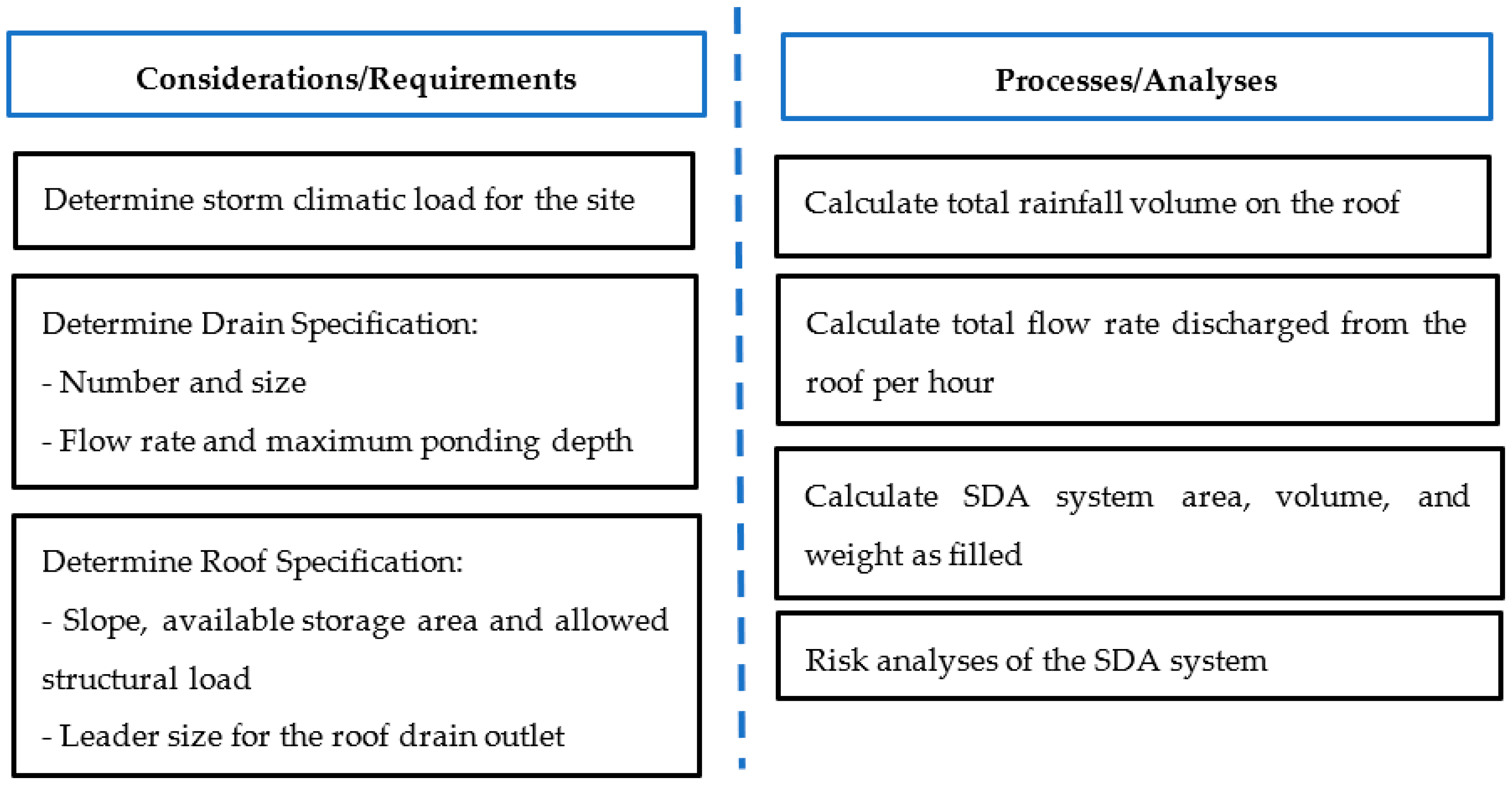
5. SDA Design Approach
Several variables such as wind, vortices, debris, roof design, roof obstructions, roof slope, micro-bursts, etc. can significantly affect the SDA system design. For instance, designers are advised to determine how the sloped surfaces leading to the drain will affect maximum ponding depth around the drain. However, in general, to design the SDA system, the first step is to determine the design climatic load which is the storm intensity, frequency, and duration. The second step is to determine the drain specifications (number and size; flow rate; and maximum ponding depth) and roof criteria (slope; available storage area; leader size for the roof drain outlet; and maximum live and dead loads allowed on the roof) specifications. The process includes but is not limited to rainfall volume on the roof calculation, total flow rate discharge from the roof per hour estimation, SDA system area, volume, and weight as filled, and risk analyses of the SDA system (
Figure 6).
Variables, such as slope of the roof surface, design of the structural roof components, and maximum load rating of the roof, can drive the maximum ponding value. The plumbing engineer is advised to consult local plumbing codes and work closely with the architect/structural engineer to agree upon a maximum ponding depth. The designer must determine real maximum achievable ponding depths that can exist, based upon roof surface slope to the drain, rainfall intensity, storm duration, micro-bursts, and flow capabilities of the roof drain. It is suggested to cross reference to select the leader size, pipe configuration, and maximum ponding depth to obtain a drain flow rate using the appropriate graph and pipe configuration. The number of roof drains is also required which is calculated by dividing the total flow rate by the drain flow rate. In addition, the designer should determine the roof area that each drain can cover by dividing the total roof area by the number of roof drains required. Finally, all the scenarios should be evaluated to ensure applicable codes and recommended sizing guidelines are followed and that results fall within allowable code requirements.
The SDA is fundamentally a modular tray system placed on top of the low-sloped roof acting as a detention tank. The module has an area
ASDA with a depth
hSDA and total effective drain area
AD. The total available storage for the system is the detention storage volume and/or any other components to increase the detention in the system. The detention time and detention volume both need to be maximized to effectively manage storm-water. Storm-water regulations, plumbing, and building codes typically mandate a drawdown time over which the detention facility will return to its initial design state (empty in this case). Drawdown time regulations vary across jurisdictions, but they are typically within 1–3 days of the start of storm event [
62,
63,
64,
65,
66,
67]. Accordingly, a preliminary design methodology has been developed based on peak storm-water intensity and duration, the drawdown time, and preventing of the MTD to be completely filled as follows:
- (1)
Determine the peak storm-water intensity (Si) for the appropriate design storm depth and storm-water hydrograph. Thus, the hyetograph curve is pictured based on SDA as a detention pond. The outflow from the orifice is estimated by:
where
CD is an appropriate discharge coefficient for the drain.
- (2)
Select a storage module depth (D) based on available products. The depth should be the largest available with less than the depth of the appropriate design storm. Determine the peak inflow (QS) by multiplying the peak intensity by the SDA area.
- (3)
Determine the effective orifice area (CDAO) such that the outflow rate through the orifice is equal to the peak inflow rate (QS):
The effective orifice area (CDAO) can be achieved with multiple outlets provided by the sum of the same effective area. The (CDAO) is a conservative value to ensure that no SDA will completely be filled during the design storm. For shallow modular tray, the storage capacity will be almost fully utilized, but for deeper modular tray, there may be additional capacity that is unused. If there is additional unused capacity, it may be possible to reduce the effective orifice area such that more storage capacity is utilized without completely filling the module. This in turn will increase the peak flow reduction of the SDA system.
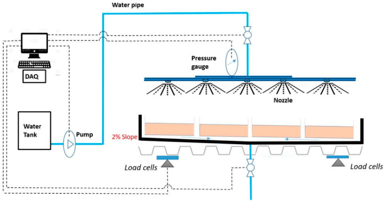
To elaborate on the proposed design criteria, in this study, first a storm simulator is designed and used to simulate the storm flow intensity and duration (
Figure 7). A computer-controlled pump provides water at a pre-programmed rate to simulate storm-water (storm-water design climatic load). The flow of storm-water is measured at the inflow meter, which records the inflow hydrograph. Measurements from the inflow meter are recorded with a Data Acquisition System (DAQ). Water flows through nozzles where it is converted into storm-water drops. The storm-water falls onto the SDA and the roof mock-up. The amount of water in the mock-up at any given time is measured and recorded by the DAQ. Water exits the mock-up through a drain at its center. The drain water flow rate is measured by the outflow meter, which is used to construct the outflow hydrograph.
Secondly, a roof with 2 m × 2 m area (6.5 ft × 6.5 ft) is designed and constructed to comply with the National Building Code of Canada (NBCC2015) requirements with slope less than 2%. Two different drain sizes with 3 inch and 3/4 inch are used in this mock-up to analyze the effects of drain size on storm capture and store on the roof.
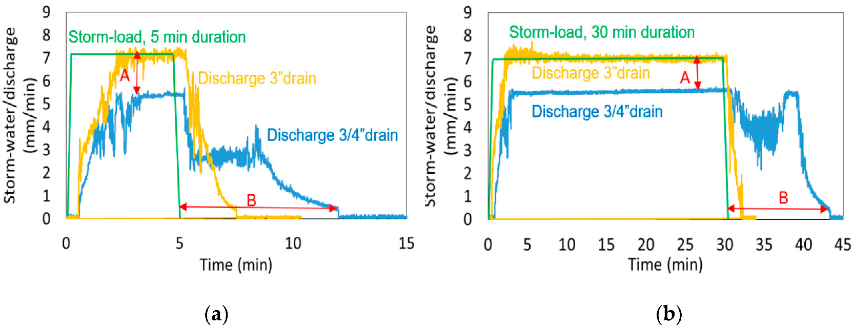
Figure 8 shows the storm-water discharge rate from the mock-up and the time in minutes that take to completely drain water from roof.
Figure 8a presents the storm-load in 5 min duration as
Figure 8b presents the same storm-load during 30 min. Larger drain diameter (3″ to ¾″) is associated with the drop in peak outflow rate, as A shows the water that is building up on the empty roof during the storm (detention capacity) and B presents an increase in total drainage time. These analyses indicate that water is stored on this roof mock-up during a severe storm for a longer time period when the drain size is smaller (3/4 inch) and thus storm-water takes longer to evacuate the roof.
6. SDA Challenges with Risk Lessening Techniques
The roofing components have been historically designed in a way to prevent sustained water ponding on the roof surface. Water that enters a roofing system, if not discharged in a timely manner, could lead to premature failure of roofs and also impact other building components and systems. Proper testing at the time of installation of the roofing system ensures the integrity of the assemblies. The parameters that need to be considered for such testing should determine the anticipated level of water ponding on the roof and the amount of time for which water may pool [
50,
51,
52]. In addition, leak detection sensors can be positioned within the roofing that will allow early detection of any moisture ingress into the assembly, before it becomes widespread. These are broadly covered under the category of leak detection systems.
In an SDA design, temperature fluctuations can also cause added degradation of the roofing system under detained water. Freeze-thaw events are the most damaging temperature fluctuation since a change of state is involved. It can increase the potential for damage to the material. Thermal expansion and contraction associated with freeze thaw cycles can impact seams in the roofing material, increasing the risk of water penetration. Ice damming resulting from freezing can further cause water detention greater than the designed load, becoming a structural hazard. In case of passive systems, proper sizing and location of drainage outlets need to be designed to avoid ice damming [
22,
67]. In case of active systems, valves can be controlled on the basis of anticipated weather conditions.
The MTD (Modular Tray Design) can also be collected and stored away during the winter months. Another method is using the Tile Tech on roofs that can actively melt frozen precipitation. The snow melting system, in a paver tile assembly, includes foam insulation under trays and a heat transfer and tubing system above the trays. If this technology is transferred to an SDA, it is possible to mitigate excessive snow load, while allowing the SDA to continue to serve its function in the winter months. Reducing risks of non-performance and failure of an SDA system will require careful consideration of the following [
50,
51,
52,
53,
54,
55]:
(I) Structural loading related to additional weight of detained water including consideration excessive deflection and collapse—this may require active or passive controls for amount of water stored on the roof and also appropriate structural evaluation and design of the roofing system.
(II) The performance of the main drain system and the overflow drain system—this may require ensuring redundancy in the design of the drain systems and also an inspection and maintenance plan to ensure anticipated functioning of the system.
(III) Material and system integrity of the roofing assembly with respect to ingress of moisture into the system and premature failure of the roofing system—this may be achieved by implementing quality control measures prior to the use of the roof for an SDA, implementing early warning system within the roof to detect moisture and a regular plan for inspection and maintenance of the roofing.
Therefore, there are three structural specifications to be determined before SDA installation and implementation [
61,
62,
63,
64,
65,
66,
67]:
(I) Storage volume on the roof by calculating available low-sloped roof area without the equipment or structures that may interfere with storm-water storage;
(II) Load imposed on the roofing assembly by calculating: (1) the traditional structural loads consisting of the dead weight of the roofing structure and materials, plus an allowance for live load caused by snow/rainfall events; and (2) the storm-water load, which is based on the climatic load and prediction of extreme storm fall intensity, duration, and frequency; and
(III) Waterproofing and insulation requirements specifying by the amount of the storm-water that is permitted to be detained to minimize unintentional adverse effects.
In addition, maintenance of the roofing assemblies is critical to the viability to the SDA function [
61,
62,
63,
64,
65,
66,
67]. Therefore, it is recommended to:
(I) Inspect and check the outlet and drain system in two cases following (1) storm event to ensure no blockage has occurred and (2) traffic or remedial works on or around the roof to ensure all drainage holes are clear and free for draining;
(II) Inspect and clear of any build up debris and leaf litters from each outlet by seasonal visit; and
(III) Inspect the waterproofing membrane at all junctions of penetrations to ensure it is firmly adhered.
Table 4 summarizes recommendations obtained from reviews on quality assurance metrics after and before SDA installation with proposed scheduled/frequency for each technique.
7. Concluding Remarks
Storm-water management is an issue in densely developed urban areas. Thus, it becomes increasingly important to investigate methods to manage storm-water in existing buildings. For such, priority is always placed on buildings’ structural integrity, but no guideline or best management practices exits to manage storm-water at building level. If a roof integrated system is considered, structural loading can be accounted for only by the strategic placement of the overflow drainage to limit the amount of water ponding on the roof. If a modular tray system is considered, the structural load can be accounted for by placing a limited number of trays or arranging them in an optimum configuration. However, the trays’ dead weight might take away potential detention capacity from the limited structural capacity. For both configurations, the next step is to investigate with further experiments and mock-ups of such assembly, to determine the right material and the amount of water that can be detained to develop a methodology to design such a system for an existing study, as there is still a limited amount of existing SDA being constructed and most importantly, monitored. Data from existing systems need to be collected to answer whether the above risks can be mitigated with certain methods.
In addition, while the SDA is gaining interest for managing storm-water and mitigating urban flooding, research is being conducted to investigate the possibility of optimizing such assembly with the integration of smart technologies in order to reduce the challenges and risks of the SDA system. The integration of smart sensors on SDA has the ability to drain roofs as needed and to prepare it for heavy precipitation events predicted by weather data. The smart SDA can use sensors, valves, controllers, and predictive weather algorithms to achieve an automated active system that monitors storm-water storage and automatically opens or closes roof drains by short-range weather forecasts. The SDA smart roof assembly can use smart flow control that responds to macro and micro information input to open and close automatically, from the weather forecast and groundwater level to meet storage capacity and household demands. These SDA systems that are supported by smart sensors and decision-making algorithms can facilitate the construction and be flexible from single rooftop to entire neighborhood. Smart systems are also the reason that rooftop practices are being brought to the light contemporarily. With further investigation into these strategies, rooftop assemblies can become an essential piece of the storm-water management system and hence a practical guideline is required. Here are the proposed topics for further investigation:
Material used in a modular tray system to be weather resistant.
Methods of securing the modular tray to the roof to address the wind uplift movement and structural loading.
Configuration of minimum modular tray layout to have a distinctive effect on storm-water runoff reduction.
Correlate the detention capacity of the SDA regarding the evapotranspiration from the system.
Determine the requirements of overflow drainage of the SDA that may be different from conventional roofs.
Membrane testing standards for the SDA to make sure there is no unintentional damages or leakage through the roofing system.
Life cycle assessment and performance of SDA evaluation.


