Article

Dynamic Characteristic and Parameter Analysis of a Modular Building with Suspended Floors

School of Civil Engineering, Lanzhou University of Technology, Lanzhou 730050, China
*
Author to whom correspondence should be addressed.
Buildings 2023, 13(1), 7; https://doi.org/10.3390/buildings13010007
Submission received: 7 November 2022 / Revised: 12 December 2022 / Accepted: 14 December 2022 / Published: 20 December 2022
(This article belongs to the Special Issue Advanced Design & Behavior of Concrete Structures)

Abstract

:
Over the past few years, modular buildings have become an important form of environmentally friendly architecture. Prefabricated construction methods have gained a lot of attention because they produce less construction waste and require less labor and water. However, the seismic performance of modular buildings needs to be improved. This paper proposes a prefabricated steel module with a suspended floor, which is based on a multi-tuned mass damped floor system. This paper also derives the form of a motion equation which is unified with the construction process of modular buildings, which can describe the change law of the mass, stiffness, and damping matrix of the structure in the processes of connecting the main structure with the suspended floor slab and of joining different floors. Since the performances of tuned mass damping devices are closely related to the dynamic characteristics of the structure, this paper uses ABAQUS for numerical analysis and mathematical induction (MI) to propose and verify a simplified method for calculating the lateral stiffness of the entire story from a single module’s lateral stiffness. Based on the principle of reducing the stiffness difference in the structure along different directions, a standard scheme of the horizontal extension of the module building is also specified. The results show that the simplified calculation method is reasonable and that the lateral stiffness of the structure increases linearly with the number of modules. Finally, the recommended values for the tuned frequency ratio and tuned damping ratio are given by investigating the dynamic response of the structure under Gaussian white noise excitation. The results show that the recommended tuning frequency ratio and damping ratio ranges in modular buildings are close to those for FIS buildings.

1. Introduction

In recent years, prefabricated buildings have attracted a lot of attention from engineers because of their advantages such as fewer on-site operations, shorter construction periods and high-quality prefabricated components. According to the degree of prefabrication, prefabricated buildings can be divided into three types: component level, structural level and building level. Modular buildings are a prefabricated building that are prefabricated at the building level [1]. As the prefabricated building with the highest degree of prefabrication, its structural response under earthquakes has become a hot topic for scholars to study. For example, Fathieh and Mercan used the IDA method to study multistorey modular buildings and showed that the rigid body displacement of module units under earthquake excitation was large, and the failure mode of module buildings in the floor plane was different from that of traditional buildings, which was generally represented by the failure of connecting nodes [2]. After that, many scholars have conducted much research in order to improve the performance of connection nodes. Some scholars have improved the bolted connection nodes [3,4,5], while others have proposed locking connection nodes [6,7,8]. These improvements and innovations reduce the difficulty of construction, but only consider the force transmission requirements of the nodes, and do not involve other seismic performances of modular buildings. Corfar and Tsavdaridis have reviewed and summarized numerous studies on nodes [9]. Farajian et al. have further summarized a classification system for interconnected rotary stiffness and strength characteristics in the context of swing angle support modules [10].
More factors have been taken into account in recent studies on the seismic performance of modular buildings, such as the design of modules, more properties of the connecting nodes and the integrity of the structure under extreme conditions. Peng et al. proposed a novel angular braced steel-concrete composite module design and discussed the influence of mortise joint and beam-to-beam bolt connections on the lateral stiffness of the module building [11]. Sendanayake et al. proposed a new type of connection between steel modules to achieve a safe, reliable and extended dynamic performance of a module building in an earthquake [12]. Shi et al. proposed an innovative inner sleeve composite bolt connection to improve construction capacity and seismic performance [13]. Qin et al. proposed a bolted connection with architectural beauty, and discussed the initial stiffness, ductility coefficient and energy dissipation capacity of the connection nodes in an earthquake [14]. Sharafi et al. proposed a modular integrated system (MIS) using projections and recesses to strengthen the connections between modules, and discussed its seismic performance and integrity under extreme conditions where the underlying support is not present [15]. The seismic performance of modular buildings is currently a topic of extensive investigation in various fields. However, there are not many reports of modular structures using vibration control technology to lessen their seismic reaction. Tuned mass dampers (TMD), as one of the most direct passive vibration control techniques, has been developing rapidly in the past 20 years. Recently, the TMD system used in traditional buildings has achieved the goal of equipping the main structure with no additional mass due to the introduction of a floor isolation system (FIS) [16,17]. Bin et al. reported the influence of dynamic coupling between the main structure and the isolated floor in a non-smooth non-linear FIS under seismic excitation [18]. Casagrande et al. compared the effect in FIS of viscous dampers and shape memory alloy dampers [19]. Xiang et al. reported the feasibility of using laminated viscoelastic materials to isolate floors to control the vibration of single- and double-layer steel frame structures [20,21]. This series of studies on FIS proves that eliminating the direct connection between the floor slab and frame in traditional buildings is effective in reducing the seismic response of buildings. The modular building with suspended floor slab proposed in this paper is an exploration of the application of FIS in prefabricated buildings.
It is very significant to determine the lateral stiffness and natural vibration frequency in modular buildings in structural analysis. This is because the FIS is very sensitive to the natural frequency of the main structure and the tuning frequency of the sub-structure. At the same time, the lateral stiffness of modular buildings is very different from that of traditional buildings. Farajian et al. studied diagonally supported modular steel structure buildings and proved that the connection mode between modules has no influence on the natural frequency of the structure [22]. However, the assembly mode and number of modules are obvious influencing factors for structural stiffness. On the other hand, the controlling effect of FIS technology is affected by the relative magnitude (frequency ratio) of the natural frequency of the main structure and the tuned frequency of the sub-structure. Therefore, in a modular building with a suspended sub-structure, the reasonable design of the frequency relationship between the main structure and the sub-structure is important to determine the damping effect.
To sum up, in the first part of this study, a novel hanging floor module building structure scheme is proposed, which realizes the introduction of vibration control technology into modular buildings. In the second part, combined with the construction process of the suspended floor module building, this paper studies the changes in the mass, stiffness and damping matrix of the building after considering the module assembly process. In the third part, using ABAQUS finite element analysis and mathematical induction, this paper proposes and verifies a more convenient method to calculate the lateral stiffness of modular buildings. In the fourth part, the dynamic equation proposed in the second part is used to calculate the displacement response of the building under Gaussian white noise excitation, and the dimensionless displacement response index is taken as the objective function to optimize the tuning frequency ratio and tuning damping ratio of FIS.

2. Configuration of Module Building with Suspended Floors

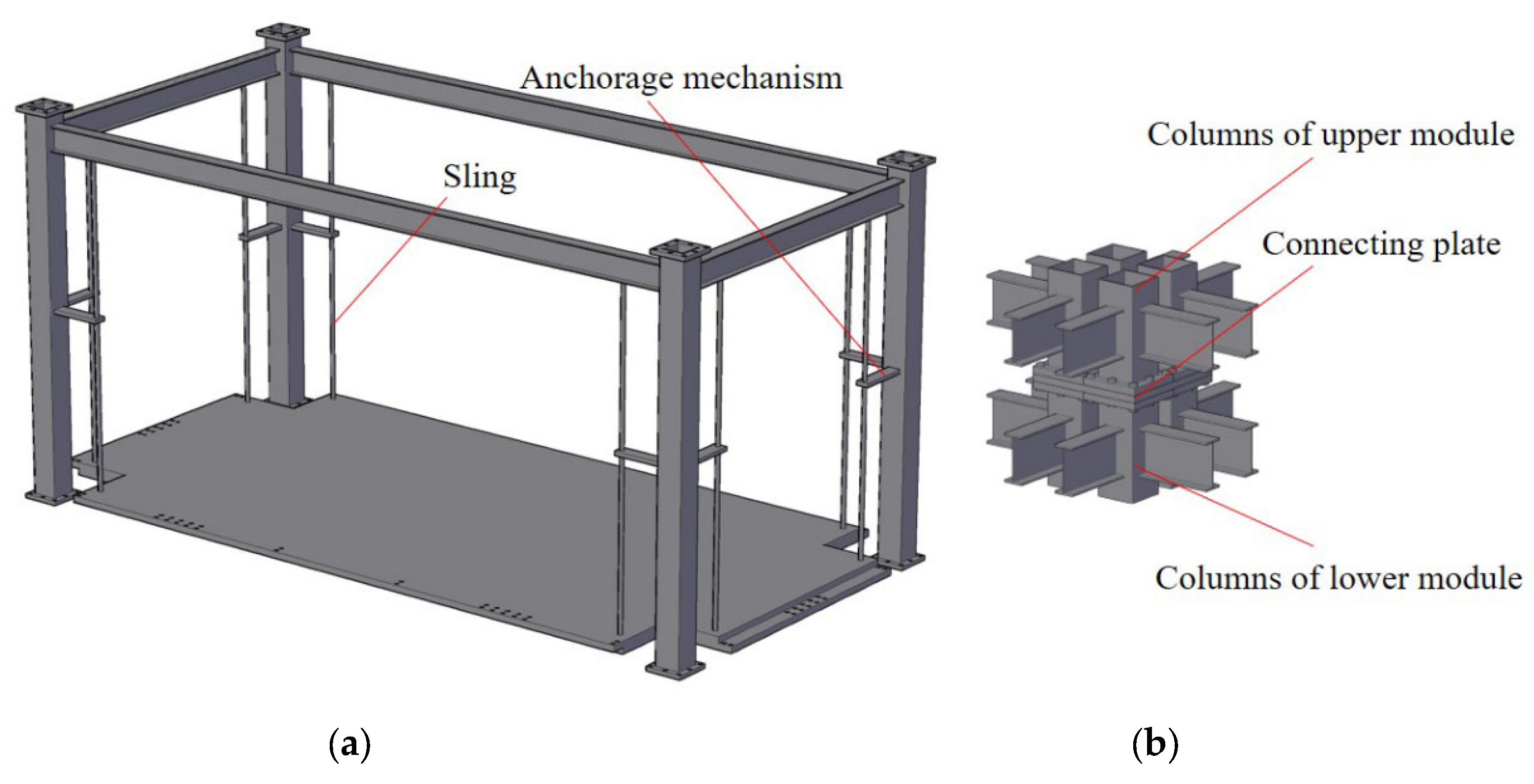
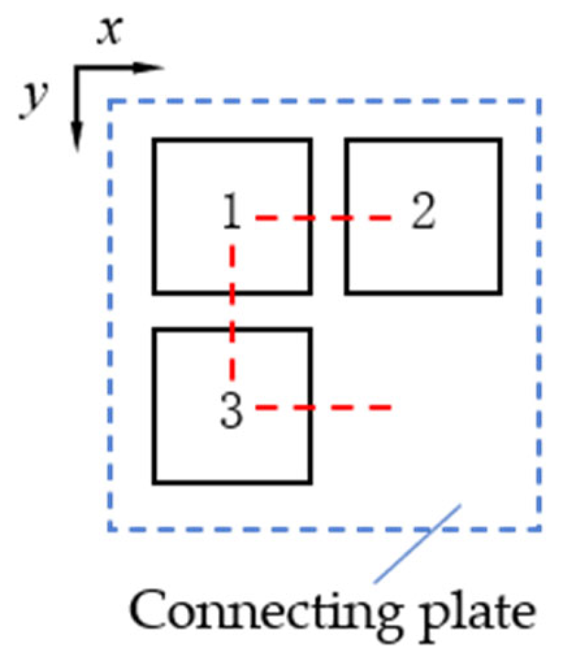
2.1. Configuration of Connection Nodes and Modules

The module configuration is shown in Figure 1a. The module ceiling beams use H-shaped steel, and the module columns use square steel tubes. Beams are welded to columns. A displacement space of 300 mm is reserved between the floor and the columns. Slings are placed at each corner of the floor and the floor is suspended from the ceiling beams. The sling features an anchorage mechanism that slides along the sling. When an earthquake is not occurring, the anchorage device moves to the lowest position, preventing the suspended floor from swinging. The floors of all modules on the same story are bolted together as a whole. The module degrades to an ordinary module at this point. The construction of connecting nodes is shown in Figure 1b. The connecting plates between the upper and lower module columns are fastened to ensure force transmission within the floor. When the modules are horizontally integrated with one another, the thickness of the connecting plates is 30 mm [23].

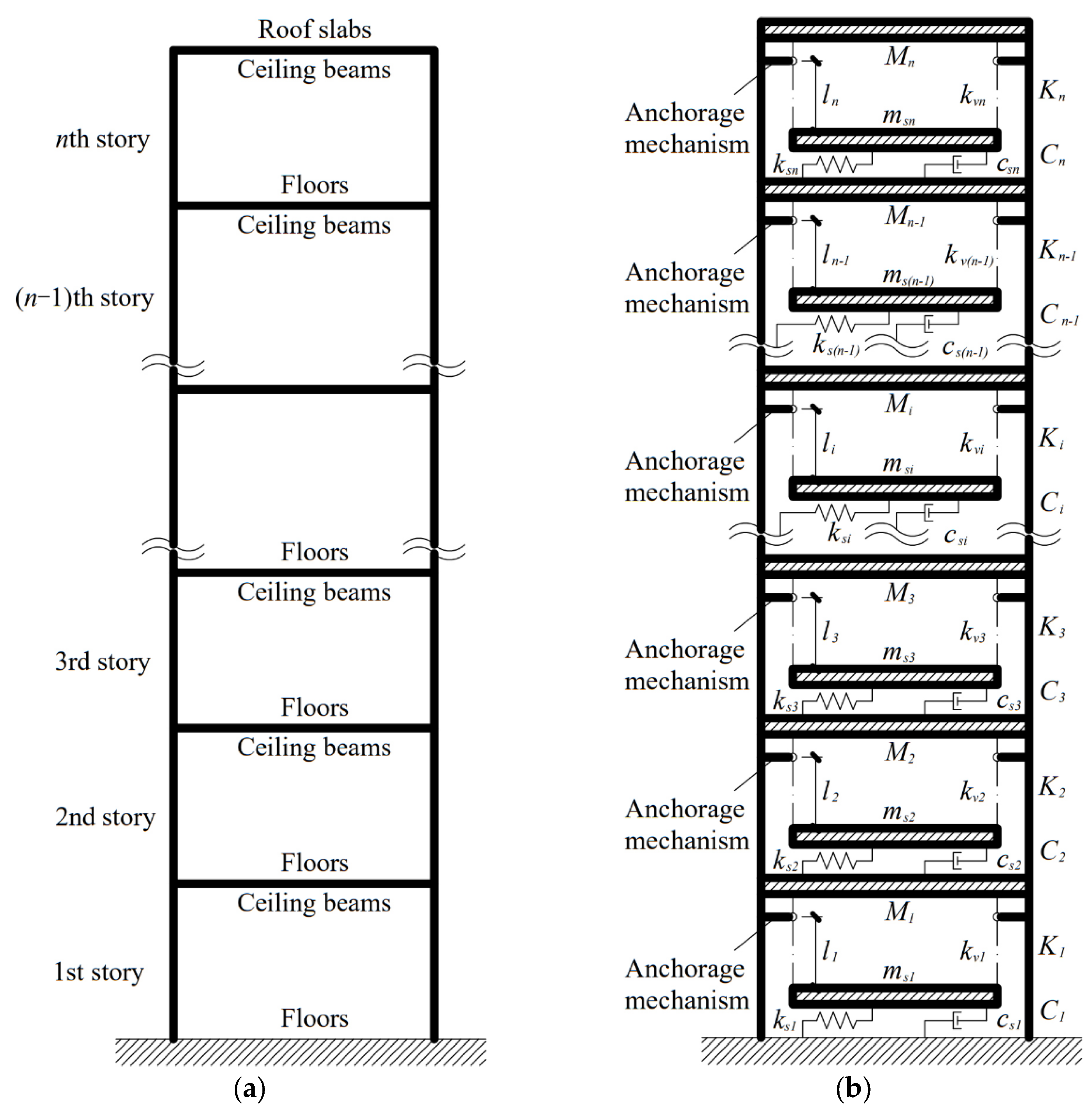
2.2. Structural Calculation Diagram

The modules are vertically connected and assembled as shown in Figure 2a, and the suspended floor module system is illustrated in Figure 2b.
The roof slabs of the modular building are not isolated from the ceiling beams of modules, using the traditional practice, and the springs and dampers on the ground floor are directly connected to the basics. In Figure 2b, Mi and msi are the concentrated masses of the main structure and substructure of the ith story, respectively. Ki, ksi, and kvi are the stiffness of the ith story’s main structure, the sum of the stiffness of the springs connecting the ith story’s suspended floors and main structure and the equivalent stiffness of the horizontal component of the force of the ith story’s sling, respectively. Ci and csi are the damping coefficient of the material of the ith story’s main structure and the sum of the damping coefficient of dampers connecting the ith story’s substructure and main structure, respectively. li is the length of the ith story’s sling.

3. Motion Equation

The motion equation of the n-story module building with suspended floors is as follows:
K v + C v ˙ + M v ¨ = p
where [K], [C] and [M] are the stiffness, damping and mass matrices, respectively. {p} is the load vector and {v} represents the displacement vector and can be written as:
v = v s 1 , v m 1 , v s 2 , v m 2 , , v s n , v m n T
where vsi and vmi represent the displacement response of the substructure and the main structure of the ith story, respectively.

3.1. Structure with the Swing-Suspended Floors

Both responses of the main structure and the suspended floors of the ith story are coupled with the motion of the main structure of the (i−1) story, where j is defined as j = i−1. The equilibrium equations of the jth story main structure, the ith story suspended floors, and the ith story main structure are given, respectively, as:
f S , i 1 + f D , i 1 + f I , i 1 = 0 f S , i , s + f D , i , s + f I , i , s = 0 f S , i + f D , i + f I , i = 0 ,
f S , i = k v i v i v s i + k s i + 1 ( v i v s i + 1 ) + K i v i v i 1 + K i + 1 v i v i + 1 ,
f D , i = c s i + 1 ( v ˙ i v ˙ s i + 1 ) + C i v ˙ i v ˙ i 1 + C i + 1 v ˙ i v ˙ i + 1 ,
f I , i = M i v ¨ i ,
f S , i , s = k v i v s i v i + k s i v s i v i 1 ,
f D , i , s = c s i v ˙ s i v ˙ i 1 ,
f I , i , s = m s i v ¨ s i ,
where fS,i, fD,I and fI,i are the spring force, damping force and inertia force of ith story’s main structure, respectively. fS,i,s, fD,i,s and fI,i,s are the spring force, damping force and inertia force of ith story’s suspended floor, respectively. kvi can be obtained from the simple pendulum model and be written as:
k v i = m s i g l i 2 2 v d i 2 l i 2 l i 2 v d i 2 + m s i v ˙ d i 2 + 2 v d i v ¨ d i l i 2 v d i 2 + 2 m s i v d i v ˙ d i 2 l i 2 v d i 2 2 ,
where vdi is the difference between the displacement of the ith story substructure and of the jth story main structure and can be written as (·)di=(·)si−(·)i−1. The ith story’s suspended floor is connected to the jth story’s main structure by springs and dampers, and connected to the ith story’s main structure by slings. Therefore, its stiffness matrix will have an additional coupling phenomenon compared with the ordinary FIS system. A defined matrix (3 × 3), [k]I, representing the stiffness matrix of the ith suspended floor is given by:
k i = + k s i k s i k s i + k s i + k v i k v i k v i + k v i .
The stiffness matrix of the ith story’s main structure, [K]I, can be obtained similarly:
K i = + K i 0 K i 0 0 0 K i 0 + K i .
[Kc]i is defined as the stiffness of a module with suspended floor, which represents the connecting process of the ith suspended floor and main structure and is written as:
K c i = k i + K i ,
or
K c i = + k s i + K i k s i K i k s i k s i + k v i k v i K i k v i + k v i + K i .
Since only vj is related to the jth story and ith story structure vibration at the same time, only the processing of the coefficients before vj is considered in matrix concatenation. vj in Equation (3) is extracted from the dynamic balance equation of the ith story main structure. Its coefficient is the sum of the elements of row 3 and column 3 of [Kc]j and the elements of row 1 and column 1 of [Kc]i. This paper uses the symbol “~” to define such matrix concatenation operations,
A ~ + B ~ = a 11 a 12 a 1 n a 21 a 22 a 2 n 0 n 1 × n 1 a n 1 a n 2 a n n + b 11 b 12 b 1 n b 21 b 22 b 2 n 0 n 1 × n 1 b n 1 b n 2 b n n .
[Ka]j,i is defined to represent the stiffness matrix of the assembled structure formed by connecting the jth and ith story:
K a j , i = K c j ~ + K c i ~ .
The complete form of [Ka]j,i can be written as:
K a j , i = + k s j + K j k s j K j 0 0 k s j + k s j + k v j k v j 0 0 K j k v j k v j + K j + k s i + K i k s i K i 0 0 k s i k s i + k v i k v i 0 0 K i k v i + k v i + K i .
[K] represents the stiffness matrix of the total structure formed by connecting all stories:
K = i = 1 n K c i ~ .
Similarly, [C]I and [c]i represent the damping matrix of the main and substructure of the ith story. [Cc]i represents the damping matrix of the structure formed by connecting the substructure and the main structure of ith story, and [C] represents the damping matrix of the total structure formed by connecting all stories. These matrices can be written as:
c i = + c s i c s i 0 c s i + c s i 0 0 0 0 ,
C i = + C i 0 C i 0 0 0 C i 0 C i ,
C c i = + c s i + C i c s i C i c s i c s i 0 C i 0 + C i ,
C = i = 1 n C c i ~ .
There is no coupling phenomenon in the acceleration of the upper and lower structures. [Mc]i represents the mass matrix of the ith story which combines the substructure and main structure, and [M] represents the mass matrix of the total structure. These matrices can be written as:
M c i = m s i M i ,
M = M c 1 M c 2 M c n .
[Kc]1 and [Cc]1, representing the stiffness and damping matrices of the underlying structure, are given by:
K c 1 = k s 1 + k v 1 k v 1 k v 1 + k v 1 + K 1 ,
C c 1 = c s 1 0 0 + C 1 .
The equilibrium equations of the 1st story’s main and substructure can be given according to Equation (3), and can be written as:
f S , 1 , s + f D , 1 , s + f I , 1 , s = 0 f S , 1 + f D , 1 + f I , 1 = 0 .

3.2. Structure with the Locked, Suspended Floors

When a suspended floor is locked and cannot swing, the mass of the substructure of the ith story will be concentrated on the jth story main structure. The stiffness, damping and mass matrices of the structure formed by connecting by the jth and ith story can be written as:
K a j , i = + k s j + K j k s j K j 0 k s j k s j + k v j k v j 0 K j k v j k v j + K j + K i K i 0 0 K i + K i ,
C a j , i = + c s j + C j c s j C j 0 c s j c s j 0 0 C j 0 C j + C i C i 0 0 C i + C i ,
M a j , i = m s j M j + m s i M i .
The stiffness, damping and mass matrices of the structure are exactly the same as those of the ordinary frame structure when all modules are locked.

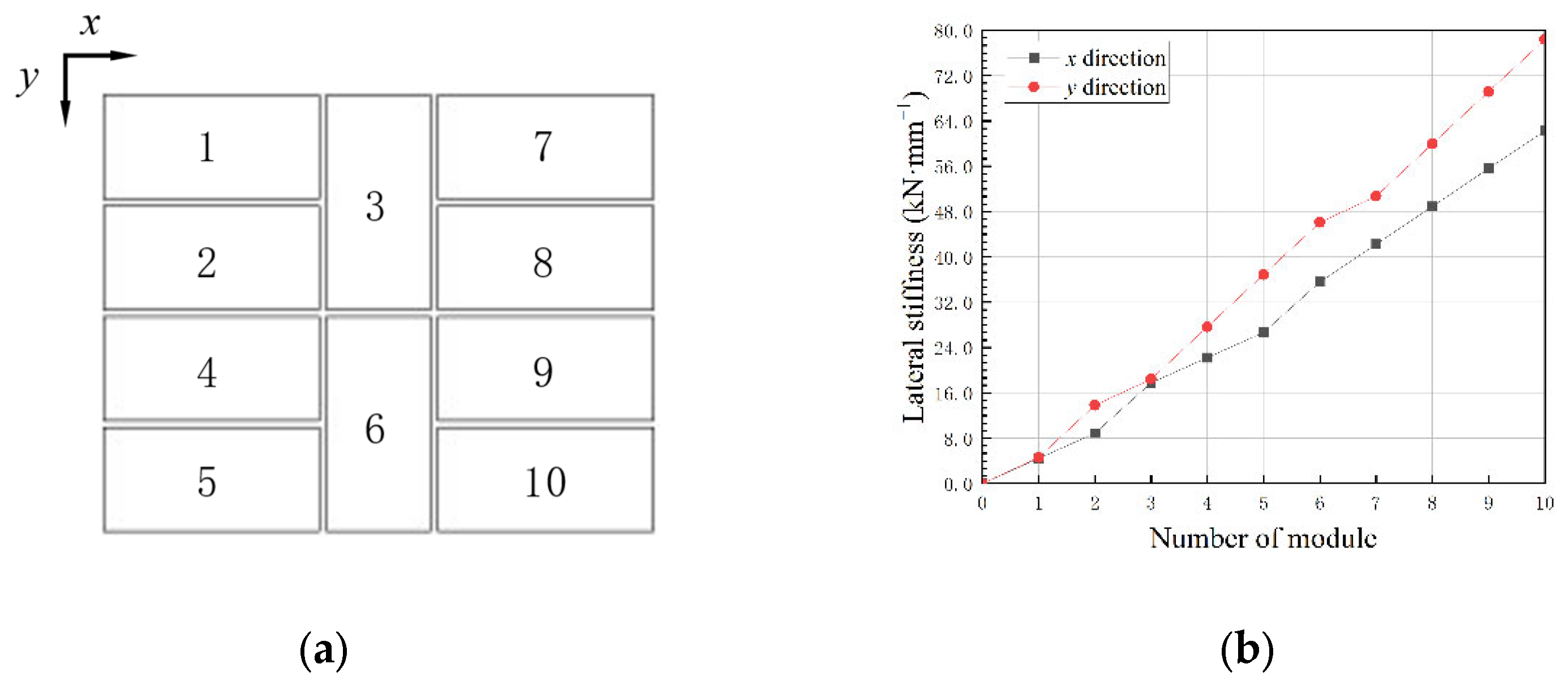
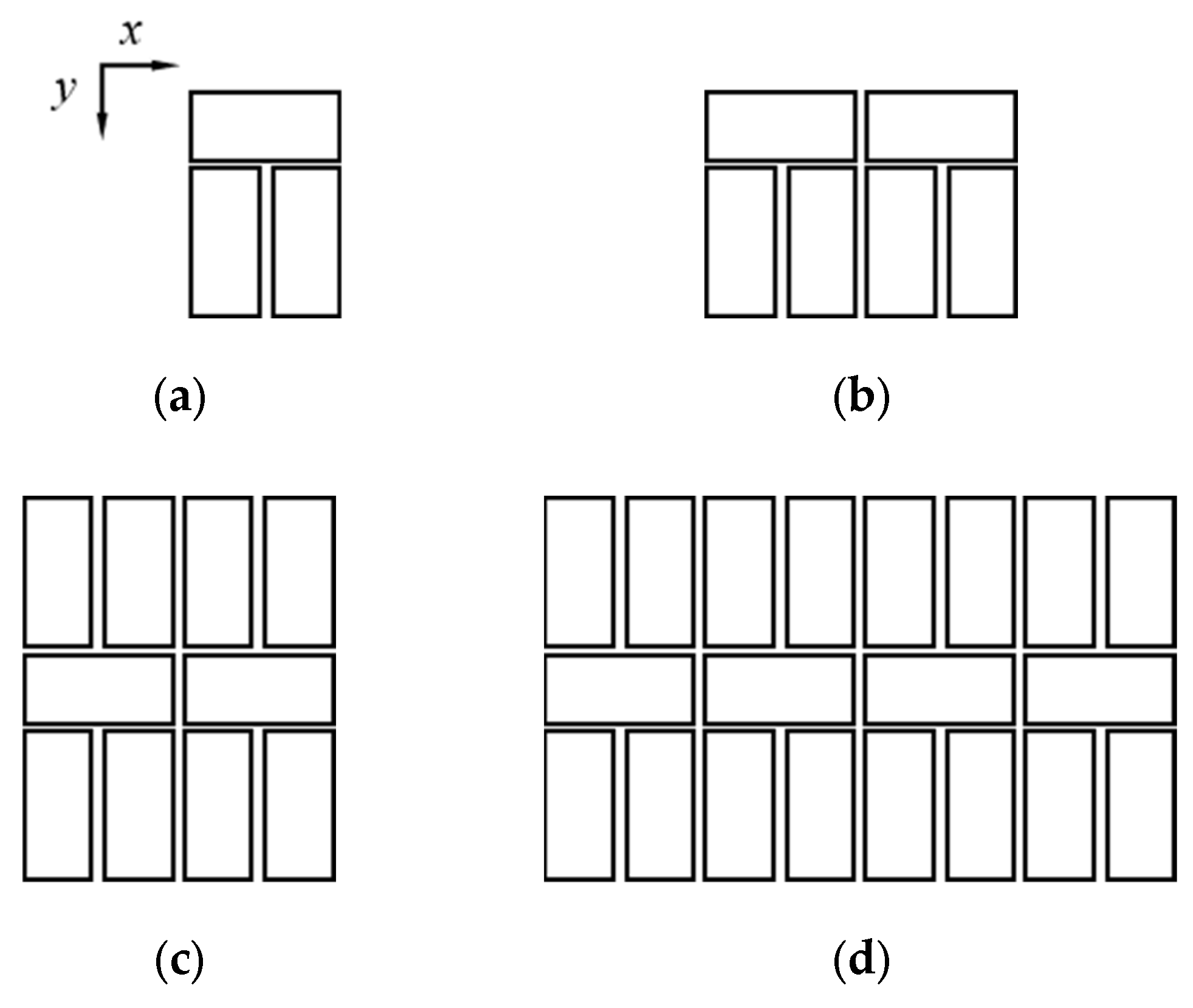
4. Effect of Increasing Modules

There are many horizontal assembly schemes for modular buildings, as shown in Figure 3. The lateral stiffness of the modular building extending with different schemes is discussed here. Each story is composed of q modules, and each module has four columns. K represents the lateral inter-story stiffness, which can be written as:
K = r = 1 4 q k r ,
where kr represents the lateral stiffness provided by one column in the module and the four columns in one module provide the same lateral stiffness. Finite element analysis can be used to determine Kx* and Ky*, which stand for the lateral stiffness of a single module along the x and y directions, respectively.
The lateral stiffnesses, kxr and kyr, provided by each module column along the x and y directions can be written as:
k x r = 1 4 K x * ,
k y r = 1 4 K y * .
After more modules are assembled horizontally, the module columns constrained by the connecting plates may provide greater lateral stiffness and this lateral stiffness is denoted as kr′. It is concluded that there is always a linear relationship between the lateral stiffness of the composed modular column, kr′, and the lateral stiffness of a single modular column, kr.
The size of a standardized module was taken as 2850 mm × 6000 mm × 3000 mm, to ensure that the columns are in alignment in various horizontal assembly schemes. The sections of module columns were taken as □200 × 8 [23]. Both section sizes of long beams and short beams of the module were taken as H200 × 100 × 5.5 × 8 [23]. The finite element modeling is shown in Figure 4b. Values of Kx* = 4447 N/mm and Ky* = 4612 N/mm were obtained according to the finite element analysis. Values of kxr = 1112 N/mm and kyr = 1153 N/mm were obtained according to Equations (26) and (27). The horizontal assembly scheme 3 is shown in Figure 3c, and its finite element modeling is shown in Figure 4c,d. It is concluded that Kx* = 8771 N/mm and Ky* = 13,699 N/mm.
The lateral stiffness of the structure shown in Figure 4c can be written as:
K x = 4 k x r + 4 k x r ,
K y = 4 k y r + 4 k y r .
Values of kxr′ = 1080 N/mm and kyr′ = 2271.75 N/mm were obtained according to Equations (28) and (29), that is, kxr′ = 1.0 kxr and kyr′ = 2.0 kyr.
The form of module assembly will affect the lateral stiffness of the modular building. The law is explained in detail by the three columns constrained by the connecting plate, as demonstrated in Figure 5.
When the connection between column 1 and column 2 is parallel to the x direction, the lateral stiffness of columns 1 and 2 are kx1′ = 2.0 kx1 and kx2′ = 2.0 kx2. Thus, columns 1 and 2 can be called the stiffness enhancement columns along the x direction.
Since column 3 has no other column in the x-direction to share the horizontal force with, the lateral stiffness of column 3 is kx3′ = 1.0 kx3. Therefore, the total lateral stiffness provided by columns 1, 2 and 3 in the x direction is kx1′ + kx2′ + kx3′ = 2.0 kx1 + 2.0 kx2 + 1.0 kx3. Similarly, the total lateral stiffness provided by the three columns in the y direction is ky1′ + ky2′ + ky3′ = 2.0 kx1 + 1.0 kx2 + 2.0 kx3. According to the rule and the certain assembly scheme, the lateral stiffness, K, of the story can be calculated through Equations (30) and (31), as long as the number of stiffness enhancement columns along a certain direction is calculated:
K = r = 1 p k r + r = p + 1 4 q k r ,
k i = 2 k i .
where p is the number of stiffness enhancement columns and q is the number of modules. When the modules are the same, kr is taken as k0, r = 1, 2, …, q. Then, Equations (30) and (31) can be simplified to:
K = p + 4 q k 0 .
In order to further verify the formula, under the condition that the number of modules is not more than three, the finite element analysis was carried out on the seven different assembly schemes shown in Figure 3 to obtain the lateral stiffness along the x and y directions. A comparison was made with the lateral stiffness calculated by Equation (32). The calculation results are shown in Table 1.
The data in Table 1 show that the average error between the lateral stiffness calculated by Equation (32) and by the finite element analysis is just 1.29%.
In addition, the lateral stiffnesses of the schemes in Figure 3e,f formed by three modules, are very close in the x and y directions. Thus, it is suggested that the horizontal assembly of the modular building should adopt similar ways to avoid obvious lateral stiffness differences in structures along different directions. Based on this, the standard scheme of the horizontal assembly of the modular building is proposed, and is shown in Figure 6a. The modular building is extended in the order from module 1 to module 10. To avoid irregularities in the building plan, it should not be the case that only modules 1 to 7 are assembled.
The lateral stiffness of the structure along the x and y directions in the standard scheme of horizontal assembly of the modular building with different module assembly numbers was investigated and is shown in Figure 6b.
Figure 6b shows that the lateral stiffness of the structure along the x and y directions is similar, and the stiffness along the y direction was slightly larger than that along the x direction during the entire assembly process.

5. Optimal Frequency and Damping Ratios

5.1. Structural Parameters and Objective Functions

The tuning ratio, v, which is the frequency ratio of the TMD to the main structure, and damping ratio, ζT, are two design parameters that can be used to frame the optimization problem [16]. The parameters of the dynamic characteristics of the modular building can be written as:
ω o p t = ν o p t ω 1 ,
k s i o p t = m s i ω o p t 2 ,
c s i o p t = 2 m s i ξ T o p t ω o p t ,
where ωopt is the optimal natural frequency of the substructure. ω1 is the frequency of the first mode of the main structure. msi is the mass of the ith story substructure. ksiopt and csiopt are the optimal spring stiffness and damper damping coefficient of the ith story substructure, respectively. The same spring and damper are utilized in each module since the modular building demands that the equipment requirements be as uniform as possible. Therefore, only a set of optimal νopt and ζTopt are required for each certain condition. Several researchers have reported νopt = 0.7 and ζTopt = 0.4 for a concrete structure [16]. Thus, νopt = 0.7 and ζTopt = 0.4 were used as the midpoints of their respective discussions in this paper.
In this paper, Python language was used to write a program to generate white Gaussian noise excitation, and Equation (1) was used for time–history analysis to calculate the displacement responses, vm and vs, of the main structure and the substructure, as well as their variances, σ m 2 and σ s 2 . However, the displacement response variance is related to the power, S0, of white noise excitation. This paper uses the dimensionless displacement variance indexes, Rm and Rs, as the objective functions of structural optimization [24].
Under the excitation of Gaussian white noise, the displacement variance of the structure can be written as:
σ m 2 = S 0 + G m i ω G m i ω d ω ,
σ s 2 = S 0 + G s i ω G s i ω d ω .
where Gm and Gs are the displacement response transfer functions of the main structure and the secondary structure, respectively. Dimensionless variables λ = ω/ωm and υ = ωs/ωm are introduced so that Equations (36) and (37) can be further written as:
σ m 2 = S 0 i ω m 3 + F m i λ d ω ,
σ s 2 = S 0 i ω m 3 + F s i λ d ω .
Since the time–history analysis was used in this paper to calculate the variance of structural displacement response, Equations (38) and (39) were only used as the basis for eliminating the influence of S0, so the functions Fm and Fs are not derived in detail. The specific derivation process can be found in the literature [24].
Based on Equations (38) and (39) and the literature [24], the dimensionless displacement variance indexes, Rm and Rs, which are independent of S0, are obtained:
R m = ω m 3 2 π S 0 σ m 2 ,
R s = ω m 3 2 π S 0 σ s 2 .
where σ m 2 and σ s 2 are the square of displacement response of secondary and main structure, respectively. ωm is the natural frequency of the main structure. Rm and Rs are the non-dimensional displacement variances of the standardized main structure and substructure according to the different white noise excitation intensities and the natural frequency of the main structure.

5.2. Optimal Parameters

The mass of the ith story main structure of a single module is taken as Mi* = 9168.35 kg, i = 1, 2,…, n−1, and Mn* = 18,005.50 kg. The mass of the ith story substructure of a single module is taken as msi* = 8837.15 kg, i = 1, 2,…, n. The lateral stiffness of the ith story’s main structure of a single module is taken as Ki* = 4447 kN/m. The damping ratio of the steel structure is taken as ξ = 0.02. The damping coefficient of the ith story main structure Ci can be written as:
C i = 2 ξ K i M i .
Horizontal and vertical assembly of the modular building were considered. There are four schemes of horizontal assembly of the modular building as shown in Figure 7.
In this paper, the stepwise search method was adopted to optimize the tuning frequency ratio and damping ratio with the step size of 0.1. The constraints are as described above, where v ∈ [0.0, 1.4] and ζT ∈ [0.0, 0.8]. The objective functions are Equations (40) and (41).
When the modular building with suspended floors has only one story, with four horizontal assembly schemes, the responses of the substructures Rs1 and that of the main structure R1 are given in Figure 8.
Figure 8 shows that the responses of the main and substructure were the smallest when the tuning ratio was taken as ν = 0.1. When the damping ratio of the damper was taken as ζT = 0, the response of the substructures is obviously larger than those of the substructures equipped with dampers. When the damping ratio was taken as ζT > 0.1, the boundary benefit of the response of the substructures decreased gradually. When the damping ratio was taken as ζT = 0.5, the response of the substructures was smallest. When the modular building had only one story, the response of the main structure did not change with the tuning ratio and damping ratio. The dynamic response of a single-story building was not significantly different when modular buildings had different plane layouts and assembly schemes. A tuning ratio of ν = 0.1 and a damping ratio of ζT = 0.5 are recommended. When the number of modules was twenty with a damping ratio of ζT = 0.5, the sum of the damping coefficients of all the dampers was 0.7 × 10⁶ N·s/m. The damping coefficients of dampers commonly used in TMD are 0.5~4.0 × 10⁶ N·s/m, which can meet the requirements.
In summary, when the structure has only one story, the displacement response of the main structure under the excitation of white Gaussian noise does not change with the increase in tuning frequency ratio, while the displacement response of the substructures structure shows a changing rule of first decreasing and then increasing. The substructures displacement response was the smallest when the corresponding tuning frequency ratio was ν = 0.1. With an increase in the damping ratio, the displacement response of the main structure does not change, while the displacement response of the substructures structure decreases first. When the damping ratio was ζT > 0.5, there was no significant change.
Therefore, it is recommended to use a tuning–frequency ratio of ν = 0.1 and a damping ratio of ζT = 0.5 for building a suspended floor module.
For the case where the modular building with suspended floors was vertically extended to three stories and five stories, the responses of the substructure Rsi and that of the main structure Ri were investigated and are shown in Figure 9 and Figure 10, respectively.
Similar to the one-story modular building with suspended floors, Figure 9 and Figure 10 demonstrate that the substructures’ responses were minimal when the tuning ratio was v = 0.1 to 0.2. The reactions of the substructures were greater when the damping ratio was ζT = 0. The boundary advantage of the substructure response steadily declined when the damping ratio was ζT > 0.1. When the damping ratio was ζT = 0.5, the substructures’ responses were at their smallest. The main structural responses were likewise substantial, with a damping ratio of ζT = 0. When the tuning ratio was v > 0.7, the responses of the main structure were not noticeably affected with increasing v. The response of the main structures was the least when ν = 0.8~1.0 and ζT = 0.5, respectively.
In conclusion, when the structure is three or five stories, and the tuning–frequency ratio is between ν = 0.1 and 0.2, it is advantageous to suppress the displacement responses of the substructures, while when the tuning–frequency ratio is between ν = 0.8 and 1.0, it is advantageous to suppress the displacement response of the main structure. The effect of the damping ratio on the main structure and the secondary structure is very similar, and also very similar to that of the one-story structure, so a ζT of 0.5 is still recommended.
A comparison between the recommended values of this study and the optimal values reported in the literature [16] is shown in Table 2.
As can be seen from the table, the recommended values in this study are consistent with the optimal values reported in the existing literature, which verifies the rationality of the results. At the same time, this study is supplemented in reducing the substructure response.

6. Conclusions and Discussions

The form of a mass, damping and stiffness matrix that can reflect the assembly of modules with suspended floors is provided in this work. Based on finite element analysis and theoretical induction, the lateral stiffness of modular buildings using the different schemes of horizontal assembly are investigated and verified. The subsequent investigation examined those optimal values of the tuning ratio, ν, and damping ratio, ζT.
Several conclusions can be drawn from this study:
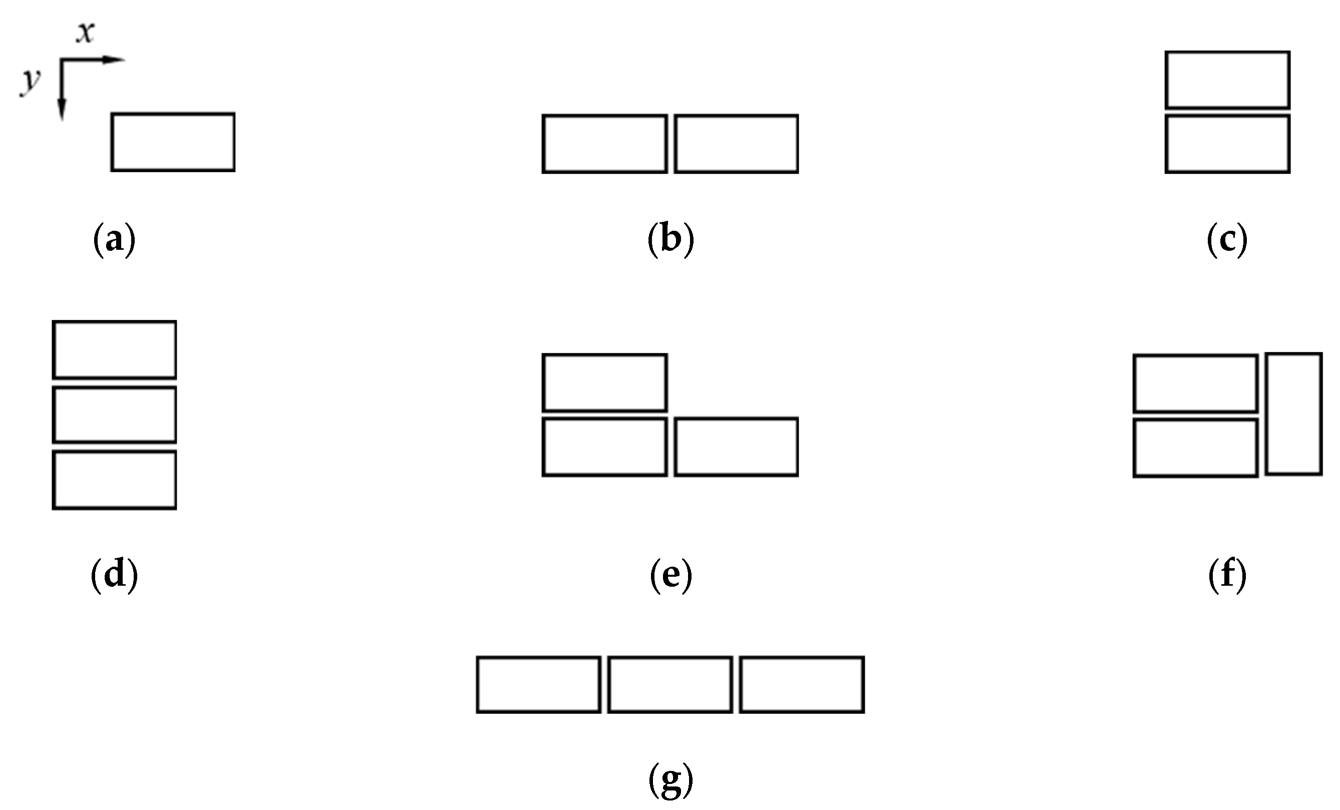
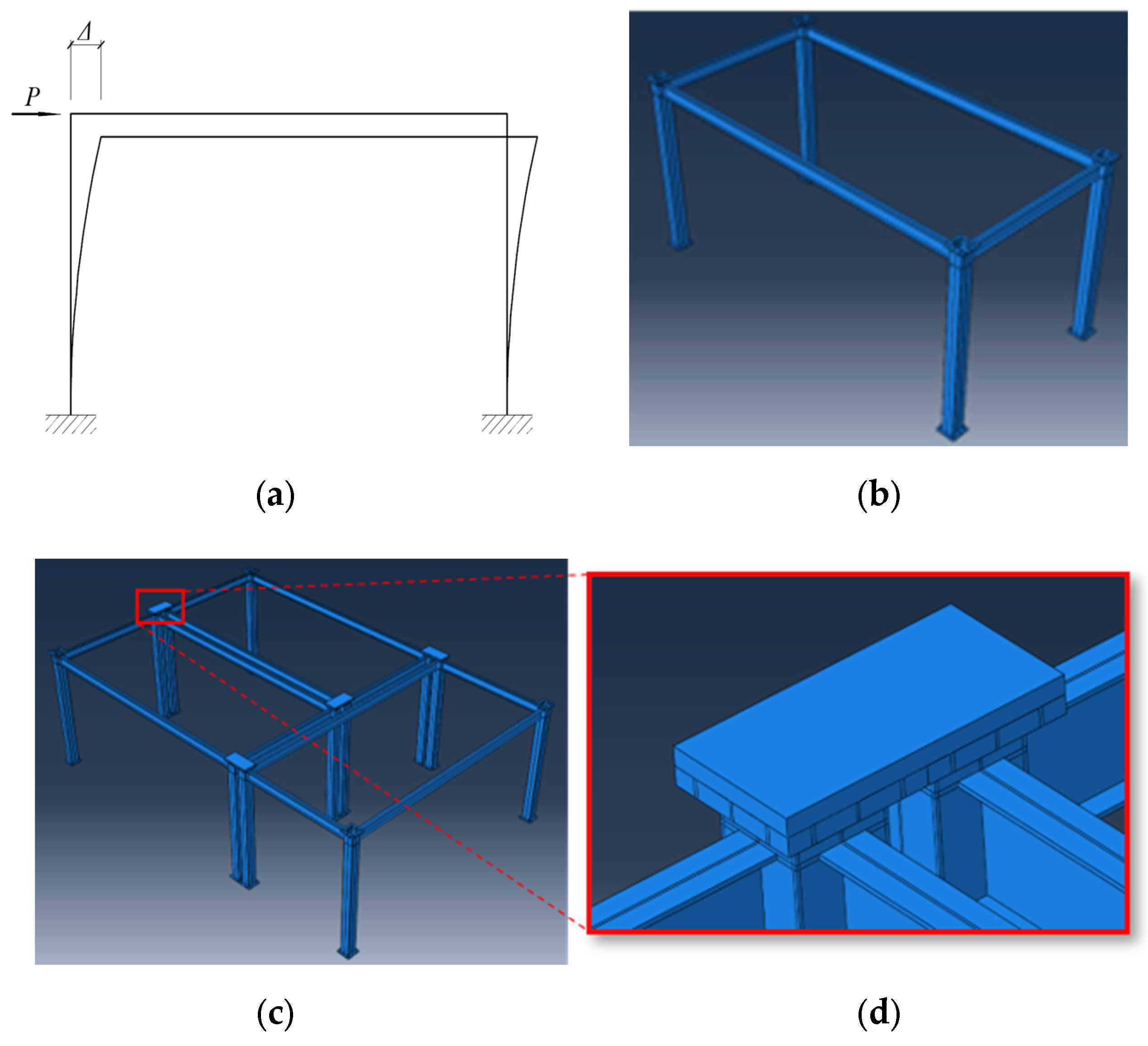
  • The simplified lateral stiffness calculation method has good calculation accuracy, and the lateral stiffness of modular buildings increases linearly with the increase in the number of modules;
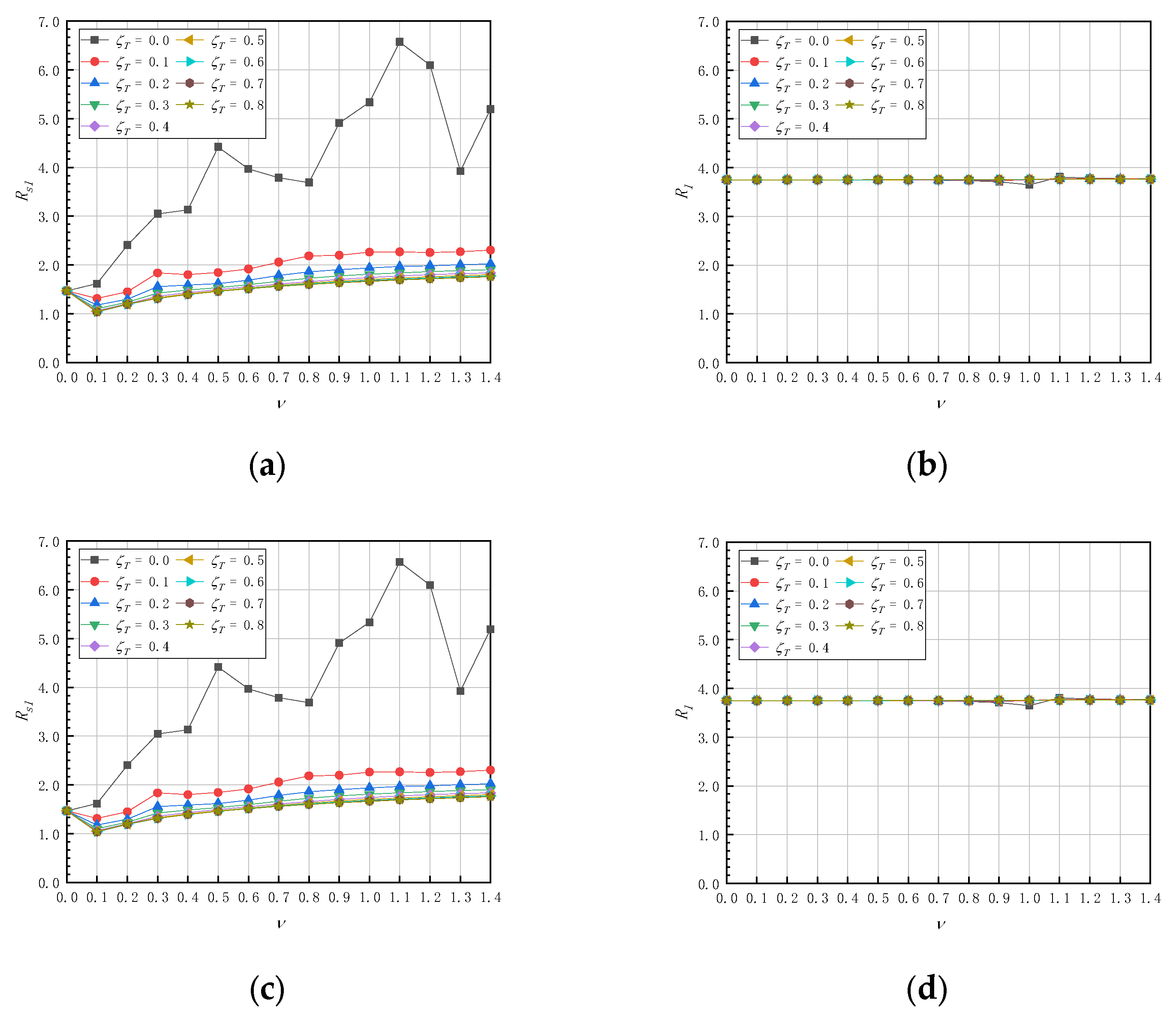
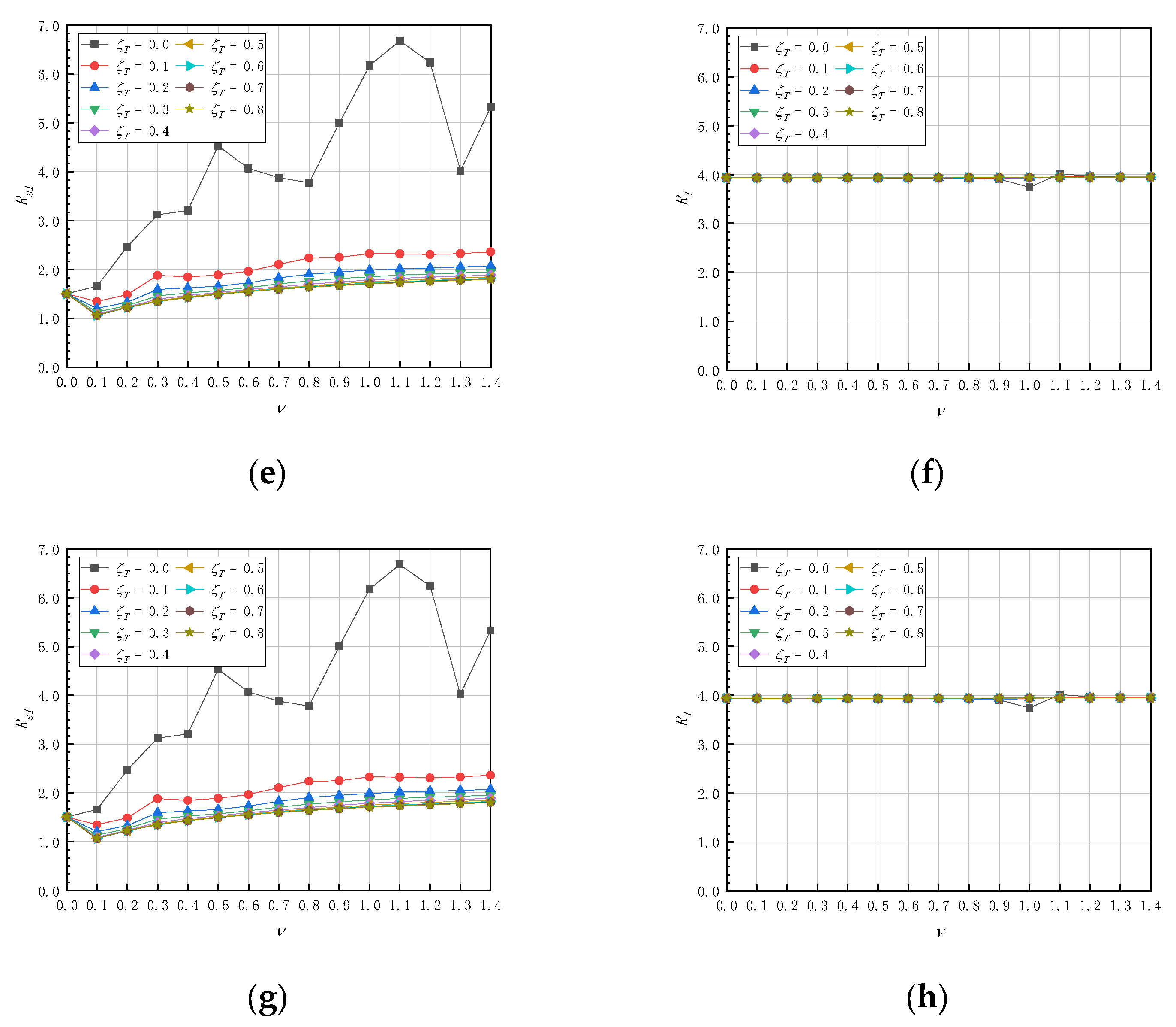
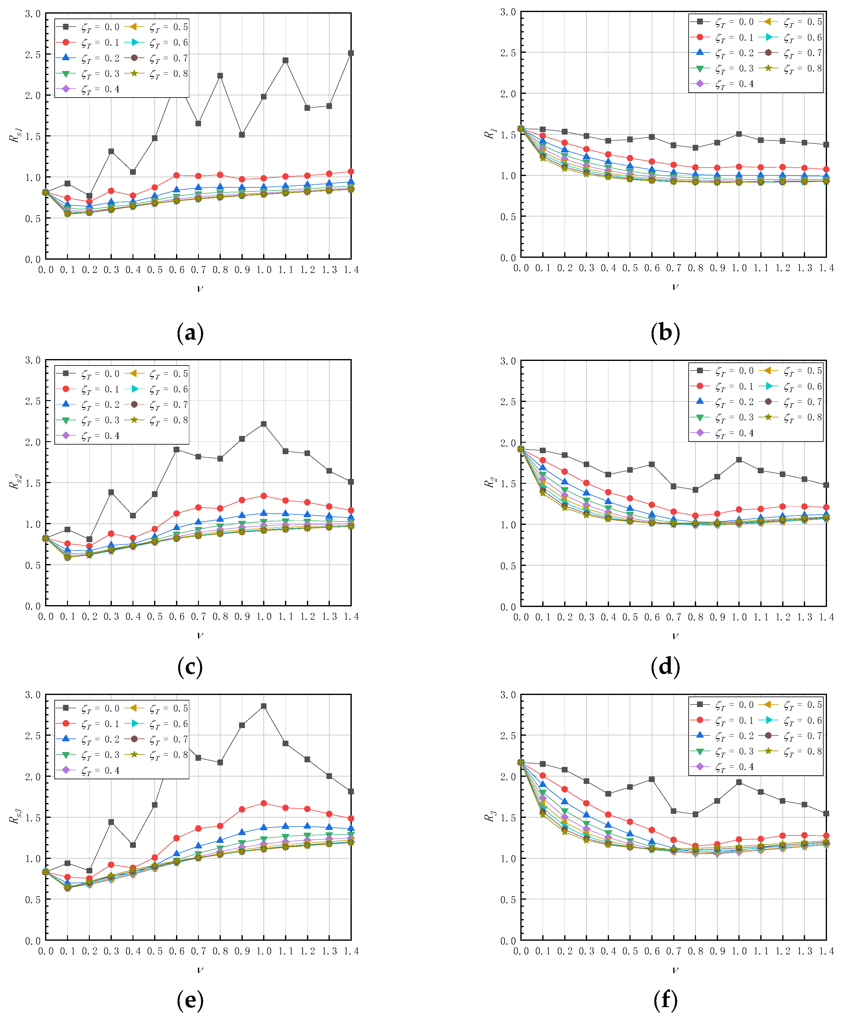
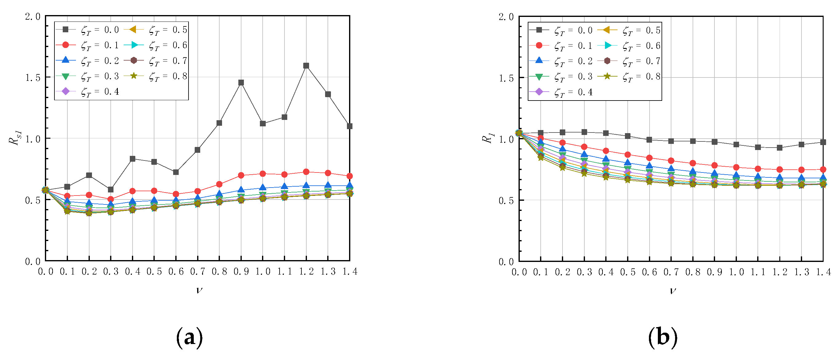
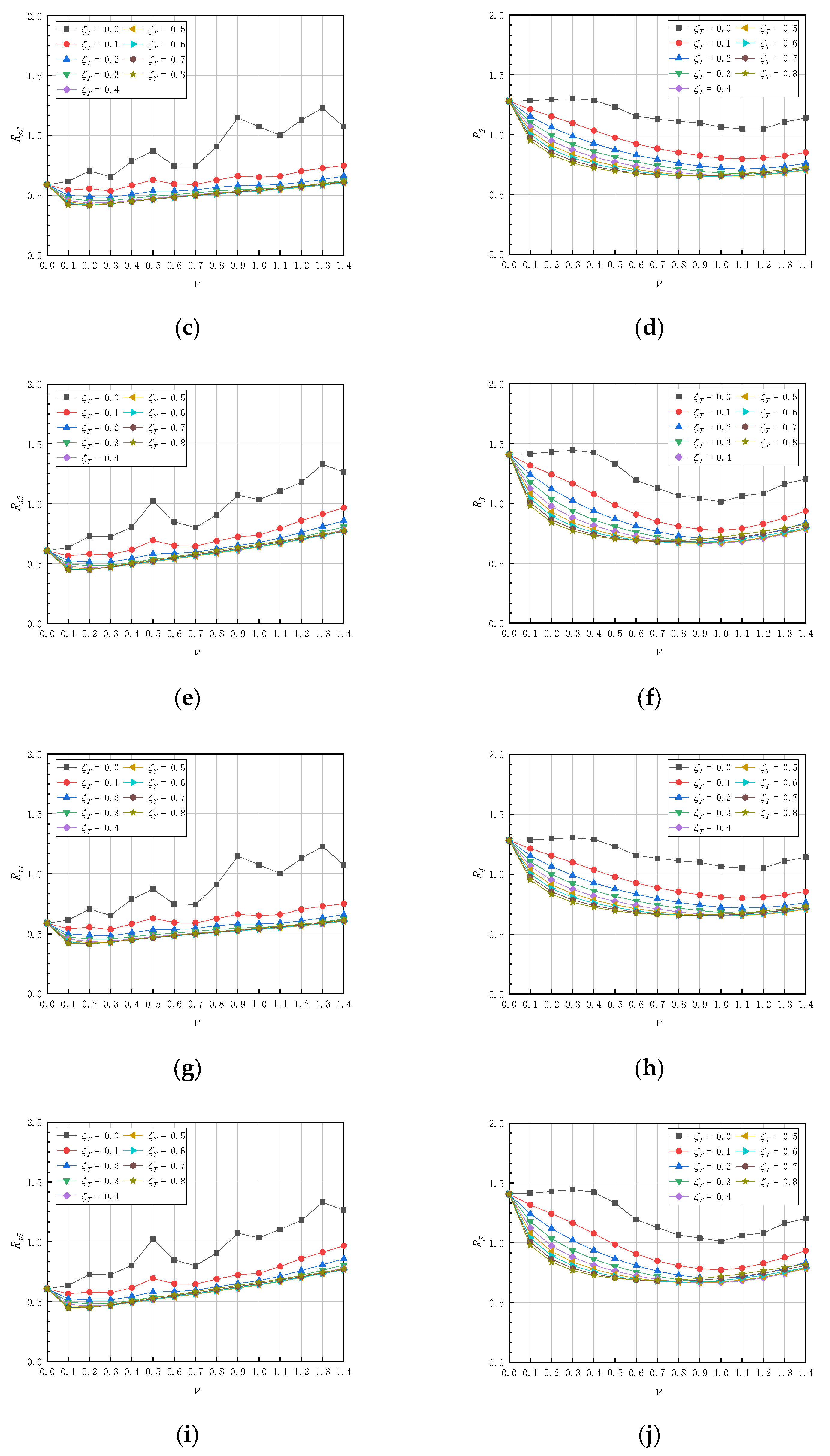
  • Modular buildings with suspended floors are recommended to have different tuning frequency ratios depending on the vibration control objects;
  • To control the vibration of the substructure, the tuning ratio is recommended to be ν = 0.1~0.2. To minimize the response of the main structure, a ν = 0.8~1.0 is recommended;
  • It is not necessary for the dampers’ initial stiffness to be very high for a modular structure with suspended floors. As a result, it is advised to utilize magnetorheological or viscous dampers of the velocity-dependent type, with a damping ratio of ζT = 0.5;
  • However, there are some limitations to this study: (a) Although FIS vibration technology is used in this study, it is not modularized with the building, and only considers the case that the tuning frequency of each floor is the same. (b) The emphasis of this paper is only on the analysis of the structure. To make this system practical, a scheme concerning acoustic insulation, thermal insulation and other properties related to the building function needs to be researched. (c) This paper puts forward the concept of a modular building introduced by FIS, which is poorly considered in terms of economic benefits and practicability. (d) This paper only discusses the response of the structure under the excitation of white noise and needs to include cases experiencing small, medium and large earthquakes.

Author Contributions

Conceptualization, S.Z. and Q.H.; methodology, Q.H.; software, S.Z.; validation, Q.H., J.S. and S.Z.; formal analysis, S.Z.; investigation, S.Z.; data curation, S.Z.; writing—original draft preparation, S.Z.; writing—review and editing, Q.H.; visualization, J.S.; supervision, Q.H.; project administration, Q.H. All authors have read and agreed to the published version of the manuscript.

Funding

Gansu Construction Tech. Project 2021-21.

Conflicts of Interest

The authors declare no conflict of interest.

References

  1. Li, A.Q.; Zhou, T.; Liao, Z.W. State of the art of modular building system. Ind. Constr. 2018, 48, 132–139+150. (In Chinese) [Google Scholar]
  2. Fathieh, A.; Mercan, O. Seismic evaluation of modular steel buildings. Eng. Struct. 2016, 122, 83–92. [Google Scholar] [CrossRef]
  3. Cho, B.H.; Lee, J.S.; Kim, H.; Kim, D.J. Structural performance of a new blind-bolted frame modular beam-column connection under lateral loading. Appl. Sci. 2019, 9, 1929. [Google Scholar] [CrossRef] [Green Version]
  4. Qiu, C.; Bai, Y.; Zhang, L.; Jin, L. Bending performance of splice connections for assembly of tubular section FRP members: Experimental and numerical study. J. Compos. Constr. 2019, 23, 04019040. [Google Scholar] [CrossRef]
  5. Sendanayake, S.V.; Thambiratnam, D.P.; Perera, N.; Chan, T.; Aghdamy, S. Seismic mitigation of steel modular building structures through innovative inter-modular connections. Heliyon 2019, 5, e02751. [Google Scholar] [CrossRef]
  6. Dai, X.M.; Zong, L.; Ding, Y.; Li, Z.X. Experimental study on seismic behavior of a novel plug-in self-lock joint for modular steel construction. Eng. Struct. 2019, 181, 143–164. [Google Scholar] [CrossRef]
  7. Chen, Z.; Liu, Y.; Zhong, X.; Liu, J. Rotational stiffness of inter-module connection in mid-rise modular steel buildings. Eng. Struct. 2019, 196, 109273. [Google Scholar] [CrossRef]
  8. Chen, Z.; Wang, J.; Liu, J.; Khan, K. Seismic behavior and moment transfer capacity of an innovative self-locking inter-module connection for modular steel building. Eng. Struct. 2021, 245, 112978. [Google Scholar] [CrossRef]
  9. Corfar, D.A.; Tsavdaridis, K.D. A comprehensive review and classification of inter-module connections for hot-rolled steel modular building systems. J. Build. Eng. 2022, 50, 104006. [Google Scholar] [CrossRef]
  10. Farajian, M.; Sharafi, P.; Eslamnia, H.; Kildashti, K.; Bai, Y. Classification of inter-modular connections for stiffness and strength in sway corner-supported steel modular frames. J. Constr. Steel Res. 2022, 197, 107458. [Google Scholar] [CrossRef]
  11. Peng, J.; Hou, C.; Shen, L. Numerical analysis of corner-supported composite modular buildings under wind actions. J. Constr. Steel Res. 2021, 187, 106942. [Google Scholar] [CrossRef]
  12. Sendanayake, S.V.; Thambiratnam, D.P.; Perera, N.J.; Chan, T.H.T.; Aghdamy, S. Enhancing the lateral performance of modular buildings through innovative inter-modular connections. In Structures; Elsevier: Amsterdam, The Netherlands, 2021; Volume 29, pp. 167–184. [Google Scholar]
  13. Shi, F.W.; Li, Y.M. Innovative inner sleeve composite bolted connections for modular steel constructions: Experimental and numerical studies. J. Build. Eng. 2022, 64, 105624. [Google Scholar] [CrossRef]
  14. Qin, J.; Tan, P. Design method of innovative box connections for modular steel constructions. J. Build. Eng. 2022, 57, 104820. [Google Scholar] [CrossRef]
  15. Sharafi, P.; Mortazavi, M.; Samali, B.; Ronagh, H. Interlocking system for enhancing the integrity of multi-storey modular buildings. Autom. Constr. 2018, 85, 263–272. [Google Scholar] [CrossRef]
  16. Xiang, P.; Nishitani, A. Seismic vibration control of building structures with multiple tuned mass damper floors integrated. Earthq. Eng. Struct. Dyn. 2014, 43, 909–925. [Google Scholar] [CrossRef]
  17. Xiang, P.; Nishitani, A. Optimum design of tuned mass damper floor system integrated into bending-shear type building based on H∞, H2, and stability maximization criteria. Struct. Control Health Monit. 2015, 22, 919–938. [Google Scholar] [CrossRef]
  18. Bin, P.; Tehrani, M.H.; Nisa, M.; Harvey, P.S., Jr.; Taflanidis, A.A. Analysis and optimization of a nonlinear dual-mode floor isolation system subjected to earthquake excitations. Earthq. Eng. Struct. Dyn. 2021, 50, 2334–2354. [Google Scholar] [CrossRef]
  19. Casagrande, L.; Villa, E.; Nespoli, A.; Occhiuzzi, A.; Bonati, A.; Auricchio, F. Innovative dampers as floor isolation systems for seismically-retrofit multi-storey critical facilities. Eng. Struct. 2019, 201, 109772. [Google Scholar] [CrossRef]
  20. Xiang, Y.; Koetaka, Y.; Okuda, N. Single-story steel structure with LVEM-isolated floor: Elastic seismic performance and design response spectrum. Eng. Struct. 2019, 196, 109314. [Google Scholar] [CrossRef]
  21. Xiang, Y.; Koetaka, Y. Structural feasibility of incorporating the LVEM-isolated floor in the first story of a two-story steel frame. Eng. Struct. 2019, 199, 109686. [Google Scholar] [CrossRef]
  22. Farajian, M.; Sharafi, P.; Alembagheri, M.; Kildashti, K.; Bigdeli, A. Effects of bolted connections’ properties on natural dynamic characteristics of corner-supported modular steel buildings. In Structures; Elsevier: Amsterdam, The Netherlands, 2022; Volume 45, pp. 1491–1515. [Google Scholar]
  23. Yang, C.; Xu, Y.C.; Ou, J.P. Fabricated steel modular column-column and beam-beam combination frame structure and its seismic performance analysis. Earthq. Eng. Eng. Dyn. 2022, 42, 34–45. (In Chinese) [Google Scholar]
  24. Cao, L.; Li, C. Tuned tandem mass dampers-inerters with broadband high effectiveness for structures under white noise base excitations. Struct. Control Health Monit. 2019, 36, e2319. [Google Scholar] [CrossRef]
Figure 1. Constructions of (a) modules and (b) connecting notes.
Buildings 13 00007 g001
Figure 2. (a) Modules after vertical assembly and (b) Suspended floor modular system.
Buildings 13 00007 g002
Figure 3. Schemes of horizontal assembly: (ag) scheme 1 to 7.
Buildings 13 00007 g003
Figure 4. Finite element analysis: (a) calculation diagram and model of (b) scheme 1, (c) scheme 3 and (d) connecting plate.
Buildings 13 00007 g004
Figure 5. Three columns constrained by a connecting plate.
Buildings 13 00007 g005
Figure 6. (a) A standard scheme of horizontal assembly and (b) Lateral stiffness of the structure.
Buildings 13 00007 g006
Figure 7. Schemes of horizontal assembly formed by (a) 3, (b) 6, (c) 10 and (d) 20 modules.
Buildings 13 00007 g007
Figure 8. Responses of (a,c,e,g) the substructures and (b,d,f,h) the main structures formed by 3, 6, 10, and 20 modules.
Buildings 13 00007 g008aBuildings 13 00007 g008b
Figure 9. Responses of the (a,c,e) 1st, 2nd and 3rd story of the substructure and (b,d,f) main structure of a three-story building.
Buildings 13 00007 g009
Figure 10. Responses of the (a,c,e,g,i) 1st, 2nd, 3rd, 4th and 5th story of the substructure and (b,d,f,h,j) main structure of a five-story building.
Buildings 13 00007 g010aBuildings 13 00007 g010b
Table 1. Comparison between lateral stiffness of the story calculated by finite element analysis and Equation (32).
SchemesDirectionsNumber of the Stiffness
Enhancement Columns
Lateral Stiffness (N/mm)
Finite Element MethodEquation (32)
Scheme 1x044474447
y046124612
Scheme 2x413,40913,341
y090989224
Scheme 3x087718894
y413,69913,836
Scheme 4x013,09713,341
y822,71623,060
Scheme 5x418,40017,788
y418,84718,448
Scheme 6x417,88017,788
y418,05818,448
Scheme 7x822,80922,235
y013,58713,836
Table 2. Comparison between the recommended values of this study and the optimal values reported in the literature [16].
Tuning Frequency Ratio, ΝTuning Damping Ratio, Ζt
For the Main StructureFor the SubstructureFor the Main StructureFor the Substructure
This study0.8 to 1.00.1 to 0.20.50.5
The literature [16]0.70.4
Disclaimer/Publisher’s Note: The statements, opinions and data contained in all publications are solely those of the individual author(s) and contributor(s) and not of MDPI and/or the editor(s). MDPI and/or the editor(s) disclaim responsibility for any injury to people or property resulting from any ideas, methods, instructions or products referred to in the content.

