
Structural Properties of Commercial Australian Plantation Hardwood CLT

Abstract
:1. Introduction
2. Materials and Methods
2.1. Timber Resource
2.2. Adhesive
2.3. Finger Joint Manufacturing Process
2.4. CLT Manufacturing Process
2.5. Structural Tests on Solid Timber and Finger Joints
2.6. Structural Tests on CLT
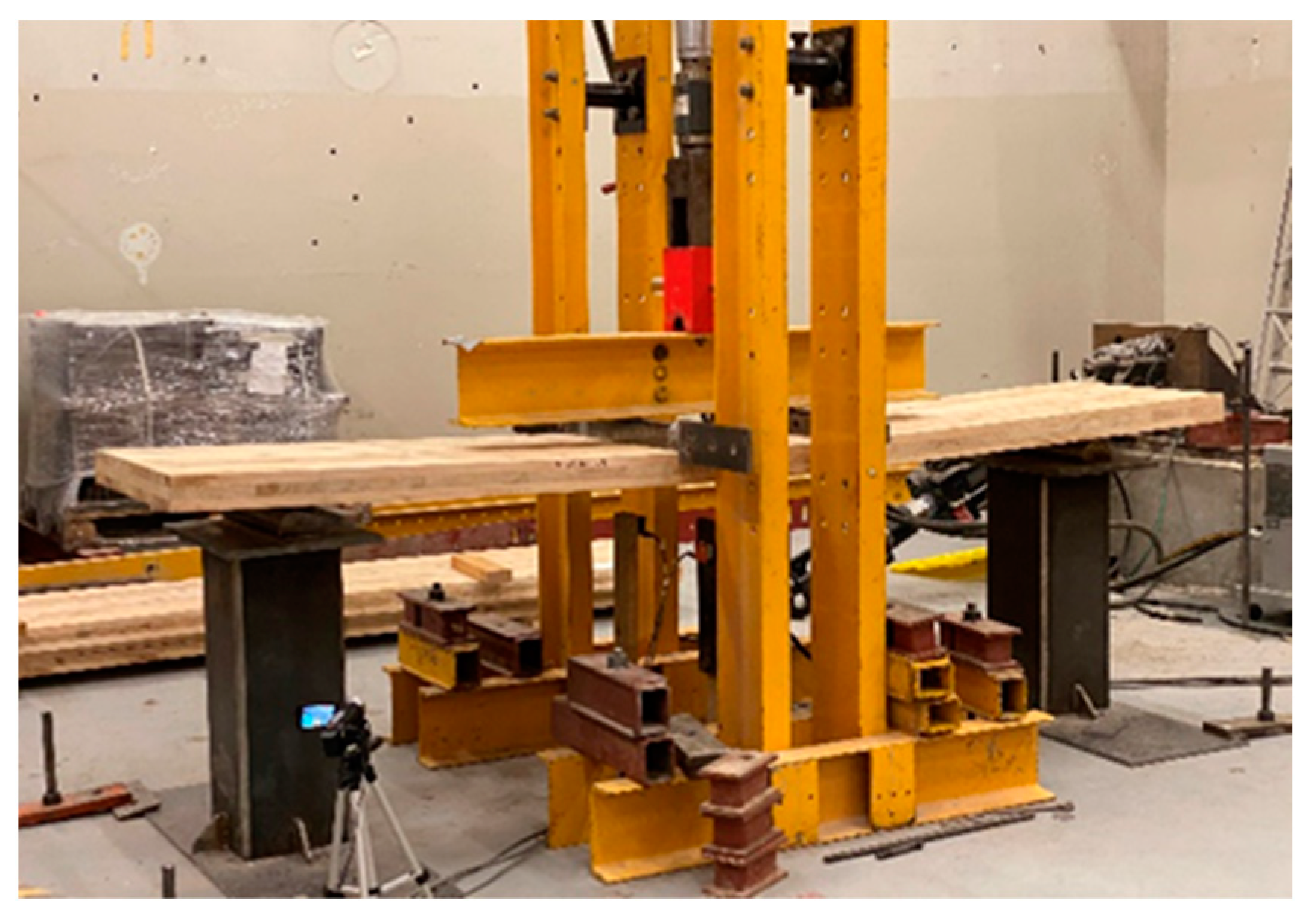
2.6.1. Out-Of-Plane Bending Tests
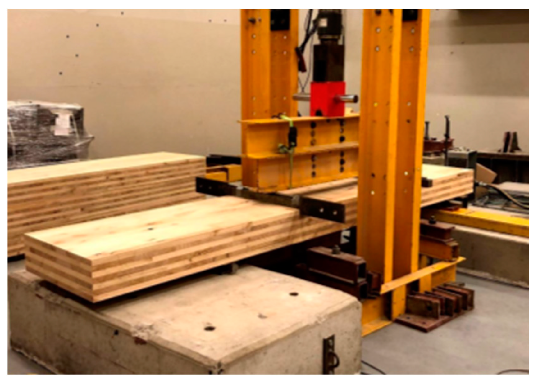
2.6.2. Rolling Shear Tests in Bending
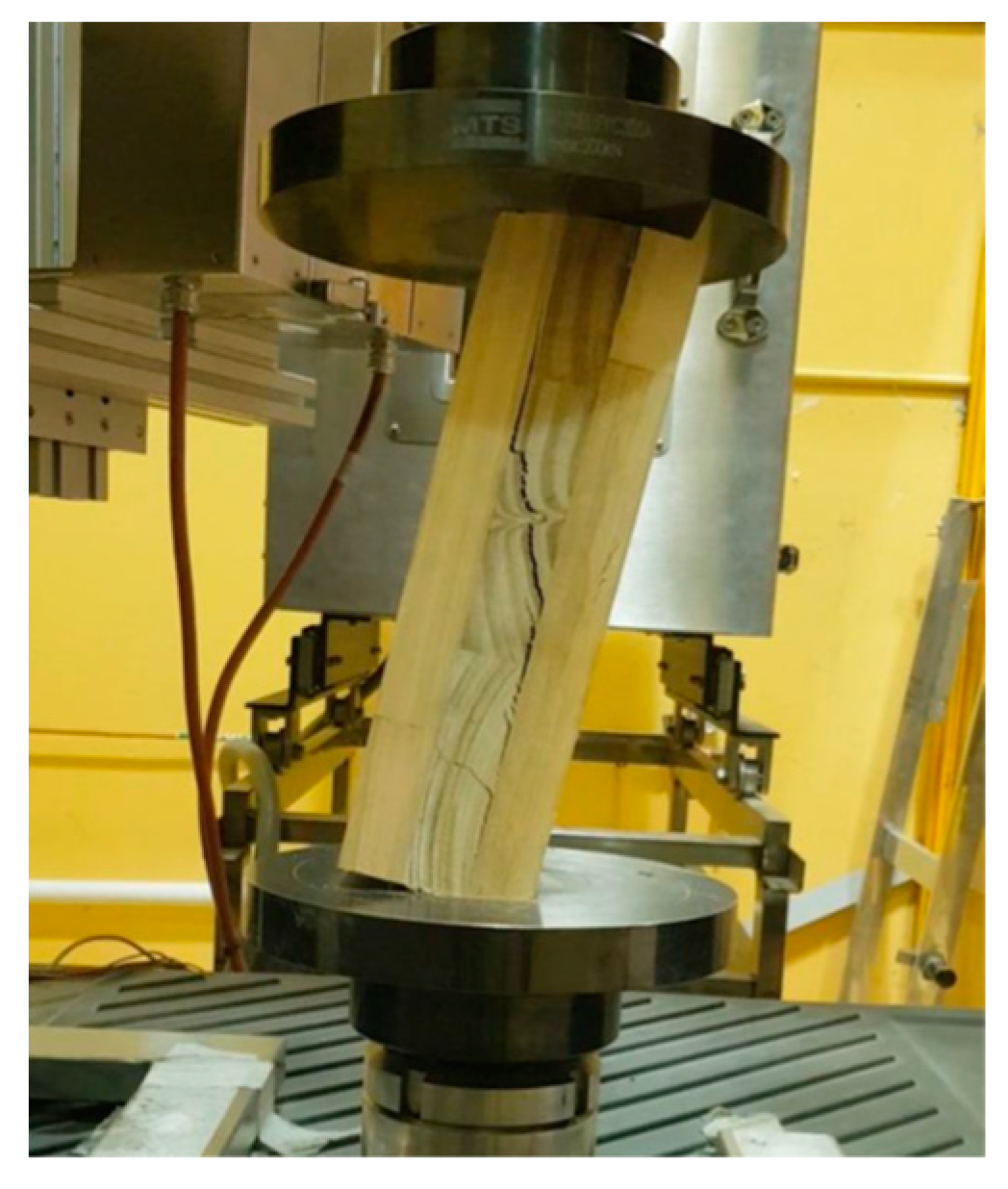
2.6.3. Pure Rolling Shear Tests
2.7. Modelling CLT Mechanical Properties
3. Results
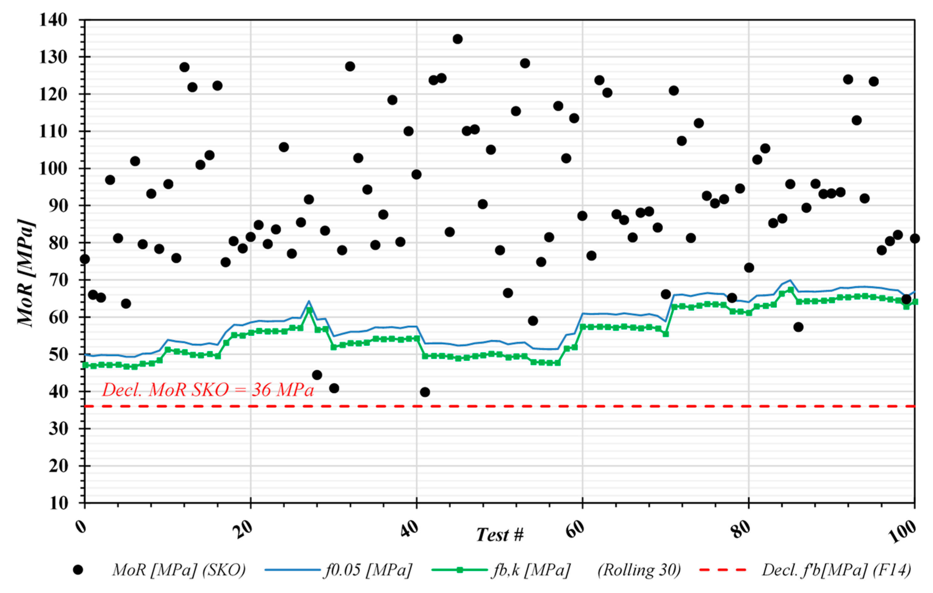
3.1. Solid and Finger-Jointed Timber Strength and Stiffness
3.2. CLT Bending Strength Out-Of-Plane
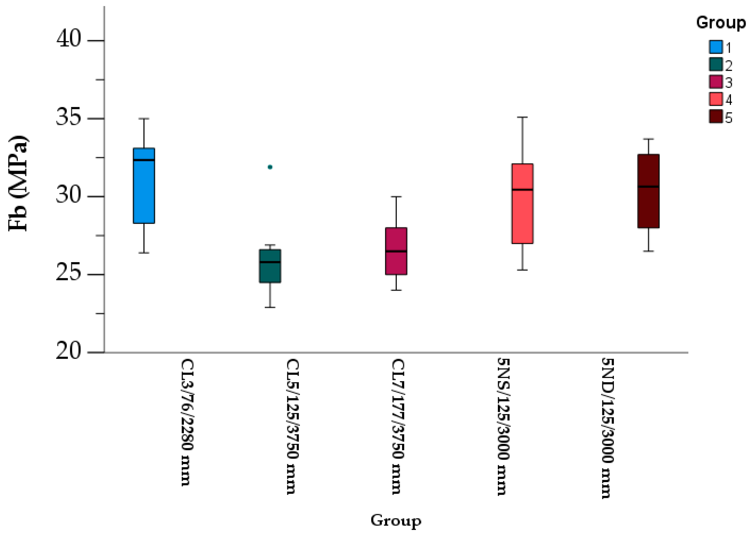
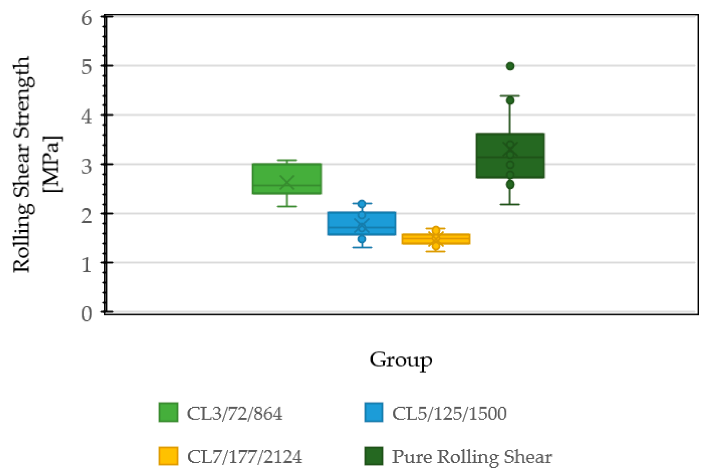
3.3. CLT Rolling Shear Strength
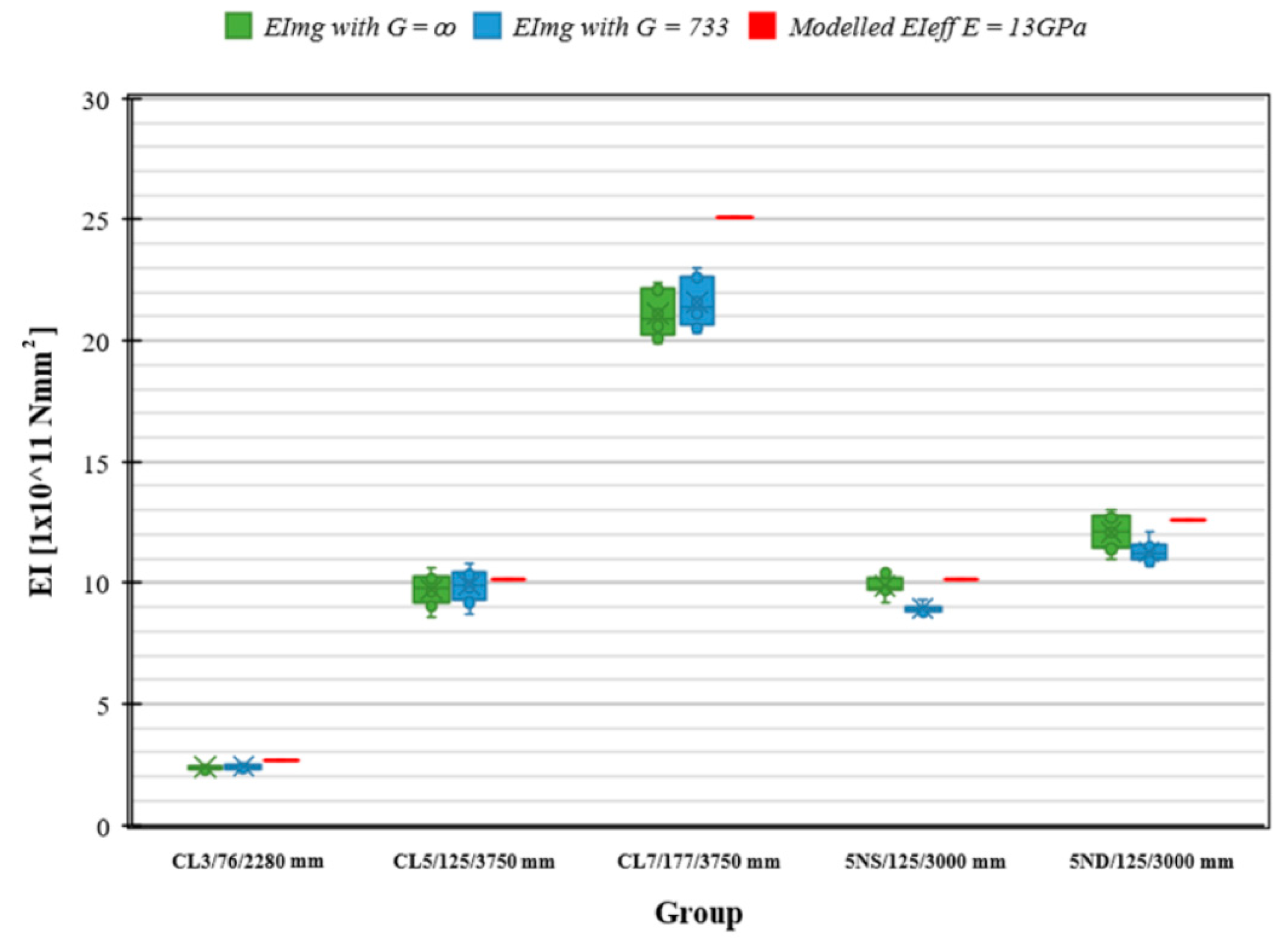
3.4. Experimental and Modelled Bending Stiffness (EI)
4. Discussion
5. Conclusions
Author Contributions
Funding
Data Availability Statement
Conflicts of Interest
References
- Legg, P.; Frakes, I.; Gavran, M. Australian Plantation Statistics and Log Availability Report 2021; ABARES research report; Australian Bureau of Agricultural and Resource Economics and Sciences: Canberra, Australia, 2021. [CrossRef]
- Australian Forest Products Association. Australia Faces a Critical Housing Timber Shortage by 2050: FWPA Report. 2022. Available online: https://ausfpa.com.au/australia-faces-a-critical-housing-timber-shortage-by-2050-fwpa-report/ (accessed on 1 November 2022).
- Kurzinski, S.; Crovella, P.; Kremer, P. Overview of Cross-Laminated Timber (CLT) and Timber Structure Standards Across the World. Mass Timber Constr. J. 2022, 5, 1–13. Available online: https://www.journalmtc.com/index.php/mtcj/article/view/29 (accessed on 1 November 2022).
- Ettelaei, A.; Taoum, A.; Shanks, J.; Nolan, G. Evaluation of the bending properties of novel cross-laminated timber with different configurations made of Australian plantation Eucalyptus nitens using experimental and theoretical methods. Structures 2022, 42, 80–90. [Google Scholar] [CrossRef]
- Ettelaei, A.; Taoum, A.; Nolan, G. Assessment of Different Measurement Methods/Techniques in Predicting Modulus of Elasticity of Plantation Eucalyptus nitens Timber for Structural Purposes. Forests 2022, 13, 607. [Google Scholar] [CrossRef]
- Ettelaei, A.; Taoum, A.; Shanks, J.; Nolan, G. Rolling Shear Properties of Cross-Laminated Timber Made from Australian Plantation Eucalyptus nitens under Planar Shear Test. Forests 2022, 13, 84. [Google Scholar] [CrossRef]
- Ettelaei, A.; Taoum, A.; Nolan, G. Rolling shear properties of cross-laminated timber made of fibre-managed plantation eucalyptus under short-span bending. Wood Mater. Sci. Eng. 2021, 17, 744–751. [Google Scholar] [CrossRef]
- Derikvand, M.; Jiao, H.; Kotlarewski, N.; Lee, M.; Chan, A.; Nolan, G. Bending performance of nail-laminated timber constructed of fast-grown plantation eucalypt. Eur. J. Wood Wood Prod. 2019, 77, 421–437. [Google Scholar] [CrossRef]
- Derikvand, M.; Kotlarewski, N.; Lee, M.; Jiao, H.; Chan, A.; Nolan, G. Short-term and long-term bending properties of nail-laminated timber constructed of fast-grown plantation eucalypt. Constr. Build. Mater. 2019, 211, 952–964. [Google Scholar] [CrossRef]
- Derikvand, M.; Kotlarewski, N.; Lee, M.; Jiao, H.; Nolan, G. Characterisation of physical and mechanical properties of unthinned and unpruned plantation-grown Eucalyptus nitens H. Deane & Maiden lumber. Forests 2019, 10, 194. [Google Scholar]
- Derikvand, M.; Bignell, M.; Balasso, M.; Kotlarewski, N.; Jiao, H.; Lee, M.; Nolan, G. Multi-disciplinary optimisation of nail-laminated timber-concrete composite panels constructed of fibre-managed plantation eucalypt. In Proceedings of the 61st International Convention of Society of Wood Science and Technology and Japan Wood Research Society, Nagoya, Japan, 5–9 November 2018; pp. 1–6. [Google Scholar]
- Derikvand, M.; Kotlarewski, N.; Lee, M.; Jiao, H.; Chan, A.; Nolan, G. Visual stress grading of fibre-managed plantation Eucalypt timber for structural building applications. Constr. Build. Mater. 2018, 167, 688–699. [Google Scholar] [CrossRef]
- Derikvand, M.; Nolan, G.; Jiao, H.; Kotlarewski, N. What to do with structurally low-grade wood from Australia’s plantation eucalyptus; building application? BioResources 2017, 12, 4–7. [Google Scholar] [CrossRef] [Green Version]
- Jiao, H.; Nolan, G.; Lee, M.; Kotlarewski, N.; Derikvand, M. Developing High-Mass Laminated Flooring Products from Fibre-Managed Plantation Hardwood; Forest & Wood Products Australia: Melbourne, Australia, 2019. [Google Scholar]
- Kotlarewski, N.J.; Derikvand, M.; Lee, M.; Whiteroad, I. Machinability study of Australia’s dominate plantation timber resources. Forests 2019, 10, 805. [Google Scholar] [CrossRef]
- Kotlarewski, N.; Taylor, L.; Booth, P. Embracing natural timber features of plantation hardwood: Material-aware digital workflows in product design and development. In Proceedings of the 52nd International Conference of the Architectural Science Association (ANZAScA) Engaging Architectural Science: Meeting the Challenges of Higher Density, Melbourne, Australia, 28 November–1 December 2018. [Google Scholar]
- Pangh, H.; Hosseinabadi, H.Z.; Kotlarewski, N.; Moradpour, P.; Lee, M.; Nolan, G. Flexural performance of cross-laminated timber constructed from fibre-managed plantation eucalyptus. Constr. Build. Mater. 2019, 208, 535–542. [Google Scholar] [CrossRef]
- Gutierrez, M.; Kotlarewski, N.; Lee, M. Mass Timber Alternatives in Construction with Plantation Hardwoods. In Proceedings of the 2022 SWST International Conference, Kingscliff, Australia, 10–15 July 2022; pp. 33–41. [Google Scholar]
- Ehrhart, T.; Brandner, R. Rolling shear: Test configurations and properties of some European soft-and hardwood species. Eng. Struct. 2018, 172, 554–572. [Google Scholar] [CrossRef]
- Niederwestberg, J.; Zhou, J.; Chui, Y.-H. Comparison of Theoretical and Laboratory Out-of-Plane Shear Stiffness Values of Cross Laminated Timber Panels. Buildings 2018, 8, 146. [Google Scholar] [CrossRef] [Green Version]
- Ma, Y.; Musah, M.; Si, R.; Dai, Q.; Xie, X.; Wang, X.; Ross, R.J. Integrated experimental and numerical study on flexural properties of cross laminated timber made of low-value sugar maple lumber. Constr. Build. Mater. 2021, 280, 122508. [Google Scholar] [CrossRef]
- Mohd Yusof, N.; Md Tahir, P.; Lee, S.H.; Khan, M.A.; Mohammad Suffian James, R. Mechanical and physical properties of Cross-Laminated Timber made from Acacia mangium wood as function of adhesive types. J. Wood Sci. 2019, 65, 20. [Google Scholar] [CrossRef] [Green Version]
- Hindman, D.P.; Bouldin, J.C. Mechanical Properties of Southern Pine Cross-Laminated Timber. J. Mater. Civ. Eng. 2015, 27, 04014251. [Google Scholar] [CrossRef]
- O’Ceallaigh, C.; Sikora, K.; Harte, A. The Influence of Panel Lay-Up on the Characteristic Bending and Rolling Shear Strength of CLT. Buildings 2018, 8, 114. [Google Scholar] [CrossRef] [Green Version]
- Li, X.; Ashraf, M.; Subhani, M.; Kremer, P.; Kafle, B.; Ghabraie, K. Experimental and numerical study on bending properties of heterogeneous lamella layups in cross laminated timber using Australian Radiata Pine. Constr. Build. Mater. 2020, 247, 118525. [Google Scholar] [CrossRef]
- Navaratnam, S.; Christopher, P.B.; Ngo, T.; Le, T.V. Bending and shear performance of Australian Radiata pine cross-laminated timber. Constr. Build. Mater. 2020, 232, 117215. [Google Scholar] [CrossRef]
- Li, X.; Ashraf, M.; Subhani, M.; Kremer, P.; Li, H.; Anwar-Us-Saadat, M. Rolling shear properties of cross-laminated timber (CLT) made from Australian Radiata Pine—An experimental study. Structures 2021, 33, 423–432. [Google Scholar] [CrossRef]
- Liao, Y.; Tu, D.; Zhou, J.; Zhou, H.; Yun, H.; Gu, J.; Hu, C. Feasibility of manufacturing cross-laminated timber using fast-grown small diameter eucalyptus lumbers. Constr. Build. Mater. 2017, 132, 508–515. [Google Scholar] [CrossRef]
- Nero, R.; Christopher, P.; Ngo, T. Investigation of rolling shear properties of cross-laminated timber (CLT) and comparison of experimental approaches. Constr. Build. Mater. 2022, 316, 125897. [Google Scholar] [CrossRef]
- BS EN, 16351; Timber Structures—Cross-Laminated Timber—Requirements. British Standard: London, UK, 2015.
- ANSI/APA PRG 320; Standard for Performance-Rated Cross-Laminated Timber. American National Standard: Washington, DC, USA, 2020.
- Ammann, S.; Schlegel, S.; Beyer, M.; Aehlig, K.; Lehmann, M.; Jung, H.; Niemz, P. Quality assessment of glued ash wood for construction engineering. Eur. J. Wood Wood Prod. 2016, 74, 67–74. [Google Scholar] [CrossRef]
- Fink, G.; Kohler, J.; Brandner, R. Application of European design principles to cross laminated timber. Eng. Struct. 2018, 171, 934–943. [Google Scholar] [CrossRef]
- Forest Products Laboratory. Finger-Jointed Wood Products; Research Paper FPL 382; US Department of Agriculture, Forest Service, Forest Products Laboratory: Madison, WI, USA, 1981.
- Özçifçi, A.; Yapıcı, F. Structural performance of the finger-jointed strength of some wood species with different joint configurations. Constr. Build. Mater. 2008, 22, 1543–1550. [Google Scholar] [CrossRef]
- Bustos, C.; Beauregard, R.; Mohammad, M.; Hernández, R.E. Structural performance of finger-jointed black spruce lumber with different joint configurations. For. Prod. J. 2003, 53, 72–76. [Google Scholar]
- Bustos, C.; Hernández, R.E.; Beauregard, R.; Mohammad, M. Influence of machining parameters on the structural performance of finger-joined black spruce. Wood Fiber Sci. 2004, 359–367. [Google Scholar]
- Rao, S.; Gong, M.; Chui, Y.H.; Mohammad, M. Effect of end pressure on performance of structural finger-joined lumber fabricated using a short joint profile. Eur. J. Wood Wood Prod. 2014, 72, 143–145. [Google Scholar] [CrossRef]
- Frangi, A.; Bertocchi, M.; Clauß, S.; Niemz, P. Mechanical behaviour of finger joints at elevated temperatures. Wood Sci. Technol. 2012, 46, 793–812. [Google Scholar] [CrossRef]
- Habipi, B.; Ajdinaj, D. Wood finger-joint strength as function of finger length and slope positioning of tips. Int. J. Eng. Appl. Sci. 2015, 2, 257757. [Google Scholar]
- Lara-Bocanegra, A.J.; Majano-Majano, A.; Crespo, J.; Guaita, M. Finger-jointed Eucalyptus globulus with 1C-PUR adhesive for high performance engineered laminated products. Constr. Build. Mater. 2017, 135, 529–537. [Google Scholar] [CrossRef]
- Nogueira, R.D.S.; Moritani, F.Y.; Icimoto, F.H.; Dias, A.A.; Calil, C. Performance of one-component polyurethane (1C-PUR) adhesives in the production of finger-joints fabricated from four planted forest species. Eur. J. Wood Wood Prod. 2022, 80, 1421–1431. [Google Scholar] [CrossRef]
- Muthumala, C.K.; De Silva, S.; Alwis, P.L.A.G.; Arunakumara, K.K.I.U. Identification of the best finger joint configuration for Sri Lankan wood species based on the flexural strength. J. Indian Acad. Wood Sci. 2021, 18, 89–96. [Google Scholar] [CrossRef]
- Piao, C.; Monlezun, C.J.; Groom, L.; Gibson, M.D. Mechanical properties of finger-jointed round wood cores. Int. Wood Prod. J. 2013, 4, 107–115. [Google Scholar] [CrossRef]
- Baño, V.; Godoy, D.; Figueredo, D.; Vega, A. Characterization and structural performance in bending of CLT panels made from small-diameter logs of loblolly/slash pine. Materials 2018, 11, 2436. [Google Scholar] [CrossRef] [PubMed] [Green Version]
- Franke, B.; Schusser, A.; Müller, A. Analysis of finger joints from beech wood. In Proceedings of the World Conference in Timber Engineering WCTE 2014, Quebec City, QC, Canada, 10–14 August 2014. [Google Scholar]
- AS/NZS 43642010 Timber—Bond Performance of Structural Adhesives; Standards Australia and New Zealand: Sydney, Australia, 2010.
- Timber—Finger Joints in Structural Products—Production Requirements. AS/NZS5068:2006Standards Australia and New Zealand: Sydney, Australia, 2006.
- ISO 16696-1; Timber Structures—Cross Laminated Timber—Part 1: Component Performance, Production Requirements and Certification Scheme 2016. International Standardization Organization: Geneva, Switzerland, 2019.
- AS/NZS 4063.12010 Structural Timber—Characteristic Values of Strength Graded Timber; Standards Australia and Standards New Zealand: Sydney, Australia; Wellington, New Zealand, 2010.
- EN408 2012; Timber Structures: Structural Timber and Glue-Laminated Timber Determination of Some Physical and Mechanical Properties. German Institute for Standardisation: Berlin, Germanay, 2012.
- Karacabeyli, E.; Douglas, B. CLT handbook: Cross-laminated timber, US edition, FPInnovations. Can. J. Fish. Aquat. Sci. 2013, 70, 59. [Google Scholar]
- AS/NZS 4063.2Characterization of Structural Timber—Part 2: Determination of Characteristic Values; Standards Australia and New Zealand: Sydney, Australia, 2010.
- He, M.; Sun, X.; Ren, H.; Li, Z.; Feng, W. Experimental study on the system effect of bending cross-laminated timber fabricated with Karamatsu larch. Constr. Build. Mater. 2021, 299, 124271. [Google Scholar] [CrossRef]
- Steiger, R.; Gülzow, A.; Czaderski, C.; Howald, M.T.; Niemz, P. Comparison of bending stiffness of cross-laminated solid timber derived by modal analysis of full panels and by bending tests of strip-shaped specimens. Eur. J. Wood Wood Prod. 2012, 70, 141–153. [Google Scholar] [CrossRef]
- EN15425:2017; Adhesives—One Component Polyurethane (PUR) for Load-Bearing Timber Structures—Classification and Performance Requirements. CEN: Brussels, Belgium, 2017.
- Breneman, S. CLT Floor Design: Strength, Deflection and Vibrations; 2014. Available online: https://dokumen.tips/documents/clt-floor-design-strength-deflection-and-vibrations-a-clt-floor-design.html?page=1 (accessed on 18 November 2022).


| Panel Identifier | Finger Joint Length (mm) | Number of Layers | Nominal Thickness (mm) | Bending Test Span (mm) | Configuration |
|---|---|---|---|---|---|
| CL3 | 10 | 3 | 75 | 2280 | Traditional CLT |
| CL5 | 10 | 5 | 125 | 3750 | Traditional CLT |
| CL7 | 10 | 7 | 175 | 3750 | Traditional CLT |
| 5NS | 15 | 5 | 125 | 3000 | Traditional CLT |
| 5ND | 15 | 5 | 125 | 3000 | Double outer lamella layers oriented longitudinally |
| Mechanical Properties | Average Result [MPa] | n | SD [MPa] | Manufacturer’s Declared Value [MPa] |
|---|---|---|---|---|
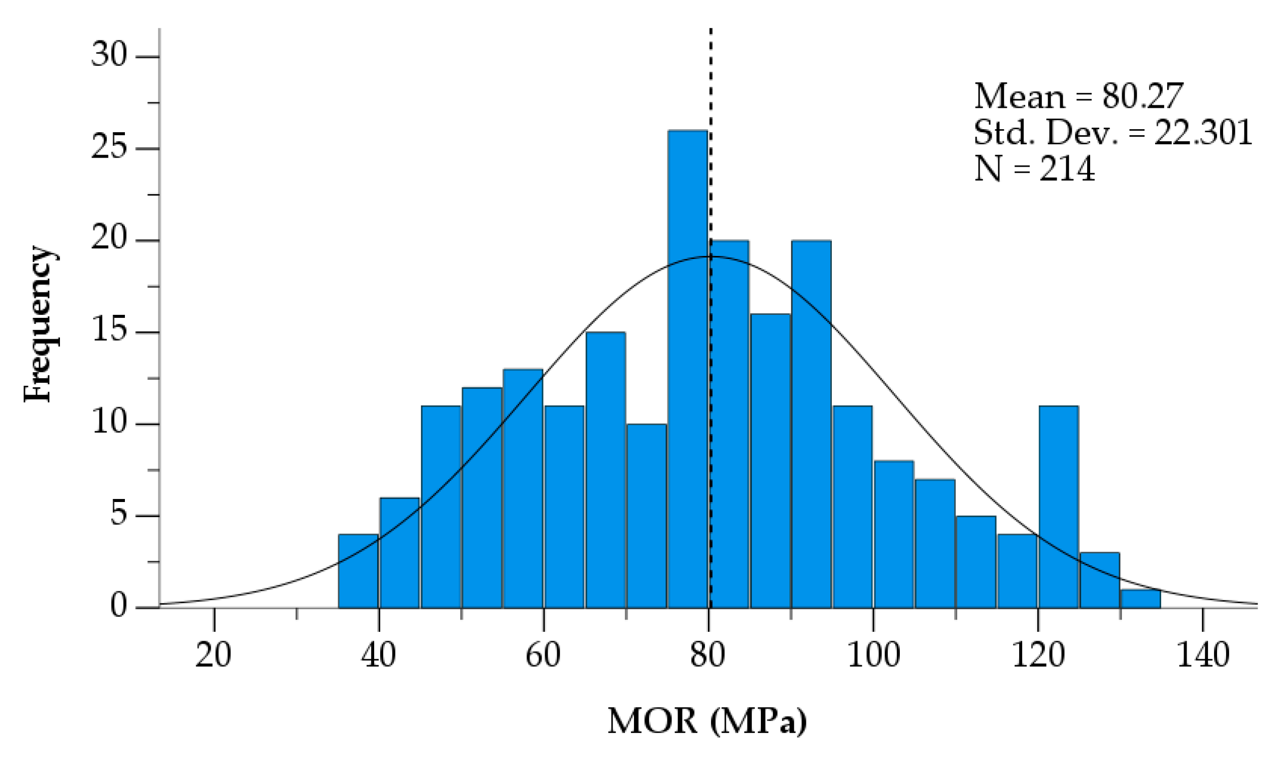
| Bending strength solid timber, fb | 80.3 | 214 | 22.3 | 36.0 |
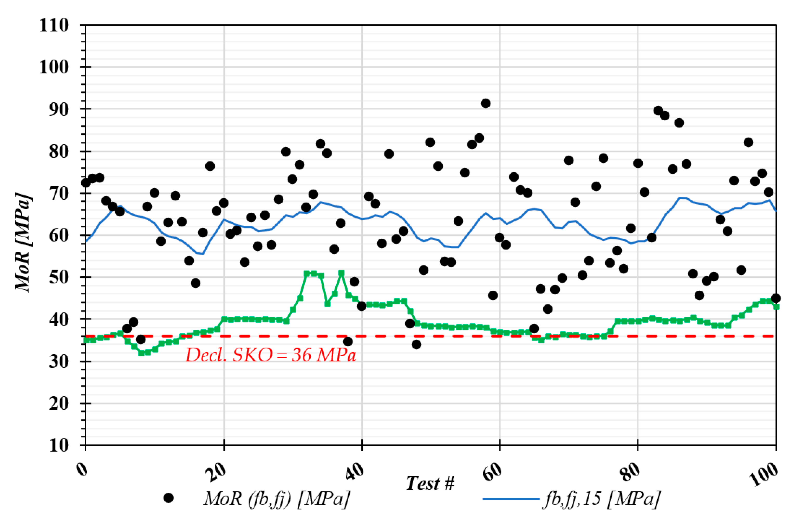
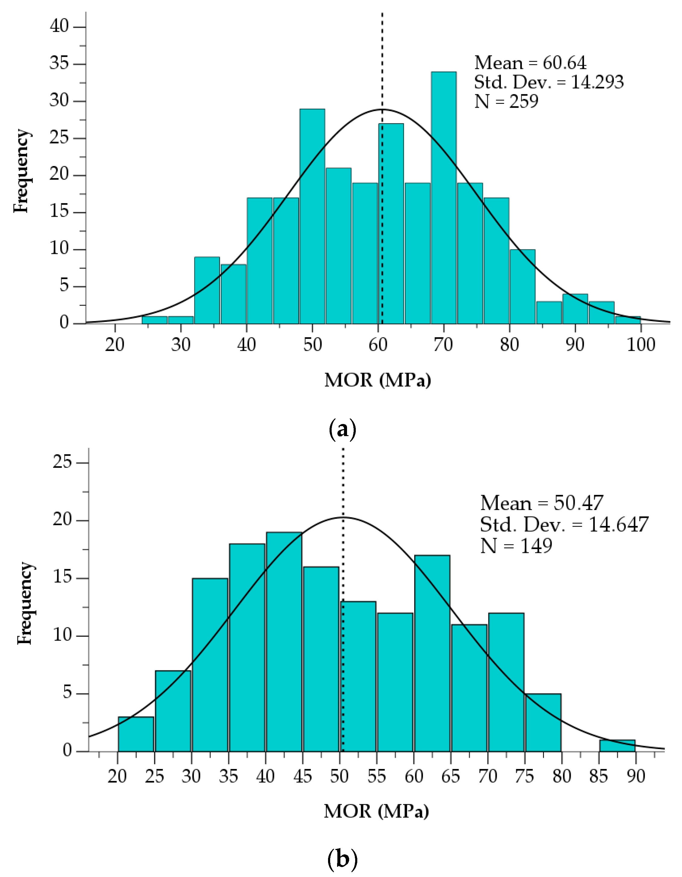
| Bending strength finger joints on longitudinal lamellas (finger length = 15 mm), fb,fj | 60.6 | 259 | 14.3 | 36.0 |
| Bending strength finger joints on crossed lamellas, fb,fj | 50.5 | 149 | 14.6 | 25.0 |
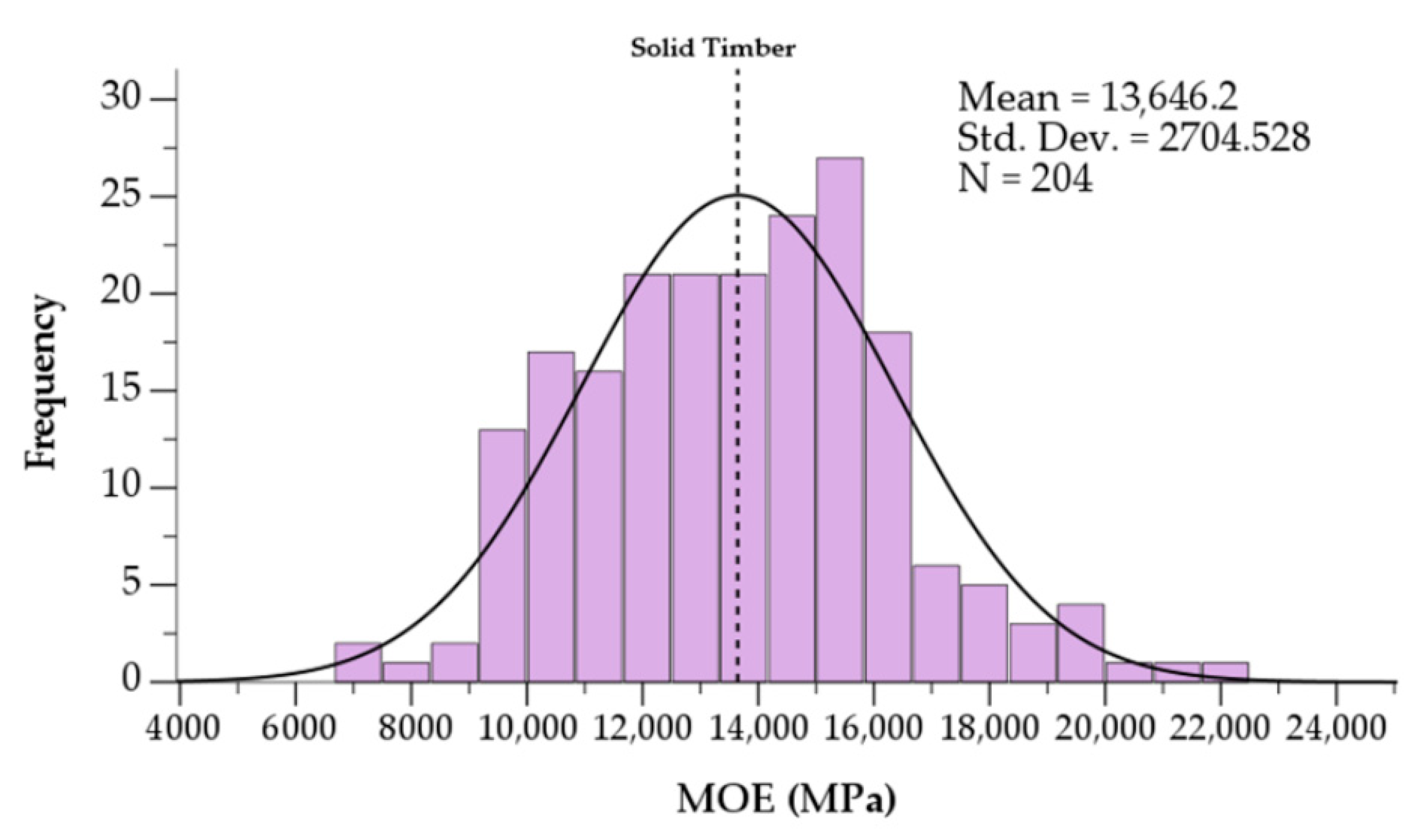
| Modulus of elasticity of longitudinal boards, E | 13,646 | 204 | 2076 | 13,000 |
| Mechanical Properties | Average Result [MPa] | n | SD [MPa] | Manufacturer’s Declared Value [MPa] |
|---|---|---|---|---|
| CLT bending strength, fb | 28.9 | 49 | 3.3 | 24.0 |
| CLT rolling shear strength by bending tests, frv | 1.9 | 27 | 0.5 | Rejected due to bending failure |
| CLT rolling shear strength by pure rolling shear tests, frv | 3.3 | 14 | 0.7 | 2.0 |
| Modulus of elasticity of longitudinal boards, E | 13,646 | 204 | 2076 | 13,000 |
Disclaimer/Publisher’s Note: The statements, opinions and data contained in all publications are solely those of the individual author(s) and contributor(s) and not of MDPI and/or the editor(s). MDPI and/or the editor(s) disclaim responsibility for any injury to people or property resulting from any ideas, methods, instructions or products referred to in the content. |
© 2023 by the authors. Licensee MDPI, Basel, Switzerland. This article is an open access article distributed under the terms and conditions of the Creative Commons Attribution (CC BY) license (https://creativecommons.org/licenses/by/4.0/).
Share and Cite
Gutierrez, M.; Ettelaei, A.; Kotlarewski, N.; Lee, M. Structural Properties of Commercial Australian Plantation Hardwood CLT. Buildings 2023, 13, 208. https://doi.org/10.3390/buildings13010208
Gutierrez M, Ettelaei A, Kotlarewski N, Lee M. Structural Properties of Commercial Australian Plantation Hardwood CLT. Buildings. 2023; 13(1):208. https://doi.org/10.3390/buildings13010208
Chicago/Turabian StyleGutierrez, Mateo, Azin Ettelaei, Nathan Kotlarewski, and Michael Lee. 2023. "Structural Properties of Commercial Australian Plantation Hardwood CLT" Buildings 13, no. 1: 208. https://doi.org/10.3390/buildings13010208