1. Introduction
Currently, the use of natural, renewable, and easily recyclable materials as building materials is still becoming more popular. Enhancing environmental requirements and long-term sustainability in construction is an increasingly discussed topic. Timber structures, which are commonly used as a substitute for steel and concrete structures, considerably mitigate the impact on the environment thanks to their smaller carbon footprint and thus significantly contribute to sustainability in civil engineering [
1].
However, timber structures have limits to their use, especially for buildings with a large height (multi-story buildings) [
2]. Standard timber elements, such as beams, joist, purlins and columns, can be also used for multi-story buildings, but it is necessary to realize strong stiffening in the horizontal direction. CLT panels are timber products, which can be used for vertical and horizontal load-carrying structures. CLT panels have very good mechanical properties [
3]. CLT panels are area structural elements, and they can transport vertical and horizontal forces and act as key stiffening members of the whole structure. They are often used for modular construction [
4].
Cross-laminated timber (CLT) is a large-format building component composed of cross-oriented solid timber layers. CLT panels are usually composed of 3 to 7 layers (see
Figure 1). These layers are glued together, usually in all directions. Polyurethane adhesives are mostly used for gluing them [
5]. They are connected using so-called finger joints in the longitudinal direction [
6]. There are also different ways of connecting individual panels using mechanical fasteners [
7]. CLT panels are often made of spruce [
8], but they can also be made of pine or other coniferous timber [
5,
9,
10]. A number of publications discuss their properties, practical use and general design principles [
11,
12,
13].
The timber is dried at a moisture content in the range of 8% to 12% during production, which enables high resistance against atmospheric influences and prevents unexpected cracking. CLT panels offer reliable dimensional stability even in the case of significant changes in the humidity of the environment [
14].
CLT panels are made of timber, and therefore this material is flammable [
15,
16]. Based on the fire tests, CLT panels are classified as class D according to their reaction to fire. Fire resistance describes how long a CLT panel is able to withstand the effects of flame. CLT panels are usually used as load-carrying structures, and therefore we denote a fire resistance REI [
17]. The fire resistance REI of a horizontal five-layer CLT panel with a thickness of 140 mm is 60 min [
18]. Mentioned information about the fire resistance of CLT panels was defined on the basis of large-scale fire tests [
19].
CLT panels are sometimes used in the construction of modern buildings, especially passive and zero-energy houses. CLT panel is a solid material and therefore is air-thickness. Of course, it is necessary to provide tight connections between individual panels and other details. CLT panels have relatively higher diffusion resistance [
20]. The diffusion equivalent of CLT reduces water vapor amount with diffuses from external structures and reduces the amount of interstitial condensation [
21]. The next advantage of CLT panels is high heat capacity [
22]. High heat capacity can affect the thermal stability of building interiors because materials with high thermal capacity can accumulate heat or cold. The accumulation of heat or cold slows down the rise or fall in air temperature in building interiors.
CLT panels are also popular for their excellent strength and stiffness characteristics because they significantly influence the dimensions of load-carrying elements and the static design of the entire structure. These properties are mainly given by the material and geometric characteristics of individual lamellae [
23]. Some researchers investigated the effect of lamella thickness [
8,
24] or panel width [
25,
26] on bending behavior. Another publication dealt with experimental bending tests of a panel with spacings in the transverse layer [
27]. Experimentally obtained data on bending stiffness and bending strength were verified by numerical models [
26,
28] or using probabilistic methods [
29].
Several approaches can be used for the analytical calculation of the bending stiffness of CLT panels. The most used methods are the composite method (K-method) [
30], the gamma method [
31,
32] or the shear analogy method [
33]. Details and a comparison of those methods are given in the publication [
34].
Thanks to many positive properties, CLT panels are currently used in the construction of civil and residential buildings (ceilings, roofs and walls) [
35]. They are often used for the construction of multi-story buildings due to their higher horizontal stiffness [
36,
37] and also resistance to seismic effects [
38] compared to traditional timber buildings. Last but not least, they can be combined with other structural systems (e.g., concrete structures) [
39]. An alternative option to CLT can also be panels from laminated veneer lumber [
40].
Since CLT panels are widely used for the construction of horizontal load-carrying elements (ceilings), it is important to know their strength and stiffness properties in bending. Structural engineers are often only dependent on the selected analytical procedures according to design standards and do not have relevant knowledge from experimental testing and numerical modeling of these load-carrying elements.
The aim of the research was to carry out static tests on several types of CLT panels made of Nordic spruce (Picea Sitchensis). Individual types differed in the total thickness and number of layers (three, five or seven layers). The specimens were subjected to four-point bending tests to determine their local and global stiffnesses in bending. The experimentally obtained data were compared with an analytical calculation of the bending stiffness using the gamma method given in the European standard for the design of timber structures [
32], which was modified for glued structural elements [
34]. Scientific discourse focuses exclusively on five-layer CLT panels. At the same time, no attention is paid to the three-layer and seven-layer CLT panels, which are quite innovative, but increasingly used in practical applications. The dimensions, composition and geometry of the CLT panels were based on the specific requirements of the manufacturer of these load-carrying elements. There is no reference that deals with the same types of CLT panels. It was therefore necessary to verify experimentally and theoretically their response to the load and possible modes of failure, which could be a valuable contribution to this research area. The results showed a good agreement in the bending behavior between the laboratory tests and the analytical calculation according to the standard.
The aim was also to outline the methods of numerical modeling of multi-layer cross-laminated structural elements made of glued timber, using two completely different approaches in commercial software, ANSYS Workbench and SCIA Engineer. ANSYS Workbench uses 3D finite elements and is not commonly available to the general public in the construction practice, whereas SCIA Engineer is a software tool for engineers who design building structures in the construction practice. Numerical models in SCIA Engineer use beam and shell finite elements with orthotropy, which has proven to be a fast and accurate alternative to numerical analysis in ANSYS Workbench. These insights and approaches could then be used in practice by structural engineers. The results showed a good agreement in the bending behavior between the laboratory tests and both approaches in numerical analysis.
2. Materials and Methods
The deformation analysis primarily included the determination of the stiffness parameters (local and global moduli of elasticity in bending) of the CLT panels based on the experimental laboratory tests. These results were used for the analytical calculation of the mid-span deflections and for comparison with the theoretical value according to the standard [
32], actual measured values and numerical analysis. The tests proceeded according to the principles given in [
41,
42,
43]. There were deviations in the geometry and composition of some specimens compared to the recommendations and requirements in the above-mentioned standards (3 or 7 layers instead of the common 5 layers, panel width of 500 mm) based on the specific requirements of the supplier of the specimens (wishes to remain anonymous). However, all tested types of panels are sometimes used in construction practice in central and northern Europe. All the experiments were conducted in the laboratory of the Technical and Test Institute for Construction Prague, Ostrava Branch using steel testing equipment and Datalogger Ahlborn ALMEMO 710 (Ahlborn Mess- und Regelungstechnik GmbH, Holzkirchen, Germany).
Moisture content measurements were carried out before the main test. Moisture contents were measured using a capacitive material moisture meter, Brookhuis FMW-B (Brookhuis Applied Data Intelligence, Enschede, The Netherlands), with an accuracy of ±0.5% according to [
44]. All specimens were tested at approximately equilibrium moisture content in a dry interior (average 11.8%, standard deviation 0.2%). The air temperature was 20 °C, and relative air humidity was 65%, according to a meteorological station, GoGEN ME 3900 (ETA a.s., Praha, The Czech Republic).
2.1. Description of Specimens and Experimental Laboratory Tests
Three different types of CLT panels were selected for the testing—CLT 140-3; CLT 160-5; 240-7-2. The panel CLT 140-3 consisted of 3 layers with a total thickness of 140 mm (see
Figure 2): the outer layers (40 mm thick) were laid in the longitudinal direction, and the middle layer (60 mm thick) was laid in the transverse direction. The panel CLT 160-5 consisted of 5 layers with a total thickness of 160 mm (see
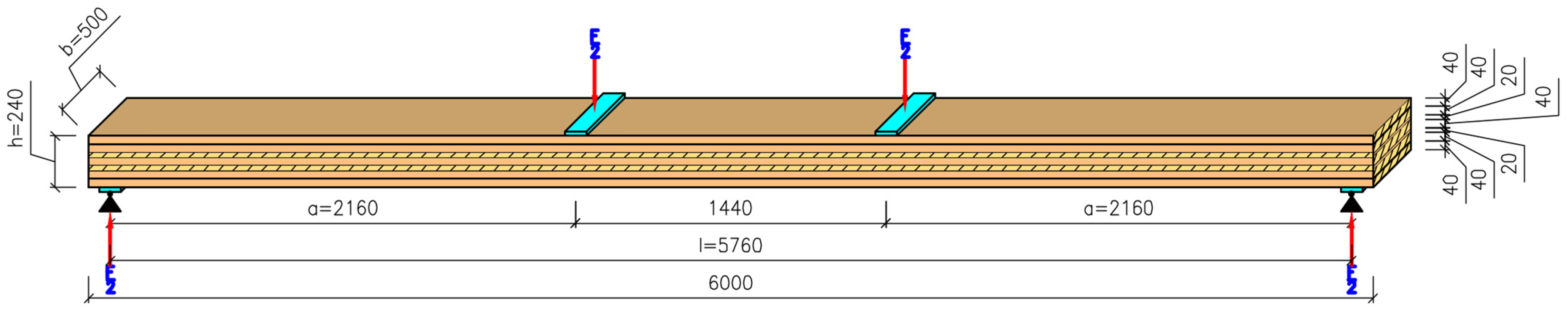
Figure 3): the outer layers and the middle layer (40 mm thick) were laid in the longitudinal direction, and the intermediate layers (20 mm thick) were laid in the transverse direction. The panel CLT 240-7-2 consisted of 7 layers with a total thickness of 240 mm (see
Figure 4): the two outer layers and the middle layer (40 mm thick) were laid in the longitudinal direction, and the intermediate layers (20 mm thick) were laid in the transverse direction.
All the layers were made of Nordic spruce of C24 strength class (determined based on visual grading according to [
45]). The layers were glued together with a polyurethane adhesive at elevated pressure, constant temperature and constant humidity. The width of individual laminae in one layer was 200 mm or 100 mm. The geometrical specification of all tested types of panels and the corresponding test arrangements are shown in
Figure 2,
Figure 3 and
Figure 4 (all the dimensions are in millimeters).
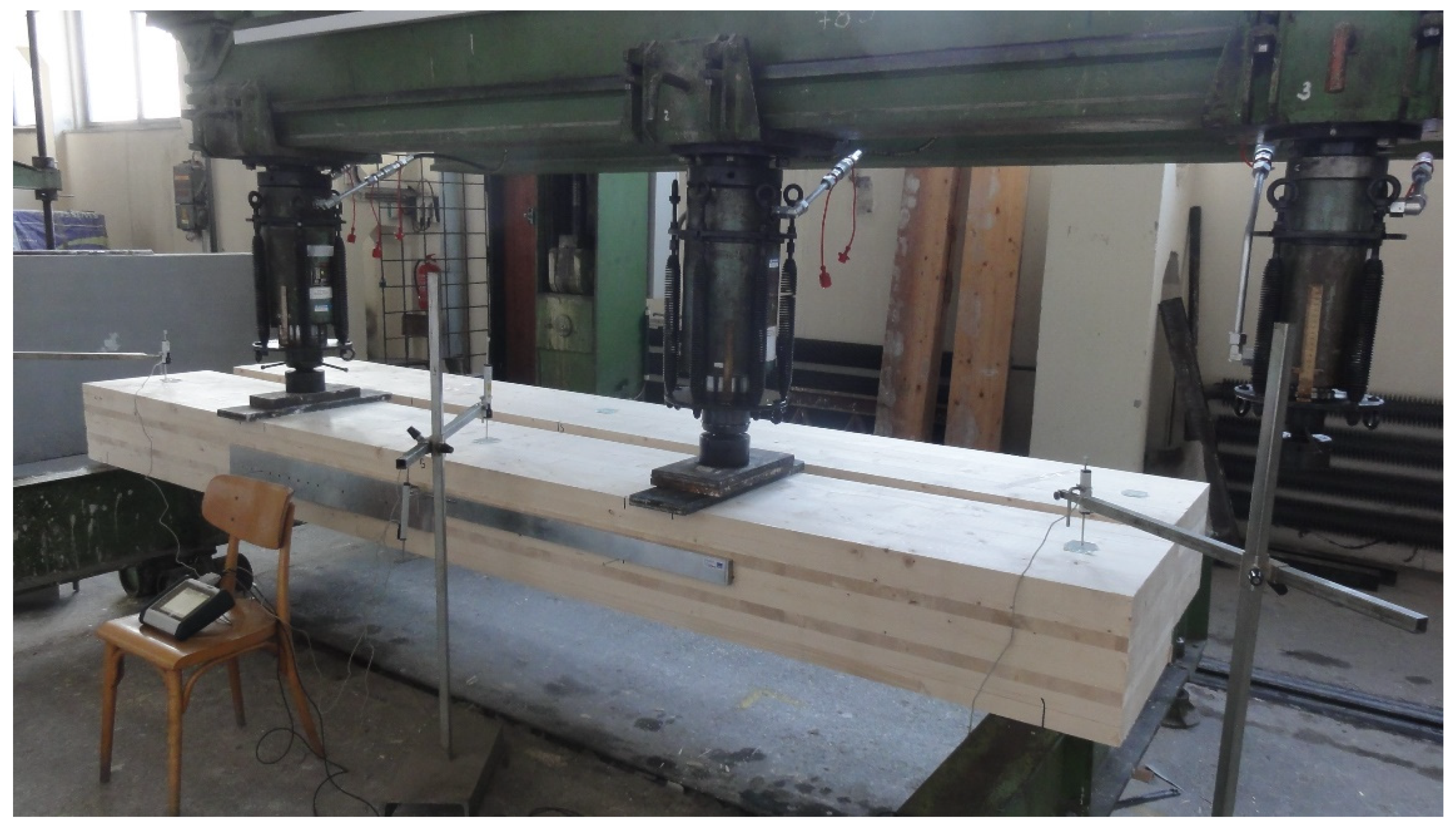
The CLT panels were supported and loaded as in the four-point bending test given in [
41] (see
Figure 5). The panels were supported on two steel I-beams with no roller support. The load speed was constant (10 mm/min) up to the maximum applied load according to recommendations of the relevant standard [
41]. The displacements of the specimens were measured by using linear variable differential transformers (LVDTs). Two LVDTs were located at the mid-span (one on the top side, one on the bottom side) for measuring the maximum deflection. The final deformation
w was considered as the mean of the measurements on both sides at the neutral axis. Two other LVDTs were located above the support for the correction due to embedment. This correction of the maximum deflection is carried out for the correct determination of bending stiffness. All these displacements were used for the determination of the global modulus of elasticity. The displacements for the determination of the local modulus of elasticity were measured over a central gauge length of 5x thickness of the CLT panel [
46].
The measured deflection values corresponding to the individual loading levels were used to create load–deformation curves. The part of the curves between 10% and 40% of the estimated maximum load-carrying capacity was applied for regression analysis, with a minimum required correlation coefficient of 0.99 [
41,
42]. This condition was met for all the tested specimens.
2.2. Local Modulus of Elasticity in Bending
For the local modulus of elasticity in bending, the deflection is measured between the load points over the central gauge length
l1 = 5h and is determined by the formula [
41]:
where
F2 − F1 is the increment of load (N) on the regression line with a correlation coefficient of 0.99 and better;
w2 − w1 is the increment of deformation (mm) corresponding to F2 − F1;
a is the distance between the support point and the force point (mm);
l1 is the distance between the fixed points over the central gauge length (mm);
I is the moment of inertia of the cross-section (mm4).
2.3. Global Modulus of Elasticity in Bending
For the global modulus of elasticity, the deflection is measured at the mid-span and is determined by the formula [
41]:
where
F2 − F1 is the increment of load (N) on the regression line with a correlation coefficient of 0.99 and better;
w2 − w1 is the increment of deformation (mm) corresponding to F2 − F1;
G is the shear modulus (value 690 MPa for C24 strength class);
l is the span (mm);
b is the panel width (mm);
h is the panel height (mm).
2.4. Bending Stiffness of CLT Panels
The calculation of the bending stiffness (see Equation (3)) of CLT is based on the theory of linear elasticity. Only layers in the longitudinal direction (i.e., loading direction) are considered in the calculation. On the contrary, the stiffness of layers in the transverse direction is neglected. Effective bending stiffness can be obtained according to the equations from Eurocode 5 (Annex B) [
32]. The standard describes the calculation of the bending stiffness of mechanically connected beams (so-called Gamma method). Steiner’s theorem is used in the calculation, and a certain degree of compliance between the glued layers is considered (coefficients of shear compliance
γ).
where
Ei are the moduli of elasticity of the individual layers (determined according [
45]) (N/mm
2);
Ii are the moments of inertia of the individual layers (mm4);
Ai are the cross-sectional areas of the individual layers (mm2);
ai are the distances between the centers of mass of the individual layers and the center of mass of the panel (mm);
hi are the heights of the individual layers (mm).
However, the calculation of the coefficients of shear compliance in the Gamma method must be adjusted for glued beams according to the formulas given in [
34].
2.5. Analytical Calculation of the Maximum Deflection
The maximum deflection at the mid-span was calculated for comparing different approaches. The load force value was
F = 2 × 20 kN = 40 kN, which corresponds to approximately 40% of the estimated maximum load-carrying capacity of the panel, where the linear elastic behavior of timber can still be considered. Using the average effective bending stiffness
EIef,g (global MOE) obtained on the basis of the test results, the maximum deflection according to the linear equation is (the variables are explained above in
Section 2.2 and
Section 2.3):
2.6. Numerical Model of the CLT 140-3 in FEM Software SCIA Engineer
The CLT 140-3 panels were used for the stiffness and deformation analysis using numerical methods. The CLT panel was modeled in FEM software SCIA Engineer 18.1 using plate elements with orthotropy. The orthotropic material was defined by several physical constants. These values were calculated according to the SCIA Engineer online manual [
47].
Table 1 and
Table 2 show the parameters of orthotropy for the outer layers and inner layer of the CLT 140-3 (for clarification and way of determination of stiffness parameters given in
Table 1 and
Table 2, see [
47]).
The panels were modeled using timber of C24 strength class. This was determined on the basis of a standard for sorting by strength [
45]. The load was applied to two areas of the top layer (as a free surface load), which corresponded to the contact surfaces between the steel plates and the CLT panel. The individual layers were connected by rigid arms. The translational rigidity in the longitudinal direction was defined at the end of each rigid arm. This represented the shear compliance between the layers. The translational rigidity was determined on the basis of the calculated shear compliance coefficient for glued connections and the distance between the rigid arms according to:
where
Ei are the moduli of elasticity of the individual layers (determined according [
45]) (N/mm
2);
Ai are the cross-sectional areas of the individual layers (mm2);
s is the distance between rigid arms (mm);
l is the span (mm);
γi are the coefficients of shear compliance (determined according Equations (4)–(6)) (-);
Ki is the translational rigidity (N/mm).
For the numerical model (see
Figure 6), the value of the translational rigidity in the connection of one rigid arm,
K = 253,000 N/mm, was used.
The other two types of panels (CLT 160-5 and CLT 240-7-2) were not modeled using finite element analysis. However, it can be assumed that similar procedures and similar methods could be used.
2.7. Numerical Model of CLT 140-3 in FEM Software ANSYS
2.7.1. Orthotropic Material Model
Timber is an anisotropic material. It is correct to simplify the orthotropic behavior using cylindrical orthotropy (with considering the curvature of annular rings) or rectangular orthotropy (without considering) when we carry out a numerical analysis [
48]. The influences of local timber defects (knots and cracks), annular rings, differences between spring and summer timber, etc., were neglected in the numerical model for this paper [
49].
There are three mutually perpendicular directions for timber (see
Figure 7) according to [
50]. They are defined by the longitudinal direction
L (the grain direction), the tangential direction
T (perpendicular to the grain and tangential to the annular rings) and the radial direction
R (perpendicular to the grain and perpendicular to the annular rings).
The timber material model is defined by nine elastic constants in the system of rectangular L, T and R coordinates as: the modulus of elasticity in the longitudinal direction EL, the modulus of elasticity in the tangential direction ET, the modulus of elasticity in the radial direction ER, shear moduli GLT, GLR and GTR in the planes LT, LR and TR, and the Poisson’s ratios νLT, νLR and νTR in the planes LT, LR and TR.
The inverse relation of the Hook’s law for a rectangular orthotropic material can be written:
where
ε is the elastic strain tensor (-);
C is the elastic compliance matrix (mm2/N) (see Equation (10));
Σ is the stress tensor (N/mm2).
The elastic material constants of rectangular orthotropy for spruce were determined based on the standards [
32,
45] (Young’s moduli and shear moduli for C24 strength class) or were taken from the Wood Handbook [
13] (Poisson ratios) and are shown in
Table 3.
Material models of polyurethane adhesive (connection of timber elements) and structural steel (supporting beams, load distribution plates) were taken from the ANSYS software database. Polyurethane adhesive: ρ = 1160 kg/m3; E = 3780 MPa; ν = 0.35. Structural steel: ρ = 7850 kg/m3; E = 200,000 MPa (this value is used by the software unlike the design standard value of E = 210,000 MPa); ν = 0.3.
2.7.2. Numerical Model
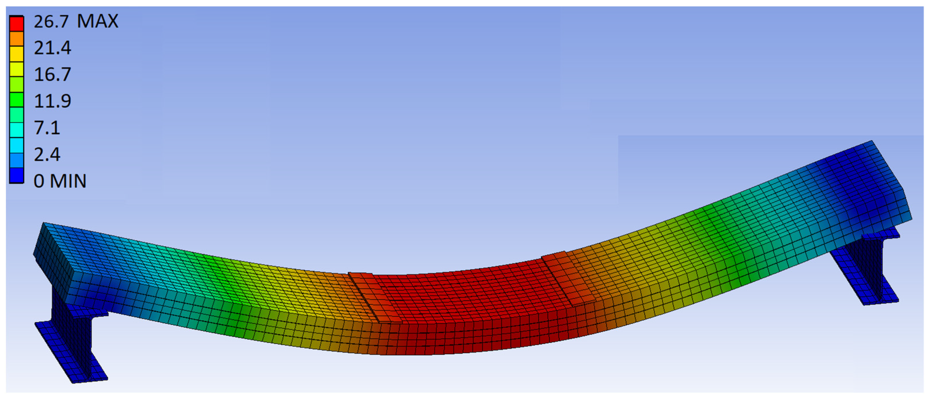
The numerical model in ANSYS Workbench 18.0 (see
Figure 8) was used to simulate the real arrangement of the experimental test. The outer load-carrying layers of the CLT panel were modeled as individual planks, while the middle non-load-carrying layer was simplistically modeled as one continuous layer. A thin layer of epoxy resin was added between the individual planks in the outer load-carrying layers and also between the outer load-carrying layers and the middle non-load-carrying layer. This layer represented the bonding together. The CLT panel was supported by two steel I-beams (flange width of 150 mm). The load was transferred through two steel plates of width 100 mm and thickness 10 mm.
The contacts between the timber elements and the epoxy resin were set as “bonded”. The contacts between the steel plates and the panel and between the steel I-beams and the panel were set as “frictional”. The coefficient of friction between steel and timber was f = 0.55.
The numerical model consisted of 3D finite elements. The finite element mesh was automatically generated by the software. The size of the finite element mesh was set from 30 to 40 mm. A finer mesh no longer led to more accurate results.
4. Discussion
The average values of the global deflection obtained from the laboratory tests, analytical calculations and numerical models in SCIA Engineer and ANSYS Workbench show comparable values (see the comparison in
Table 8).
Figure 12 shows the comparison of the deformation curves obtained from the laboratory tests for all tested specimens, analytical calculation and numerical methods. It is obvious that the real curves show a good agreement with the other methods.
The experiments confirmed the linear behavior of the material at load values that do not exceed 40% of the maximum load capacity (corresponds to the serviceability limit state). The deformation behavior of real CLT panels is even almost linear until failure.
The maximum deflection based on the numerical analysis in SCIA Engineer is 7.5% higher than the calculation according to the analytical equation using the average bending stiffness based on the test data. It is also 8.8% higher than the average measured deflection of the tested specimens. The maximum based on the numerical model in ANSYS Workbench is 5.1% higher than the calculation according to the analytical equation using the average bending stiffness based on the test data. It is also 6.4% higher than the average measured deflection of the tested specimens.
It is obvious from the numerical analysis results that quite similar results can be obtained by using completely different approaches in FEM analysis. In this case, a less computationally intensive, time-saving and more practical shell-beam numerical model in SCIA Engineer can approach the more complex and sophisticated numerical model in ANSYS Workbench (3D solid finite elements) with sufficient accuracy. Both numerical models also show a tolerably good agreement with the experiments and the analytical calculation. Selected methods and approaches to numerical modeling can be applied to these structural elements.
It can be seen from
Figure 12 that there is no significant decrease in stiffness even to a load corresponding to 100% of the estimated maximum. This allows the application of the theory of linear elasticity to high limits of load, almost to the limits of failure, with sufficient accuracy. These results justify the use of the simple analytical method to calculate the effective bending stiffness of structural elements from cross-laminated timber in construction practice. It can be stated that the analytical calculation according to Eurocode 5 [
32] is suitable and sufficiently accurate for this type of CLT panel.
Despite this positive fact, the panels no longer show a high ductility and soon break by transverse tension perpendicular to the grain or by rolling shear in the intermediate layer (see
Figure 13 and
Figure 14). This was soon followed by the failure of longitudinal layers by tension parallel to the grain on the bottom side at the mid-span. This failure is brittle without a plastic branch, which generally indicates the ductility of the element [
51,
52]. Specimen 1 reaches the highest real stiffness, and specimen 3 reaches the lowest stiffness. Otherwise, the deformation curves are comparable without significant deviations, which is probably due to the high quality of the used timber, which was properly graded. The individual lamellas for the production of CLT panels are carefully selected to contain as few natural imperfections and defects as possible.
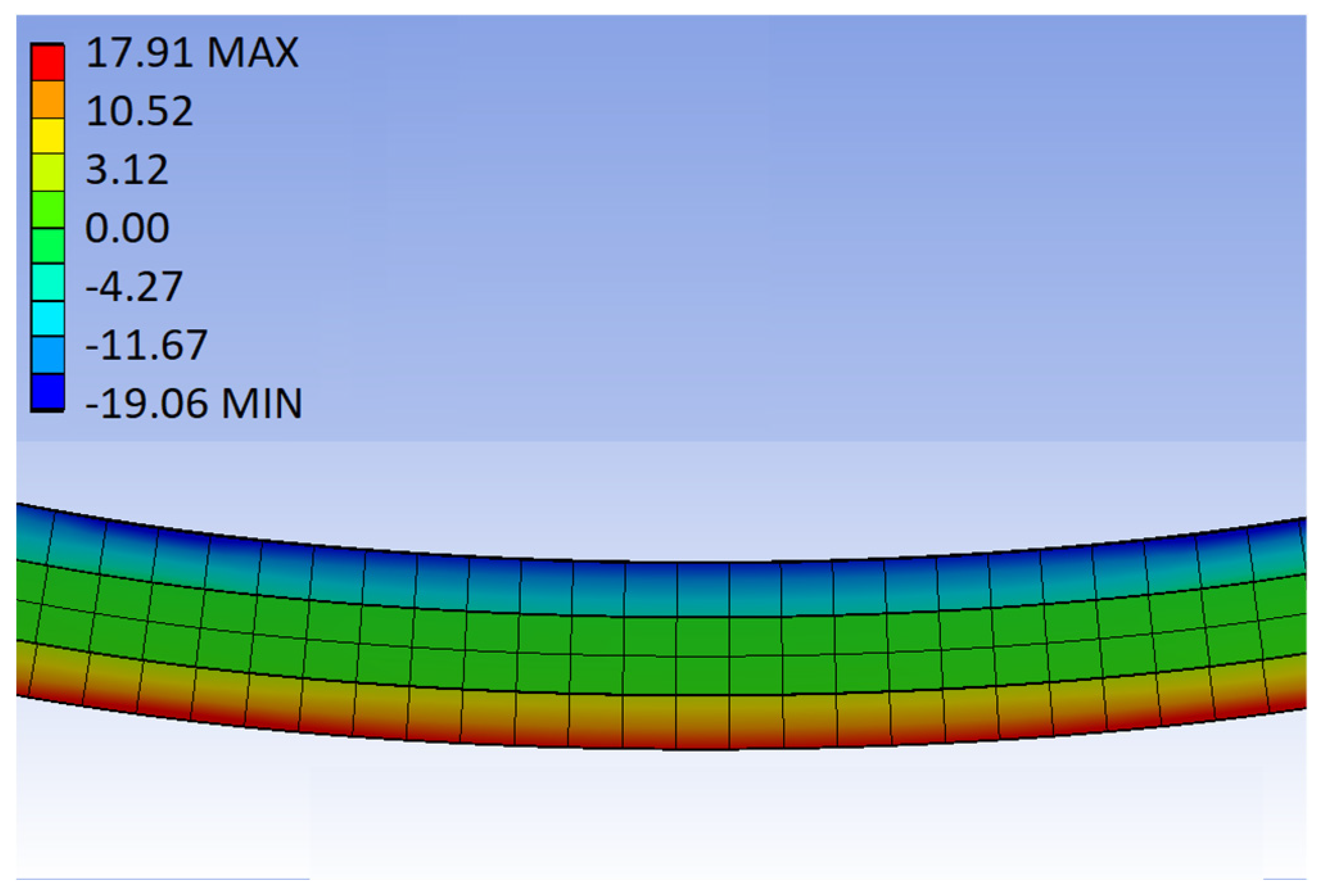
Figure 11 shows the longitudinal normal stress contour, which corresponds to the stiffness of the individual layers in the longitudinal direction. The middle transverse layer distributes load negligibly compared to the longitudinal layers, which is caused by the orthotropic behavior of the material, i.e.,
ET << EL.
5. Conclusions
Experimental testing is the most appropriate way to verify the deformation behavior of timber structures, including cross-laminated timber. Therefore, static tests on specific CLT panels made of Nordic spruce were performed. There is not enough relevant information in the scientific discourse about the selected panels, which was the reason for a more detailed analysis of the behavior of bending.
The paper shows the determination of the bending stiffnesses of CLT panels based on test data. The results on three-layered CLT panels show a good agreement in the bending behavior between the laboratory tests, the analytical calculation according to the standard. It is obvious that simple analytical calculation is suitable for determination of the bending stiffnesses.
The paper also describes how to model CLT panels using the orthotropic material model in FEM software SCIA Engineer and ANSYS Workbench. Both numerical models show a good agreement with the experiments and the analytical calculation. Beam-shell numerical analysis with orthotropy in SCIA proved to be appropriate for CLT panels. This approach has thus proven to be effective due to its simplicity.
On the basis of these results, the deflections at the mid-span were compared as part of the deformation analysis. The small differences in the maximum deflections are due to the fact that it is not possible to accurately determine the timber strength class of the real specimens and to implement their real material inhomogeneities into the numerical model.
The study presented in this paper has certain limitations. Three different types of CLT were experimentally tested. However, only one type of tested CLT panels was used for the comparison with the results of theoretical and numerical analyses within the deformation analysis (three layers 40-60-40 mm). Furthermore, the CLT panels were made only of one species of timber (spruce, C24 strength class). The number of test specimens was limited, which could affect the statistical evaluation. The tested CLT panels were subjected only to monotonic quasi-static loading.
CLT panels are used for the construction of multi-story buildings (residential buildings, warehouses) due to their excellent strength and stiffness characteristics. CLT panels of different types and geometries are used in construction practice, which are subjected not only to bending. It is possible to perform experimental testing and its numerical verification on other types of CLT panels. These exterior structures are also often predominantly loaded by wind (alternating dynamic load). Based on this fact, future research in this area should incorporate experiments with cyclic and dynamic tests. The numerical analysis could be carried out for other types of CLT panels as well. Both approaches of numerical modeling could be universal and applicable to other types of CLT panels.


