
Development of a Low-pH Concrete Intended for Deep Geological Repository for Radioactive Waste
Abstract
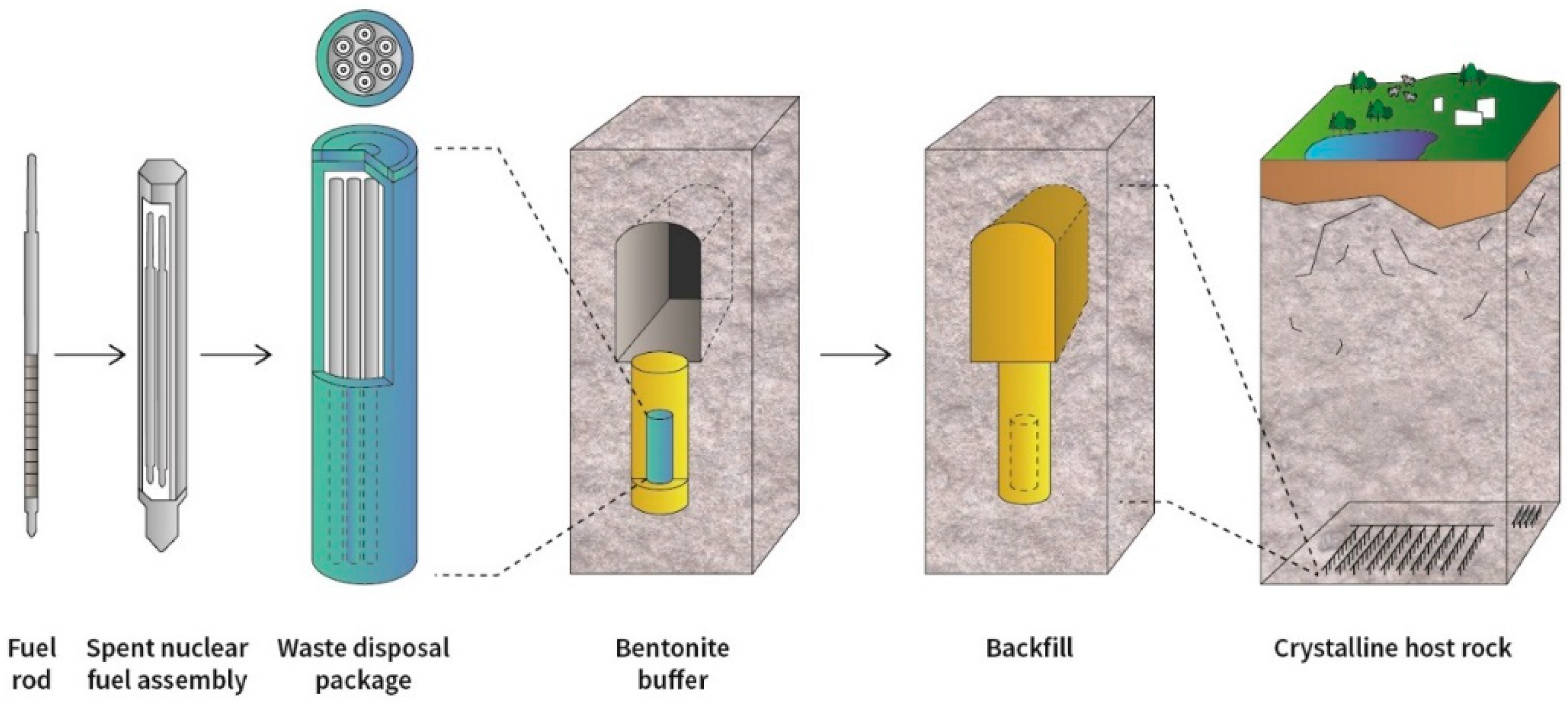
:1. Introduction
2. Materials and Methods
2.1. Methods for Testing the Measured Quantities
2.1.1. Fresh Mixture
2.1.2. Concrete
3. Results
3.1. Fresh Mixture Properties
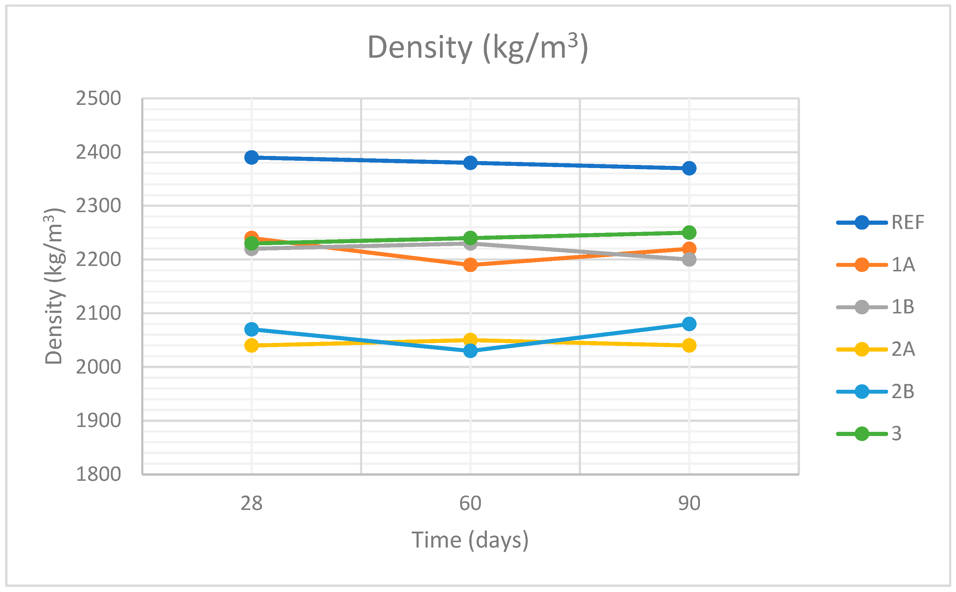
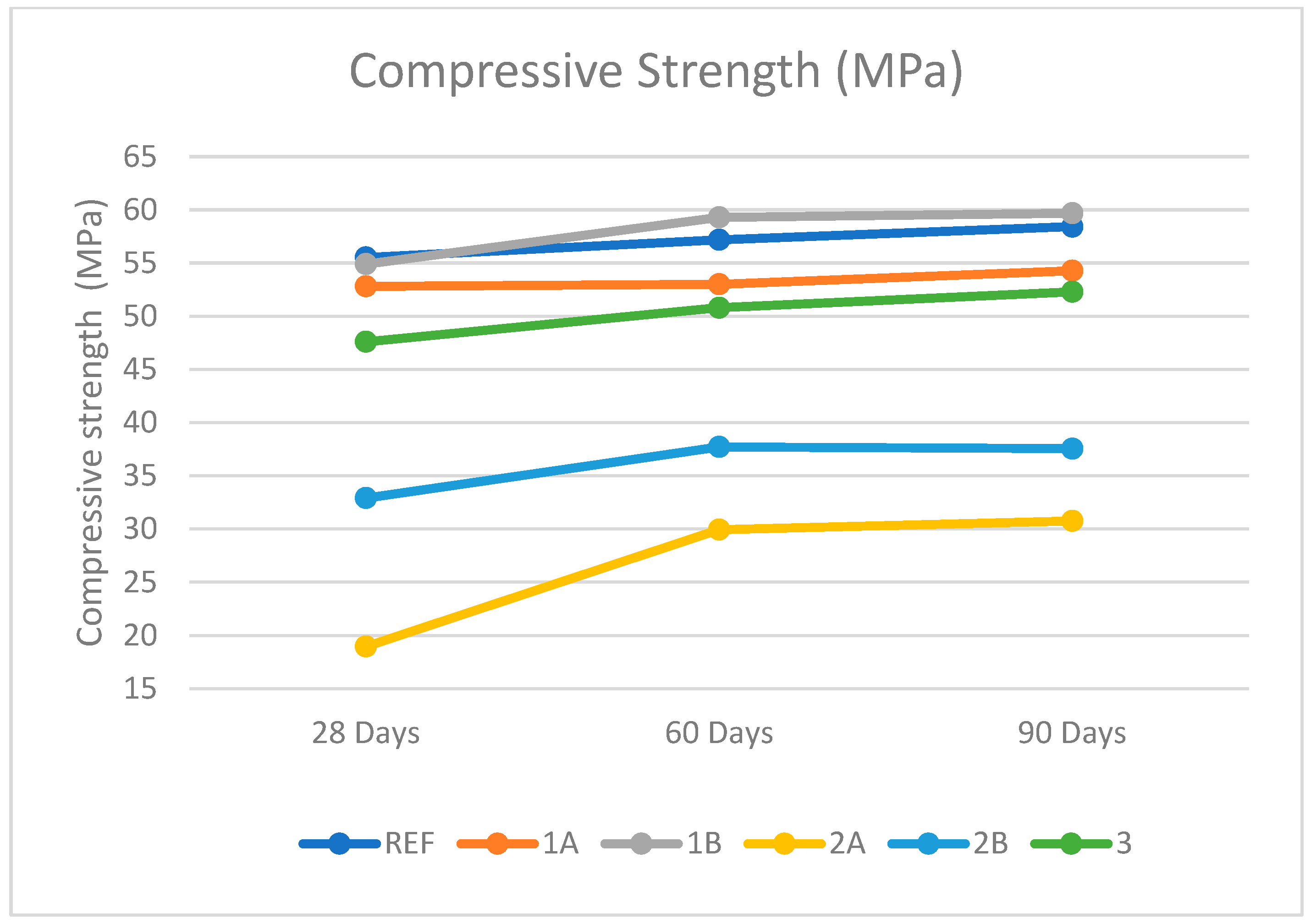
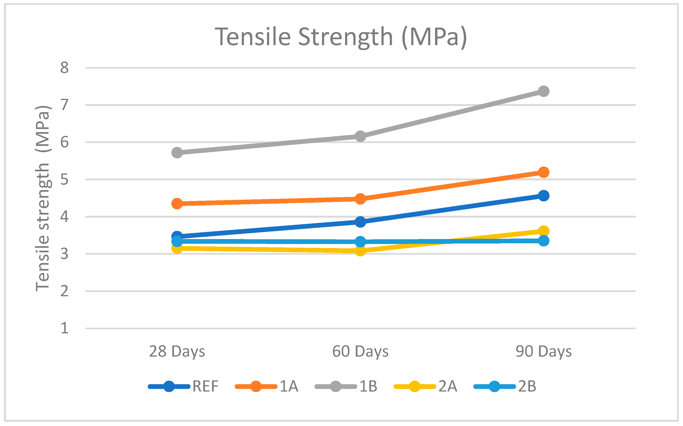
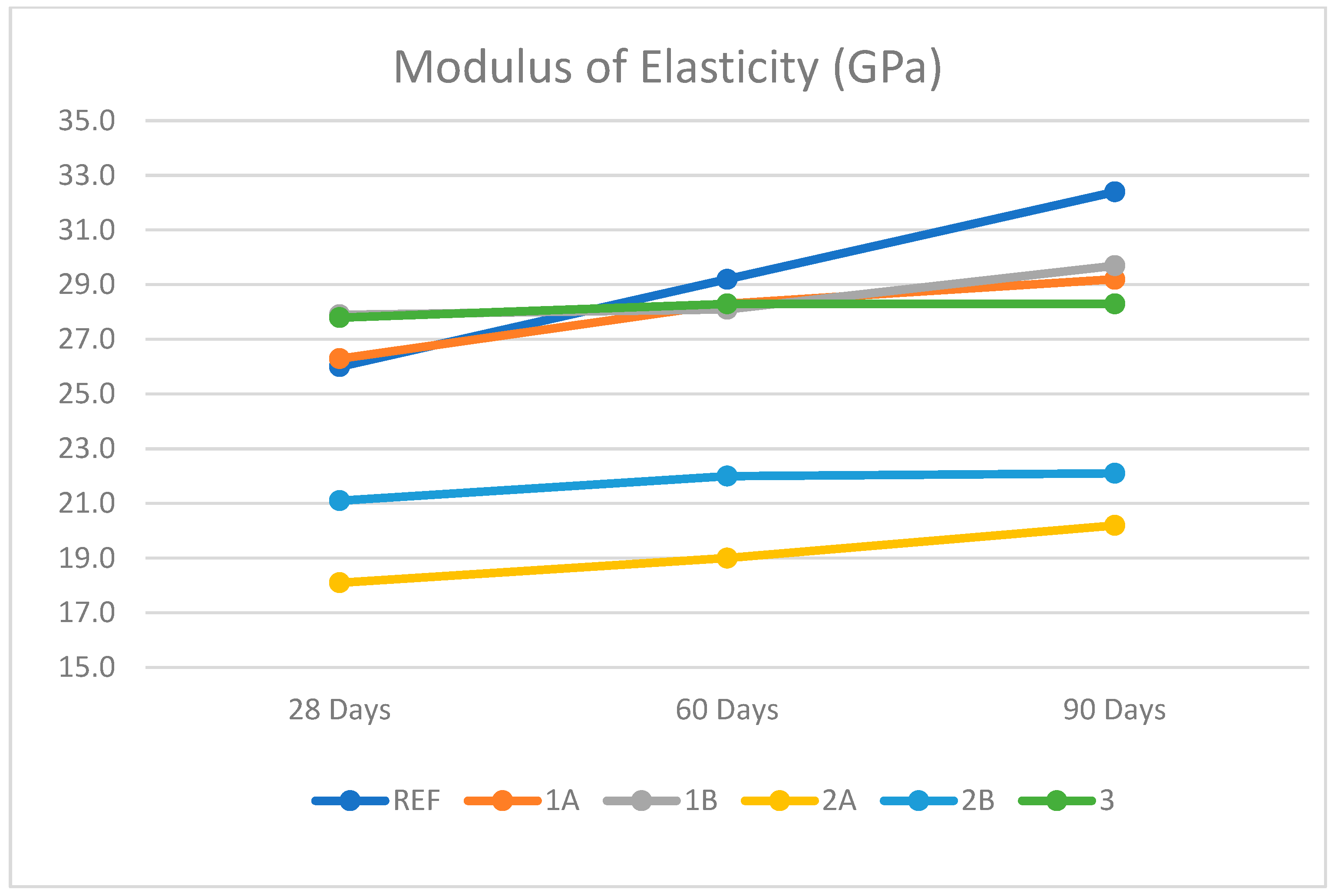
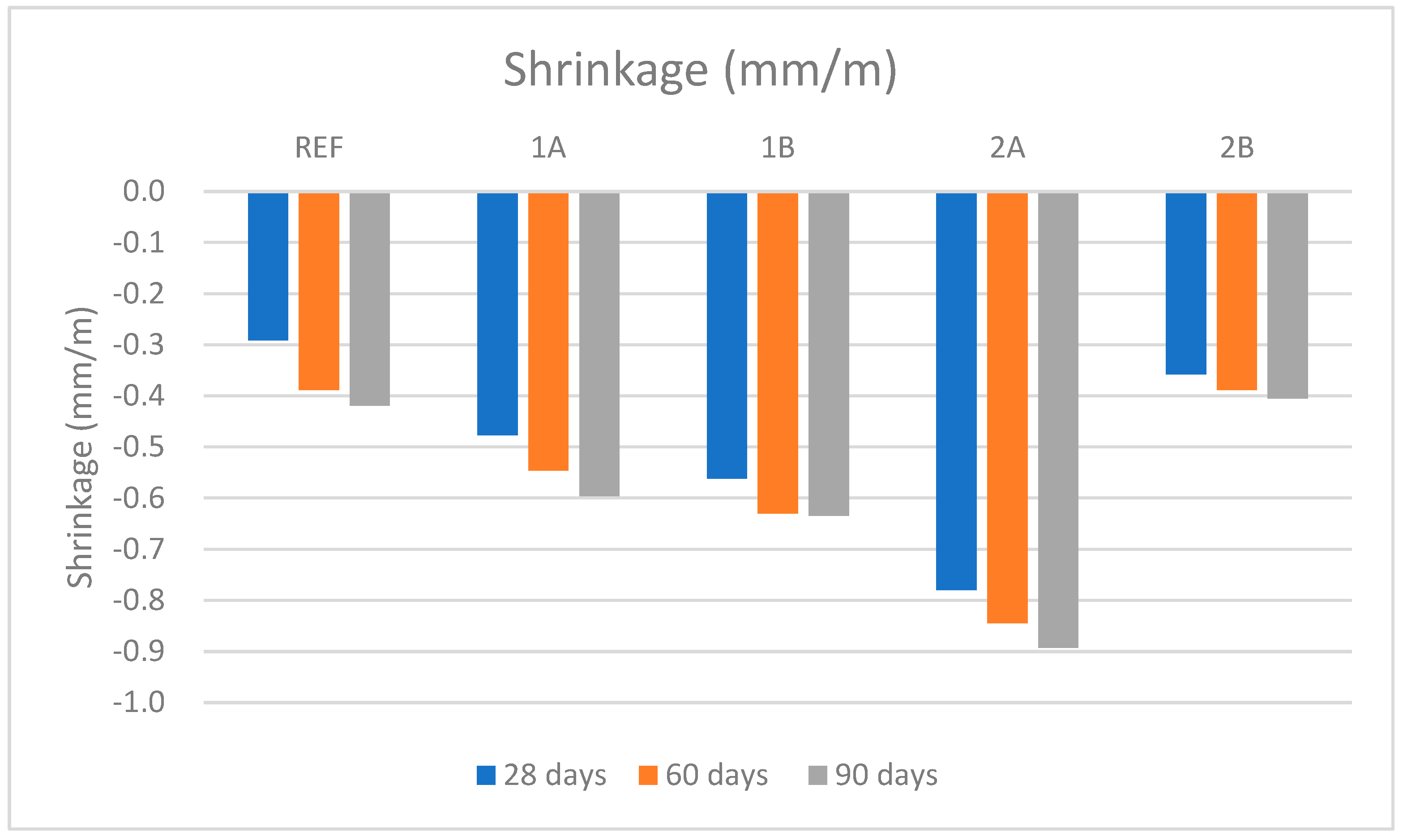
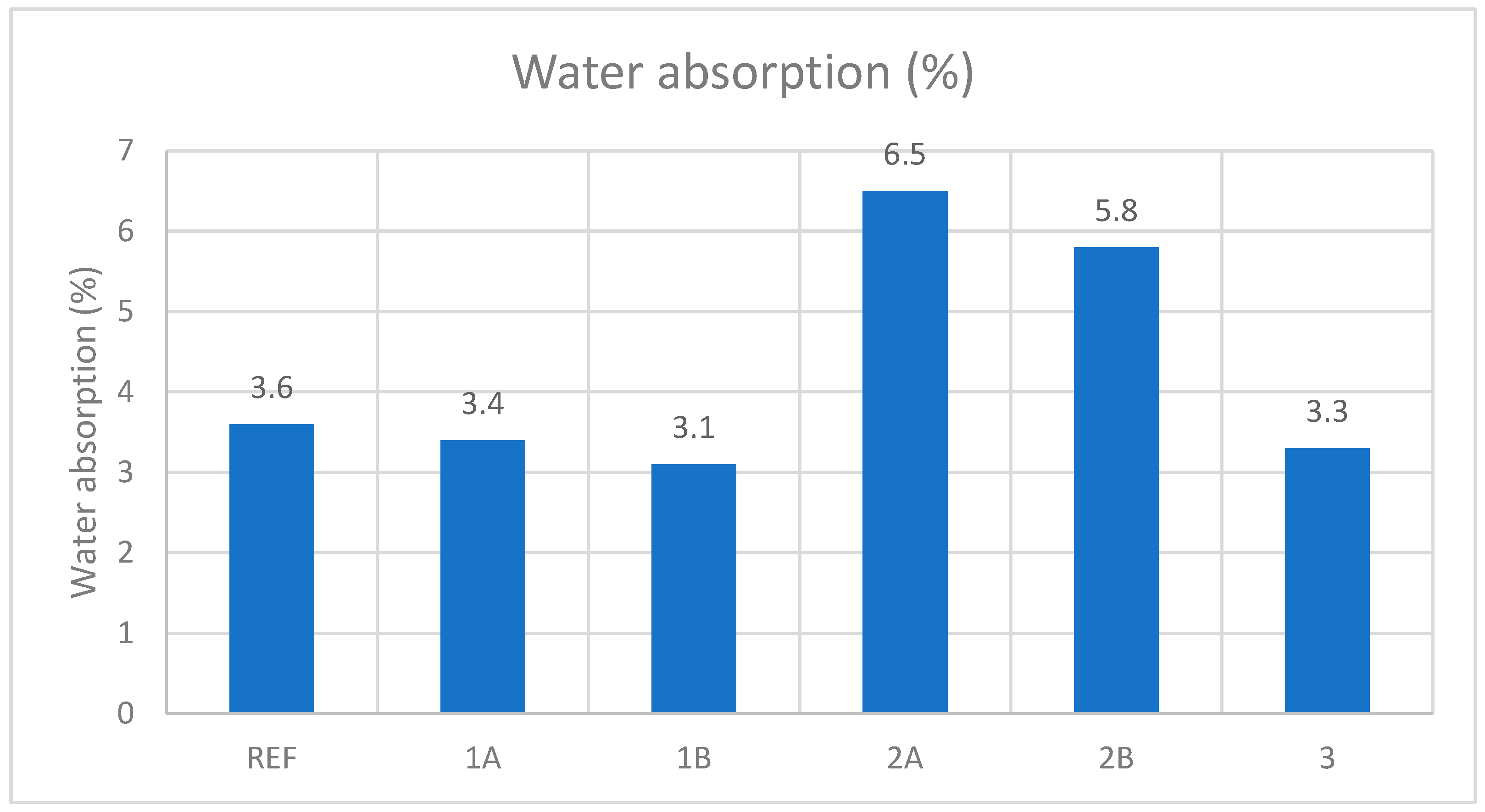
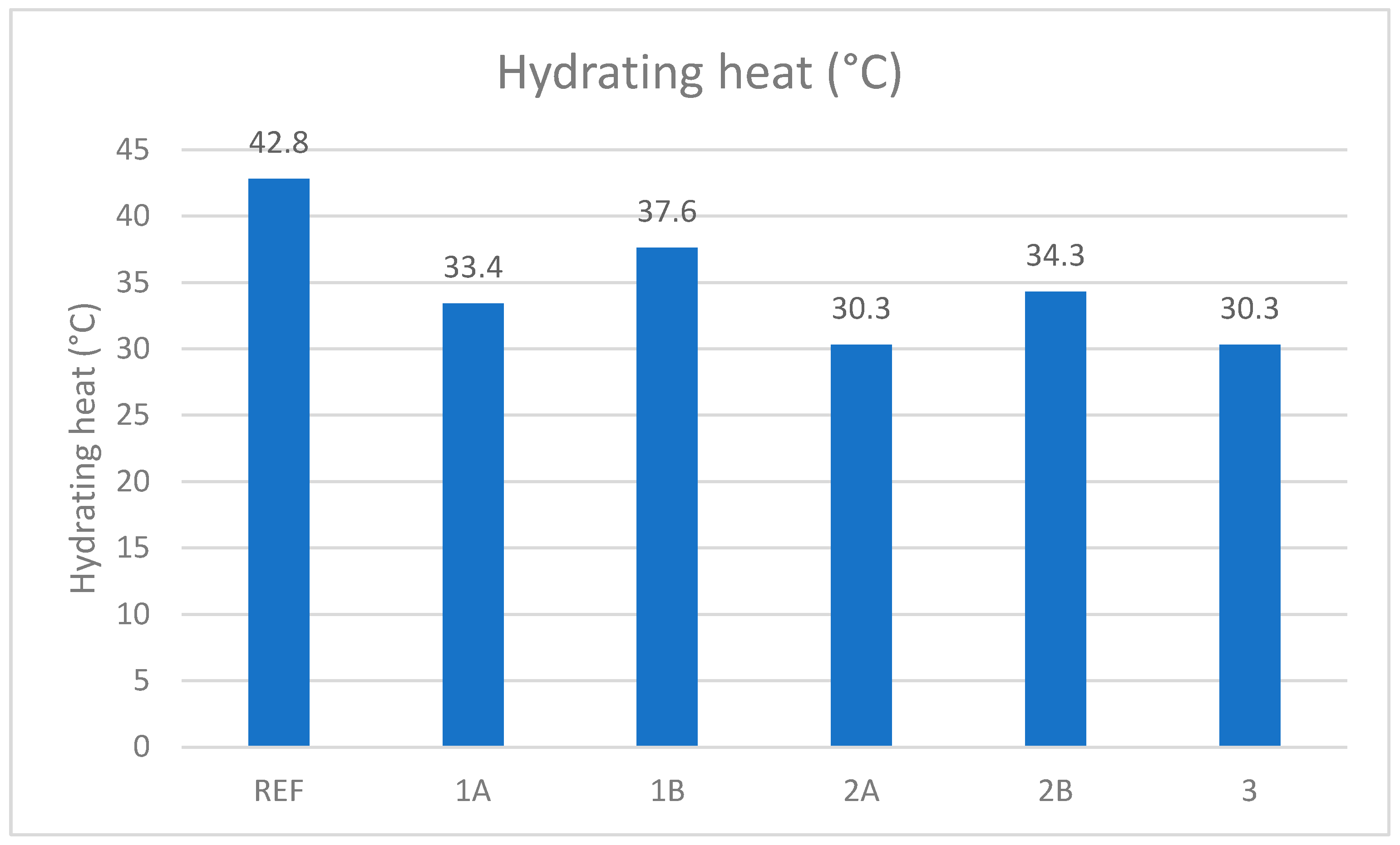
3.2. Concrete Properties
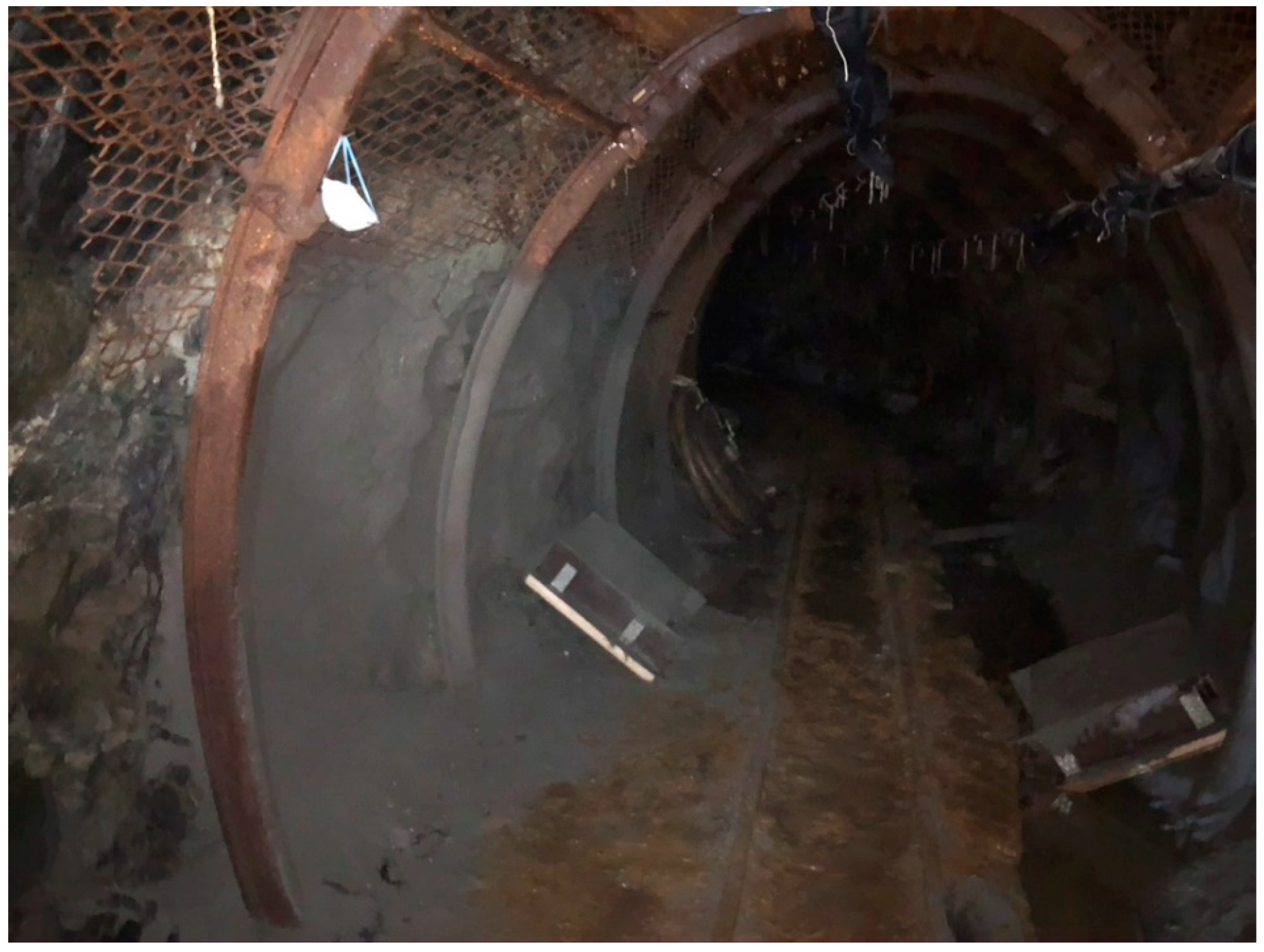
3.3. Shotcrete
4. Discussion
5. Conclusions
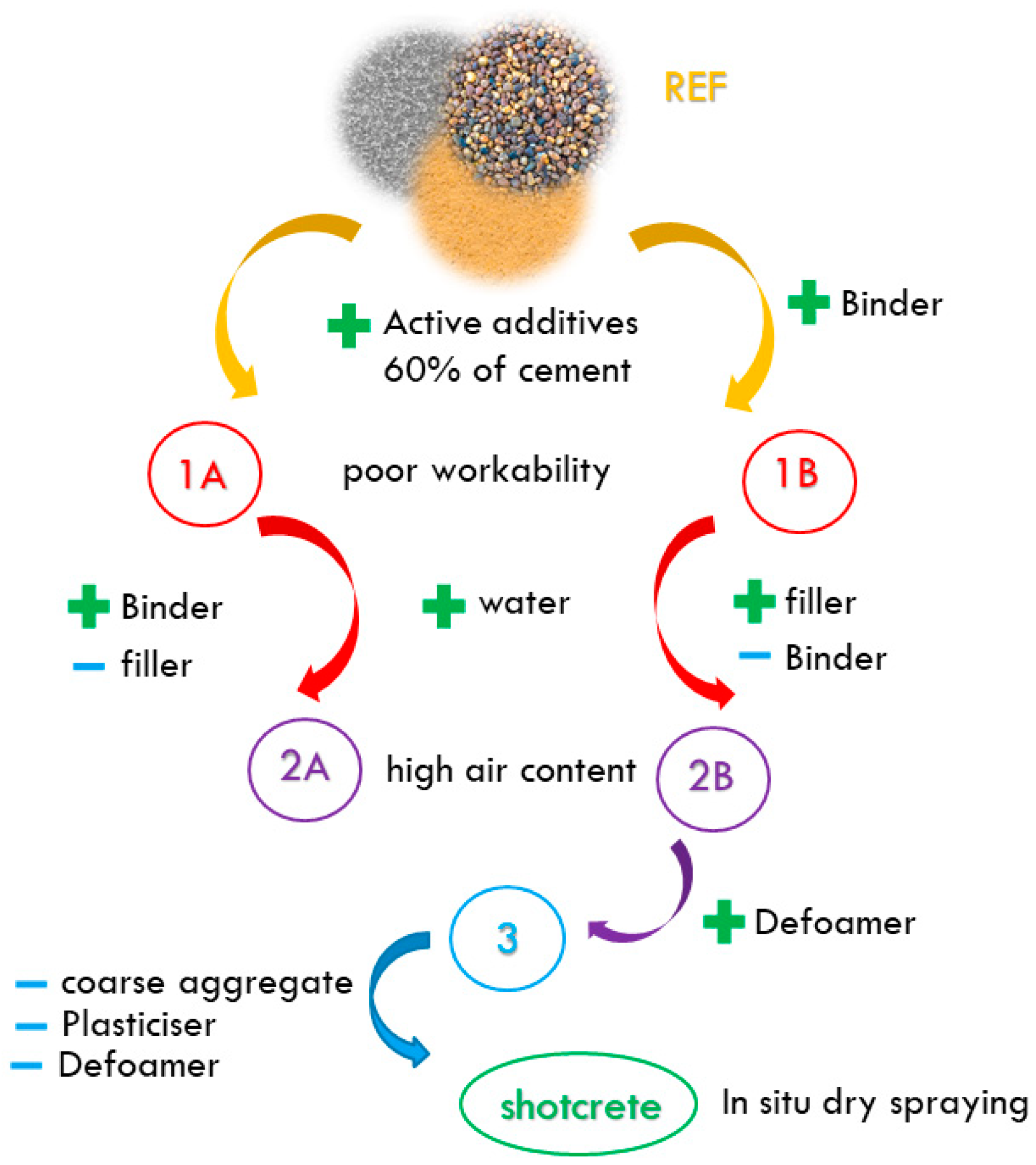
- A controlling factor for designing an LPC is the characteristics of the fresh mixture. The processability of the mixture (with regard to its further use) plays a significant role in deciding on the type and quantity of additives.
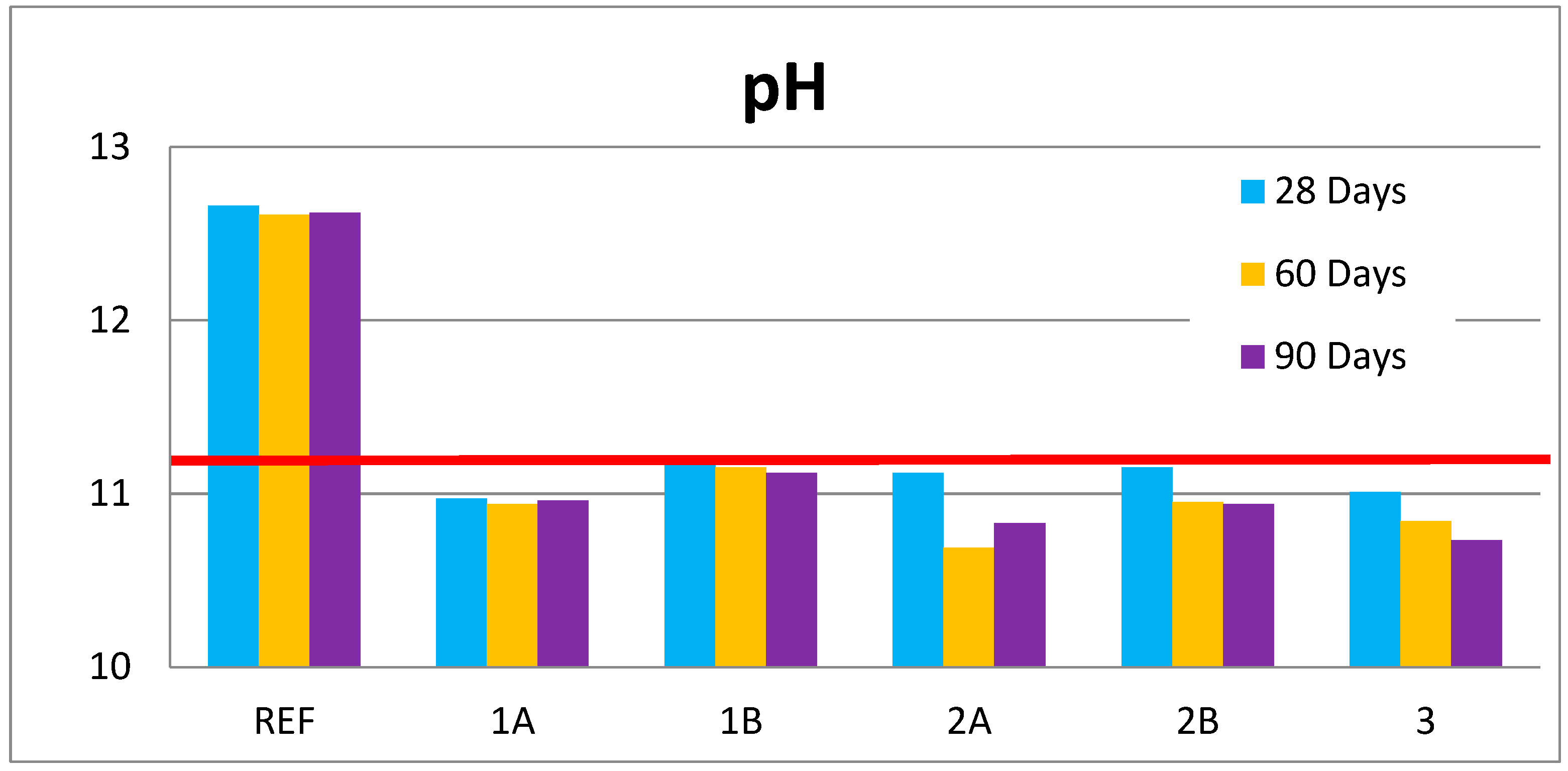
- The results of mechanical tests show a similar value as normal concrete (CEM I 42.5) and at the same time meet the required value of pH for low-pH concretes (in this case, a pH value of around 11 in the long term).
- The final designed recipe has a different binder composition (CEM I 40%, microsilica 51%, and slag 9%) than was presented in previous studies in previous years. This is due to the use of local raw materials. It is assumed that one cannot simply adopt the formula of LPC without checking its properties.
- Due to application of low-pH shotcrete, it was proved that the designed mixture can be modified for the technology of sprayed concrete, even for use under the ground.
Author Contributions
Funding
Institutional Review Board Statement
Informed Consent Statement
Data Availability Statement
Conflicts of Interest
References
- El-Showk, S. Final resting place. Science 2022, 375, 806–810. [Google Scholar] [CrossRef]
- Keusen, H.R.; Ganguin, J.; Schuler, P.; Buletti, M. Grimsel Test Site: Geology; Nationale Genossenschaft fuer die Lagerung Radioaktiver Abfaelle: Wettingen, Switzerland, 1989; pp. 1–167. [Google Scholar]
- Tournassat, C.; Steefel, C.I.; Bourg, I.C.; Bergaya, F. Natural and Engineered Clay Barriers. In Developments in Clay Science; Elsevier: Amsterdam, The Netherlands, 2015; pp. 1–4. [Google Scholar]
- Stastka, J.; Hanusova, I.; Hausmannova, L.; Kucerova, M. In-situ testing of Czech bentonite for radioactive waste disposal in Mock-up Josef experiment. Ann. Nucl. Energy 2022, 172, 109059. [Google Scholar] [CrossRef]
- SURAO. Available online: https://www.surao.cz/ke-stazeni/ (accessed on 16 June 2022).
- Špinka, O.; Grunwald, L.; Zahradník, O.; Veverka, A.; Fiedler, F.; Nohejl, J. Siting Study—Březový Potok; Final report 139/2017; SÚRAO: Prague, Czech Republic, 2018. [Google Scholar]
- Kotnour, P. Výzkum a Vývoj Ukládacího Obalového Souboru Pro Hlubinné Ukládání Vyhořelého Jaderného Paliva Do Stádia Realizace Vzorku 3. Etapa; Technical report; SÚRAO: Prague, Czech Republic, 2017. [Google Scholar]
- Smutek, J.; Hausmannova, L.; Svoboda, J. The gas permeability, breakthrough behaviour and re-sealing ability of Czech Ca-Mg bentonite. Geol. Soc. Spec. Publ. 2017, 443, 333–348. [Google Scholar] [CrossRef]
- Hausmannová, L.; Hanusová, I.; Dohnálková, M. Summary of the Research of Czech Bentonites for Use in the Deep Geological Repository—Up to 2018; Technical report 309/2018/ENG; SÚRAO: Prague, Czech Republic, 2018. [Google Scholar]
- Malmgren, L.; Nordlund, E.; Rolund, S. Adhesion strength and shrinkage of shotcrete. Tunn. Undergr. Space Technol. 2005, 20, 33–48. [Google Scholar] [CrossRef]
- Collepardi, M. The New Concrete; Tintoretto: Los Angeles, CA, USA, 2006; pp. 1–241. [Google Scholar]
- Svoboda, J.; Mašín, D.; Najser, J.; Vašíček, R.; Hanusová, I.; Hausmannová, L. BCV bentonite hydromechanical behaviour and modelling. Acta Geotech. 2022, 297, 1–19. [Google Scholar] [CrossRef]
- Savage, D. An Assessment of the Impact of the Long Term Evolution of Engineered Structures on the Safety Relevant Functions of the Bentonite Buffer in a HLW Repository; National Cooperative for the Disposal of Radioactive Waste: Wettingen, Switzerland, 2014. [Google Scholar]
- Gaboreau, S.; Pret, D.; Montouillout, V.; Henocq, P. Quantitative mineralogical mapping of hydrated low pH concrete. Cem. Concr. Compos. 2017, 83, 360–373. [Google Scholar] [CrossRef]
- Lerouge, C.; Gaboreau, S.; Grangeon, S.; Claret, F.; Warmont, F.; Jenni, A.; Cloet, V.; Mäder, U. In situ interactions between Opalinus Clay and Low Alkali Concrete. Phys. Chem. Earth Parts A/B/C 2017, 99, 3–21. [Google Scholar] [CrossRef]
- Vehmas, T.; Holt, E. WP1 Experimental Studies—State of the Art Literature—Review; CEBAMA, European Union: Imperatriz, Brazil, 2016; pp. 1–235. [Google Scholar]
- Mohammed, M.H.; Pusch, R.; Knutsson, S.; Warr, L.N. Hydrothermal alteration of clay and low pH concrete applicable to deep borehole disposal of high-level radioactive waste—A pilot study. Constr. Build. Mater. 2016, 104, 1–8. [Google Scholar] [CrossRef]
- García Calvo, J.L.; Hidalgo, A.; Alonso, C.; Fernández Luco, L. Development of low-pH cementitious materials for HLRW repositories. Resistance against ground waters aggression. Cem. Concr. Res. 2010, 40, 1290–1297. [Google Scholar] [CrossRef]
- Leivo, M.; Holt, E.; Vehmas, T. Betonirakenteet Ydinpolttoaineen Loppusijoituksessa; Teknologian Tutkimuskeskus VTT: Espoo, Finland, 2013; pp. 1–21. [Google Scholar]
- Vogt, C.; Lagerblad, B.; Wallin, K.; Baldy, F.; Jonasson, J.E. Low pH Self-Compacting Concrete for Deposition Tunnel Plugs; Report R-09-07; Swedish Nuclear Fuel and Waste Management: Stockholm, Sweden, 2019; pp. 1–78. [Google Scholar]
- Zuo, J.; Zhan, J.; Dong, B.; Luo, C.; Liu, Q.; Chen, D. Preparation of metal hydroxide microcapsules and the effect on pH value of concrete. Constr. Build. Mater. 2017, 155, 323–331. [Google Scholar] [CrossRef]
- Nishimura, T.; Raman, V. Corrosion behavior of reinforcing steel in concrete for nuclear facilities exposed in high chloride and low pH environment. J. Nucl. Mater. 2010, 397, 101–108. [Google Scholar] [CrossRef]
- El Bitouri, Y.; Buffo-Lacarrière, L.; Sellier, A.; Bourbon, X. Modelling of chemo-mechanical behaviour of low pH concretes. Cem. Concr. Res. 2016, 81, 70–80. [Google Scholar] [CrossRef] [Green Version]
- Prošek, Z.; Nežerka, V.; Hlůžek, R.; Trejbal, J.; Tesárek, P.; Karra’a, G. Role of lime, fly ash, and slag in cement pastes containing recycled concrete fines. Constr. Build. Mater. 2019, 201, 702–714. [Google Scholar] [CrossRef]
- Pernicova, R.; Pavlikova, M.; Cerny, R. Effect of metakaolin on chloride binding in lime-based composites. In Computational Methods and Experimental Measurements XIII; WIT Press: Boston, MA, USA, 2007; Volume 46, p. 357. [Google Scholar]
- Hoškova, S.; Tichá, P.; Demo, P. Determination of Ca2+ ions at early stage of hydrating cement paste fines. Ceram.-Silik. 2009, 53, 76–80. [Google Scholar]
- Cong, X.; Kirkpatrick, J.R. 29Si MAS NMR study of the structure of calcium silicate hydrate. Adv. Cem. Based Mater. 1996, 3, 144–156. [Google Scholar] [CrossRef]
- Hong, S.Y.; Glasser, F.P. Alkali binding in cement pastes Part I. The C–S–H ph. Cem. Concr. Res. 1999, 29, 893–1903. [Google Scholar] [CrossRef]
- Dole, L.R.; Mattus, C.H. Low pH Concrete for use in the high-level waste repository: Part I overview. In R&D on Low-pH Cement for a Geological Repository; Nuclear Science Technology Division of Oak Ridge National Laboratory: Oak Ridge, TN, USA, 2007. [Google Scholar]
- Bellmann, F.; Erfurt, W.; Ludwig, H.M. Field performance of concrete exposed to sulphate and low pH conditions from natural and industrial sources. Cem. Concr. Compos. 2012, 34, 86–93. [Google Scholar] [CrossRef]
- Pernicová, R.; Čítek, D.; Dobiáš, D.; Kolísko, J.; Mandlík, T.; Hausmannová, L. Effect of Binder Components on the pH of Concrete Mixture with Low pH Intended for Deep Geological Repository for Radioactive Waste in the Czech Republic. Key Eng. Mater. 2020, 868, 15–23. [Google Scholar] [CrossRef]
- Coumes, C.D. Low pH Cements for Waste Repositories: A Review; Laboratoire d’Etude de l’Enrobage des Déchets: Marcoule, France, 2008; pp. 1–42. [Google Scholar]
- Hlaváč, J. Základy Technologie Silikátů, 2nd ed.; SNTL: Praha, Czech Republic, 1988; pp. 444–465. [Google Scholar]
- Klecka, T. Příručka Technologa—BETON, 2nd ed.; HeidelbergCement: Beroun, Czech Republic, 2005; pp. 1–292. [Google Scholar]
- Silica Fume Association. What Is Silica Fume? Available online: https://www.silicafume.org/general-silicafume.html (accessed on 4 August 2022).
- Bilim, C.; Atiş, C.D.; Tanyildizi, H.; Karahan, O. Predicting the compressive strength of ground granulated blast furnace slag concrete using artificial neural network. Adv. Eng. Softw. 2009, 40, 334–340. [Google Scholar] [CrossRef]
- MCT—Betonové Výrobky a Beton. Available online: https://www.mct.cz/ (accessed on 16 June 2022).
- ČSN EN 12350-6; Testing Fresh Concrete—Part 6: Volumetric Mass Density. European Committee for Standardization: Brussels, Belgium, 2020.
- ČSN EN 12350-7; Testing Fresh Concrete—Part 7: Air Content—Pressure Methods. European Committee for Standardization: Brussels, Belgium, 2020.
- ČSN EN 12390-7; Testing Hardened Concrete—Part 7: Density of Hardened Concrete. European Committee for Standardization: Brussels, Belgium, 2020.
- Behnood, A.; van Tittelboom, K.; de Belie, N. Methods for Measuring pH in Concrete: A review. Constr. Build. Mater. 2016, 105, 176–188. [Google Scholar] [CrossRef]
- ČSN EN 12390-3; Testing Hardened Concrete—Part 3: Compressive Strength of Test Specimens. European Committee for Standardization: Brussels, Belgium, 2020.
- ČSN EN 12390-5; Testing Hardened Concrete—Part 5: Flexural Strength of Test Specimens. European Committee for Standardization: Brussels, Belgium, 2020.
- ČSN ISO 1920-10; Testing of Concrete—Part 10: Determination of the Static Modulus of Elasticity in Compression. European Committee for Standardization: Geneva, Switzerland, 2016.
- ČSN 73 1316; Stanovení Vlhkosti, Nasákavosti a Vzlínavosti Betonu. Czechoslovak State Standard: Prague, Czech Republic, 1990.
- Dauzeres, A.; Achiedo, G.; Nied, D.; Bernard, E.; Alahrache, S.; Lothenbach, B. Magnesium perturbation in low-pH concretes placed in clayey environment—Solid characterizations and modelling. Cem. Concr. Res. 2016, 79, pp. 137–150. [Google Scholar] [CrossRef]
- Deschner, F.; Winnefeld, B.; Lothenbach, B.; Seufert, S.; Schwesig, P.; Dittrich, S.; Goetz-Neunhoeffer, F.; Neubauer, J. Hydration of Portland cement with high replacement by siliceous fly ash. Cem. Concr. Res. 2012, 42, 1389–1400. [Google Scholar] [CrossRef]
- Nuclear Decommissioning Authority. Geological Disposal: Near-Field Evolution Status Report; Report no. NDA/RWMD/033; Nuclear Decommissioning Authority: England, UK, 2010. [Google Scholar]
- Zhang, T.; Cheeseman, C.R.; Vandeperre, L.J. Development of low-pH cementitious materials for HLRW repositories Resistance against ground waters aggression. Cem. Concr. Res. 2011, 41, 439–442. [Google Scholar] [CrossRef]
- Dauzères, A.; Le Bescop, P.; Sardini, P.; Cau Dit Coumes, C. Physico-chemical investigation of clayey/cement-based materials interaction in the context of geological waste disposal: Experimental approach and results. Cem. Concr. Res. 2010, 40, 1327–1340. [Google Scholar] [CrossRef]
- Taylor, H.F.W. Cement Chemistry; Academic Press: London, UK, 1990; pp. 305–307, 374–378. [Google Scholar]
- Behnood, A.; Ziari, H. Effects of silica fume addition and water to cement ratio on the properties of high-strength concrete after exposure to high temperatures. Cem. Concr. Compos. 2008, 30, 106–112. [Google Scholar] [CrossRef]
- Qing, Y.; Zenan, Z.; Deyu, K.; Rongshen, C. Influence of nano-SiO2 addition on properties of hardened cement paste as compared with silica fume. Construct. Build. Mater. 2007, 21, 539–545. [Google Scholar] [CrossRef]
- Mazloom, M.; Ramezanianpour, A.A.; Brooks, J.J. Effect of silica fume on mechanical properties of high-strength concrete. Cem. Concr. Compos. 2004, 26, 347–357. [Google Scholar] [CrossRef]
- Jeong, Y.; Kang, S.H.; Kim, M.O.; Moon, J. Acceleration of cement hydration from supplementary cementitious materials: Performance comparison between silica fume and hydrophobic silica. Cem. Concr. Compos. 2020, 112, 103688. [Google Scholar] [CrossRef]
- Khayat, K.H.; Aitcin, P.C. Silica fume: A unique supplementary cementitious material. Miner. Admix. Cem. Concr. 1993, 4, 227–265. [Google Scholar]
- Siddique, R. Utilization of silica fume in concrete: Review of hardened properties. Resour. Conserv. Recycl. 2011, 55, 923–932. [Google Scholar] [CrossRef]
- Ghafari, E.; Costa, H.; Júlio, E.; Portugal, A.; Durães, L. The effect of nanosilica addition on flowability, strength and transport properties of ultra high performance concrete. Mater. Des. 2014, 59, 1–9. [Google Scholar] [CrossRef] [Green Version]
- Jia, Y.; Zhao, X.; Bian, H.; Wang, W.; Shao, J.F. Numerical modelling the influence of water content on the mechanical behaviour of concrete under high confining pressures. Mech. Res. Commun. 2022, 119, 103819. [Google Scholar] [CrossRef]
- González-Santamaría, D.E.; Fernández, R.; Ruiz, A.I.; Ortega, A.; Cuevas, J. High-pH/low pH ordinary Portland cement mortars impacts on compacted bentonite surfaces: Application to clay barriers performance. Appl. Clay Sci. 2020, 193, 105672. [Google Scholar] [CrossRef]
- Laloui, L.; Ferrari, A.; Bosch, J.A. Bentonite clay barriers innuclear waste repositories. In Proceedings of the 2nd International Conference on Energy Geotechnics (ICEGT 2020), EDP Sciences, La Jolla, CA, USA, 20–23 September 2020; p. 205. [Google Scholar]


| Material (kg) | REF | 1A | 1B | 2A | 2B | 3 |
|---|---|---|---|---|---|---|
| Sand 0–4 | 885 | 880 | 840 | 935 | 868 | 895 |
| Aggregate 4/8 | 360 | 375 | 340 | 432 | 401 | 413 |
| Aggregate 8/16 | 605 | 605 | 570 | 422 | 392 | 404 |
| CEM I 42.5 R Cement | 300 | 120 | 160 | 120 | 140 | 140 |
| Microsilica | - | 153 | 204 | 153 | 179 | 179 |
| Slag | - | 27 | 36 | 27 | 32 | 32 |
| Water | 130 | 130 | 170 | 170 | 180 | 200 |
| Plasticizer | 6 | 6 | 6 | 6 | 7 | 7 |
| Defoamer | - | - | - | - | - | 1.75 |
| Mixtures | Volumetric Mass Density (kg/m3) | Fresh Air Content (%) | Cone Sump (mm) | Mixing Temperature (°C) |
|---|---|---|---|---|
| REF | 2340 | 4.2 | 7.5 | 20.8 |
| 1A | 2240 | 5.1 | 0 | 20.6 |
| 1B | 2270 | 2.2 | 0 | 21.8 |
| 2A | 2060 | 11.4 | 130 | 20.0 |
| 2B | 2110 | 8.0 | 130 | 19.7 |
| 3 | 2280 | 2.4 | 130 | 19.2 |
Disclaimer/Publisher’s Note: The statements, opinions and data contained in all publications are solely those of the individual author(s) and contributor(s) and not of MDPI and/or the editor(s). MDPI and/or the editor(s) disclaim responsibility for any injury to people or property resulting from any ideas, methods, instructions or products referred to in the content. |
© 2023 by the authors. Licensee MDPI, Basel, Switzerland. This article is an open access article distributed under the terms and conditions of the Creative Commons Attribution (CC BY) license (https://creativecommons.org/licenses/by/4.0/).
Share and Cite
Pernicova, R.; Citek, D.; Dobias, D.; Kolisko, J.; Mandlik, T.; Hausmannova, L. Development of a Low-pH Concrete Intended for Deep Geological Repository for Radioactive Waste. Buildings 2023, 13, 182. https://doi.org/10.3390/buildings13010182
Pernicova R, Citek D, Dobias D, Kolisko J, Mandlik T, Hausmannova L. Development of a Low-pH Concrete Intended for Deep Geological Repository for Radioactive Waste. Buildings. 2023; 13(1):182. https://doi.org/10.3390/buildings13010182
Chicago/Turabian StylePernicova, Radka, David Citek, Daniel Dobias, Jiri Kolisko, Tomas Mandlik, and Lucie Hausmannova. 2023. "Development of a Low-pH Concrete Intended for Deep Geological Repository for Radioactive Waste" Buildings 13, no. 1: 182. https://doi.org/10.3390/buildings13010182