Article

Bending Strength of Connection Joints of Prestressed Reinforced Concrete Pipe Piles

1
Guangzhou Construction Co., Ltd., Guangzhou 510030, China
2
School of Civil Engineering, Guangzhou University, Guangzhou 510006, China
3
Guangzhou Construction Industry Research Institute Co., Ltd., Guangzhou 510663, China
*
Author to whom correspondence should be addressed.
Buildings 2023, 13(1), 119; https://doi.org/10.3390/buildings13010119
Submission received: 7 November 2022 / Revised: 29 December 2022 / Accepted: 30 December 2022 / Published: 3 January 2023

Abstract

:
The connection joint of prestressed concrete pipe piles is a typical steel–concrete structure, and its bending strength has evolved into a critical factor affecting the safety of supporting structures in underground engineering. Based on full-scale bending tests of five specimens of large-diameter prestressed reinforced concrete (PRC) pipe piles and connection joints, as well as the corresponding finite element numerical simulation, the bending bearing and deformation characteristics of connection joints of PRC pipe piles were analyzed, together with the effects of concrete strength, precompression stress, and connection mode of joints. The results showed that the crack resistance of the welded joint of PRC pipe piles was equivalent to that of the pipe pile shaft, but the ultimate bending moment of the joint was about 58–87% of that of the pile shaft. The bending failure mode of the pipe pile joint was mainly manifested in the end plate yielding into a drum shape, with the tension side of the pile hoop and the end plate clearly separated from the pipe pile, and crushed concrete at the upper edge of the pile hoop. The bending strength of the joint can be improved by increasing the bonding strength between the end plates of the joint or embedding Rachel reinforcement in concrete. In addition, synchronously increasing the strength grade and reinforcement ratio of concrete or strengthening the precompression stress of concrete are favorable measures.

1. Introduction

Prestressed concrete pipe piles have the advantages of fast construction, good piling quality, and low cost; thus, they have been widely used in deep foundation support projects in recent years [1,2,3,4,5]. To meet the design pile length requirements, the construction of prestressed pipe piles usually involves pile connection processing, and the joint is the weakest point in the pile foundation, which is currently mainly in the form of end plate welding or mechanical joint connection [6]. The pipe pile joint system is a typical steel–concrete structure, which is composed of steel end plates, pile hoops, and pipe pile concrete materials. The prestressed pipe piles of foundation support mainly bear horizontal loading, and the bending strength of the joint becomes a critical factor affecting the safety of the support structure in underground engineering.
In recent years, scholars have conducted extensive research on the connection methods of precast concrete piles and their mechanical properties. Field testing is still the most reliable means for analysis. Through the bending test of joint specimens, some scholars [7,8] have studied the bending bearing capacity and failure characteristics of traditional welded joints. The test results show that the structural form of the end plate and the quality of weld are essential to ensure the joint performance of hollow square piles, and the bending properties of welded joints of conventional prestressed high-strength concrete (PHC) pipe piles cannot meet the requirements of pile shaft bending strength. Attention has also been paid to the detection of joint quality and cracks, focusing on the use of low-strain reflected wave method [9] and micro magnification probe [10]. Although there have been developments in the machine learning method [11,12,13], its application in crack identification of pipe pile engineering has not been reported yet. For improving the construction efficiency and ensuring the stability of the mechanical properties of joints, some improvement measures or new joints have been developed and applied [14,15,16,17]. Among them, the connections of end plate welding combined with welding angle steel [14], new elastic clip type [15], and screw-locked type [16] are all beneficial to improve the ultimate bending capacity of solid square piles, and the ultimate bending moments of such joint specimens are larger than that calculated theoretically.
The research cost of the finite element numerical method is relatively low [18,19,20], which provides a powerful means for efficient study on bending strength of pipe piles [21,22,23,24]. The numerical method is also popular in pile joint analysis. The influence of the corrosion degree of welded joints of PHC pile piles [25] and the bending mechanism of bell-and-spigot pile joints of solid square piles have been well explained numerically [26].
Although prestressed concrete pipe piles are more widely used, the previous research on precast pile joints mainly focused on precast solid square piles, and very few studies [8,25] have been conducted on the joint bending strength of PHC pipe piles and prestressed reinforced concrete (PRC) pipe piles. In addition, the understanding of the joint failure mechanism is still vague. Based on the importance of the joint to the performance of the whole pile, the Chinese standard [27] requires that the ultimate bending moment at the joint of the pipe pile shall not be lower than the ultimate bending moment of the pile shaft, but in actual engineering [6,8] it is challenging for the traditional welded joint to achieve the bending strength of the pile, which instead restricts the application of the pipe pile in the foundation support project. The above research and application status show that the joint performance brings uncertainty risk to the application of pipe piles in foundation pile engineering, and it is necessary to conduct relevant research on this area.
In this paper, based on the bending tests and finite element numerical analysis, the bending bearing capacity, deformation, and damage characteristics of welded joints of PRC pipe piles are studied. The effects of concrete strength, precompression stress, and joint connection method on the bending strength of PRC pipe pile joints are discussed. The research results of this paper can provide technical support for the design and engineering application of improving the bending strength of pipe pile joints.

2. Specimens and Materials

2.1. Specimen Design

In this test, a PRC pipe pile with an outer diameter of 1000 mm and a wall thickness of 130 mm was used. Five groups of bending tests were conducted, including one group of pile bending strength (ZS1) and four groups of joint bending strength (JT1–JT4), and the reinforcement of the PRC pipe pile shaft is shown in Figure 1.
JT1 and JT2 are the bending test of unanchored joint with non-prestressed reinforcement, where HRB400 rebars of Φ10 (representing 10 mm diameter, the same below) and Φ25 were used for non-prestressed reinforcement, respectively. JT3 and JT4 are the non-prestressed reinforcement anchored joint bending test, where JT3 anchored reinforcements were 22 prestressed steel bars with a diameter of 12.6 mm (22Φ12.6); the reinforcement pier head was stuck in the anchored hole to connect with the end plate (see Figure 1D), with a length of 5000 mm, distribution diameter of 915 mm, welded with rebar at the elbow (see Figure 1B). The JT4 anchored reinforcement adopted HRB400 rebar (22Φ25), anchored with the end plate thread tapping (see Figure 1D), with a length of 1500 mm and distribution diameter of 790 mm, welded with the rebar. Considering the limitation of loading capacity of loading equipment on site, the test ZS1 consisted of a 40 m-long pipe pile; joint specimens JT1 and JT2 consisted of 2 pipe piles 26 m in length, and JT3 and JT4 consisted of 2 pipe piles 20 m in length. The pipe pile joint contained end plates and pile hoops, which were connected by end plate welding with a welding depth (a0) of 25 mm and end plate bevel dimensions as shown in Figure 2, with full and continuous welds. In particular, the inner edge of the end plate of the JT2 joint was also welded. The pile type parameters are shown in Table 1.

2.2. Material Properties

Four types of reinforcements—namely prestressed reinforcement, non-prestressed reinforcement, anchored reinforcements, and threaded hoop—were used in PRC pipe piles. The prestressed reinforcements were spiral channel reinforcement for prestressed concrete with yield strength 1280 MPa and tensile strength 1420 MPa, and the non-prestressed reinforcements and threaded hoops were HRB400 reinforcements. The spiral hoop was spaced 50 mm within 2 m (5 m for JT3) at the end of the pile and 80 mm in the middle. The 24 mm-thick joint end plate was made of Q235B steel and the 12 mm thick pile hoop with 350 mm length was made of Q345 steel. The concrete strength grade of the pipe pile was C80. The standard values of axial compression and tensile strength of C80 concrete were 50.2 MPa and 3.11 MPa, respectively. Material parameters for reinforcement, end plates, pile hoops, and concrete are quoted from the Code for Design of Concrete Structures [28] and are detailed in Table 2.

3. Methods

3.1. Loading Scheme of Tests

The specimen bending tests were carried out with reference to the Chinese standard GB 13476-2009 [27], using a symmetrical loading device for simply supported beams, as shown in Figure 3, with the 1/2 loading span taken as 1.0 m. The welded joint of the pipe pile was placed in the middle of the span and loaded vertically downward by the hydraulic jack with the aid of a portal counterforce frame, and the vertical load P was obtained after considering the distribution beam and the self-weight of the jack. The crack moment Mcr and ultimate bending moment Mu of the pipe pile shaft were calculated according to the theoretical equations in the literature [6]. Firstly, the specimen was loaded from zero to 80% of Mcr at a grade difference of 10% of Mcr; then, it was loaded to Mcr at a grade difference of 5% of Mcr, and loading was continued until the specimen was damaged at a grade difference of 5% of Mu. The load was held for 3 min at each level. The loading was terminated when the concrete crack in the tensile zone of the pipe pile specimen reached 1.5 mm or the reinforcement fractured, and the concrete in the compressed zone was crushed or the joint connection failed.
The bending moment of the midspan section of the specimen was calculated according to the following formula [29]:
M = P 4 3 5 L 2 + 1 40 W L
where M’ is the bending moment test value, P is the vertical load, W is the weight of the test piece, and L is the length of the test piece.

3.2. Numerical Simulation

To deeply study the bending strength of pipe pile joints, the bending deformation characteristics and influencing factors were further analyzed based on ABAQUS finite element software.

3.2.1. Finite Element Model

Referring to the existing modeling methods [30,31], the numerical model was established with field tests as the engineering background. The pile concrete, joints, and loading pads were all made of 3D solid units C3D8R. The length of the reinforcement was relatively large, and its bending, shear, and torsion stresses could usually be omitted, and only tensile stresses were considered, so the prestressed and non-prestressed reinforcements were used in the two-node truss unit T3D2. Taking the PRC pipe pile specimen with an outer diameter of 1000 mm as an example, the model mesh was divided into 3 parts along the radial direction of the section and 18 parts in the circumferential direction through the mesh size sensitivity analysis [21,32,33,34], and the mesh length was taken as 80 mm for the purely bending section in the span, pad, and loading position, and 160 mm for the rest of the area. The finite element mesh division of the joint part is shown in Figure 4. The spiral hoop reinforcement had less effect on the bending strength [28], so the effect of hoops was neglected to simplify the model.

3.2.2. Constitutive Models and Parameters

To better simulate the nonlinear behavior and the extent of damage after pile concrete cracking, the concrete damage plasticity model embedded in the ABAQUS software was used, the core of which is to reduce the tensile and compressive elastic stiffness of concrete by the damage factor. The concrete damage-plasticity model relies on the models proposed by Lubliner [35] and by Lee and Fenves [36,37], the nonlinear stress–strain relationship for concrete is:
σ = ( 1 d ) E 0 ε
where E0 is the initial modulus of elasticity, d is the damage factor, and dt and dc are used to characterize the uniaxial tensile and compressive stiffness degradation, the calculation of which is detailed in the ABAQUS Technical Manual [38] and Code for Design of Concrete Structures GB 50010-2010 [28]. Accordingly, the plastic stress–strain and damage evolution curves of C80 concrete were obtained and are shown in Figure 5.
The steel properties were stable with a bifold model [39]:
σ = E s ε σ f y k ε ε y + f y σ > f y
where σ is the stress of steel bar, k is the slope of the hardened section, taken as 0.01 Es, Es is the modulus of elasticity of the reinforcement, and fy and εy are the yield strength and strain of the reinforcement.

3.2.3. Contact Properties and Boundary Conditions

According to previous experience [40], prestressed reinforcements and non-prestressed reinforcements are combined to form a steel skeleton with embedded restraints embedded into the concrete. Simplifying the analysis, the prestressed and non-prestressed reinforcements were combined with the joint end plates using Boolean operations, and the interface was retained so that the contact relationships were automatically matched. To avoid stress concentration, elastic matting was provided at the bearing and loading, and the pipe pile was connected by a binding restraint (tie). The contact between the pile hoop end plate, and pipe pile was adopted as per the Coulomb friction model, and the friction coefficient was taken as 0.6. The welding part of the joint end plate adopted a tie restraint, and the non-welding part adopted Coulomb friction, and the friction coefficient was taken as 0.5.
The bending test was loaded symmetrically using a simply supported beam with a fixed hinge support at one end (U1 = U2 = U3 = UR2 = UR3 = 0) and a rolling hinge support at one end (U1 = U2 = UR2 = UR3 = 0). After considering the prestress loss, the prestress was applied to the pile shaft by the cooling method [41]. The formula ΔT = σ/(αEs) was used to calculate the temperature reduction required for prestressed reinforcement, where the steel expansion coefficient α is taken as 1.2 × 10⁻⁵. Loading calculation was by applying displacement at the point where the load was applied.

4. Results and Discussion

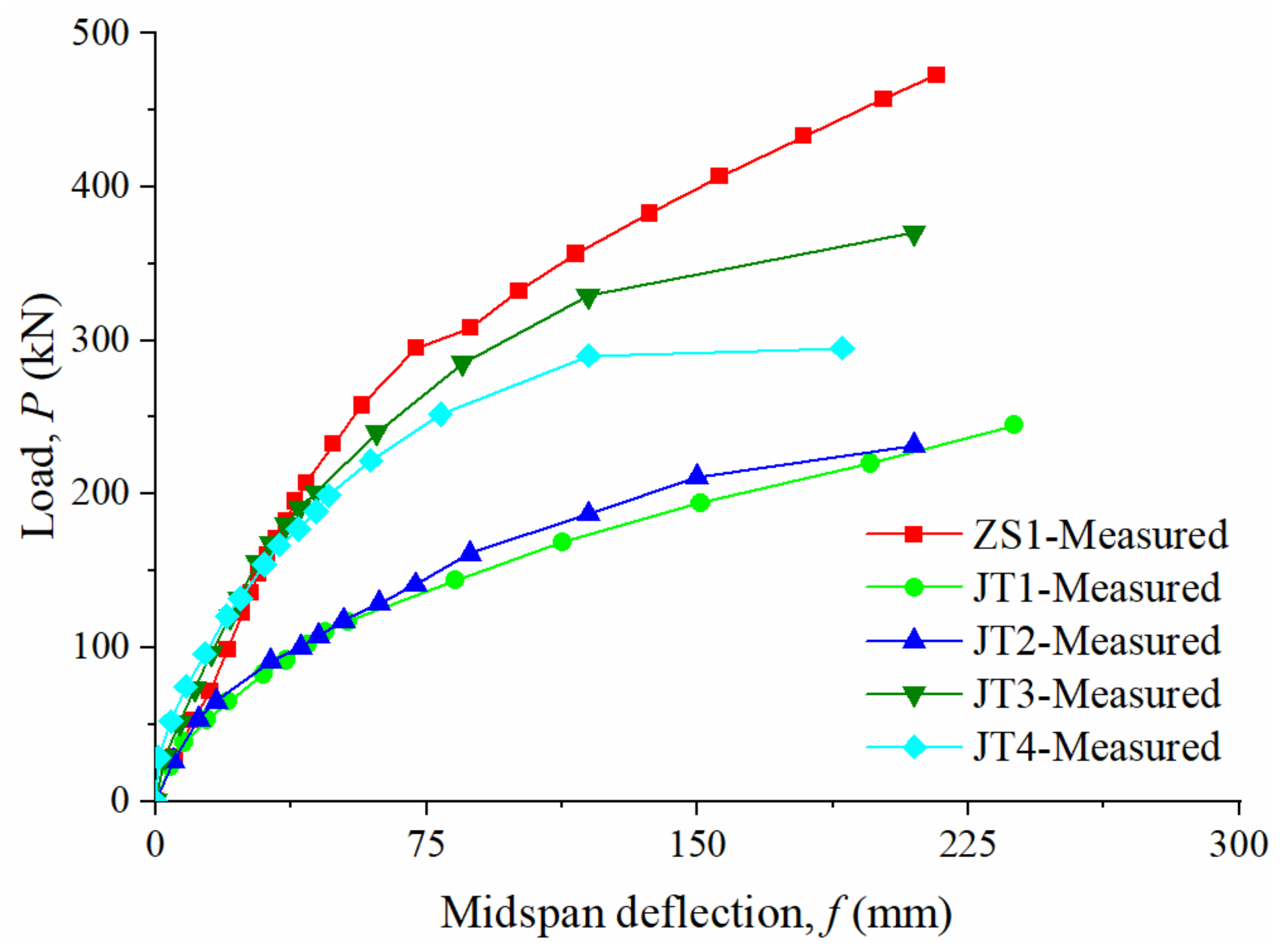
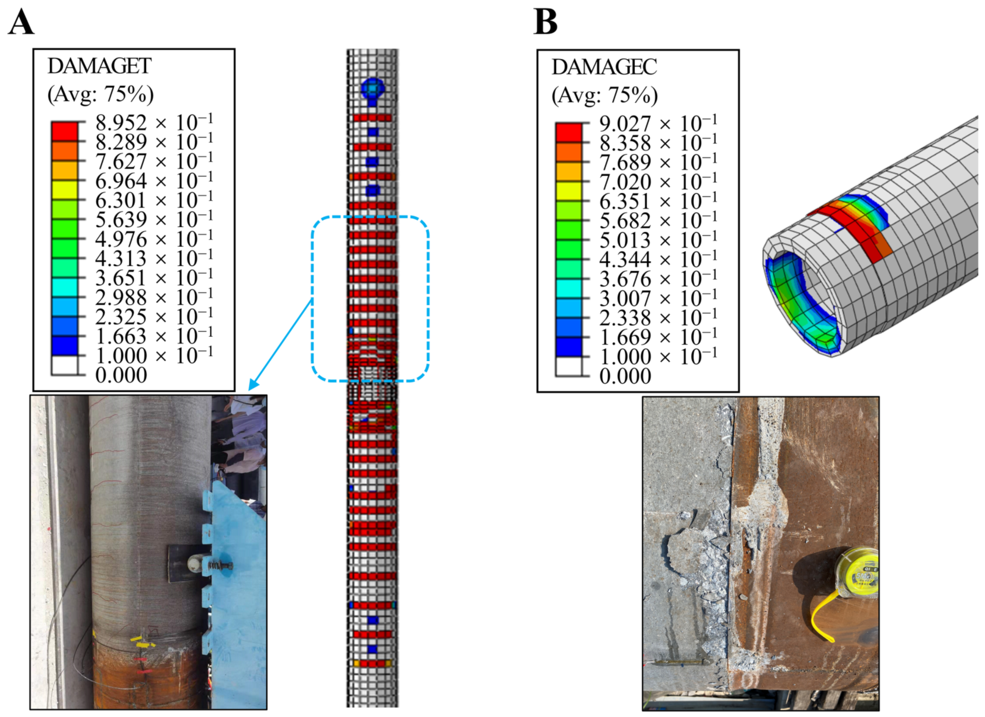
4.1. Failure Characteristics of Test Specimens

All five groups of specimens exhibited bending damage. After the PRC pipe pile shaft specimen ZS1 reached the cracking load, a very small number of cracks appeared in the pile near the midspan position. Subsequently, the cracks extended upward gradually, and the midspan deflection increased. Finally, the concrete in the midspan compression zone was crushed and the pile could not be loaded further. Therefore, under the condition of bending, the failure mode of the PRC pipe pile was different from that of the PHC pipe pile. The PHC pipe pile was generally damaged due to the breaking of steel bar or excessive concrete cracks in the tension area [6,42,43]. The damage process and final damage pattern of the four groups of PRC pipe pile joint specimens were basically the same, and the field damage form is shown in Figure 6. After loading to the cracking load, a small amount of tension cracks appeared at the edge of the tensile zone in the bending section of the joint specimens, and the contact between the pile hoop and the pipe pile showed signs of disconnection, but no damage occurred at this time; as the loading continued, the cracks in the tensile zone gradually extended to the surrounding area, but the width was less than 1.5 mm, the midspan deflection of the joint increased, and the contact between the pile hoop and the pipe pile disconnected clearly, and finally the joint specimens were all damaged when the concrete at the upper edge of the pile hoop was crushed. After removing the pile hoop and cutting the end plate after the test, it was found that the end plate of JT1 and JT2 was disconnected from the concrete by 4.6~11.0 mm, and the end plate of JT2 joint showed drum-shaped tensile yield deformation with the maximum deformation of 8.0 mm, as detailed in Figure 6B. It must be added that the joint was only welded to a certain depth of the outer ring and inner ring, and the middle contact part was not welded. Under bending loading conditions, the middle gap formed due to joint deformation, which was not a crack caused by layered tearing.
The strain measurement points were arranged at the bottom, middle, and top near the joint (see Figure 3) to obtain the strain variation characteristics of the joint under different loads, as shown in Figure 7, where positive strain values indicate tension and negative values indicate compression. Before the cracking load, the strain of the pile concrete attached to the joint developed slowly, and the load and strain were roughly linear, and the cracking load became an obvious inflection point, after which the strain change accelerated; in addition, the strain at the top and bottom of the weld was basically linear and significantly smaller than the strain of the pile concrete, and the weld was not damaged considering the practical condition.

4.2. Bending Bearing Capacity

Figure 8 shows the load-midspan deflection curves of each specimen. The calculated crack moment Mcr and ultimate bending moment Mu as well as the measured crack moment Mcr and ultimate bending moment Mu of each specimen and their comparison are given in Table 3. From Figure 8 and Table 3, it can be seen that:
(1) The measured pile crack moment Mcr near the PRC pipe pile joint was 15–23% larger than the calculated pile crack moment Mcr (mean value 20%), which was slightly larger than the measured value of ZS1 pile; with JT1 as the reference, the measured crack moment Mcr of the joint was only 4–7% higher when the comprehensive reinforcement ratio was increased by 1–2 times. When multiple sections of piles were involved in the design of pipe piles for foundation support, the strength at the joints should be considered for reduction [6]. The ratio between the measured ultimate bending moment of the joint and the calculated crack moment of the pile in this test was 1.63–2.30; therefore, it also further verified that under the national standard JGJ/T 406-2017 [6] it is safe and reasonable to adopt the crack moment of the pile without considering the effect of non-prestressed reinforcement as the design value of the joint bending moment of the pipe pile under the condition of the comprehensive subfactor of 1.25 for the load of the supporting structure.
(2) The measured ultimate bending moment Mu of pile specimen ZS1 was slightly larger than its calculated value Mu, but the measured ultimate bending moment Mu of the joint specimen was smaller than the calculated ultimate bending moment Mu of the pile, which was only 58–87% of the calculated value, among which the measured ultimate bending moment Mu of joint JT1 was 81% of the measured value of pile ZS1. In one previous study [6], seven sets of bending tests carried out on PRC pipe pile joints had 500 mm diameter and 1000 mm wall thickness, and the bending strength of PRC pipe pile joints was improved by about 10% compared with PHC pipe pile joints, but the measured ultimate bending moment was only 64–81% of the measured value of the pile shaft, and similar results were also obtained in three sets of PHC pipe pile joint tests in another study [8]. It can be seen that it is difficult for the traditional welded joint to achieve the bending strength of the pipe pile shaft; the pipe pile can improve the bending bearing capacity of the pile shaft by compound reinforcement, but it does not improve the bending bearing capacity of the pipe pile joint to the same extent.
(3) Compared with JT2 without anchored reinforcement, the measured ultimate bending moment of JT3 with prestressed reinforcement anchored only increased by 9%, but JT4 with rebar anchored decreased by 9%. The increase of anchored reinforcement did not effectively improve the bending strength of the joint, which may be related to its failure to substantially improve the discontinuity at the joint.
In general, the higher the longitudinal reinforcement ratio of the pipe pile in the reasonable range, the higher its positive cross-sectional bending strength [6,44]. Referring to the standard method [28], the height of the relative limit pressure zone of the prestressed concrete pipe pile members in this test was 0.43, and thus the maximum reinforcement ratio was calculated to be 4.0 and 1.6% when the longitudinal reinforcement was HRB400 reinforcement or prestressed reinforcements, respectively. When the area ratio of non-prestressed and prestressed reinforcements was 1–3, the maximum comprehensive reinforcement ratio was 2.8–3.4%. For the selected pipe piles of JT2 and JT4, the comprehensive reinforcement ratio was 4.6 and 7.6%, which is an excess reinforcement design. During the production of pipe piles, the larger reinforcement ratio is not conducive to the uniform mixing and compacting of concrete admixture during the centrifugal forming of pipe piles, which has an impact on the quality of the pile concrete construction [45]. Therefore, the joint bending strength of JT2 and JT4 with higher reinforcement ratio in this test was lower, where the measured ultimate bending moment of JT4 was 87% of that of JT1, which is probably related to the excess reinforcement, and the excess reinforcement damage occurred while the concrete quality was reduced, and its load-midspan deflection curve also showed a significant steep drop at a later stage, as shown in Figure 8.

4.3. Numerical Model Validation

Figure 9 shows the load-midspan deflection curves of the numerically analyzed joint specimens, and Figure 10 shows the damage characteristics of the pipe pile concrete under a loading displacement of 250 mm. In general, the numerical calculation results simulated the deformation characteristics of the joint and the damage of the material better, which indicates that the established model and the selected parameters were reasonable. Therefore, it is more reliable to use the model as the basis for analyzing the joint forces and the effects of different factors.

4.4. Mechanisms of Stress and Deformation of Connection Joints

Under vertical loading conditions, the upper part of the pipe pile at both ends of the joint is under pressure and the lower part is under tension. The pipe pile joint is made of various kinds of steel and connected with the reinforcement, and the force and deformation are complicated, which is also reflected in other joint types [15,26]. Figure 11 shows the stress distribution characteristics of the pipe pile joint JT1 under loading displacement of 250 mm. The maximum tensile stress of the pile hoop was about 190 MPa, and no material yielding occurred; most of the tensile side of the end plate reached the material yielding (225 MPa), and the stress at the local prestressed reinforcement anchoring point reached 375 MPa, which was close to the material tensile strength; the tensile stress of the prestressed reinforcements and non-prestressed reinforcements at the joint part reached the yielding strength of the corresponding steel, but far from the tensile strength, and no damage to the steel material occurred.
The prestressed reinforcements were anchored on the joint end plate, and during the loading process, the tensioned side of the end plate was subjected to significant tension, and the local stress concentration yielded, eventually showing a drum-shaped tension yielding deformation, which was not found in previous tests [8,14,46], as shown in Figure 12A. In particular, a variety of end plate stiffness values was considered in the numerical analysis, and it was found that increasing only the end plate thickness or stiffness did little to improve the end plate deformation. Due to the limited bonding strength of the pile hoop, end plate, and pipe pile concrete [46], the pile hoop, end plate, and pipe pile concrete were gradually disengaged after cracking load. Under the ultimate load, the end plate and pile head concrete were pulled apart by 4.6 mm–11.0 m in the field test, and the lower edge of the pile hoop was disengaged from the pipe pile by 3.0–8.0 mm, as shown in Figure 12B. As can be seen, the current welding conditions showed a large deformation of the pipe pile joint, weakening its bending strength.
Field tests and numerical analysis showed that the bending strength of the welded joint of PRC pipe pile was lower than that of the pipe pile shaft; under the bending condition of the joint, tensile cracks appeared first in the concrete of the pipe pile on the tensile side and the strain increased, and with the yield deformation of the end plate and tensile reinforcement, the deformation of the joint increased significantly; due to the obvious difference in the elastic modulus between the pile hoop and the pipe pile, the stress concentration was easily generated in the pressure area of the two joints, which caused the concrete at the upper edge of the joint of PRC pipe pile to reach the ultimate compressive strain, and the joint was crushed locally and destroyed.

4.5. Influencing Factors on Bending Strength of Joints

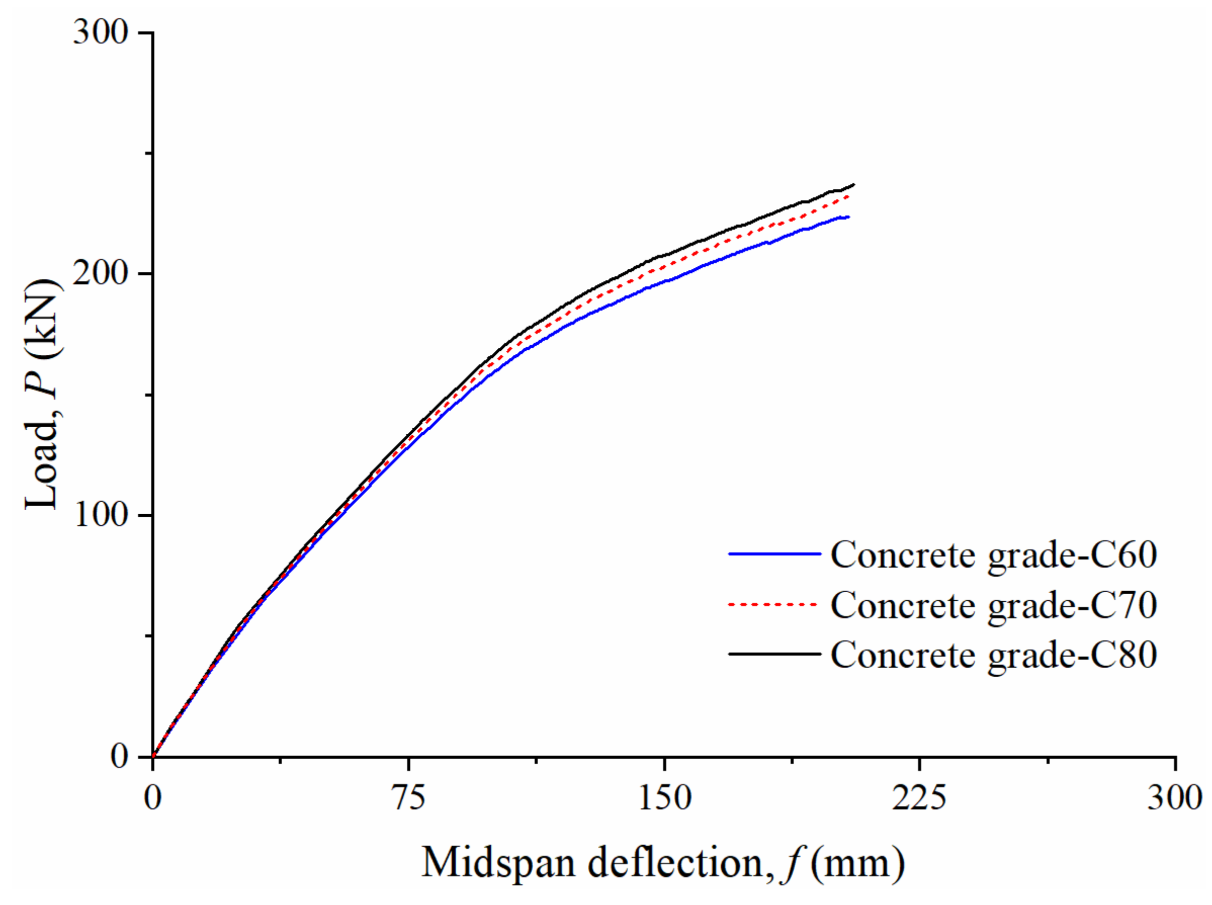
4.5.1. Concrete Strength

The crushing failure of concrete in the compression area occurred in the field tests, which showed that the concrete strength grade affected the bending strength of the joint. At present, there is not enough research on the performance of high-strength concrete above C80 [47,48]. This time, concrete strength of C60, C70, and C80 was used for analysis, and the material parameters of concrete are shown in Table 2. The numerical results are shown in Figure 13.
Under the condition of midspan deflection 200 mm, the bending strength of pipe pile using C80 concrete was only about 1–4% higher than that of C60 and C70. The strength grade of C60~C80 concrete had limited effect on the bending bearing capacity of pipe pile joints. However, as the concrete strength grade increased, the height of the relative boundary pressure zone of the pipe pile cross-section was reduced, which can enhance the suitable range of pipe pile reinforcement. Therefore, the linkage increase of reinforcement ratio and concrete strength grade can be adopted to effectively enhance the bending strength of the pipe pile shaft or pipe pile joint.

4.5.2. Effective Precompression Stress of Concrete

As required by the standard GB 50010-2010 [28], the tension control stress σcon of prestressed reinforcement in pipe piles was limited to 0.5–0.9 times the standard value of the tensile strength of steel reinforcement fptk, which is generally taken as 0.7 times of fptk. To analyze the effect of the effective precompression stress of concrete, three cases of σcon = 0.5fptk, 0.7fptk, and 0.9fptk were considered, corresponding to 70, 100, and 130% of the reference value (σcon = 0.7fptk) of prestress, respectively.
The calculation results are shown in Figure 14. Similar to the bending behavior of the pipe pile shaft [44], the precompression stress of concrete also had a great influence on the bending performance of the joint, and the higher the precompression stress, the better the bending strength of the joint. When the midspan deflection was 200 mm, the bending moments under 70, 100, and 130% of the reference value of prestress were 2110, 2336, and 2476 kN·m, respectively. The bending performance under the condition of 130% prestress was 6% higher than that under the reference value. Clearly, with the increase of midspan deflection, the improvement of bending performance will be more obvious. Figure 14B,C shows the damaged concrete materials under different prestresses (f = 200 mm). The higher the effective prestressed force, the weaker the concrete damage in tension and the more enhanced damage in compression; under the same load, the tension cracks were controlled, and the joint tended to crush the concrete in the compression zone. In engineering applications, high-strength prestressed reinforcements can be used to meet the higher prestress applied to improve the bending strength of the joint.

4.5.3. Joint Connection Mode

The connection mode affects the bending performance [14,15]. To analyze the effect of strengthening the joint connection, three cases were simulated: (1) full section welding of the end plate, which was the limit of the welded connection; (2) mechanical long pin (1000 mm-long) connection, implanted with concrete at the end of the pipe pile; (3) short pin (48 mm-long) connection with only anchored end plate. The “tie” connection mode was adopted for welded connection as well as the pin contact with the end plate and concrete.
The results are shown in Figure 15. The bending strength of the short pins was slightly improved, and the load-midspan deflection curves under the conditions of fully welded end plate and long pin connections basically overlapped with the pile material curves. It could be seen that full welding of end plates and long pins strengthened the continuity of pipe pile joints, which effectively transferred the joint forces to the pile concrete and made its bending strength close to that of the pile material. In particular, the pin type mechanical joint was also a proven efficient connection method [49]. It must be stated that although the above joint strengthening measures are difficult to fully achieve in engineering practice, the joint connection structure can be optimized to enhance the bending strength by using Rachel reinforcement connection implanted into concrete, filling high-strength structural bar glue between end plates, and adding ribs on the inner wall of the pile hoop.

5. Conclusions

In this study, the bending performance and influencing factors of connection joints of large diameter PRC pipe piles were analyzed by full-scale bending tests and numerical simulation. The main conclusions are as follows:
(1)
The crack resistance of PRC pipe pile welded joints was comparable to that of the pipe pile shaft, and it is safe and reasonable to adopt the crack moment of the pile without considering the effect of non-prestressed reinforcement as the design value of the joint bending moment of the pipe pile.
(2)
The bending strength of welded joint of PRC pipe pile was lower than that of the pile shaft. The main failure mode was that the tensile yield of the end plate was in the shape of a drum, the pile hoop and end plate were obviously separated from the pipe pile, and the concrete on the upper edge of the pile hoop was crushed.
(3)
The bending strength of the joint with fully welded end plates and long pin connection was close to that of the pile shaft. Rachel reinforcement connection implanted into concrete and filled with high-strength structural bar glue between end plates can be used to maintain the continuity of the joint section and force and improve the bending strength of the joint.
(4)
The bending capacity of the joint can be improved by increasing the strength grade and reinforcement ratio of concrete at the same time, or by strengthening the precompression stress of concrete. However, the comprehensive reinforcement ratio of PRC pipe pile with a pile diameter of 1000 mm and a wall thickness of 130 mm should not be more than 3.4%, otherwise brittle failure will occur easily.

Author Contributions

Conceptualization, M.T. and Y.Q.; methodology, M.T. and Z.L.; software, Z.L.; validation, Z.L. and Y.Q.; formal analysis, Z.L.; investigation, Z.L. and Y.Q.; resources, M.T. and Y.Q.; data curation, Z.L. and Y.Q.; writing—original draft preparation, Z.L.; writing—review and editing, M.T., Z.L. and Y.Q.; visualization, Z.L.; supervision, M.T.; project administration, M.T.; funding acquisition, M.T. and Z.L. All authors have read and agreed to the published version of the manuscript.

Funding

This research was funded by National Natural Science Foundation for Young Scientists of China, grant number 51908225; China Postdoctoral Science Foundation, grant number 2021M690784; Science and Technology Plan of Guangzhou Municipal Construction Group; grant number 2021–KJ040.

Institutional Review Board Statement

Not applicable.

Informed Consent Statement

Not applicable.

Data Availability Statement

Not applicable.

Conflicts of Interest

The authors declare no conflict of interest.

References

  1. Wu, Z.P.; Yang, X.D.; Bao, L. Application research of prestressed high strength concrete pipe pile in construction. Appl. Mech. Mater. 2012, 193–194, 1393–1396. [Google Scholar] [CrossRef]
  2. Zhao, S.; Huang, G.; Ma, S.; Zhou, W.; Zhang, X. Application of precast concrete pipe piles in a deep excavation project. Chin. J. Geotech. Eng. 2014, 36 (Suppl. S1), 91–96. [Google Scholar] [CrossRef]
  3. Gao, W.S.; Liu, J.L.; Zhao, X.G.; Qiu, M.B. Some understanding of prestressed concrete pipe pile in engineering application. Rock Soil Mech. 2015, 36 (Suppl. S2), 610–616. [Google Scholar] [CrossRef]
  4. Du, X.X.; Hu, R.; Yuan, H.X.; Cheng, X.Y.; Lin, C. Study on flexural behavior of prestressed concrete pipe pile with hybrid reinforcement. China Civ. Eng. J. 2019, 52, 44–52. [Google Scholar] [CrossRef]
  5. Ren, J.W.; Xu, Q.B.; Chen, G.; Yu, X.D.; Gong, S.F.; Lu, Y. Full-scale experimental study of the seismic performance of pretensioned spun high-strength concrete piles. Soil Dyn. Earthq. Eng. 2022, 162, 107467. [Google Scholar] [CrossRef]
  6. CABR (China Academy of Building Research). JGJ/T 406-2017 Technical Standard for Prestressed Concrete Pipe Pile; China Architecture & Building Press: Beijing, China, 2017. [Google Scholar]
  7. Liu, F.R.; Jia, L.; Li, C. The test study on welding joint flexural bearing capacity of prestressed concrete hollow square pile. J. Wuhan Univ. Technol. 2008, 30, 105–108. [Google Scholar] [CrossRef]
  8. Huang, G.L.; Yan, R.H.; Zhou, W.Y.; Chen, Q. Experimental study on joint flexural bearing capacity of prestressed concrete pipe piles. J. Jiangsu Univ. Technol. 2011, 25, 209–212. [Google Scholar]
  9. Li, Z.Y.; Ke, Z.B.; Liu, D.J.; Lu, Z.T.; Guo, Y. Tests on PHC pipe pile joint quality by low-strain reflected wave method. Chin. J. Geotech. Eng. 2011, 33 (Suppl. S2), 209–212. [Google Scholar]
  10. Chen, C.; Yang, L.D. Experimental research on concrete permeability of underground structure. Rock Soil Mech. 2011, 32, 2379–2385. [Google Scholar] [CrossRef]
  11. Huang, F.M.; Cao, Z.S.; Jiang, S.H.; Zou, G.B.; Guo, Z. Landslide susceptibility prediction based on a semi-supervised multiple-layer perceptron model. Landslides 2020, 17, 2919–2930. [Google Scholar] [CrossRef]
  12. Huang, F.M.; Cao, Z.S.; Guo, J.F.; Jiang, S.H.; Guo, Z. Comparisons of heuristic, general statistical and machine learning models for landslide susceptibility prediction and mapping. CATENA 2020, 191, 104580. [Google Scholar] [CrossRef]
  13. Chang, Z.; Du, Z.; Zhang, F.; Huang, F.; Chen, J.; Li, W.; Guo, Z. Landslide susceptibility prediction based on remote sensing images and GIS: Comparisons of supervised and unsupervised machine learning models. Remote Sens. 2020, 12, 502. [Google Scholar] [CrossRef] [Green Version]
  14. Xu, Q.B.; Chen, G.; He, J.F.; Gong, S.F.; Xiao, Z.B. Flexural performance experiment of connection joint for composite reinforcement concrete prefabricated square piles. J. Zhejiang Univ. Eng. Sci. 2017, 51, 1300–1308. [Google Scholar] [CrossRef]
  15. Zhou, J.W.; Wang, Y.F.; Gong, S.F.; Zhang, A.H.; Liu, C.B.; Fan, H. Study on flexural behavior of prestressed concrete square pile connection joint with resilient clamping. Build. Struct. 2020, 50, 121–127. [Google Scholar] [CrossRef]
  16. Qi, J.L.; Gong, S.F.; Zhou, Z.D.; Liu, Y.S. Study on flexural behavior of prestressed concrete special-shaped square pile connection joint with bolt-shackle. Build. Struct. 2021, 51, 105–109. [Google Scholar] [CrossRef]
  17. Wang, B.; Qi, L.; Yang, Y.D. Experimental study on bending resistance of new type joint of prestressed concrete pipe pile. Symmetry 2022, 14, 1920. [Google Scholar] [CrossRef]
  18. Huang, F.M.; Zhang, J.; Zhou, C.B.; Wang, Y.H.; Huang, J.S.; Zhu, L. A deep learning algorithm using a fully connected sparse autoencoder neural network for landslide susceptibility prediction. Landslides 2020, 17, 217–229. [Google Scholar] [CrossRef]
  19. Jiang, S.H.; Huang, J.S.; Huang, F.M.; Yang, J.H.; Yao, C.; Zhou, C.B. Modelling of spatial variability of soil undrained shear strength by conditional random fields for slope reliability analysis. Appl. Math. Model. 2018, 63, 374–389. [Google Scholar] [CrossRef]
  20. Tang, M.X.; Ling, Z.; Liu, C.L.; Hu, H.S. Influence of pile toe type on bearing capacity of rock-socketed DPC piles. Chin. J. Rock Mech. Eng. 2022, 41 (Suppl. S1), 3053–3062. [Google Scholar] [CrossRef]
  21. Chen, G.; Zhou, Q.H.; Xu, Q.B.; Gong, S.F.; Xiao, Z.B.; Liu, C.B. Study on flexural performance of prestressed steel strand reinforced ultra-high strength concrete pipe piles. J. Build. Struct. 2019, 40, 173–182. [Google Scholar] [CrossRef]
  22. Ling, Z.; Wu, J.B.; Wang, W.D. Numerical analysis of bearing behavior of the prebored precast pile with an enlarged base. Adv. Civ. Eng. 2021, 2021, 1505482. [Google Scholar] [CrossRef]
  23. Liu, H.L.; Kong, G.Q.; Ding, X.M.; Chen, Y.M. Performances of large-diameter cast-in-place concrete pipe piles and pile groups under lateral loads. J. Perform. Constr. Facil. 2013, 27, 191–202. [Google Scholar] [CrossRef]
  24. Wang, A.; Zhang, D.; Deng, Y. Lateral response of single piles in cement-improved soil: Numerical and theoretical investigation. Comput. Geotech. 2018, 102, 164–178. [Google Scholar] [CrossRef]
  25. Wei, D.M.; Wang, P. Investigation on corrosion of welded joint of prestressed high-strength concrete pipe piles. Procedia Eng. 2017, 210, 79–86. [Google Scholar] [CrossRef]
  26. Lu, L.; Han, S.; Chen, Z.; Wang, G.; Wang, Y.; Zhao, K. Study on bending performance of prefabricated square pile with socket and spigot joint. J. Build. Struct. 2018, 39, 153–161. [Google Scholar] [CrossRef]
  27. CBMF (China Building Materials Federation). GB 13476-2009 Pretensioned Spun Concrete Piles; Standards Press of China: Beijing, China, 2009. [Google Scholar]
  28. CABR (China Academy of Building Research). GB 50010-2010 Code for Design of Concrete Structures (2015 Edition); China Architecture & Building Press: Beijing, China, 2015. [Google Scholar]
  29. Sun, X.F.; Fang, X.S.; Guan, L.T. Mechanics of Materials, 5th ed.; Higher Education Press: Beijing, China, 2009. [Google Scholar]
  30. Wahalathantri, B.L.; Thambiratnam, D.P.; Chan, T.H.T.; Fawzia, S. A material model for flexural crack simulation in reinforced concrete elements using ABAQUS. In Proceedings of the First International Conference on Engineering, Designing and Developing the Built Environment for Sustainable Wellbeing, Queensland University of Technology, Brisbane, Australia, 28 April 2011; pp. 260–264. [Google Scholar]
  31. Liang, J.H.; Fan, Q.Y.; Qin, K. Influence of Karst Caves on the Pile’s Bearing Characteristics-A Numerical Study. Front. Earth Sci. 2022, 9, 754330. [Google Scholar] [CrossRef]
  32. Mercan, B.; Schultz, A.E.; Stolarski, H.K. Finite element modeling of prestressed concrete spandrel beams. Eng. Struct. 2010, 32, 2804–2813. [Google Scholar] [CrossRef]
  33. Nguyen, T.H.A.; Bui, T.Q.; Hirose, S. Smoothing gradient damage model with evolving anisotropic nonlocal interactions tailored to low-order finite elements. Comput. Methods Appl. Mech. Eng. 2018, 328, 498–541. [Google Scholar] [CrossRef]
  34. Yuen, T.Y.; Wen, T.-H.; Hung, C.-C.; Zhang, H.; Pham, P.A.H.; Deng, Y. An eigendecomposition-based and mesh-sensitivity reduced constitutive model for nonlinear analysis of concrete structures under non-proportional cyclic loading. J. Build. Eng. 2022, 47, 103875. [Google Scholar] [CrossRef]
  35. Lubliner, J.; Oliver, J.; Oller, S.; Onate, E. A plastic-damage model for concrete. Int. J. Solids Struct. 1989, 25, 299–326. [Google Scholar] [CrossRef]
  36. Lee, J.; Fenves, G.L. A plastic-damage model for cyclic loading of concrete structures. J. Eng. Mech. 1998, 124, 892–900. [Google Scholar] [CrossRef]
  37. Lee, J.; Fenves, G.L. A plastic-damage concrete model for earthquake analysis of dams. Earthq. Eng. Struct. Dyn. 1998, 27, 937–956. [Google Scholar] [CrossRef]
  38. Abaqus. Analysis User’s Manual, Version 6.14; Dassault Systemes Simulia Corp.: Providence, RI, USA, 2016. [Google Scholar]
  39. Yang, Z.J.; Lei, Y.Q. Finite element analysis of the shear behavior of prestressed high-strength concrete piles. Eng. Mech. 2020, 37 (Suppl. S1), 200–207. [Google Scholar] [CrossRef]
  40. Hu, R. Research on Shear and Flexural Behaviour of Prestressed Concrete Pipe Pile with Hybrid Reinforcement; Wuhan University: Hubei, China, 2018. [Google Scholar]
  41. He, L.; Wang, J.L. Method of equivalent load and temperature reduction on prestressing tendon for effective prestress simulation. J. Highw. Transp. Res. Dev. 2015, 32, 75–80. [Google Scholar] [CrossRef]
  42. Tang, G.Z.; Wang, Q.; Yu, Q. Discussion on calculating method of cracking resistance and ultimate bending moment of pretensioned spun concrete piles. Ind. Constr. 2004, 34, 57–59. [Google Scholar] [CrossRef]
  43. Huang, G.L.; Yan, R.H.; Zhou, F.; Mei, G.X. Experimental study and discussion on the flexural capacity of prestressed high strength concrete supporting piles. Build. Struct. 2012, 42, 113–116. [Google Scholar] [CrossRef]
  44. Huang, F.Y.; Wu, S.W.; Luo, X.Y.; Chen, B.C.; Lin, Y.W. Pseudo-static low cycle test on the mechanical behavior of PHC pipe piles with consideration of soil-pile interaction. Eng. Struct. 2018, 171, 992–1006. [Google Scholar] [CrossRef]
  45. Liu, Y.; Tan, Y.S. Studies on longitudinal reinforcement ratio of flexural RC member. Archit. Technol. 2006, 40, 389–390. [Google Scholar] [CrossRef]
  46. Yu, P. Experimental Study on the Influence of Hoop or Clamp Joint on the Mechanical Behavior of PRC Pipe Pil; Zhengzhou University: Zhengzhou, China, 2021. [Google Scholar]
  47. Guo, Y.B.; Gao, G.F.; Jing, L.; Shim, V.P.W. Response of high-strength concrete to dynamic compressive loading. Int. J. Impact Eng. 2017, 108, 114–135. [Google Scholar] [CrossRef]
  48. Minh, H.-L.; Khatir, S.; Wahab, M.A.; Cuong-Le, T. A concrete damage plasticity model for predicting the effects of compressive high-strength concrete under static and dynamic loads. J. Build. Eng. 2021, 44, 103239. [Google Scholar] [CrossRef]
  49. Ptuhina, I.; Alzhanova, R.; Akhatuly, A.; Maier, V. Comparative Analysis of Pile Joints. Adv. Mater. Res. 2014, 1082, 270–276. [Google Scholar] [CrossRef]
Figure 1. Schematic diagram of reinforcement of PRC pipe piles: (A) ZS1, JT1, and JT2; (B) JT3; (C) JT4; (D) cross-sectional reinforcement and end plate connection (unit: mm).
Buildings 13 00119 g001
Figure 2. Construction of pipe pile joint.
Buildings 13 00119 g002
Figure 3. Schematic diagram of bending test.
Buildings 13 00119 g003
Figure 4. Schematic diagram of finite element meshing.
Buildings 13 00119 g004
Figure 5. Plastic stress–strain curves and damage evolution curves of C80 concrete: (A) compression; (B) tension.
Buildings 13 00119 g005
Figure 6. Failure modes of pipe pile joints: (A) JT1; (B) JT2; (C) JT3; (D) JT4.
Buildings 13 00119 g006
Figure 7. Strain variation characteristics of joint JT2.
Buildings 13 00119 g007
Figure 8. Load-midspan deflection curves of bending tests.
Buildings 13 00119 g008
Figure 9. Comparison between numerical simulation and bending test.
Buildings 13 00119 g009
Figure 10. Damage of pipe pile concrete (f = 250 mm): (A) tension; (B) compression.
Buildings 13 00119 g010
Figure 11. Stress characteristics of pipe pile joint JT1 (unit: MPa): (A) pile hoop and end plate; (B) prestressed steel rods; (C) non-prestressed reinforcements.
Buildings 13 00119 g011
Figure 12. Deformation of pipe pile joint (display enlarged by 10 times, unit: mm): (A) end plate; (B) pile hoop.
Buildings 13 00119 g012
Figure 13. Influence of strength of concrete on the bending strength of joints.
Buildings 13 00119 g013
Figure 14. Influence of precompression stress of concrete on the bending strength of joints: (A) load-midspan deflection curves; (B) tension damage; (C) compression damage.
Buildings 13 00119 g014
Figure 15. Influence of connection mode on the bending strength of joints.
Buildings 13 00119 g015
Table 1. Test parameters of PRC piles.
Test
Sample
Pile Length
(m)
Prestressed
Reinforcement
Non-Prestressed
Reinforcement
Hoop
Reinforcement
Anchored
Reinforcement
ρ s
(%)
ZS14044Φ12.622Φ10Φ8/2.0
JT126 + 2644Φ12.622Φ10Φ8/2.0
JT226 + 2644Φ12.622Φ25Φ8/4.6
JT320 + 2044Φ12.622Φ25Φ822Φ12.62.3–5.4
JT420 + 2044Φ12.622Φ25Φ822Φ257.6
Note: ρs is the comprehensive reinforcement ratio; that is, the ratio of the total area of prestressed reinforcement and non-prestressed reinforcement to the effective area of concrete.
Table 2. Material parameters.
MaterialDensity
ρ
(kg/m3)
Elastic
Modulus
E (GPa)
Poisson’s
Ratio
υ
Yield
Strength
fy (MPa)
Compression
Strength
fc (MPa)
Tensile
Strength
ft (MPa)
Prestressed steel rods78002000.301280/1420
Non-prestressed reinforcements78002000.30400/540
End plate78002000.30225/400
Pile hoop78002000.30345/470
C60 concrete2400380.20/50.23.11
C70 concrete2400370.20/44.52.99
C80 concrete2400360.20/38.52.85
Table 3. Bending test results of PRC pipe piles and joints.
Test
Sample
Mcr
(kN·m)
Mu
(kN·m)
M’cr
(kN·m)
M’u
(kN·m)
M’cr/McrM’u/McrM’u/Mu
ZS112852760150329581.172.301.07
JT112852760147824001.151.870.87
JT212853640154222981.201.790.63
JT312853675156525061.221.950.68
JT412853640157620931.231.630.58
Disclaimer/Publisher’s Note: The statements, opinions and data contained in all publications are solely those of the individual author(s) and contributor(s) and not of MDPI and/or the editor(s). MDPI and/or the editor(s) disclaim responsibility for any injury to people or property resulting from any ideas, methods, instructions or products referred to in the content.

