Article

Laws and Numerical Analysis of Surface Deformation Caused by Excavation of Large Diameter Slurry Shield in Upper-Soft and Lower-Hard Composite Stratum

1
School of Civil Engineering, Xi’an University of Architecture & Technology, Xi’an 710055, China
2
Shaanxi Key Laboratory of Geotechnical and Underground Space Engineering, Xi’an 710055, China
*
Author to whom correspondence should be addressed.
Buildings 2022, 12(9), 1470; https://doi.org/10.3390/buildings12091470
Submission received: 12 August 2022 / Revised: 9 September 2022 / Accepted: 13 September 2022 / Published: 16 September 2022
(This article belongs to the Collection Innovation of Materials and Technologies in Civil Construction)

Abstract

:
Due to the large cross-section design of large-diameter shield tunnels, most of the rocks and soils it crosses are composite strata with upper soft and lower hard. In order to reduce the construction cost of shield working shafts, large-diameter shield launching is usually buried at a shallow depth. Based on the typical large-diameter slurry shield tunnel, the following research results were obtained according to field monitoring and PLAXIS 3D finite element simulation. (1) The electronic level is used to monitor the surface settlement, and the field monitoring data were obtained; the surface settlement duration curve at the axis of the shield tunnel during the construction period can be divided into four stages: pre-deformation, shield passing, shield tail exit and shield moving away, of which the surface settlement accounts for the largest proportion during the shield passing. (2) In order to ensure the accuracy of the numerical simulation results, the linear shrinkage of the shield needs to be considered in the modeling. (3) The maximum surface settlement value at the center of the tunnel increases with the increase of the support pressure; when the support pressure exceeds 300 kPa, the surface uplift and the settlement caused by the formation loss will offset, and the surface settlement will decrease instead. The maximum surface settlement value is inversely proportional to the grouting pressure, but with the increase of the grouting pressure, the maximum uplift of the surface continues to increase. (4) With the numerical simulation of excavation step construction, the surface uplift increases with the increase of grouting pressure and shield radius, and decreases with the increase of shield buried depth.

1. Introduction

In order to meet the great demand for urbanization for land resources, and to reduce the environmental effects caused by construction, underground space engineering has been greatly developed [1,2,3,4]. The shield method has been widely developed and applied as a safe, fast, and environment-friendly tunnel construction technology to solve the travel problems of urban residents [5,6,7]. At present, shield method construction is mainly used in metro construction, and the diameter of the shield is generally designed to be 6.2 m [8]. In order to improve the traffic and travel integration level of urban central area, along with the improvement of scientific and technological levels, the construction of large-diameter tunnels has been accelerated in recent years, making it one of the directions of shield development.
During shield tunneling, when the deformation of soil exceeds a certain limit, it will affect the normal use of surrounding construction, and even lead to major engineering disasters [8,9,10,11,12]. Many scholars have deeply studied the law of surface deformation caused by shield tunneling from the perspectives of empirical formula, theoretical analysis, and numerical analysis. Peck [13] has collected a large number of measured data in the process of shield tunneling and analyzed them statistically, and proposed the compound Gaussian formula for surface settlement trough under undrained conditions. Since then, some scholars have revised the surface settlement coefficients Vloss (formation loss per unit length of the tunnel) and i (width coefficient of settling trough) of the Gaussian formula adaptively, which enlarges the applicable scope of the Peck formula [14,15,16].
Sagaseta [17] introduced the source-convergence method to obtain analytical solutions for three-dimensional spatial surface deformation under undrained conditions, Schmidt (1988) [18] challenged this method based on the large difference between the measured values and Sagaseta values, and Sagaseta revised the formula to obtain more accurate results, Since then, some scholars have introduced new theories to study the analytical solution, which has improved the calculation accuracy of the analytical solution [19,20,21].
With the improvement of computer software and hardware, numerical analysis technology has been widely used in recent years. Notable achievements have been made in the analysis of face stability, shield excavation simulation, and shield grouting [22,23,24,25].
The above research has laid a good theoretical and practical foundation for this paper, but few studies involve large-diameter slurry shield tunnels. In recent years, with the continuous expansion of the practice of large-diameter shield tunneling, it is urgent to study the laws of environmental effects caused by large-diameter shield tunneling. Due to the large cross-section design of large-diameter shield tunnels, most of the soils it crosses are composite strata with upper soft and lower hard, and in order to reduce the construction cost of shield working shafts, shield tunnels are usually designed to start with shallow overburden. Therefore, this paper is based on the engineering practice of typical large-diameter slurry shield tunneling in the No.01 section of Hangzhou Tianmushan Road to Huancheng North Road upgrade project. According to the field monitoring data, the ground settlement caused by large-diameter slurry shield tunnel excavation is divided into four stages, and the proportion of tunnel settlement in each stage is summarized. Through numerical simulation, the influence of linear shrinkage of the shield on the rationality of numerical simulation modeling is analyzed, and the influence of key construction parameters of large-diameter slurry shield on surface settlement deformation is comprehensively analyzed. The research results can provide a reference for the design and construction of a large-diameter slurry shield.

2. Overview of the Test Section

An air cushion slurry shield machine with a diameter of 13.46 m was used in a tunnel in Hangzhou. The total length of the tunnel is designed to be about 1760 m. After starting from the 7.56 m overburden of the No. 1 well, the maximum longitudinal slope is 3% to the lowest point, and then it rises to 13 m of covering the soil in No. 2 working well with 2.5% and 0.3% longitudinal slope, The average covering soil thickness of the tunnel is about 0.6 times the diameter of the tunnel. The overview of the shield design is shown in Figure 1a. The soil conditions along the tunnel are very complicated. As well, the upper part of the tunnel mainly passes through silt clay, silty clay, crushed stone with cohesive soil, and gravel silty clay. the lower side passes through fully, strongly, and moderately weathered gravel-bearing siltstone and strongly and moderately weathered tuff strata, and the tunneling section as a whole is a typical upper soft and lower hard stratum. As shown in Figure 1b.

3. Monitoring and Analysis of Surface Deformation of Large Diameter Shield Tunnel

The complexity and uncertainty of tunnel excavation make it impossible for theoretical analysis to fully and accurately predict the settlement and deformation of the ground surface caused by tunnel excavation. On-site monitoring can reflect the comprehensive effect of various factors on surface deformation during the construction process, so it is very important to monitor the ground surface settlement caused by tunnel excavation under theoretical guidance. In this paper, a large number of on-site monitoring data is collected to study the law of surface longitudinal and transverse during shield excavation.

3.1. Monitoring Scheme

The on-site monitoring scheme is determined according to (the technical code for monitoring of Urban Rail Transit Engineering) (GB50911-2013). The layout plan of the measuring points is as follows: with the 100 m range of the entrance and exit section, a surface settlement monitoring section is laid out at intervals of 10 m; outside the 100 m range of the entrance and exit section, a surface settlement monitoring section is laid out at intervals of 30 m. The monitoring range is distributed within 35 m on both sides of the shield tunnel, and the monitoring frequency is 12 h/time. Figure 1c,d show the layout plan and site layout of ground settlement monitoring points. From the shield launching shaft to the shield receiving shaft, the surface settlement monitoring section is numbered DBC-X (X is the monitoring section number).

3.2. Diachronic Analysis of Surface Settlement at Axis during Construction Period

With the continuous progress of shield tunneling, surface settlement is constantly developing due to the influence of soil disturbance and ground loss. According to the field monitoring data, the surface transverse curve is obtained. The surface uplift is recorded as a positive value and the surface settlement is recorded as a negative value.
According to the trend analysis of the law of surface settlement caused by tunnel excavation by a large number of scholars, the soil disturbance during tunnel excavation can be divided into four stages [26,27].

3.2.1. The Stage before the Shield Machine Reaches the Working Face

When the shield is excavated to the front of the working face, due to the transfer effect of force and the slurry permeability, the soil in front of the excavation will be pre-disturbed to a certain extent, causing a slight uplift or settlement on the front surface. The degree of disturbance generally weakens with the distance between the shield and the excavation surface increases, and the surface settlement generated at this stage generally accounts for a small proportion of the total settlement, generally within 10% of the total settlement.

3.2.2. Shield Passing Stage

When the shield cutterhead reaches the excavation face, the soil balance of the excavation face will be completely disrupted, tunnel excavation has caused a change in the boundary conditions and the original stress filed in the soil around the tunnel has been destroyed, resulting in a redistribution of stresses. Although there is a slurry air-cushion chamber pressure to balance the face pressure, it cannot accurately balance the water and soil pressure of the face. As well, during the passage of the shield, in order to reduce the friction between the shield movement and the surrounding soil, the shield machine is generally set as a conical shape with a thick front and thin back to reduce the contact between the shield machine and the surrounding soil, as a result, there is a certain construction gap between the excavation section and the lining section, resulting in large surface settlement. In this stage, the surface deformation rate and surface deformation amount increased significantly, and the settlement in this stage generally accounts for 50% to 60% of the total settlement.

3.2.3. Shield Tail Grouting Stage

At this stage, the deformation of the soil layer around the tunnel is basically stable, and the settlement rate tends to ease; after the shield tail has passed, in order to fill the construction gap between the excavation section and the lining section, it is necessary to quickly carry out synchronous grouting. However, due to the grouting pressure, grouting ratio, grouting amount, and the slurry diffusion, the synchronous grouting slurry cannot effectively fill the construction gap, so soil deformation still develops. Therefore, the appropriate grouting ratio and proper grouting pressure are the key factors to control the surface settlement at this stage, and the settlement at this stage generally accounts for 15% to 20% of the total settlement.

3.2.4. Shield Away Stage

After the shield is far away, the tunnel lining has been constructed, and the deformation of the soil around the tunnel is very small. The settlement is mainly affected by the dissipation of excess pore water pressure, grouting slurry, and soil chemical action. The settlement at this stage accounts for 5% to 10% of the total settlement.
Figure 2 shows the surface settlement change and development process curve at the typical monitoring section DBC-3, section DBC-75, and section DBC-80 at the shield axis.
It can be seen from Figure 2a,b that before the shield cutterhead reaches the monitoring section, the stratum is slightly disturbed, and a small amount of uplift and settlement occurs on the surface; during the passage of the shield, the soil disturbance intensified, and shield cutterhead and segment have formation of stratum loss due to the construction gap, which makes the surface settlement rate and settlement amount increase rapidly; the range of severe disturbance is approximately the distance from the initial arrival of the cutterhead to the cutterhead passing through 10 rings, and its value is approximately equal to the length of the shield machine; after the shield machine is passed, it is generally believed that the soil settlement is mainly caused by consolidation, and the settlement tends to be gentle at this time.
From Figure 2c, it can be seen that the monitoring point of the axis settlement at the DBC-80 ring found that the soil body produced a large uplift after the shield passed through. Finding out the reasons, it is found that under normal circumstances, roughly two rings are excavated every day, while at the time of the uplift, the shield tunnels have roughly four rings excavated every day, and the tunneling speed increases greatly; further analysis of the on-site monitoring data found that the shield tunneling rate affects the surface uplift and settlement. When the shield tunneling rate is high, the soil in front of the tunnel face is squeezed by the shield machine, and the pore water pressure has no time to dissipate, so the soil body produces a large uplift. Therefore, during the process of excavation, attention should be paid to the control of the excavation speed, and the excavation rate should be adjusted in time according to the monitoring data.
On the basis of the above analysis, 30 sets of surface settlement monitoring data were selected, and the percentage of settlement composition at each stage was made as shown in Figure 3.
It can be seen from Figure 3 that the first stage settlement accounts for the smallest proportion, which is about 5% of the maximum surface settlement, and the second stage settlement accounts for the largest proportion, accounting for about 65% of the maximum surface settlement, and the third and fourth stage settlement accounts for a similar proportion, which is in the middle proportion, and they account for about 30% of the maximum settlement. This is basically the same as the law of surface deformation caused by large-section tunnel excavation summarized by other scholars.
The surface deformation caused by the tunnel mainly occurs during the passage of the shield in the second stage. The factors affecting the surface settlement in this stage mainly include construction parameters such as cutterhead speed, shield tail grouting, and shield thrust. Therefore, during the construction period, it is necessary to strictly control the above parameters to control the surface settlement to prevent construction accidents caused by excessive surface settlement.

3.3. Variation Law of Surface Transverse

According to the analysis of the monitoring and fitting results of the transverse and deformation of the surface caused by multiple groups of tunnel excavation at home and abroad, it can be seen that the lateral deformation trend of the surface caused by the tunnel excavation conforms to a normal distribution, that is, the lateral deformation of the surface caused by the tunnel excavation can be fitted by a Gaussian curve.
The development process of the transverse trough on the surface of the typical monitoring section during the shield tunneling process is shown in Figure 4. It can be seen from the figure that the surface transverse trough curve of each monitoring section basically conforms to the Gauss distribution. The surface settlement above the axis points of each monitoring section is the largest. The farther away from the tunnel axis, the less disturbance to the soil layer caused by shield construction, and the smaller the surface settlement gradually.

4. Numerical Analysis of Stratum Deformation Caused by Large Diameter Slurry Shield Tunneling

Numerical analysis has been proven to be an effective method to study the law of soil deformation during tunneling. Based on the on-site monitoring data, this paper uses PLAXIS 3D software to conduct a three-dimensional numerical simulation of the excavation process of a large-diameter slurry shield, intends to analyze the soil deformation law caused by the shield excavation, and the numerical simulation results are compared with the measured data to analyze the reasonableness and suitability of the numerical simulation. On this basis, the key construction parameters during the shield tunneling process are analyzed to provide guidance for the design of construction parameters for similar projects.

4.1. Model Excavation Condition Setting and Parameter Selection

The length of the shield machine is 16 m, the width of the tunnel segment ring is 2 m, the outer diameter is 13 m, and the thickness is 0.55 m. The shield is simulated to advance 10 rings, and the initial position of the shield machine excavation surface is at y = 28 m, the range from y = 28 m to y = 30 m represents the initial position of the shield tail grouting section, y = 30 m to y = 46 m represents the shield machine section, the shield is excavated from y = 46 m to 62 m, and each construction step excavates one ring. The top of the tunnel is buried at a depth of 7.56 m. The tunnel excavation conditions are set as shown in Table 1.
In order to make the finite element simulation results conform to the actual situation, the statistical data of construction parameters within 100 m before shield tunneling are selected to set the finite element simulation parameters. The parameter distribution is shown in Figure 5.
It can be seen from Figure 6 that the total thrust of the shield is in the range of 31,707 kN–58,464 kN, the average shield thrust is 52,880.3 kN; the muddy water pressure is in the range of 90~156 kPa, and the average muddy water pressure is 132 kPa. (1) The cross-sectional area of the shield pipe ring is (132 − 11.92) × p/4 = 21.5 m2, and the shield thrust acting on the pipe ring cross-section is σ n = 2460 kPa; (2) According to statistical analysis, the average support pressure of the slurry chamber at the tunnel axis is set to Ps = 150 kPa, with the increasing depth of the tunnel, the average weight of water and soil pressure is about 16 kN/m3 during the construction process, so in the finite element analysis, the support pressure of the excavation face increases by 16 kN/m3 with the depth.
In order to prevent the jamming of the shield machine in the process of shield tunneling and reduce the shield resistance during the shield tunneling process, the diameter of the shield machine from the cutterhead to the shield tail gradually decreases in a conical tunneling state. Simulate the real tunneling pattern by setting the linear shrinkage rate in the model. In this project, the diameter of the shield cutterhead is 13.46 m, the anterior shield is 13.41 m, the middle shield is 13.39 m, and the shield tail is 13.37 m. Compared with the cutterhead, the shield tail is reduced by 0.7%. In the finite element analysis, the first seven rings of the shield shrink from the anterior shield to the shield tail according to the linear shrinkage rate of −0.05%, and the maximum shrinkage rate is 7% at the seventh ring of the shield machine, and the eighth ring of the shield machine shrinks by 7%. In this way, the actual shape of the shield machine is simulated, and takes into account the stratum loss during shield tunneling.

4.2. The Basic Assumption of Model Calculation

In order to simplify the calculation model, reasonable assumptions about the finite element model can not only improve the economy of the finite element calculation, but also improve the calculation speed. According to the above principles, the finite element model is appropriately simplified as follows:
(1)
The horizontal layered distribution of each soil layer, the shield thrust is evenly distributed on the excavation surface, and the buried depth of the tunnel axis remains unchanged during the simulation process;
(2)
Before construction, the self-weight stress of soil and the stress and strain caused by surrounding loads have been completed;
(3)
The influence of groundwater is not considered in the simulation process;
(4)
In the calculation model, the concrete structures such as tunnel segments adopt the elastic model.
(5)
In order to reduce the computational complexity, it is assumed that the soil deformation does not depend on time, and the creep and deformation of the soil are not considered.
(6)
The influence of tectonic stress on soil deformation is ignored, and the initial ground stress only considers the self-weight of the soil.
The above assumptions reduce the fluctuation of ground settlement and can better summarize the rules of numerical simulation results. At the same time, the numerical simulation value will be small because the influence of creep is not considered.

4.3. Three-Dimensional Finite Element Analysis Model of Shield Tunnel

In order to simplify the calculation, a three-dimensional finite element model of a symmetrical half-tunnel was established in Plaxis 3D software according to the uniformity of the soil layer where the tunnel is located. The main lateral influence range of tunnel excavation is within the 3D range, and the longitudinal influence range is −3D~3D. The size of the general model selected in this paper is 120 m (length) × 40 m (width) × 60 m (height). At this time, the foundation soil at the boundary is basically not affected by the tunnel excavation. The bottom of the model adopts fixed constraint; the front, back, left and right are constrained to normal displacement, and the top is free boundary. The model has a total of 33,832 elements and 54,127 nodes.
The Mohr-Coulomb elastic-plastic soil constitutive model is adopted for the numerical simulation of the soil. As a classical constitutive model, it can well describe the failure mode and deformation behavior of the soil [28,29,30]. Table 2 shows the physical and mechanical parameters of soil within the influence range of shield tunnel excavation. The shell of the shield machine is simulated by plate elements, and the rest of the structure is simulated by solid elements. Figure 6 shows the three-dimensional numerical analysis model.

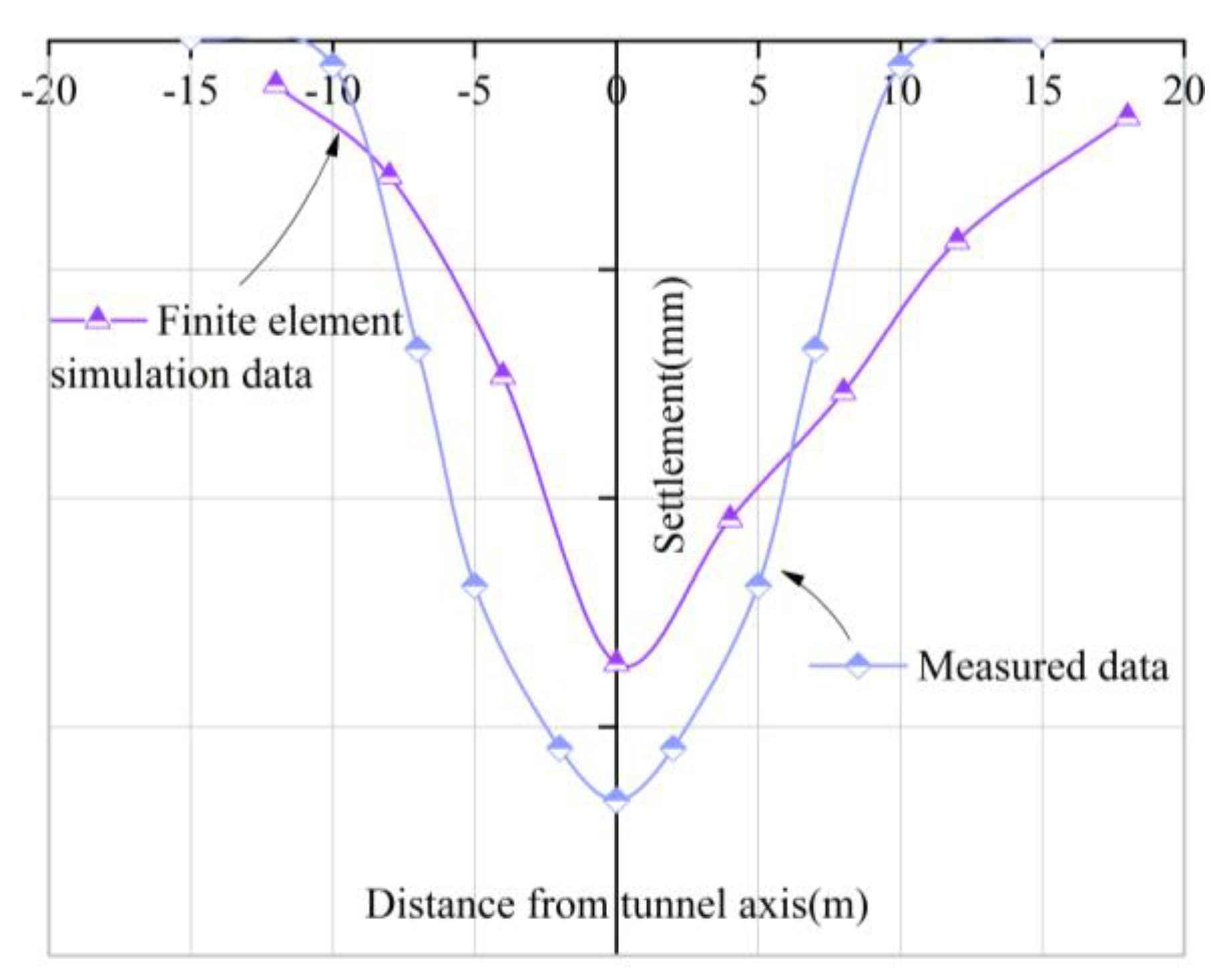
4.4. Test of Model Rationality

Verification of model rationality based on on-site monitoring data and finite element simulation results.
It can be seen from the transverse curve of the surface in Figure 7 that the measured data and the results of the finite element simulation are not completely consistent, and there are certain errors. but the development law of the transverse, curve shape, and settlement value of the measured data and the finite element simulation results are basically consistent. Considering that a certain simplification method is adopted in the finite element simulation process, and because the actual soil conditions cannot be completely simulated, it can be considered that the error range is acceptable. Therefore, it is considered that the established finite element model is more reasonable, and the selection of shield parameters is more accurate. On this basis, the sensitivity analysis of key construction parameters of the shield can be carried out.

4.5. Sensitivity Analysis of Key Parameters in Shield Tunneling

4.5.1. Sensitivity Analysis of Surface Lateral Deformation Parameters

Influence of Shield Thrust on the Lateral Deformation of Ground Surface

Shield thrust is an important construction parameter in shield tunneling. In the finite element simulation process, the shield thrust is converted into the reaction force acting on the lining segment. Figure 8 shows the distribution curves of the transverse trough on the surface caused by tunnel excavation under different thrusts. It can be seen from the following figure that the shield thrust has basically no effect on the transverse of the ground surface. Some scholars believe that this is because it is difficult to consider the reaction force of the soil in front of and around the excavation face to the shield machine during the simulation of tunnel excavation, resulting in errors in the simulation results, which also reflects some defects in the numerical simulation at the present stage [31].

Influence of Support Pressure on the Lateral Deformation of Ground Surface

Figure 9 shows the transverse curves of the surface under different support pressures, it can be seen from the figure that with the increase of support pressure, the maximum settlement value of the surface at the center of the tunnel increases gradually, but when the support pressure increases over 300 kPa, the maximum surface settlement decreases instead. The analysis shows that with the increase of support pressure, the soil in front of the excavation will uplift, and the stratum loss caused by tunnel excavation and the surface settlement caused by soil disturbance will offset, which reduces the magnitude of the surface settlement.

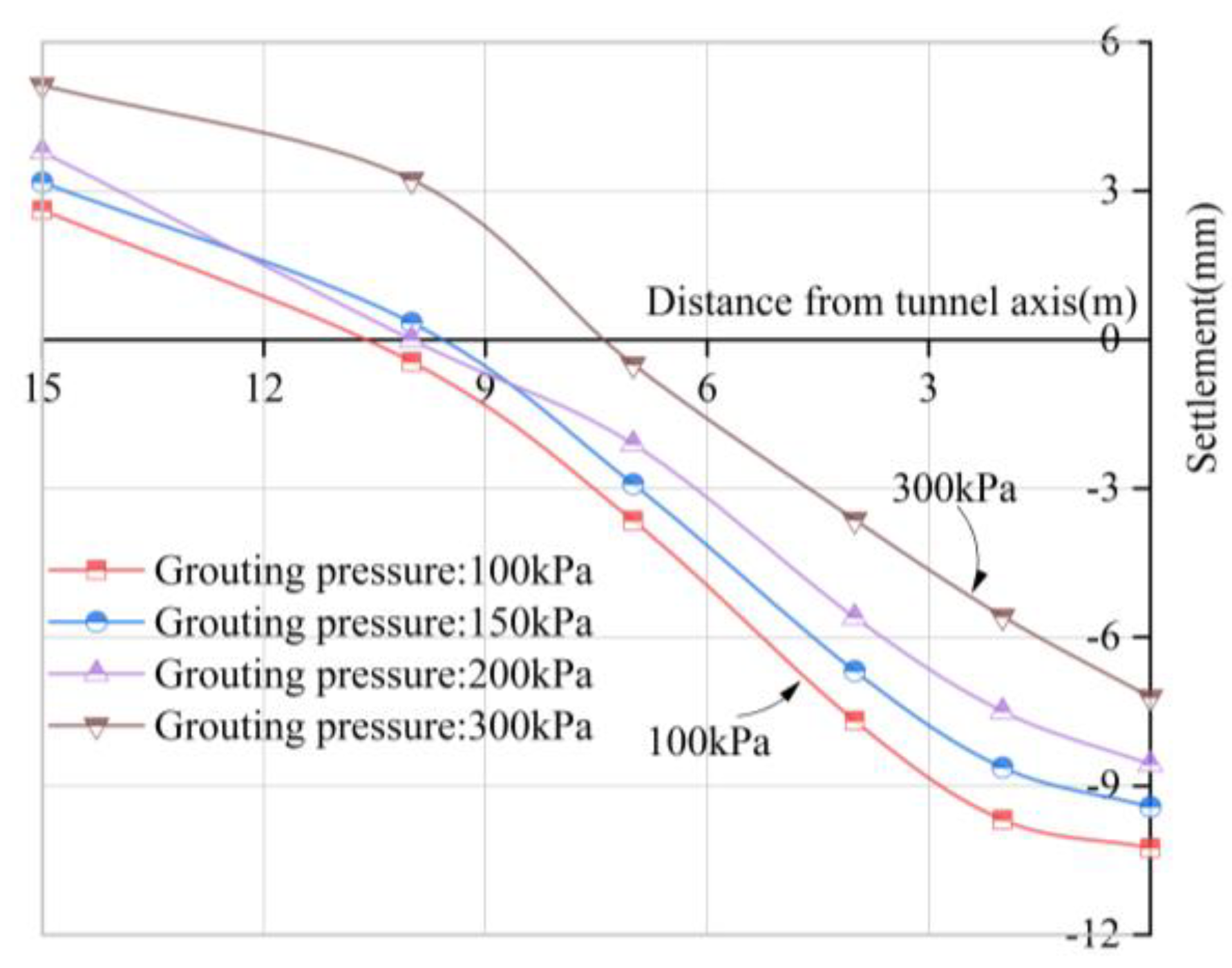
Influence of Grouting Pressure on the Lateral Deformation of Ground Surface

Figure 10 shows the influence of grouting pressure on surface settlement and deformation, it can be seen from the figure that the maximum settlement value of the surface is inversely proportional to the grouting pressure. With the increase of the grouting pressure, the maximum settlement value of the surface decreases continuously, which has a good effect on controlling the surface settlement. However, with the increase of grouting pressure, the maximum surface uplift continued to increase. The surface uplift will cause greater harm to the ground, so the grouting pressure cannot be blindly increased. Strict monitoring of the grouting pressure should be carried out during construction to control the surface uplift and settlement more accurately.

Influence of Linear Shrinkage Rate on the Lateral Deformation of Ground Surface

Figure 11 is the surface settlement and deformation curve under different stratum loss rates. With the increase of the linear shrinkage rate, the width of the transverse trough of the surface remains basically unchanged, and the maximum settlement value of the surface increases significantly, and the closer to the shield axis, the greater the surface settlement value. Although the linear shrinkage rate increased very little during the simulation process, only 1%, the maximum settlement value of the ground surface increased by nearly 2 mm. Therefore, attention should be paid to the stratum loss of large-diameter shield tunnels, and the research results of other shield tunneling projects should not be arbitrarily applied. This paper also analyzes that when the linear shrinkage rate is 0%, the ground surface presents obvious uplift, which once again shows the rationality of the shield machine designed to be tapered. On the one hand, it can reduce the environmental impact of tunnel construction, and on the other hand, it can reduce construction resistance and speed up construction efficiency.

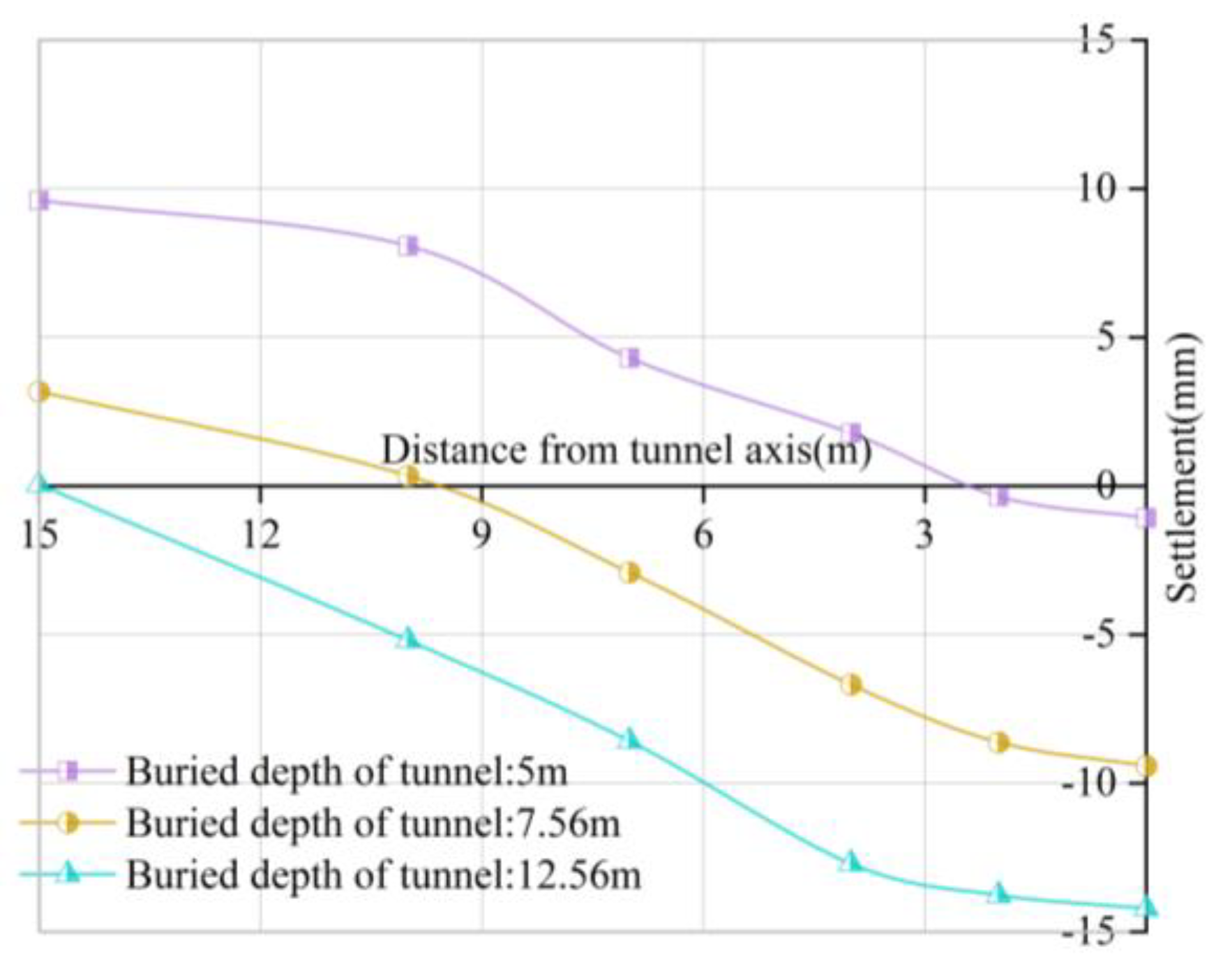
Influence of Buried Depth of Tunnel on the Lateral Deformation of Ground Surface

Figure 12 shows the influence of the buried depth of the tunnel on the lateral deformation of the ground surface. Existing studies believe [32] that in the condition of a certain excavation diameter of medium and small diameter tunnels, the surface settlement caused by tunnel construction is inversely proportional to the tunnel buried depth, that is, the greater the tunnel buried depth, the smaller the maximum surface settlement. However, it can be seen from Figure 12 that during the excavation of large-diameter shield tunnels, there is a linear relationship between surface settlement and tunnel buried depth, which is contrary to the research conclusions of medium and small diameter tunnels, and which is the same as the research conclusions of Wu (2018), Zhang et al. (2011) and others on large diameter shield tunnels [33,34]. The analysis shows that due to the large excavation section of the large-diameter shield, the buried depth required to form the soil arch effect in the stratum is large. When the buried depth of the tunnel is large but not enough to form the soil arch, the disturbance to the overlying soil increases, resulting in greater surface settlement; however, when the tunnel buried depth is small, under various comprehensive factors, the ground surface will be uplifted, which will offset the stratum loss, so that the surface settlement will be reduced instead.

Influence of Excavation Radius on the Lateral Deformation of Ground Surface

Under the condition of the same buried depth of the tunnel, the influence of the excavation radius R on the lateral deformation of the ground surface is analyzed, as shown in Figure 13. With the continuous increase of the shield excavation section, the maximum transverse value of the surface continues to increase. When the shield radius increases from 3 m to 5 m, the maximum settlement value increases by about 1.5 mm, and when the shield radius increases from 5 m to 6.5 m, the maximum settlement increases by about 3.5 mm. It can be speculated that if the grouting and support parameters are not adjusted in time, the surface deformation will increase sharply with the expansion of the shield radius. As well, it is found that with the increase of the tunnel excavation radius, the surface uplift is larger. When the shield radius R = 3 m, the surface uplift is very small, only 0.27 mm, the main reason is that with the increase of the excavation radius, the ratio of the thickness of the overlying soil to the excavation radius decreases, and the large-diameter shield has a large disturbance range to the overlying soil. Under the combined effects of grouting pressure and support pressure, the surface is uplifted.

4.5.2. Sensitivity Analysis of Surface Longitudinal Deformation Parameters

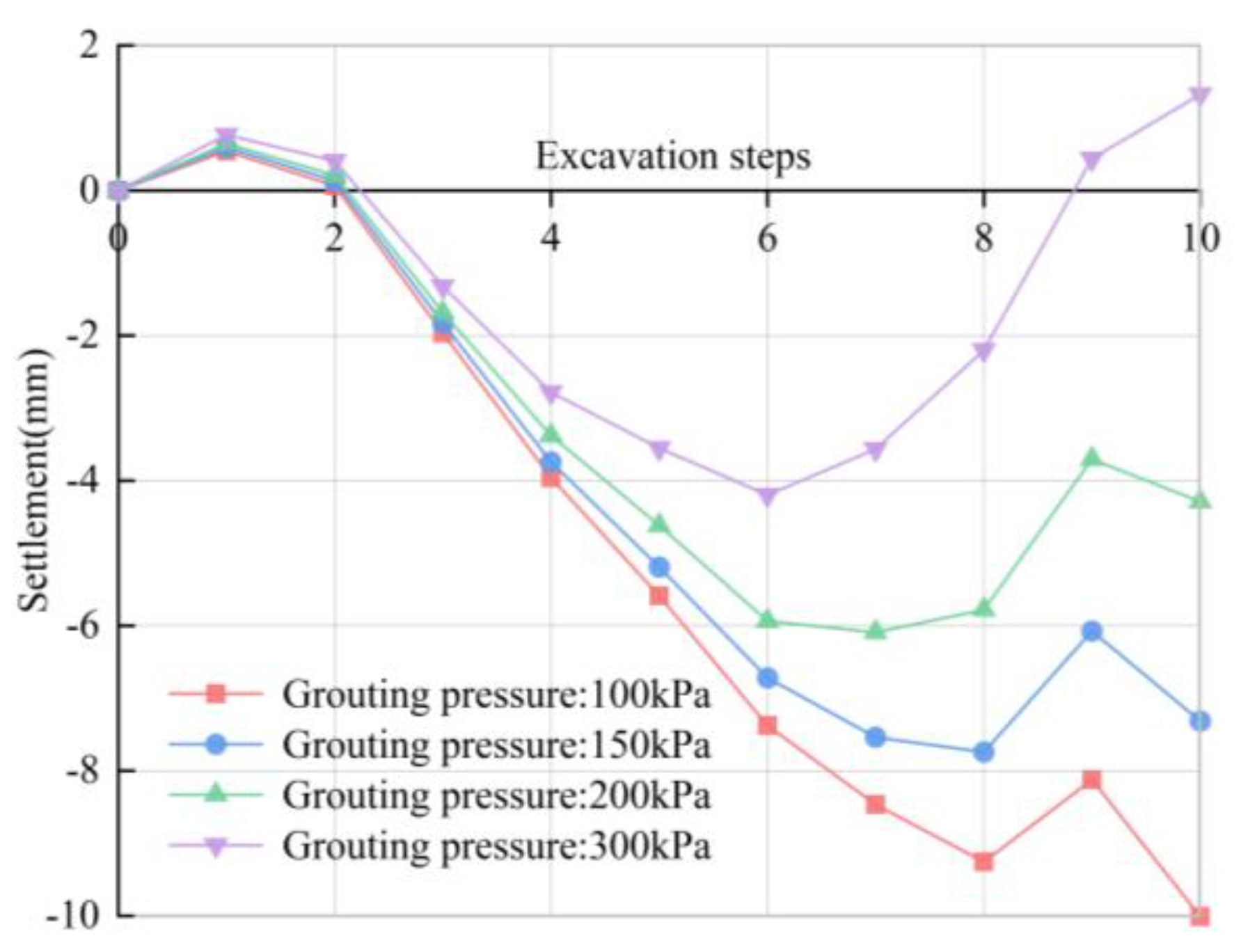
Influence of Grouting Pressure on the Longitudinal Deformation of Ground Surface

The influence of grouting pressure on the longitudinal deformation of the ground surface is shown in Figure 14. It can be seen from the figure that the longitudinal settlement of the ground surface decreases with the increase of the grouting pressure of the shield tail, and the decreasing rate is roughly the same. When the shield tail comes out of the monitoring section, the longitudinal settlement of the surface will rebound. The analysis shows that when the grouting pressure increases, the maximum principal stress of the overlying soil layer on the tunnel vault decreases, and the corresponding minimum principal stress increases, which reduces the soil settlement. When the grouting pressure is 300 kPa, it can be seen that there are obvious uplifts in the longitudinal direction of the surface. During the construction process, the monitoring of the grouting pressure of the shield tail should be strengthened to prevent construction disasters caused by excessive grouting pressure.

Influence of Linear Shrinkage Rate on the Longitudinal Deformation of Ground Surface

The influence of linear shrinkage rate on the longitudinal deformation of the ground surface is shown in Figure 15. It can be seen from the figure that the longitudinal settlement and deformation of the surface increases with the increase of the linear shrinkage rate, and the increased value is more obvious. The linear shrinkage rate of the body must be paid attention to when designing the shield machine. Synchronous grouting and secondary grouting should be carried out in time to reduce the influence of construction gaps caused by linear shrinkage rate on surface settlement. When the linear shrinkage rate is 0%, the friction between the shield machine and the surrounding soil increases, causing the ground surface to uplift. Therefore, in order to ensure the accuracy of the numerical simulation results, the linear shrinkage of the shield from the cutter head to the shield tail should be considered.

Influence of Excavation Radius on the Longitudinal Deformation of Ground Surface

Figure 16 shows the influence of tunnel excavation radius on the longitudinal deformation of the ground surface. It can be seen from the figure that the maximum surface settlement value increases with the increase of the tunnel excavation radius. The analysis shows that the larger the shield tunnel excavation radius, the stronger the disturbance to the soil layer, which increases the maximum settlement value of the ground surface. When the finite element simulation excavation reaches the eighth step, the shield tail just reaches the selected monitoring section, and when the finite element simulation excavation reaches the ninth ring, the shield tail comes out. At this time, due to the removal of the shield machine, the overlying pressure decreases sharply, the surface settlement decreases, and the soil settlement tends to be stable afterward.

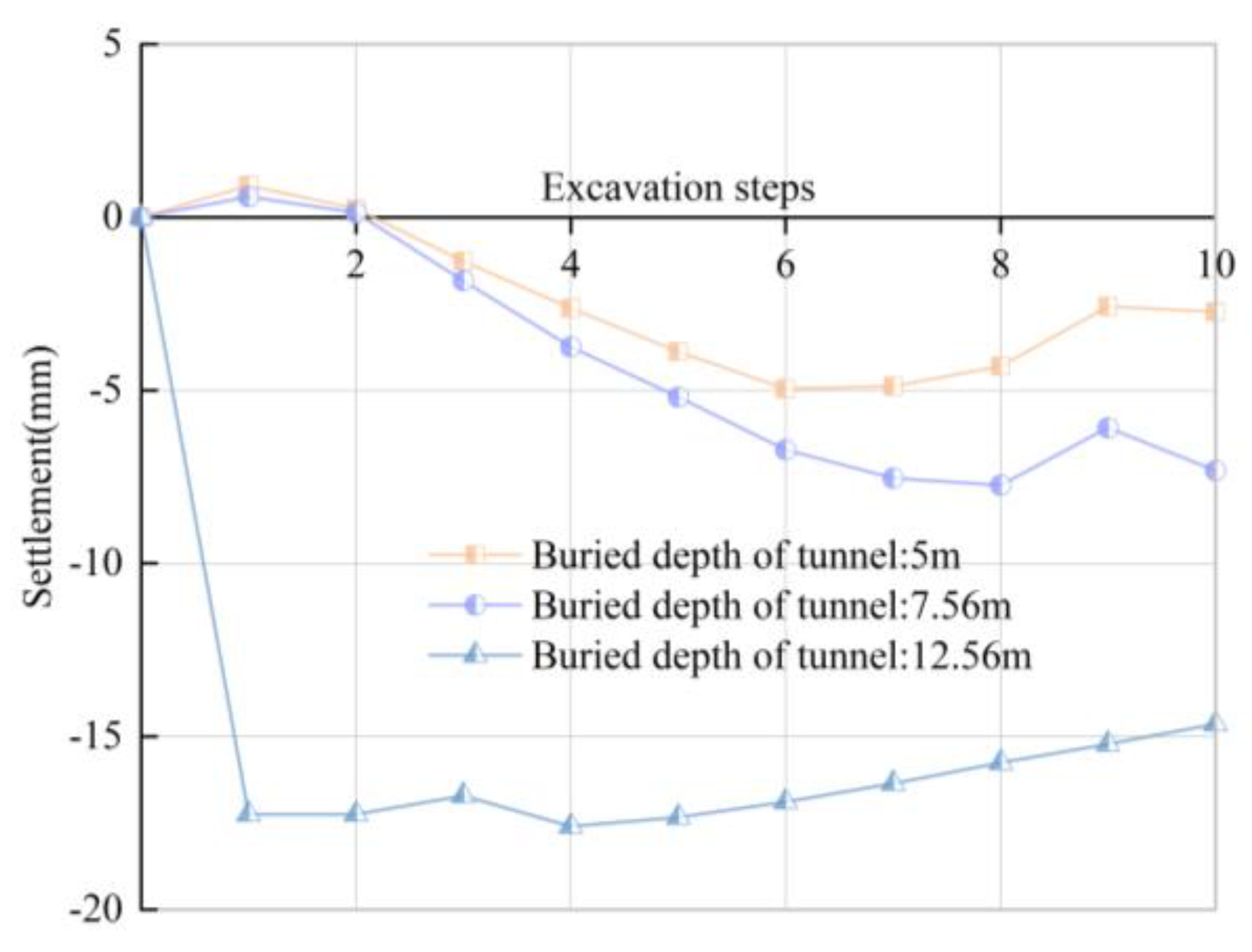
Influence of the Buried Depth of the Tunnel on the Longitudinal Deformation of Ground Surface

Figure 17 shows the influence of tunnel buried depth on the longitudinal deformation of the ground surface. It can be seen from the figure that the longitudinal settlement of the surface increases with the increase of the buried depth of the shield center. When the buried depth of the tunnel is 7.56 m and 5 m, the surface uplift phenomenon occurs, and the uplift value increases with the decrease of the buried depth. Therefore, the tunnel design needs to meet the requirements of the minimum covering soil thickness, otherwise, the support pressure of the excavation face and the grouting pressure of the shield tail may cause a large uplift value of the tunnel, which will endanger the safety of the tunnel. When the tunnel is buried at a depth of 12.56 m, there is basically no uplift on the surface. It can be seen that increasing the buried depth of the tunnel can be used as a means to reduce the surface uplift when designing the tunnel.

5. Conclusions

Through the statistical analysis of the on-site monitoring data and numerical simulation, the law of surface deformation caused by the excavation of the large-diameter slurry shield in the upper-soft lower-hard composite stratum under the condition of shallow overburden is studied. At the same time, the sensitivity analysis of the key construction parameters in the shield tunneling process was carried out, and the following research conclusions were obtained:
  • According to the on-site monitoring data, the surface settlement curve at the shield axis during the construction period can be divided into four stages: pre-deformation, shield passing, shield tail exit, and shield moving away. The proportion of soil settlement in each stage to total settlement is 5.39%, 64.58%, 15.84%, and 14.2% respectively.
  • Statistical values of on-site construction parameters can be used as an effective method for parameter setting of numerical simulation models, as the main factor affecting soil deformation during shield excavation, linear shrinkage rate should be considered in numerical analysis.
  • Support pressure and grouting pressure as important construction parameters of shield tunneling. The maximum settlement value of the ground surface at the center of the tunnel increases with the increase of the support pressure, when the support pressure exceeds 300 kPa, the surface uplift and the settlement caused by stratum loss are offset, and the surface settlement is reduced instead, the maximum settlement value of the surface is inversely proportional to the grouting pressure, but with the increase of the grouting pressure, the maximum surface uplift continues to increase.
  • With the numerical simulation of excavation step construction, the surface uplift increases with the increase of grouting pressure and shield radius, and decreases with the increase of shield buried depth.

Author Contributions

Conceptualization, Y.M.; Data curation, D.Z.; Formal analysis, D.Z.; Investigation, D.Z., Y.Z. (Yuhang Zhang) and Y.Z. (Yu Zhang). Methodology, Y.M.; Resources, W.S., Y.Z. (Yuhang Zhang) and Y.Z. (Yu Zhang); Supervision, Y.M.; Validation, D.Z.; Writing—original draft, D.Z. and W.S. Writing—review & editing, Y.M. and Y.Z. (Yu Zhang). All authors have read and agreed to the published version of the manuscript.

Funding

The research described in this paper was financially supported by the National Natural Science Foundation of China [Grant No. 52178302], and the Key R & D Projects in Shaanxi Province [No. 2020SF-373].

Institutional Review Board Statement

Not applicable.

Informed Consent Statement

Not applicable.

Data Availability Statement

Not applicable.

Conflicts of Interest

The authors declare that they have no known competing financial interest or personal relationships that could have appeared to influence the work reported in this paper.

References

  1. Mei, Y.; Zhou, D.; Wang, X.; Zhao, L.; Shen, J.; Zhang, S.; Liu, Y. Deformation Law of the Diaphragm Wall during Deep Foundation Pit Construction on Lake and Sea Soft Soil in the Yangtze River Delta. Adv. Civ. Eng. 2021, 2021, 6682921. [Google Scholar] [CrossRef]
  2. Wang, X.Y.; Ma, Z.; Zhang, Y.T. Research on Safety Early Warning Standard of Large-Scale Underground Utility Tunnel in Ground Fissure Active Period. Front. Earth Sci. 2022, 10, 828477. [Google Scholar] [CrossRef]
  3. Wang, X.; Gong, H.; Song, Q.; Yan, X.; Luo, Z. Risk Assessment of EPB Shield Construction Based on the Nonlinear FAHP Method. Adv. Civ. Eng. 2022, 2022, 9233833. [Google Scholar] [CrossRef]
  4. Yuan, B.; Li, Z.; Chen, W.; Zhao, J.; Lv, J.; Song, J.; Cao, X. Influence of Groundwater Depth on Pile—Soil Mechanical Properties and Fractal Characteristics under Cyclic Loading. Fractal Fract. 2022, 6, 198. [Google Scholar] [CrossRef]
  5. Jin, H.; Yu, K.; Gong, Q.; Zhou, S. Load-carrying capability of shield tunnel damaged by shield shell squeezing action during construction. Thin-Walled Struct. 2018, 132, 69–78. [Google Scholar] [CrossRef]
  6. Wang, X.; Song, Q.; Gong, H. Research on Deformation Law of Deep Foundation Pit of Station in Core Region of Saturated Soft Loess Based on Monitoring. Adv. Civ. Eng. 2022, 2022, 7848152. [Google Scholar] [CrossRef]
  7. Zheng, G.; Fan, Q.; Zhang, T.; Zhang, Q. Numerical study of the Soil-Tunnel and Tunnel-Tunnel interactions of EPBM overlapping tunnels constructed in soft ground. Tunn. Undergr. Space Technol. 2022, 124, 104490. [Google Scholar] [CrossRef]
  8. Xie, X.; Yang, Y.; Ji, M. Analysis of ground surface settlement induced by the construction of a large-diameter shield-driven tunnel in Shanghai, China. Tunn. Undergr. Space Technol. 2016, 51, 120–132. [Google Scholar] [CrossRef]
  9. Shi, C.; Cao, C.; Lei, M. An analysis of the ground deformation caused by shield tunnel construction combining an elastic half-space model and stochastic medium theory. KSCE J. Civ. Eng. 2016, 21, 1933–1944. [Google Scholar] [CrossRef]
  10. Cheng, H.; Chen, J.; Chen, G. Analysis of ground surface settlement induced by a large EPB shield tunnelling: A case study in Beijing, China. Environ. Earth Sci. 2019, 78, 605. [Google Scholar] [CrossRef]
  11. Wang, P.; Kong, X.; Guo, Z.; Hu, L. Prediction of Axis Attitude Deviation and Deviation Correction Method Based on Data Driven during Shield Tunneling. IEEE Access 2019, 7, 163487–163501. [Google Scholar] [CrossRef]
  12. Yuan, B.; Chen, M.; Chen, W.; Luo, Q.; Li, H. Effect of Pile-Soil Relative Stiffness on Deformation Characteristics of the Laterally Loaded Pile. Adv. Mater. Sci. Eng. 2022, 2022, 4913887. [Google Scholar] [CrossRef]
  13. Peck, R.B. Deep excavation sand tunneling in soft ground. In Proceedings of the 7th International Conference on Soil Mechanics and Foundation Engineering, Mexico City, Mexico, 25 August 1969; Volume 10, pp. 225–290. [Google Scholar]
  14. Attewell, P.B. Engineering Contract, Site investigation and Surface Movements in Tunnelling Works. In Soft-Ground Tunneling, Failures and Displacement. Panamerican Conference on Soil Mechanics and Foundation Engineering; A.A. Balkema: Rotterdam, The Netherlands, 1981; Volume 1, pp. 5–12. [Google Scholar]
  15. Mair, R.J.; Taylor, R.N.; Bracegirdle, A. Subsurface settlement profiles above tunnels in clays. Géotechnique 1993, 43, 315–320. [Google Scholar] [CrossRef]
  16. Mei, Y.; Song, Q. Analytical Solution for Settlement of Homogeneous Structure where the Tunnel Passes Underneath and Its Application. KSCE J. Civ. Eng. 2021, 25, 3556–3567. [Google Scholar] [CrossRef]
  17. Sagaseta, C. Analysis of undrained soil deformation due to ground loss. Geotechnique 1987, 37, 301–320. [Google Scholar] [CrossRef]
  18. Sagaseta, C. Discussion: Analysis of undrained soil deformation due to ground loss. Geotechnique 1988, 38, 647–649. [Google Scholar] [CrossRef]
  19. Loganathan, N.; Poulos, H.G. Analytical Prediction for Tunneling-Induced Ground Movements in Clays. J. Geotech. Geoenviron. Eng. 1998, 124, 846–856. [Google Scholar] [CrossRef]
  20. Lin, Q.; Lu, D.; Lei, C.; Tian, Y.; Gong, Q.; Du, X. Model test study on the stability of cobble strata during shield under-crossing. Tunn. Undergr. Space Technol. 2021, 110, 103807. [Google Scholar] [CrossRef]
  21. Cheng, Q.X.; Lu, A.Z.; Yin, C.L. Analytical Stress Solutions for a Deep Buried Circular Tunnel under an Unsteady Temperature Field. Rock Mech. Rock Eng. 2021, 54, 1355–1368. [Google Scholar] [CrossRef]
  22. Zheng, G.; Yang, X.; Zhou, H.; Du, Y.; Sun, J.; Yu, X. A simplified prediction method for evaluating tunnel displacement induced by laterally adjacent excavation. Comput. Geotech. 2018, 95, 119–128. [Google Scholar] [CrossRef]
  23. Lu, P.; Yuan, D.; Chen, J.; Jin, D.; Wu, J.; Luo, W. Face Stability Analysis of Slurry Shield Tunnels in Rock-Soil Interface Mixed Ground. KSCE J. Civ. Eng. 2021, 25, 2250–2260. [Google Scholar] [CrossRef]
  24. Pan, H.; Tong, L.; Wang, Z.; Yang, T. Effects of Soil—Cement Mixing Wall Construction on Adjacent Shield Tunnel Linings in Soft Soil. Arab. J. Sci. Eng. 2022, 1–15. [Google Scholar] [CrossRef]
  25. Zhang, D.-M.; Liu, Z.-S.; Wang, R.-L. Influence of grouting on rehabilitation of an over-deformed operating shield tunnel lining in soft clay. Acta Geotech. 2018, 14, 1227–1247. [Google Scholar] [CrossRef]
  26. Qi, W.; Yang, Z.; Jiang, Y.; Shao, X.; Yang, X.; He, Q. Structural Deformation of Existing Horseshoe-Shaped Tunnels by Shield Overcrossing. KSCE J. Civ. Eng. 2020, 25, 735–749. [Google Scholar] [CrossRef]
  27. Zhang, J.; Huang, L.; Peng, T.; Wang, H.; Zhang, Y.; Guo, L. Model Testing on Failure Mechanism of Tunnel Face in Sandy Cobble Stratum. Arab. J. Sci. Eng. 2020, 45, 4077–4089. [Google Scholar] [CrossRef]
  28. Dai, X.; Cai, J.; Diao, Y.; Huo, H.; Xu, G. Influence of tunnelling on the deformation of the overlying excavation bracing system and analysis of countermeasures. Comput. Geotech. 2021, 134, 104089. [Google Scholar] [CrossRef]
  29. Li, S.; Zhang, Y.; Cao, M.; Wang, Z. Study on Excavation Sequence of Pilot Tunnels for a Rectangular Tunnel Using Numerical Simulation and Field Monitoring Method. Rock Mech. Rock Eng. 2022, 55, 3507–3523. [Google Scholar] [CrossRef]
  30. Yuan, B.; Chen, W.; Zhao, J.; Yang, F.; Luo, Q.; Chen, T. The Effect of Organic and Inorganic Modifiers on the Physical Properties of Granite Residual Soil. Adv. Mater. Sci. Eng. 2022, 2022, 9542258. [Google Scholar] [CrossRef]
  31. Lee, H.; Choi, H.; Choi, S.-W.; Chang, S.-H.; Kang, T.-H.; Lee, C. Numerical Simulation of EPB Shield Tunnelling with TBM Operational Condition Control Using Coupled DEM-FDM. Appl. Sci. 2021, 11, 2551. [Google Scholar] [CrossRef]
  32. Qian, J.-G.; Li, W.-Y.; Yin, Z.-Y.; Yang, Y. Influences of buried depth and grain size distribution on seepage erosion in granular soils around tunnel by coupled CFD-DEM approach. Transp. Geotech. 2021, 29, 100574. [Google Scholar] [CrossRef]
  33. Wu, C.S. Study on the Ground Deformation Induced by Large Diameter Shield Tunnelling Construction. Ph.D. Thesis, School of Transportation Southeast University, Nanjing, China, October 2018. (In Chinese). [Google Scholar]
  34. Zhang, Z.M.; Lin, C.G.; Wu, S.M.; Liu, G.S.; Wang, C.S.; Xie, W.B. Analysis and control of ground settlement of embankments in construction of cross-river shield tunnels. Chin. J. Geotech. 2011, 33, 977–984. (In Chinese) [Google Scholar]
Figure 1. Overview of the shield test section; (a) Tunnel design effect diagram; (b) Tunnel excavation geology and roadside diagram; (c) Measuring point layout diagram; (d) Measuring point burying and monitoring construction diagram.
Buildings 12 01470 g001
Figure 2. Surface settlement monitoring curve (a) Surface settlement duration curve of the axis at ring 3; (b) Surface settlement duration curve of the axis at ring 75; (c) Surface settlement duration curve of the axis at ring 80.
Buildings 12 01470 g002
Figure 3. Percentage of settlement composition at each stage.
Buildings 12 01470 g003
Figure 4. Lateral surface settlement trough caused by tunnel excavation.
Buildings 12 01470 g004
Figure 5. Tunnel construction and excavation parameters (a) support pressure, (b) shield thrust.
Buildings 12 01470 g005
Figure 6. Three-dimensional finite element analysis model of the tunnel.
Buildings 12 01470 g006
Figure 7. Comparison of monitoring data and numerical model surface transverse curve.
Buildings 12 01470 g007
Figure 8. Influence of shield thrust on the lateral deformation of the ground surface.
Buildings 12 01470 g008
Figure 9. Influence of support pressure on the lateral deformation of the ground surface.
Buildings 12 01470 g009
Figure 10. Influence of grouting pressure on the lateral deformation of the ground surface.
Buildings 12 01470 g010
Figure 11. Influence of linear shrinkage rate on the lateral deformation of the ground surface.
Buildings 12 01470 g011
Figure 12. Influence of buried depth of tunnel on the lateral deformation of the ground surface.
Buildings 12 01470 g012
Figure 13. Influence of excavation radius on the lateral deformation of the ground surface.
Buildings 12 01470 g013
Figure 14. Influence of grouting pressure on the longitudinal deformation of the ground surface.
Buildings 12 01470 g014
Figure 15. Influence of linear shrinkage rate on the longitudinal deformation of the ground surface.
Buildings 12 01470 g015
Figure 16. Influence of excavation radius on the longitudinal deformation of the ground surface.
Buildings 12 01470 g016
Figure 17. Influence of the buried depth of the tunnel on the longitudinal deformation of the ground surface.
Buildings 12 01470 g017
Table 1. Tunnel excavation condition setting.
PhaseShield PositionMain Simulation Content
0initial stepgeo-stress balance, generated stress field
1the shield machine is located at y = 46 mstratum loss in an initial state; grouting pressure at shield tail; excavation face support pressure
2the shield machine is located at y = 48 mstratum loss; grouting pressure at shield tail; excavation face support pressure; shield forward thrust
10the shield machine is located at y = 62 mstratum loss; grouting pressure at shield tail; excavation face support pressure; shield forward thrust
Table 2. Soil layer distribution and soil physical and mechanical parameters.
Soil HorizonThickness/mγ/(kN/m3)c’ (kPa)φ’/°E/MPaK0v
crushed stone fill1.017.0103040autonomous0.30
miscellaneous fill1.418.0203525autonomous0.30
silt clay3.318.5203035autonomous0.25
silty clay3.717.5203535autonomous0.25
crushed stone with cohesive soil5.619.0203030autonomous0.20
fully weathered siltstone9.818.0405035autonomous0.20
strongly weathered siltstone15.219.0405040autonomous0.25
moderately weathered siltstone20.021.520040500autonomous0.20
Note: γ: Soil mass weight; c’: Effective cohesion of soil; φ’: Effective internal friction angle of soil; E: Young’s modulus of soil; v: Poisson’s ratio.
Publisher’s Note: MDPI stays neutral with regard to jurisdictional claims in published maps and institutional affiliations.

