

Masonry Elements Strengthened with TRM: A Review of Experimental, Design and Numerical Methods

Department of Concrete and Masonry Structures, Faculty of Civil Engineering, Czech Technical University, Thákurova 7, 166 29 Praha 6, Czech Republic
Buildings 2022, 12(9), 1307; https://doi.org/10.3390/buildings12091307
Submission received: 4 August 2022
/
Revised: 18 August 2022
/
Accepted: 23 August 2022
/
Published: 25 August 2022
(This article belongs to the Special Issue Advances in Modelling and Testing the Performance of Masonry Structures)
Abstract
:Textile-Reinforced Mortar (TRM) is a modern and compatible strengthening strategy for existing masonry, which consists in plastering the walls by means of mortar layers with embedded grids or textiles made of long fibers. TRM can be very useful for the reduction of the seismic vulnerability of masonry buildings, since the fiber-based reinforcement, carrying high tensile stresses, opposes the widening of cracks and provides “pseudo-ductility” to the masonry. The increasing number of available studies on the subject testifies to its relevance but also the lack of a standardized or well-establish approach to quantify the benefits of these systems on the performance of masonry. The present review is aimed at providing a broad overview of how the study of TRM-strengthened masonry elements has been addressed in the literature. In particular, the main features of the different experimental tests are compared, dealing with both in-plane and out-of-plane behavior. Moreover, the different design methods and numerical modeling strategies are presented and discussed.
1. Introduction
Textile-Reinforced Mortar (TRM) is a modern and compatible strengthening strategy for the seismic protection of existing masonry buildings. It consists of plastering the walls by means of mortar layers with embedded grids of textiles made of long fibers (e.g., glass, carbon and basalt). The well-known advantages are related to the coupling of an un-corrosive reinforcement, having a high strength-to-weight ratio, to an easy-to-install inorganic matrix, which has good mechanical and chemical compatibility with historical masonry (bond to rough surface and breathability) and provides UV-ray and fire resistance. Different combinations of matrix and reinforcement reflect in different TRM composite materials, which may be called, e.g., FRM (fabric reinforced mortar), FRCM (fiber-reinforced cementitious matrix/mortar), TRC (textile reinforced concrete), IMG (inorganic matrix-grid composites) and CRM (composite reinforced mortar).
The systematic study of the TRM effectiveness implies a series of tests of increasing complexity, ranging from single components to entire masonry structures strengthened with TRM. Recently, the author performed a broad literature analysis on TRM at the characterization test level [1], evidencing the great variety of features that deserve attention, related to the multitude of possible materials combinations as well as to their mutual interaction and with the masonry support. The benefits of TRM basically rely on the high tensile resistant capability of the fibers, which can be fully exploited or limited by the textile slippage within the matrix or by the debonding of the matrix from the masonry substrate.
As a continuation of the literature review, this paper focuses on the review of studies investigating the structural performances of TRM-strengthened masonry elements subjected to lateral loads, dealing with experimental approaches, design methods and numerical modeling strategies. In fact, what is typically found in available literature surveys concerns insights into a specific task (e.g., a specific experimental setup to be tested or simulated or a specific failure mechanism to be designed). Furthermore, they are mainly focused on comparing the effectiveness of different TRM reinforcements rather than comparing the characteristics of the different investigative methods. Differently, the purpose of this manuscript is to provide a comprehensive overview of the topic, commenting on all the typical setups adopted for evaluating the role of TRM in the different resisting mechanisms of masonry elements and gathering together experimental, practice design and numerical aspects.
2. Experimental Tests
On-site surveys after seismic events [4,5,6,7] let the identification of recurrent damage modes affecting historic, unstrengthened masonry buildings. The lack of effective connection between floors and walls and/or between adjacent walls and the presence of pushing elements are typical defects. In addition, very weak masonry (made of poor mortar, rambling units and disjointed layers) is affected by disaggregation or leaf separation phenomena. The seismic response of masonry buildings devoid of these shortcomings is mainly governed by the in-plane and out-of-plane wall response, as discussed in the following subsections. Many suggestive pictures, in the mentioned references, testify to the real occurrence of the walls’ in-plane and out-of-plane failure mechanisms discussed later on.
However, the experimental study of the actual behavior of entire masonry structures under seismic actions is complex and burdensome. Thus, it is generally addressed in a simplified way, evaluating the effects induced by equivalent transversal quasi-static actions acting in the plane or out of the plane of isolated masonry samples. The TRM contribution and its influence on the masonry failure modes are achieved by comparing the performances of unstrengthened and strengthened samples. In general, it is concluded that the benefits of the TRM application rely on its capability to dissipate energy through multi-cracking patterns: the textile, carrying tensile stresses, opposes the widening of cracks and provides “pseudo-ductility” to the masonry, preserving some integrity after damage [8,9,10]. The extent of these benefits is influenced by the loading conditions, as well as by the characteristics of both the reinforcement and the masonry, but can be compromised, e.g., by debonding or crushing.
In the following, the typical setups adopted for testing experimentally TRM-strengthened masonry elements have been compared and discussed. In particular, when testing under in-plane actions, they are distinguished between simplified tests (such as the diagonal compression tests and the three-point bending tests) and full-scale cyclic tests on masonry piers and on masonry spandrels. The setups for out-of-plane testing can basically be differentiated for the load distribution and trend.
2.1. In-Plane Loading
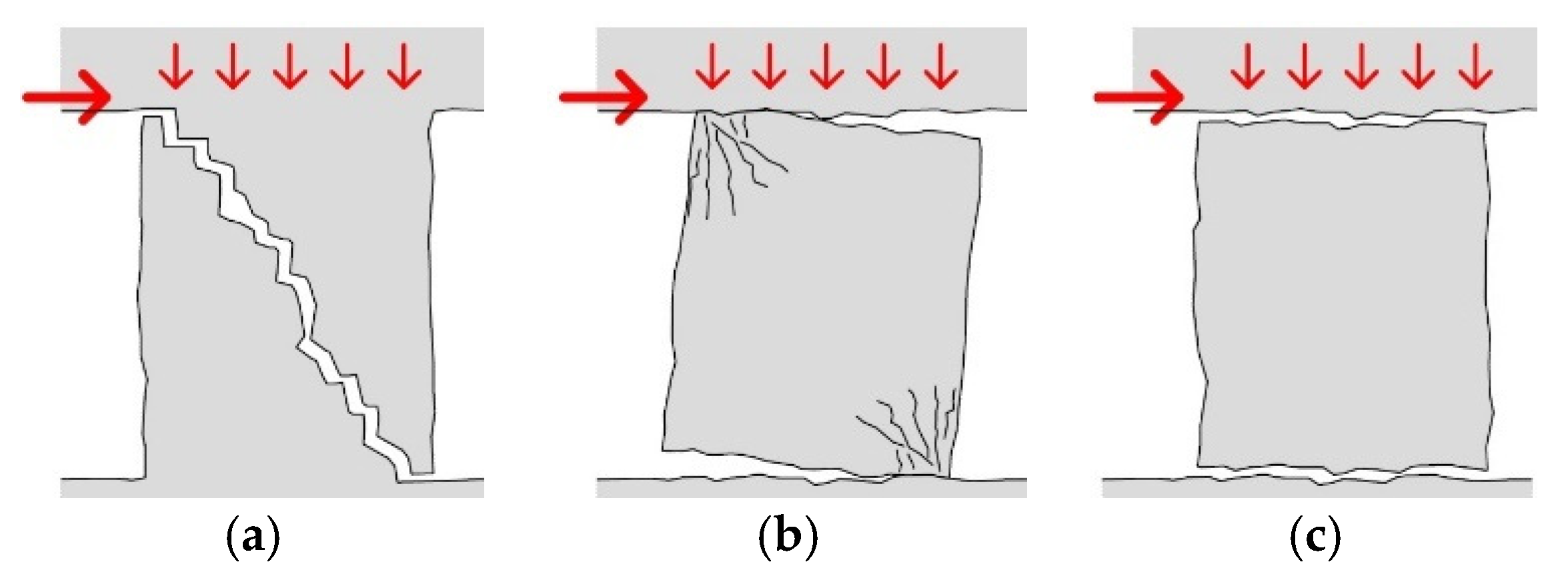
Referring to in-plane lateral loads, it is well known that the failure of a workmanlike built masonry element (i.e., a pier or a spandrel) may be due to diagonal cracking, bending (rocking or toe crushing) or shear sliding—Figure 1—depending on the wall slenderness, axial stress level and boundary conditions, as evidenced in several experimental testing campaigns available in the literature, for both piers [11,12,13] and spandrels [14,15,16]. Shear-dominated response exhibited diagonal cracking and a load-drift response characterized by high energy dissipation but by rather rapid strength degradation. In the flexure-dominated response, the damage is typically concentrated at the wall ends; it is characterized by a very moderate hysteretic energy dissipation and rather smooth strength degradation. Sliding typically occurs together with rocking when low axial loads are present.
The TRM application can change the resistance, the displacement capacities, the energy dissipation, the damage pattern and the failure mode with respect to plain masonry; its effectiveness can vary depending on the governing failure mechanism, as well as on the varying characteristics of the masonry.
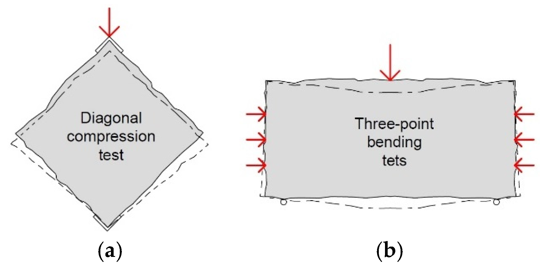
The experimental tests available in the literature investigating the in-plane performances of TRM-strengthened masonry mainly concern simplified diagonal compression tests (Figure 2a) due to the relatively easy procedure (Table 1); however, as pointed out, for example, in [17,18,19], this kind of test can provide information related to the diagonal cracking failure mechanism only. The test consists of a square masonry panel (side 0.9–1.2 m, typically) loaded in compression along one diagonal, by using stiff loading shoes [20,21]. The loaded diagonal is arranged in the vertical direction, even though sometimes, the horizontal orientation of the bed joints is preferred, to avoid sample handling [22,23,24,25,26,27,28], as for in situ tests [18,29,30]. The standard test is based on monotonic loading, but loading–unloading steps are also performed to obtain useful information on energy dissipation and cumulative damage [17,18,22,24,25,28,30,31]. The results are compared in terms of diagonal load at the varying displacements (or strains) along the panel diagonals, monitored along almost their whole length or, occasionally, focusing on a more restricted central portion [8,23,27,32,33,34]. The results can also be reported in terms of calculated shear stress at the varying shear strain, but these outcomes are affected by the different interpretations given to the tests and, in particular, to the assumed stress state at the panel center, which is still an open issue, as evidenced by several authors [28,32,35,36,37].
Most of the diagonal-compression experimental tests available in the literature on TRM-strengthened masonry focused on a single leaf, clay solid brick masonry; however, some authors tested also panels made of tuff [8,23,27,32,33,38], hollow bricks [17], stones [18,24,25,30] and multiple leaves or infill clay brick masonry [19,24,26,29]. The tested TRM reinforcements mainly concerned glass fibers, but also carbon fibers [17,22], basalt fibers [26,33,34,36], natural fibers [10,23] and polymers [31,39]. The mortar matrix was usually cement-based and was applied in the form of a thin layer (about 5–15 mm thickness); however, thicker layers (range 20–40 mm) made of lime-based compounds were also investigated [17,19,22,23,24,25,27,28,30,31,35,38,39]. The mortar compressive strength generally ranged between 5 and 25 MPa; rarely, weaker [29] or stronger mixtures [17,36] were considered. The TRM layer is typically applied at both the wall faces; however, some authors also tested one-side application [8,27,32,33,34,40].
It was generally observed that, while unstrengthened specimens exhibited failure due to a single (or a few) wide diagonal crack (ranging from stair-stepped to linear trends, depending on the regularity of the texture and on the resistance of the block), the TRM-strengthened samples experienced several smaller cracks on the plaster and a subsequent gradual rupture of the fibers as these cracks opened, allowing a progressive resistance decrease after the attainment of the peak load. The embedded fiber-based reinforcement revealed thus fundamental in improving the deformation capacity of the masonry sample, as also evidenced by comparison with panels provided with bare plaster only, which did not show any significant improvement in the ultimate distortion [31,39]. The TRM effectiveness also emerged when testing masonry panels damaged and then retrofitted, e.g., [27]. Multiple-ply applications can provide additional improvements [10,22,32,36]; however, high reinforcement ratios may anticipate failures, mostly related to the delamination of the TRM layer from the masonry or the crushing of the masonry in the loading corners [17,41]. Actually, the bond between the mortar matrix and the masonry substrate was found as a key aspect of the TRM effectiveness, since the introduced additional stiffness may generate high shear stresses at the interface level; therefore, in many cases, the TRM layer was provided with mechanical anchors (e.g., helical steel bars [19,29,38] or resin-impregnated fiber-based anchors [23,24,25,27,30]) to improve the connection with the masonry and, besides, to induce some confinement within the masonry; however, diagonal compression tests do not allow to clearly highlight the role of anchors in actual applications, especially in symmetrically strengthened specimens, in which, often, no significant differences emerged in respect to configurations without mechanical anchorages [8,24,25,30]. Some anchor benefits were noted in one side strengthened samples, where parasitic out-of-plane bending emerged due to the stiffness un-symmetry, and the ties allowed the panel to attain higher strength and ductility [32,33,34,41]; however, these outcomes, as mentioned, can just provide a qualitative indication on the anchorage contribution under the actual stress state of masonry elements, as diagonal compression test is not suitable for this purpose.
Besides the wide investigations on the diagonal cracking failure mechanism, a few researchers also proved that TRM systems can be effective against in-plane bending failure. Papanicolaou et al. [42,43] performed simplified three-point bending tests considering the presence of a constant axial force and monitored the applied cyclic load at the varying mid-span deflection (Figure 2b). A flexural mid-crack emerged in the tests but then, higher resistance and deflection were attained, as the reinforcement was opposed to free rocking; a combined failure due to TRM debonding on the tensed side and hollow bricks crushing on the compressed side occurred. Boem and Gattesco [44] performed similar tests on solid brick masonry, following a loading–unloading procedure; the strengthened samples did not experience any debonding or crushing phenomena and the cracks spread in a wider area until the tensile failure of the fiber mesh.
Generally, no significant improvements due to the TRM application are expected for walls subjected to axial compression, as evidenced, e.g., by Donnini et al. [38]; the installation of mechanical anchors, adequately stiff and resistant, is necessary for such a purpose [45,46]. In fact, the transversal strains perpendicular to the wall, induced by the axial loading, cannot be effectively counteracted just by a near-surface application, especially in multiple-leaf masonry. Moreover, high stiffness mortar matrices, with respect to the masonry, may induce a concentration of shear stresses at the interface and activate the debonding.

Table 1.
Summary of simplified experimental tests on masonry samples.
| Reference | Masonry Type | Sample dim. TxB [mm] | Sample Orientation | TRM Side | Mortar fc 1 [MPa] | Thick [mm] | Embedded Grid | Load Scheme | Base Length [mm] | ||
|---|---|---|---|---|---|---|---|---|---|---|---|
| Diagonal compression tests | |||||||||||
| Parisi et al., 2013 [8] | Tuff solid blocks | 310 | 1230 | 45° | 1/2 | 16 | 10 | Glass | Monotonic | 400 | |
| Ferrara et al., 2020 [10] | Clay solid bricks | 120 | 1030 | 45° | 2 | 11 | 5, 8 | Flax | Monotonic | 1000 | |
| Almeida et al., 2015 [17] | Clay hollow bricks | 140 | 990 | 45° | 2 | 44 | 25 | Carbon | Monotonic/Load–unload | 700 | |
| Borri et al., 2011 [18] | Rubble stone | 670 | 1200 | 0° 2 | 2 | 11 | 30 | Glass | Load–unload | 1000 | |
| D’Antino et al., 2019 [19] | Clay solid bricks | 270 315 | 830 1000 | 45° | 2 | 7.5 | 20 | Glass | Monotonic | 620–800 | |
| Babaeidarabad et al., 2014 [22] | Clay solid bricks | 92 | 1200 | 0° | 2 | 24 | 10, 25 | Carbon | Load–unload | ||
| Menna et al., 2015 [23] | Tuff/Clay solid bricks | 250 | 1200 | 0° | 2 | 14, 16 | 15, 40 | Hemp | Monotonic | 400 | |
| Gattesco et al., 2015 [24] | Clay solid bricks Infill Rubble stone | 250/380 380 400 | 1160 | 0° | 2 | 7 | 30 | Glass | Load–unload | 1200 | |
| Gattesco and Boem, 2015 [25] | Clay solid bricks Rubble/Cobblestone | 250 400 | 1160 | 0° | 2 | 4–12 | 30 | Glass | Load–unload | 1200 | |
| Garcia-Ramonda et al., 2020 [26] | Clay solid bricks | 310 | 1270 | 0° | 2 | 14 | 10 | Basalt | Monotonic | 900 | |
| Del Zoppo et al., 2019 [27] | Tuff solid blocks | 250 | 1200 | 0° | 1/2 | 14 | 40 | Glass | Monotonic | 400 | |
| Borri et al., 2016 [28] | Clay solid bricks | 250 | 1160 | 0° | 2 | 0.7–2.7 | 50 | Glass | Load–unload | 1200 | |
| Carozzi et al.., 2018 [29] | Clay solid bricks | 300 | 1000 | 0° 2 | 2 | 7.5 | 10 | Glass | Monotonic | 850 | |
| Angiolilli et al., 2021 [30] | Rubble stone | 540 | 1200 | 0° 2 | 2 | 15 | 25 | Glass | Load–unload | 900 | |
| D’Ambrisi et al., 2013 [31] | Clay solid bricks | 260 | 1200 | 45° | 2 | 7 | 20 | Polymer | Load–unload | 1150 | |
| Prota et al., 2006 [32] | Tuff solid blocks | 250 | 1030 | 45° | 1/2 | 24 | 10 | Glass | Monotonic | 400 | |
| Marcari et al., 2017 [33] | Tuff solid blocks | 250 | 1000 | 45° | 1/2 | 9 | 8 | Basalt | Monotonic | 500 | |
| Basili et al., 20219 [34] | Clay solid bricks | 250 | 960 | 45° | 1/2 | 9 | 5 | Basalt | Monotonic | 500 | |
| Benedetti, 2019 [35] | Clay solid bricks | 118 | 1160 | 45° | 2 | 7.4–16 | 12, 15, 30 | Glass | Monotonic | 1200 | |
| Wang et al., 2019 [36] | Clay solid bricks | 110 | 900 | 45° | 2 | ~35/40 | 15 | Basalt | Monotonic | 1030 | |
| Donnini et al., 2021 [38] | Tuff/Clay solid bricks | 250 | 1200 | 45° | 2 | 8.4 | 30 | Glass | Monotonic | 1000 | |
| Oskouei et al., 2018 [39] | Clay solid bricks | 100 | 600 | 45° | 2 | - | 20 | Glass/Polymer | Monotonic | - | |
| Yardim e Lalaj. 2016 [40] | Clay solid bricks | 250 | 650 | 45° | 1/2 | 22 | 8 | Glass | Monotonic | - | |
| Casacci et al., 2019 [41] | Clay solid bricks | 100 | 530 | 45° | 1/2 | 7 | 10 | Glass | Monotonic | 500 | |
| Reference | Masonry type | Sample dim. TxWxL [mm] | Bed-joints Orientation 3 | TRM Side | Mortar fc 1 [MPa] | Thick [mm] | Embedded Grid | Load Scheme | Axial Stress [MPa] | ||
| In-plane bending tests | |||||||||||
| Papanicolaou et al., 2007–11 [41,42] | Clay hollow bricks | 85 | 400 | 1300 | V H | 2 | 31 | 4–6 | Carbon | Cyclic | 0.2, 0.5 0 |
| Boem and Gattesco, 2021 [44] | Clay solid bricks | 250 | 380 | 840 | V | 2 | 7 | 30 | Glass | Load–unload | 0, 0.15, 0.3 |
1 Compressive strength of the mortar coating, 2 In situ tests, 3 V = vertical bed-joints orientation, H = horizontal bed-joints orientation.
Even though it is useful to recognize, with rather simple testing procedures, the role of TRM in the different resisting mechanisms, simplified diagonal compression and three-point bending tests on masonry samples do not represent the behavior of an actual resisting element in a building. Thus, to recreate with more accuracy the actual stress state of the masonry piers in a building, shear-compression tests on full-scale elements were performed by applying a vertical load at the top of the panel, kept constant (representing the carried gravity loads) and then horizontal loading cycles (representing the seismic action). It is thus possible to identify more realistically the failure mechanism and the resistant and dissipative capacities of the masonry element, with respect to the simplified tests, but strictly in relation to the boundary conditions, geometry and axial stress level.
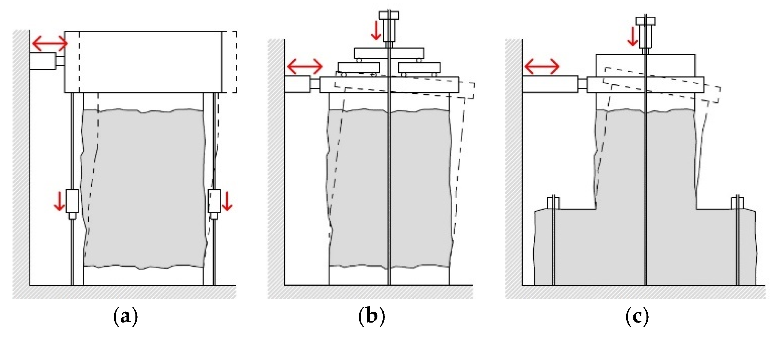
In some of the available tests (Table 2), the shear-type scheme was reproduced (Figure 3a), avoiding rotations at the panel top [31,47,48,49,50] and recreating, in such a way, the typical boundary condition of piers in a building with strong spandrels [51]. In contrast, a cantilever scheme (Figure 3b), which allows free rotation at the top [42,43,52,53,54,55,56,57], is representative of buildings with weak spandrels. The shear-compression tests available in the literature on TRM-strengthened panels typical concern samples having widths generally ranging from 800 to 3000 mm, with slender ratios from 0.68 to 1.6; the axial stress level is usually in the range 2.5%–10% of the masonry compressive stress or, in some cases, higher (e.g., 20%–30% [47,53,54]). The results were resumed in terms of applied horizontal load at the varying top horizontal displacement (or drift). The TRM application was proved to be effective also as retrofitting solution for damaged piers [49,52,53,54,57].
In the tests with the shear-type scheme, the diagonal cracking failure typically activated and the role of the embedded reinforcement in widespread cracks and dissipating energy clearly emerged also from comparison with samples strengthened with bare plaster [31,48]. Local debonding phenomena sometimes emerged at the mortar–masonry interface, induced by the compressive stress concentration at the corners, accompanied by the masonry crushing [48,52]. In the samples with high axial stress levels, the debonding was even more diffuse all over the wall and compromised the TRM collaboration with the masonry, evidencing the necessity of more resistant anchors to contrast this occurrence. The vertical cantilever scheme often evidenced a bending failure mode associated with the toe crushing without relevant diagonal cracks [42,43,57]; these tests also pointed out the importance of proper anchoring of the TRM layers at the wall extremities to obtain benefits against the bending mechanism with rocking. In this regard, it is worth mentioning the “reversed-T” testing procedure adopted by Messali et al. [57] (Figure 3c): the free rotation at the top was permitted, according to the zero-moment condition which occurs approximately at the half-height of piers under the shear-type scheme. The tests allowed us to more realistically investigate the diffusive flexural damage at the edge of the pier and clearly evidenced the role of the embedded reinforcement in contrast to rocking, carrying tensile strength. To counteract the bending effect due to the free rotation at the top, Guerreiro et al. [50] also reduced the height of the horizontal load, so to investigate the behavior of piers dominated by the shear contribution.
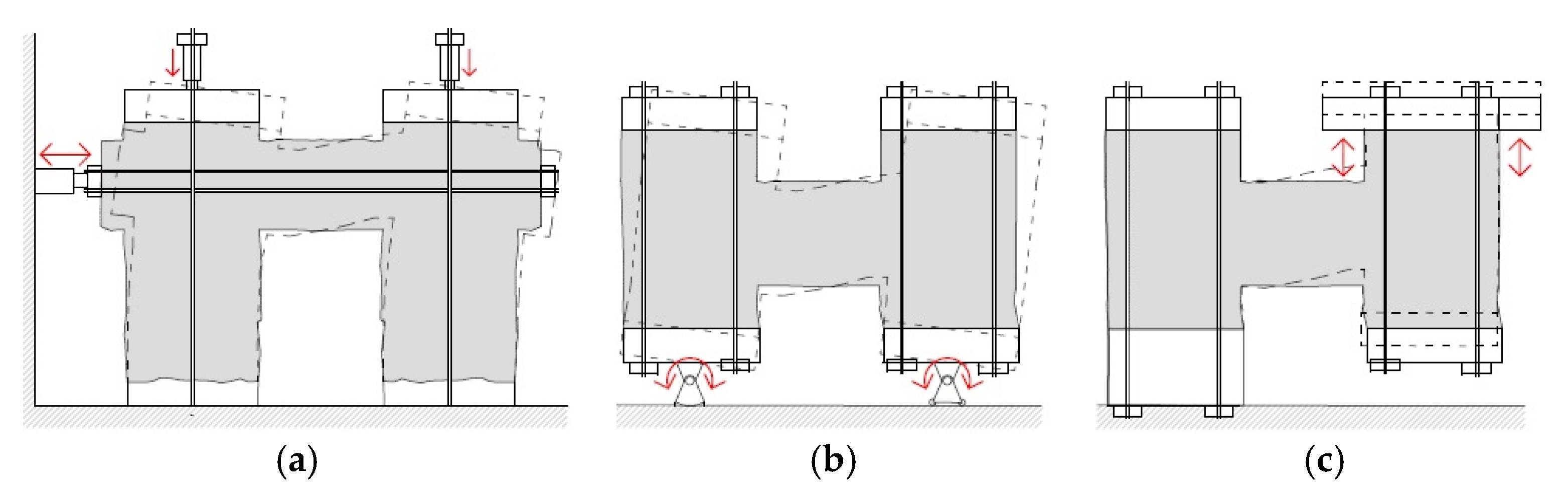
Actually, the failure mechanisms identified in Figure 1 can also affect the spandrels, which behavior can be influenced by some interlocking effect at the extremities and by the presence of lintels, ties or ring beams at floor level. To investigate, Augenti et al. [58] and Ismail and Ingham [9] considered TT-shape panels composed of two piers and a spandrel and performed horizontal cyclic tests under constant vertical load (Figure 4a). In particular, Augenti et al. [58] tested a tuff masonry wall provided with a wooden lintel: the unreinforced configuration was previously damaged, then the spandrel (dimensions 310 × 1700 × 1000 mm3) was repaired with TRM at both sides. The rocking of the piers always governed the global behavior, but the TRM opposed the failure of the spandrels through diffusive cracking, allowing energy dissipation. Ismail and Ingham [9] tested a solid brick masonry wall and compared the results of unstrengthened, strengthened and damaged-repaired spandrels (dimensions 220 × 1230 × 940 mm3) but applied the TRM system to one side only. The TRM actively contributed to the energy dissipation in the repaired configuration (the tensile rupture of the textile was attained); while remaining un-cracked in the strengthened sample, in which the diagonal cracking of a pier occurred. From both studies, no relevant debonding phenomena emerged between the TRM and the masonry.
A different setup for cyclic tests on H-shape samples was adopted by Gams et al. [59], who pre-compressed the masonry piers and then achieved the spandrel deformation by applying a simultaneous rotation at the base of the piers (Figure 4b). The performances of rubble stone masonry spandrels with timber lintels (dimensions 350 × 1050 × 1120 mm3), damaged and then repaired with TRM at one or both sides, were investigated. Strengthened spandrels showed an extensive spread of damage and attained failure for the fiber yarns to rupture at the extremities, performing a significant increase in both resistance and displacement capacities.
Even though it has not yet been applied to masonry strengthened with TRM, it is worth mentioning a further setup suitable for testing masonry spandrels (Figure 4c), adopted by Gattesco et al. [16]: the masonry assemblage still has an H-shape and the piers are pre-compressed, but one pier is fixed at the base while the other one is subjected to cyclic up-down lifts.
2.2. Out-of-Plane Loading
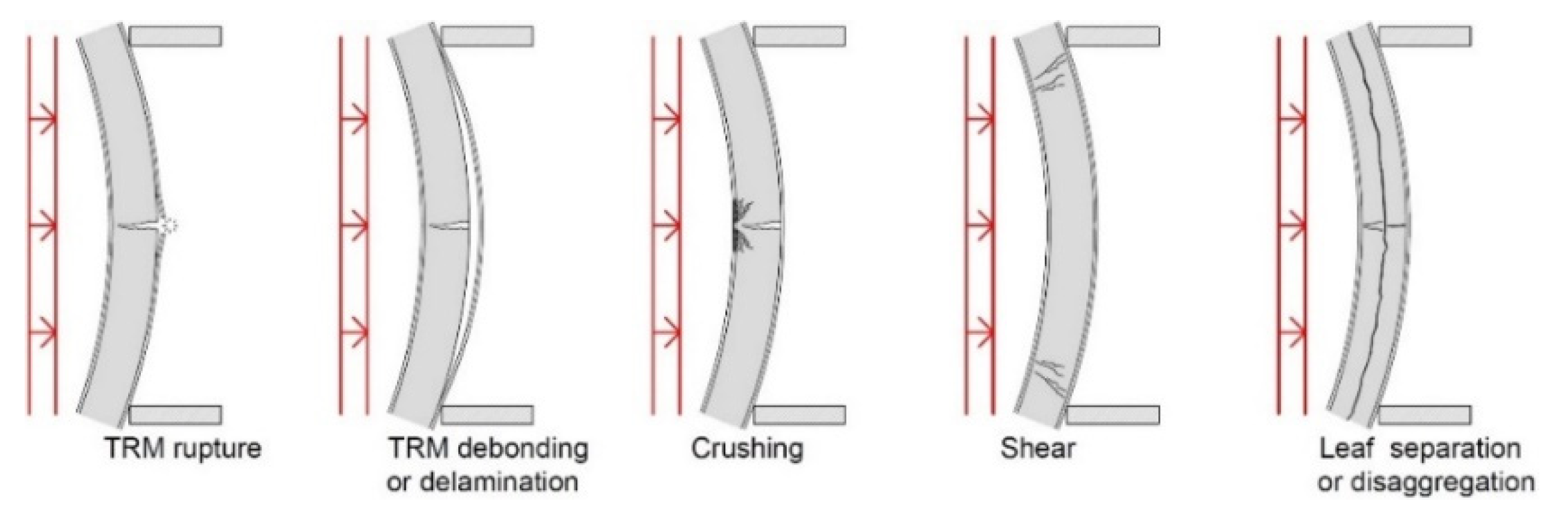
Based on post-earthquake surveys, the out-of-plane collapse of unreinforced masonry walls is rather frequent, especially in buildings having relatively flexible floor diaphragms or with high rooms. In laboratory testing (e.g., [60]), flexural failure generally occurs: it is characterized by the cracking of the most stressed section, on the tensed side, and the subsequent activation of the rocking mechanism due to the presence of axial load. The TRM application proved effective in enhancing the out-of-plane performances of masonry walls, contrasting the activation of the rocking mechanism. Depending on the geometry, the material properties, as well as the loading and boundary conditions, the out-of-plane failure of TRM-strengthened masonry typically occurs for the rupture or the debonding of the TRM on the tensed side, for crushing on the compressed side, for shear failure or, in very weak masonry, for leaf separation/disaggregation (Figure 5).
Table 3 sums up the main features adopted in the literature for testing the TRM effectiveness against out-of-plane failure. The tests concerned mostly one-dimensional bending, according to a three-point [31,38,43,61,62,63,64] or four-point flexural scheme [65,66,67,68,69]. Alternative setups considered air-bag tests [9,70], uniform loading [71], eccentric compression [72] and bi-dimensional bending with un-symmetric boundary conditions [73]. Samples were usually arranged horizontally (specimens length till about 1500 mm, width range 100–440 mm), with bending perpendicular to the bed joints; however, bending parallel to the bed joints was also tested [61,68,69]. In addition, the vertical arrangement was adopted for masonry walls up to 3670 mm tall [9,38,67,70,72,73,74] and, sometimes, pre-loaded with an additional axial compression [31,71]. The bending action was applied mostly monotonically or following loading–unloading procedures [66,70,71]; in addition, cyclic tests were performed [9,43,61,65]. The results were reported in terms of applied load at the varying of the mid-span deflection.
The TRM application generally improved the out-of-plane performances of the masonry in terms of both strength and displacement capacities. Strengthened specimens typically presented multiple parallel cracks in the mortar matrix, due to the capability of the embedded reinforcement in distributing flexural stresses, as clearly emerged also from comparison with masonry samples provided by bare plaster [31]. The obtained load-displacement curves showed an almost bilinear trend, according to an un-cracked and a cracked stage; negligible benefits emerged from samples with TRM applied on the compressed side only. The orientation of the masonry bed joints did not significantly influence the results of strengthened samples due to the negligible contribution of the masonry tensile strength. The combination of high-performance reinforcements with weak interaction among the components tended to turn the failure mode from the TRM tensile failure to delamination or debonding phenomena or to shear collapse [62,70].
Considering that pseudo-static loading procedures tend to be more severe than seismic action, De Santis et al. [74] tested the effects of dynamic loading on unreinforced and damaged-repaired masonry samples. The shaking table tests evidenced the effectiveness of the embedded reinforcement, even if some debonding occurred. Moreover, the tests evidenced the fundamental role of transversal ties in preventing leaf separation/disaggregation and in ensuring stress transfer from the masonry to the fabric at advanced damage levels.
3. Design Methods
Design methods for TRM-strengthened structures are aimed at providing simple, practice-oriented correlations to be used by professionals. The available design methods are mainly aimed at resistance estimation, while there is, in general, a lack of strategies for the prediction of the deformation capacities. The main approaches concerning both in-plane and out-of-plane loading are discussed in the following.
3.1. In-Plane Loading
The estimation of the in-plane shear resistance of TRM-strengthened masonry elements is typically based on the sum of the contribution of the plain masonry and that of the TRM layer(s). For this latter, the common approach (applied, e.g., in [17,22,27,41,68,75] when analyzing diagonal compression tests) considers the embedded fiber-based reinforcement only, as indicated in AC434 [76], CNR-DT 215/2018 [77] and ACI 549.6R-20 [78]. Thus, as also evidenced by Ferrara et al. [10], it is assumed that the maximum capacity coincides with the textile failure, while the masonry is exploiting its maximum resistance; but this could be questionable in many cases. Moreover, depending on the guideline, the evaluation criteria for the maximum allowable tensile stress of the textile may be reduced so as to account for premature debonding; however, in general, these methods, derived from FRP systems (based on organic matrices) and sometimes quite suitable also for TRM with thin mortar matrices (≤10 mm thick), lead to extremely conservative evaluations of the maximum resistance in case of thicker mortar coatings (>15 mm). As a result, some authors referred to the tensile strength of the mortar, instead of that of the textile, for more accurate predictions of the peak load [19,38], while the role of the textile was recognized as fundamental to ensuring a pseudo-ductile behavior in the post-cracking stage. Gattesco and Boem [25] also introduced a correction coefficient, empirically evaluated, considering that the peak resistance of the masonry and that of the TRM may not be achieved simultaneously (it depends on the stiffness and the brittleness of the coupled materials). In Angiolilli et al. [30], the corrective factor accounted for the actual effectiveness of the bond between the mortar coating and the masonry. Wang et al. [36] proposed to evaluate two different load levels for the TRM-strengthened masonry: at the serviceability limit state, considering the mortar matrix contribution, and at the ultimate limit state, considering the textile contribution. Gams et al. [54], focusing on shear-compression tests, proved that, when the collapse is governed by diagonal cracking, the lateral resistance can be evaluated by considering the sole contribution of the textile crossing the diagonal crack, since masonry is largely damaged at that stage; however, the premature TRM debonding can generally limit the full fibers exploitation.
In regard to the in-plane bending resistance of TRM-strengthened masonry elements, the common evaluation strategy, suggested by CNR-DT 215/2018 [77] and ACI 549.6R-20 [78], is based on the well-known approach for RC beams subjected to combined axial and bending. The contribution of the masonry in compression and that of the textile in tension is typically considered [44,79]. When an effective anchoring of the TRM system is ensured at the extremities of the masonry panel and the bond between TRM and masonry is guaranteed, the collapse can generally be induced by the crushing of the masonry or by the tensile failure of the TRM. Otherwise, a reduced ultimate stress/strain for the TRM layer, accounting for premature debonding, should be considered.
3.2. Out-of-Plane Loading
A similar approach was applied to the evaluation of the out-of-plane bending resistance, although the results can differ for some modifications on the basic assumptions, as observed by Sagar et al. [68] and Tripathy et al. [80]. For example, D’Antino et al. [81] accounted for possible TRM delamination since its behavior was derived from TRM characterization bond tests on masonry substrate; Padalu et al. [82] also accounted for the tensile contribution of the masonry; Babaeidarabad et al. [70] and Gattesco and Boem [67] also considered possible masonry failure in shear; Harajli et al. [65] applied a strain reduction factor to account for the masonry shear failure and for TRM debonding. Based on analytical equations, Belliazzi et al. [83] drew dimensionless interaction diagrams (axial load vs. bending moment) useful for design purposes at the varying the masonry thickness and reinforcement ratio; confined masonry panels under horizontal bending were also analyzed. A different approach, based on limit analysis, was proposed by De Santis et al. [74]: it was assumed that both the masonry and TRM exploit their full strength at the same time; premature debonding was accounted for by applying a correction coefficient to the estimated resistance.
A few methods for the calculations of the ultimate bending deflection were also proposed in the case of out-of-plane loading: the approach typically adopted for the estimation of the RC cracked beams [84] was applied by Babaeidarabad et al. [70], combining the contributions to deflection of uncracked and cracked cross sections. Meriggi et al. [85] considered the mechanism of two rigid blocks rotating after a flexural cracking; the composite-to-substrate relative displacement occurred uniformly over a calibrated development length across the crack, in which the textile attained its ultimate strain.
4. Numerical Modeling
The numerical studies available in the literature on TRM mostly focused on the tensile and bond behavior of TRM coupons, which have already been extensively analyzed by the author [1]. Some numerical analyses were also performed to simulate the behavior of TRM-strengthened masonry at the structural element level and to investigate deeper the influence of the strengthening system characteristics on the in-plane and out-of-plane element performances.
In the framework of the Finite-Element (FE) methods, the well-known, consolidated modeling strategies developed over the past years for unreinforced masonry elements are principally based on discrete elements approaches or on a continuum [86,87]. In the FE discrete approach, the masonry units and the mortar joints are modeled separately by means of distinct 2D or 3D elements, connected directly or through interfaces; simplified discrete methods assume the masonry units bonded with interfaces accounting for both FE, the mortar and the unit–mortar interaction. In the FE modeling approach based on a continuum, masonry is treated as a homogeneous material, with an equivalent relationship between average stresses and average strains. In FE methods, the behavior of the components is expressed in the form of differential equations that relate to the mechanical field variables (strain and stresses).
As an alternative to FE methods, the Discrete Element Method (DEM) uses distinct particle entities for the masonry units, whose interaction is governed by contact detection algorithms and contact models [88,89]. DEM implies a dynamic process in which the unknowns are solved explicitly by the differential equations of Newton’s laws of motion, making finite displacement simulations easy to perform with respect to FE methods. The combined Finite–Discrete Element Method (FDEM) implements a finite element mesh discretization of the particle [90,91]. DEM and FDEM methods are particularly useful for the study of systems made of discontinuous media, such as masonry.
Extensive discussion on the different modeling approaches adopted for unstrengthened masonry can be found in [92]. In comparison, the FE discrete modeling approach applied on TRMs implies distinct elements for the mortar matrix and for the embedded fiber grid and interfaces between the grid and the matrix and the matrix and the masonry substrate. On the other side, according to an FE approach based on a continuum, interfaces are replaced by perfect bond assumptions and the TRM equivalent characteristics are calibrated on the bases of tensile and shear bond experimental characterization tests on TRM coupons. Models based on a continuum are more time-efficient and thus suitable also for the application at a larger scale (wide elements, entire walls and buildings) but necessitate the definition of the equivalent material models; an issue not yet fully solved for TRM since it requires extensive preliminary campaign in order to calibrate. Despite being time-consuming, discrete models allow more detailed investigations of local interactions among components as well as the calibration and validation of those based on a continuum. Most of the simulations performed on TRM-strengthened masonry elements concerned nonlinear static analysis, accounting for the components’ nonlinearities; typically, for both the masonry and the mortar matrix, different behavior in compression and tension is assumed (e.g., combining Rankine-type for tension and the Von Mises or Hill for compression or applying the Concrete Damage Plasticity model). Generally, the textile is assumed as elastic–brittle in tension, while the matrix–masonry and the textile–matrix interfaces are mostly governed by nonlinear shear bond-slip laws.
To the author’s knowledge, the application of DEM or FDEM modeling approaches to the simulation of TRM-strengthened masonry elements is, though promising, just in the very early stages [93,94].
4.1. In-Plane Loading
For the modeling of diagonal compression tests, Basili et al. [34,95] applied a bi-dimensional, continuum modeling approach (software Midas FEA) based on perfectly bonded layers representing the masonry, the mortar matrix and the textile. The layers were made of 8-node quadrilateral plane stress elements; a reduced resistance was set for the textile to take debonding indirectly into account. This approach was also considered by Garofano et al. [96] for modeling shear-compression tests (TNO Diana). Differently, Wang et al. [97] modeled the embedded mesh through a grid perfectly bonded to the matrix and the effect of fibers-to-mortar bond behavior was considered by calibrating an appropriate tension softening for the mortar.
Corradi et al. [98] (by using Ansys) and Gattesco et al. [99] (by using Midas FEA) simulated diagonal compression tests by adopting 8-node solid elements for the masonry (treated as homogeneous material) and the mortar coating, combined with truss elements for the embedded grid; perfect bond among the components was assumed. A similar TRM modeling was also considered by Castori et al. [100] (Ansys), but with a discrete approach for the masonry (bricks and mortar joints); the strength of the grid was reduced so as to indirectly account for debonding. Lignola et al. [101] considered, for the TRM, an equivalent homogeneous material accounting for both the contribution of the mortar matrix and of the embedded fibers.
Ungureanu et al. [102] combined through interfaces the solid elements representing the bricks and the mortar joints and the shell elements representing the TRM system. Murgo et al. [103] (Diana Fea) used linear-elastic bi-dimensional elements for the masonry bricks and the mortar render and truss elements for the embedded grid; the nonlinearities of both the masonry and the plaster were lumped at the interfaces in correspondence with the joints. In addition, the interactions between the fiber grid and the matrix were governed by nonlinear shear interfaces, while a perfect bond was assumed between the coating and the masonry substrate.
Bertolesi et al. [104] (Abaqus) modeled the masonry by means of rigid quadrilateral elements linked by shear and normal nonlinear springs; the TRM was introduced by means of equivalent truss elements perfectly bonded at the ends to the rigid bodies’ centroids, provided with a behavior accounting for the fibers pull-out. Moreover, the same authors applied a 3D discrete modeling strategy, based on 8-node solid elements and trusses. Both models fitted reasonably to the experimental performances, despite more rough results from the simplified model, it resulted in being significantly more time efficient. In addition, Lignola et al. [105] (TNO Diana) opted for a similar discrete modeling approach.
Parisi et al. [79] (Diana) modeled a piers-spandrel subassemblage: the discrete model consisted of 8-node isotropic shell elements for the masonry units and the mortar joints (no interfaces); the TRM reinforcement was modeled through equivalent trusses accounting for different behavior in tension and compression.
Even concerning a strengthening system quite different from TRM (steel grids glued to the masonry), it is worth mentioning the modeling approach adopted by Zizi et al. [106] (Abaqus environment) to simulate cyclic shear compression tests by means of 4-node shell elements: the Concrete Damage Plasticity material model considered for the masonry was proved able to account for the material deterioration during the cyclic fracturing process and to control the stiffness recovering during load reversals.
A different approach was adopted by Angiolilli et al. [94], who calibrated a lattice DEM to simulate diagonal compression tests. The irregular stone masonry units were treated as rigid bodies interacting with each other through appropriate constitutive equations; frictional penalty constraints joined the mortar matrix particles and the masonry ones; elastic beam elements were added to simulate the fiber strands, which were connected to the mortar particles through penalty constraints.
4.2. Out-of-Plane Loading
In regard to the simulations of out-of-plane performances, Bellini et al. [71] (Diana) developed a bi-dimensional model based on the plane stress hypothesis to study vertical sections of masonry walls under nonlinear cyclic analysis (loading–unloading). The discrete modeling approach was adopted for the masonry and the TRM was introduced by means of three layers, the outers representing the mortar coating, the inner the embedded composite grid; interface elements were introduced to account for grid debonding phenomena.
Even focused on mortar reinforced with short fibers, it is worth also mentioning the model based on the continuum approach developed by Colombo et al. [107] (software FEMIX 4.0): 8-node plane stress elements represented both the masonry and the strengthening layer; the latter had an equivalent quadrilinear tensile softening.
To study unsymmetrical out-of-plane bending, D’Ambra et al. [108] (Diana) developed a simplified discrete 3D model for the masonry (20-node elastic solid elements connected through nonlinear quadrilateral interfaces); the homogenized behavior of the TRM layer was represented by plane stress elements connected to the masonry substrate by means of quadrilateral interfaces. The same tests were also simulated by Scacco et al. [109] (Abaqus), who developed two different 3D numerical models for the masonry: the former was a detailed discrete model using 8-node solid elements; the latter applied a so-called “discretized homogenization” based on elastic triangular prism units linked by vertical, horizontal and diagonal nonlinear joints. In both of the models, the mortar matrix was considered through 8-node solid elements with embedded equivalent truss elements for the reinforcement (a perfect bond was assumed). Through the less refined mesh, the second approach led to comparable results, allowing the reproduction of the correct damage pattern with less computational effort.
Noor-E-Khuda et al. [110] developed a Vumat subroutine, suitable for the Abaqus explicit algorithm, capable of examining the out-of-plane behavior of TRM-strengthened masonry elements through layered shells. The inner layer represented the masonry and the outer layers the TRM (as an equivalent material). Moreover, 4-node membrane-strain elements with a single Gaussian integration point at the element centroid were considered and five Simpson’s integration points for each layer were used; the material nonlinearities of the different layers were considered.
5. Conclusions
The wide scenario of the state-of-the-art concerning masonry elements strengthened through Textile-Reinforced Mortar, extensively analyzed in this paper, evidenced the variety of experimental setups and revealed the burden of testing the reinforcement effectiveness exhaustively since it strictly related to the selected configurations in terms of materials, mutual interactions, geometry, load pattern and boundary conditions. Targeted experimentations, however, allowed researchers to recognize the possible resistant mechanisms and to develop simplified design strategies for the prediction of the performances; however, they are still far away from being exhaustive, especially in terms of strain capacity predictions. The analysis of the available numerical methods pointed out the lack of a comprehensive approach, rather than models calibrated and applied for the reproduction of a specific test setup and combination of materials.
Funding
This research has received funding from the European Union’s Horizon 2020 research and innovation program under the Marie Sklodowska-Curie grant agreement No 101003410.
Data Availability Statement
Not applicable.
Acknowledgments
The author wishes to thank the professional help of B. Patzák and A. Kohoutková (Czech Technical University in Prague—CTU).
Conflicts of Interest
The author declares no conflict of interest.
References
- Boem, I. Characterization of textile-reinforced mortar: State of the art and detailed level modelling with a free open-source finite element code. J. Compos. Constr. 2022, 26, 4022060. [Google Scholar] [CrossRef]
- Cordis Website. Available online: https://cordis.europa.eu/project/id/101003410 (accessed on 4 August 2022).
- ConFiRMa Website. Available online: https://sites.google.com/view/confirmaproject (accessed on 4 August 2022).
- Atalić, J.; Uroš, M.; Šavor Novak, M.; Demšić, M.; Nastev, M. The Mw5.4 Zagreb (Croatia) earthquake of March 22, 2020: Impacts and response. Bull. Earthq. Eng. 2021, 19, 3461–3489. [Google Scholar] [CrossRef]
- Sorrentino, L.; Cattari, S.; Da Porto, F.; Magenes, G.; Penna, A. Seismic behaviour of ordinary masonry buildings during the 2016 central Italy earthquakes. Bull. Earthq. Eng. 2019, 17, 5583–5607. [Google Scholar] [CrossRef]
- Penna, A.; Morandi, P.; Rota, M.; Manzini, C.F.; Da Porto, F.; Magenes, G. Performance of masonry buildings during the Emilia 2012 earthquake. Bull. Earthq. Eng. 2014, 12, 2255–2273. [Google Scholar] [CrossRef]
- Ural, A.; Doğangün, A.; Sezen, H.; Angın, Z. Seismic performance of masonry buildings during the 2007 Bala, Turkey earthquakes. Nat. Hazards 2012, 60, 1013–1026. [Google Scholar] [CrossRef]
- Parisi, F.; Iovinella, I.; Balsamo, A.; Augenti, N.; Prota, A. In-plane behaviour of tuff masonry strengthened with inorganic matrix–grid composites. Compos. B Eng. 2013, 45, 1657–1666. [Google Scholar] [CrossRef]
- Ismail, N.; Ingham, J.M. In-plane and out-of-plane testing of unreinforced masonry walls strengthened using polymer textile reinforced mortar. Eng. Struct. 2016, 118, 167–177. [Google Scholar] [CrossRef]
- Ferrara, G.; Caggegi, C.; Martinelli, E.; Gabor, A. Shear capacity of masonry walls externally strengthened using Flax-TRM composite systems: Experimental tests and comparative assessment. Constr. Build. Mater. 2020, 261, 120490. [Google Scholar] [CrossRef]
- Turnsek, V.; Sheppard, P. The shear and flexural resistance of masonry walls. In Proceedings of the International Research Conference on Earthquake Engineering, Skopje, Yugoslavia, 30 June–3 July 1980. [Google Scholar]
- Magenes, G.; Calvi, G.M. In-plane seismic response of brick masonry walls. Earthq. Eng. Struct. Dyn. 1997, 26, 1091–1112. [Google Scholar] [CrossRef]
- Petry, S.; Beyer, K. Influence of boundary conditions and size effect on the drift capacity of URM walls. Eng. Struct. 2014, 65, 76–88. [Google Scholar] [CrossRef] [Green Version]
- Beyer, K.; Dazio, A. Quasi-static cyclic tests on masonry spandrels. Earthq. Spectra 2012, 28, 907–929. [Google Scholar] [CrossRef]
- Graziotti, F.; Magenes, G.; Penna, A. Experimental cyclic behaviour of stone masonry spandrels. In Proceedings of the 15th World Conference on. Earthquake Engineering 15WCEE, Lisbon, Portugal, 24–28 September 2012. [Google Scholar]
- Gattesco, N.; Macorini, L.; Dudine, A. Experimental response of brick-masonry spandrels under in-plane cyclic loading. J. Struct. Eng. 2016, 142, 04015146. [Google Scholar] [CrossRef]
- Almeida, J.A.P.P.; Pereira, E.B.; Barros, J.A.O. Assessment of overlay masonry strengthening system under in-plane monotonic and cyclic loading using the diagonal tensile test. Constr. Build. Mater. 2015, 94, 851–865. [Google Scholar] [CrossRef]
- Borri, A.; Castori, G.; Corradi, M.; Speranzini, E. Shear behavior of unreinforced and reinforced masonry panels subjected to in situ diagonal compression tests. Constr. Build. Mater. 2011, 25, 4403–4414. [Google Scholar] [CrossRef]
- D’Antino, T.; Carozzi, F.G.; Poggi, C. Diagonal shear behavior of historic walls strengthened with composite reinforced mortar (CRM). Mater. Struct. 2019, 52, 114. [Google Scholar] [CrossRef]
- ASTM E519/E519M-21; Standard Test Method for Diagonal Tension (Shear) in Masonry Assemblages. ASTM: West Conshohocken, PA, USA, 2021.
- Rilem, T.C. (Ed.) LUM B6 Diagonal tensile strength tests of small wall specimens. In RILEM Recommendations for the Testing and Use of Constructions Materials; E & FN SPON: New York, NY, USA, 1994; pp. 488–489. [Google Scholar]
- Babaeidarabad, S.; De Caso, F.; Nanni, A. URM Walls Strengthened with Fabric-Reinforced Cementitious Matrix Composite Subjected to Diagonal Compression. J. Compos. Constr. 2014, 18, 04013045. [Google Scholar] [CrossRef]
- Menna, C.; Asprone, D.; Durante, M.; Zinno, A.; Balsamo, A.; Prota, A. Structural behaviour of masonry panels strengthened with an innovative hemp fibre composite grid. Constr. Build. Mater. 2015, 100, 111–121. [Google Scholar] [CrossRef]
- Gattesco, N.; Boem, I.; Dudine, A. Diagonal compression tests on masonry walls strengthened with a GFRP mesh reinforced mortar coating. Bull. Earthq. Eng. 2015, 13, 1703–1726. [Google Scholar] [CrossRef]
- Gattesco, N.; Boem, I. Experimental and analytical study to evaluate the effectiveness of an in-plane reinforcement for masonry walls using GFRP meshes. Constr. Build. Mater. 2015, 88, 94–104. [Google Scholar] [CrossRef]
- Garcia-Ramonda, L.; Pelá, L.; Roca, P.; Camata, G. In-plane shear behaviour by diagonal compression testing of brick masonry walls strengthened with basalt and steel textile reinforced mortars. Constr. Build. Mater. 2020, 240, 117905. [Google Scholar] [CrossRef]
- Del Zoppo, M.; Di Ludovico, M.; Balsamo, A.; Prota, A. In-plane shear capacity of tuff masonry walls with traditional and innovative Composite Reinforced Mortars (CRM). Constr. Build. Mater. 2019, 210, 289–300. [Google Scholar] [CrossRef]
- Borri, A.; Corradi, M.; Sisti, R.; Buratti, C.; Belloni, E.; Moretti, E. Masonry wall panels retrofitted with thermal-insulating GFRP-reinforced jacketing. Mater. Struct. 2016, 49, 3957–3968. [Google Scholar] [CrossRef]
- Carozzi, F.G.; D’Antino, T.; Poggi, C. In-situ experimental tests on masonry panels strengthened with Textile Reinforced Mortar composites. Procedia Struct. Integr. 2018, 11, 355–362. [Google Scholar] [CrossRef]
- Angiolilli, M.; Gregori, A.; Cattari, S. Performance of Fiber Reinforced Mortar coating for irregular stone masonry: Experimental and analytical investigations. Constr. Build. Mater. 2021, 294, 123508. [Google Scholar] [CrossRef]
- D’Ambrisi, A.; Mezzi, M.; Caporale, A. Experimental investigation on polymeric net-RCM reinforced masonry panels. Compos. Struct. 2013, 105, 207–215. [Google Scholar] [CrossRef]
- Prota, A.; Marcari, G.; Fabbrocino, G.; Manfredi, G.; Aldea, C. Experimental In-Plane Behavior of Tuff Masonry Strengthened with Cementitious Matrix–Grid Composites. J. Compos. Constr. 2006, 10, 223–233. [Google Scholar] [CrossRef]
- Marcari, G.; Basili, M.; Vestroni, F. Experimental investigation of tuff masonry panels reinforced with surface bonded basalt textile-reinforced mortar. Compos. B Eng. 2017, 108, 131–142. [Google Scholar] [CrossRef]
- Basili, M.; Vestroni, F.; Marcari, G. Brick masonry panels strengthened with textile reinforced mortar: Experimentation and numerical analysis. Constr. Build. Mater. 2019, 227, 117061. [Google Scholar] [CrossRef]
- Benedetti, A. In Plane Behaviour of Masonry Walls Reinforced with Mortar Coatings and Fibre Meshes. Int. J. Archit. 2019, 13, 1029–1041. [Google Scholar] [CrossRef]
- Wang, X.; Lam, C.C.; Iu, V.P. Comparison of different types of TRM composites for strengthening masonry panels. Constr. Build. Mater. 2019, 219, 184–194. [Google Scholar] [CrossRef]
- Crisci, G.; Ceroni, F.; Lignola, G.P. Comparison between Design Formulations and Numerical Results for In-Plane FRCM-Strengthened Masonry Walls. Appl. Sci. 2020, 10, 4998. [Google Scholar] [CrossRef]
- Donnini, J.; Maracchini, G.; Lenci, S.; Corinaldesi, V.; Quagliarini, E. TRM reinforced tuff and fired clay brick masonry: Experimental and analytical investigation on their in-plane and out-of-plane behavior. Constr. Build. Mater. 2021, 272, 121643. [Google Scholar] [CrossRef]
- Oskouei, A.V.; Jafari, A.; Bazli, M.; Ghahri, R. Effect of different retrofitting techniques on in-plane behavior of masonry wallettes. Constr. Build. Mater. 2018, 169, 578–590. [Google Scholar] [CrossRef]
- Yardim, Y.; Lalaj, O. Shear strengthening of unreinforced masonry wall with different fiber reinforced mortar jacketing. Constr. Build. Mater. 2016, 102, 149–154. [Google Scholar] [CrossRef]
- Casacci, S.; Gentilini, C.; Di Tommaso, A.; Oliveira, D.V. Shear strengthening of masonry wallettes resorting to structural repointing and FRCM composites. Constr. Build. Mater. 2019, 206, 19–34. [Google Scholar] [CrossRef]
- Papanicolaou, C.G.; Triantafillou, T.C.; Karlos, K.; Papathanasiou, M. Textile-reinforced mortar (TRM) versus FRP as strengthening material of URM walls: In-plane cyclic loading. Mater. Struct. 2007, 40, 1081–1097. [Google Scholar] [CrossRef]
- Papanicolaou, C.G.; Triantafillou, T.C.; Lekka, M. Externally bonded grids as strengthening and seismic retrofitting materials of masonry panels. Constr. Build. Mater. 2011, 25, 504–514. [Google Scholar] [CrossRef]
- Boem, I.; Gattesco, N. Rehabilitation of masonry buildings with Fibre Reinforced Mortar: Practical design considerations concerning seismic resistance. In Key Engineering Materials; Trans Tech Publications Ltd.: Bäch, Switzerland, 2021; Volume 898, pp. 1–7. [Google Scholar]
- Corradi, M.; Borri, A.; Poverello, E.; Castori, G. The use of transverse connectors as reinforcement of multi-leaf walls. Mater. Struct. 2017, 50, 114. [Google Scholar] [CrossRef]
- Cascardi, A.; Leone, M.; Aiello, M.A. Transversal joining of multi-leaf masonry through different types of connector: Experimental and theoretical investigation. Constr. Build. Mater. 2020, 265, 120733. [Google Scholar] [CrossRef]
- Gattesco, N.; Amadio, C.; Bedon, C. Experimental and numerical study on the shear behavior of stone masonry walls strengthened with GFRP reinforced mortar coating and steel-cord reinforced repointing. Eng. Struct. 2015, 90, 143–157. [Google Scholar] [CrossRef] [Green Version]
- Mercedes, L.; Bernat-Maso, E.; Gil, L. In-plane cyclic loading of masonry walls strengthened by vegetal-fabric-reinforced cementitious matrix (FRCM) composites. Eng. Struct. 2020, 221, 111097. [Google Scholar] [CrossRef]
- Garcia-Ramonda, L.; Pelà, L.; Roca, P.; Camata, G. Cyclic shear-compression testing of brick masonry walls repaired and retrofitted with basalt textile reinforced mortar. Compos. Struct. 2021, 283, 115068. [Google Scholar] [CrossRef]
- Guerreiro, J.; Proença, J.; Ferreira, J.G.; Gago, A. Experimental characterization of in-plane behaviour of old masonry walls strengthened through the addition of CFRP reinforced render. Compos. B Eng. 2018, 148, 14–26. [Google Scholar] [CrossRef]
- Tomaževič, M. Earthquake-Resistant Design of Masonry Buildings, Series on Innovation in Structures and Construction; Imperial College Press: London, UK, 1999. [Google Scholar]
- Hračov, S.; Pospíšil, S.; Garofano, A.; Urushadze, S. In-plane cyclic behaviour of unfired clay and earth brick walls in both unstrengthened and strengthened conditions. Mater. Struct. 2016, 49, 3293–3308. [Google Scholar] [CrossRef]
- Tomaževič, M.; Gams, M.; Berset, T. Strengthening of stone masonry walls with composite reinforced coatings. Bull. Earthq. Eng. 2015, 13, 2003–2027. [Google Scholar] [CrossRef]
- Gams, M.; Tomaževič, M.; Berset, T. Seismic strengthening of brick masonry by composite coatings: An experimental study. Bull. Earthq. Eng. 2017, 15, 4269–4298. [Google Scholar] [CrossRef]
- Türkmen, Ö.S.; De Vries, B.T.; Wijte, S.N.M.; Vermeltfoort, A.T. Quasi-static cyclic in-plane testing of masonry walls strengthened with a single-sided fabric-reinforced cementitious matrix overlay and flexible anchorage. J. Build. Rehabil. 2019, 4, 8. [Google Scholar] [CrossRef]
- Torres, B.; Ivorra, S.; Javier Baeza, F.; Estevan, L.; Varona, B. Textile reinforced mortars (TRM) for repairing and retrofitting masonry walls subjected to in-plane cyclic loads. An experimental approach. Eng. Struct. 2021, 231, 111742. [Google Scholar] [CrossRef]
- Messali, F.; Metelli, G.; Plizzari, G. Experimental results on the retrofitting of hollow brick masonry walls with reinforced high performance mortar coatings. Constr. Build. Mater. 2017, 141, 619–630. [Google Scholar] [CrossRef]
- Augenti, N.; Parisi, F.; Prota, A.; Manfredi, G. In-Plane Lateral Response of a Full-Scale Masonry Subassemblage with and without an Inorganic Matrix-Grid Strengthening System. J. Compos. Constr. 2011, 15, 578–590. [Google Scholar] [CrossRef]
- Gams, M.; Farič, M.; Pučnik, V. Eksperimentalne raziskave utrjenih prekladnih delov kamnitih zidov [Experimental research of strengthened stone masonry spandrels. In Proceedings of the 42nd Assembly of Building Constructors of Slovenia, SDGK—Slovenian Society of building constructors, Ljubljana, Slovenia, 7 October 2021. (In Slovenian). [Google Scholar]
- Dazio, A. The effect of the boundary conditions on the out-of-plane behavior of un-reinforced masonry walls. In Proceedings of the 14th World Conference on Earthquake Engineering, Beijing, China, 12–17 October 2008. [Google Scholar]
- Papanicolaou, C.G.; Triantafillou, T.C.; Papathanasiou, M.; Karlos, K. Textile reinforced mortar (TRM) versus FRP as strengthening material of URM walls: Out-of-plane cyclic loading. Mater. Struct. 2007, 41, 143–157. [Google Scholar] [CrossRef]
- Bernat-Maso, E.; Escrig, C.; Aranha, C.A.; Gil, L. Experimental assessment of Textile Reinforced Sprayed Mortar strengthening system for brickwork wallettes. Constr. Build. Mater. 2014, 50, 226–236. [Google Scholar] [CrossRef]
- Valluzzi, M.R.; Garbin, E.; Panizza, M. Out-of-plane behaviour of infill masonry panels strengthened with composite materials. Mater. Struct. 2014, 47, 2131–2145. [Google Scholar] [CrossRef]
- Kariou, F.A.; Triantafyllou, S.P.; Bournas, D.A.; Koutas, L.N. Out-of-plane response of masonry walls strengthened using textile-mortar system. Constr. Build. Mater. 2018, 165, 769–781. [Google Scholar] [CrossRef]
- Harajli, M.; ElKhatib, H.; San-Jose, J.T. Static and Cyclic Out-of-Plane Response of Masonry Walls Strengthened Using Textile-Mortar System. J. Mater. Civ. Eng. 2010, 22, 1171–1180. [Google Scholar] [CrossRef]
- Martins, A.; Vasconcelos, G.; Fangueiro, R.; Cunha, F. Experimental assessment of an innovative strengthening material for brick masonry infills. Compos. B Eng. 2015, 80, 328–342. [Google Scholar] [CrossRef]
- Gattesco, N.; Boem, I. Out-of-plane behavior of reinforced masonry walls: Experimental and numerical study. Compos. B Eng. 2017, 128, 39–52. [Google Scholar] [CrossRef]
- Sagar, S.L.; Singhal, V.; Rai, D.C.; Gudur, P. Diagonal shear and out-of-plane flexural strength of Fabric-Reinforced Cementitious Matrix–strengthened masonry wallets. J. Compos. Constr. 2017, 21, 04017016. [Google Scholar] [CrossRef]
- Padalu, P.K.V.R.; Singh, Y.; Das, S. Efficacy of basalt fibre reinforced cement mortar composite for out-of-plane strengthening of unreinforced masonry. Constr. Build. Mater. 2018, 191, 1172–1190. [Google Scholar] [CrossRef]
- Babaeidarabad, S.; Caso, F.D.; Nanni, A. Out-of-Plane behavior of URM walls strengthened with Fabric-Reinforced Cementitious Matrix composite. J. Compos. Constr. 2014, 18, 04013057. [Google Scholar] [CrossRef]
- Bellini, A.; Incerti, A.; Bovo, M.; Mazzotti, C. Effectiveness of FRCM reinforcement applied to masonry walls subject to axial force and out-of-plane loads evaluated by experimental and numerical studies. Int. J. Archit. 2018, 12, 376–394. [Google Scholar] [CrossRef]
- Cevallos, O.A.; Olivito, R.S.; Codispoti, R.; Ombres, L. Flax and polyparaphenylene benzobisoxazole cementitious composites for the strengthening of masonry elements subjected to eccentric loading. Compos. B Eng. 2015, 71, 82–95. [Google Scholar] [CrossRef]
- D’Ambra, C.; Lignola, G.P.; Prota, A.; Sacco, E.; Fabbrocino, F. Experimental performance of FRCM retrofit on out-of-plane behaviour of clay brick walls. Compos. B Eng. 2018, 148, 198–206. [Google Scholar] [CrossRef]
- De Santis, S.; De Canio, G.; de Felice, G.; Meriggi, P.; Roselli, I. Out-of-plane seismic retrofitting of masonry walls with Textile Reinforced Mortar composites. Bull. Earthq. Eng. 2019, 17, 6265–6300. [Google Scholar] [CrossRef]
- Del Zoppo, M.; Di Ludovico, M.; Prota, A. Analysis of FRCM and CRM parameters for the in-plane shear strengthening of different URM types. Compos. B Eng. 2019, 171, 20–33. [Google Scholar] [CrossRef]
- AC434. Acceptance Criteria for Masonry and Concrete Strengthening Using Fiber-Reinforced Cementitious Matrix (FRCM) Composite Cystems; ICC Evaluation Service, LLC.: Brea, CA, USA, 2011. [Google Scholar]
- CNR-DT 215/2018. Guide for the Design and Construction of Externally Bonded Fibre Reinforced Inorganic Matrix Systems for Strengthening Sxisting Structure; IRIS: Salerno, Italy, 2018. [Google Scholar]
- ACI 549.6R-20; Guide to Design and Construction of Externally Bonded Fabric-Reinforced Cementitious Matrix (FRCM) and Steel-Reinforced Grout (SRG) Systems. American Concrete Institute: Farmington Hills, MI, USA, 2020.
- Parisi, F.; Lignola, G.P.; Augenti, N.; Prota, A.; Manfredi, G. Nonlinear behavior of a masonry subassemblage before and after strengthening with Inorganic Matrix-Grid composites. J. Compos. Constr. 2011, 15, 821–832. [Google Scholar] [CrossRef]
- Tripathy, D.; Meghwal, P.; Singhal, V. Strengthening of Lime Mortar Masonry Wallettes Using Fiber-Reinforced Cementitious Matrix. J. Compos. Constr. 2020, 24, 04020075. [Google Scholar] [CrossRef]
- D’Antino, T.; Carozzi, F.G.; Colombi, P.; Poggi, C. Out-of-plane maximum resisting bending moment of masonry walls strengthened with FRCM composites. Compos. Struct. 2018, 202, 881–896. [Google Scholar] [CrossRef]
- Padalu, P.K.V.R.; Singh, Y.; Das, S. Out-of-plane flexural behaviour of masonry wallettes strengthened using FRP composites and externally bonded grids: Comparative study. Compos. B Eng. 2019, 176, 107302. [Google Scholar] [CrossRef]
- Belliazzi, S.; Ramaglia, G.; Lignola, G.P.; Prota, A. Out-of-plane retrofit of masonry with Fiber-Reinforced Polymer and Fiber-Reinforced Cementitious Matrix systems: Normalized interaction diagrams and effects on mechanisms activation. J. Compos. Constr. 2021, 25, 04020081. [Google Scholar] [CrossRef]
- EN 1992-1-1:2004; Eurocode 2: Design of Concrete Structures—Part 1-1: General Rules and Rules for Buildings. CEN: Bruxelles, Belgium, 2004.
- Meriggi, P.; de Felice, G.; Santis, S. Design of the out-of-plane strengthening of masonry walls with fabric reinforced cementitious matrix composites. Constr. Build. Mater. 2020, 240, 117946. [Google Scholar] [CrossRef]
- Lourenço, P.B.; Rots, J.G. Multisurface Interface Model for Analysis of Masonry Structures. J. Eng. Mech. 1997, 123, 660–668. [Google Scholar] [CrossRef]
- Lourenço, P.B.; Rots, J.G.; Blaauwendraad, J. Continuum model for masonry: Parameter estimation and validation. J. Struct. Eng. 1998, 124, 642–652. [Google Scholar] [CrossRef]
- Bui, T.T.; Limam, A.; Sarhosis, V.; Hjiajd, M. Discrete element modelling of the in-plane and out-of-plane behaviour of dry-joint masonry wall constructions. Eng. Struct. 2017, 136, 277–294. [Google Scholar] [CrossRef]
- Bora Pulatsu, E.; Bretas, E.M.; Lourenco, P.B. Discrete element modeling of masonry structures: Validation and application. Earthq. Struct. 2016, 11, 563–582. [Google Scholar] [CrossRef]
- Baraldi, D.; Reccia, E.; Cecchi, A. In plane loaded masonry walls: DEM and FEM/DEM models—A critical review. Meccanica 2018, 53, 1613–1628. [Google Scholar] [CrossRef]
- Chen, X.; Wang, H.; Chan, A.H.C.; Agrawal, A.K. Dynamic failure of dry-joint masonry arch structures modelled with the combined finite–discrete element method. Comput. Part. Mech. 2020, 7, 1017–1028. [Google Scholar] [CrossRef]
- Asteris, P.G.; Mohebkhah, A.; Plevris, V.; Papaloizou, L.; Komodromos, P.; Lemos, J.V. Chapter 7: Numerical modeling of historic masonry structures. In Handbook of Research on Seismic Assessment and Rehabilitation of Historic Structures: Advances in Civil and Industrial Engineering; Asteris, P.G., Plevris, V., Eds.; IGI Global: Hershey, PA, USA, 2015; pp. 213–256. [Google Scholar]
- Gobbin, F.; de Felice, G.; Lemos, J.V. A Discrete Element Model for Masonry Vaults Strengthened with Externally Bonded Reinforcement. Int. J. Archit. Herit. 2020, 15, 1959–1972. [Google Scholar] [CrossRef]
- Angiolilli, M.; Gregori, A.; Cusatis, G. Simulating the Nonlinear Mechanical Behavior of FRCM-strengthened Irregular Stone Masonry Walls. Int. J. Archit. Herit. 2021, 16, 1–7. [Google Scholar] [CrossRef]
- Basili, M.; Marcari, G.; Vestroni, F. Nonlinear analysis of masonry panels strengthened with textile reinforced mortar. Eng. Struct. 2016, 113, 245–258. [Google Scholar] [CrossRef]
- Garofano, A.; Ceroni, F.; Pecce, M. Modelling of the in-plane behaviour of masonry walls strengthened with polymeric grids embedded in cementitious mortar layers. Compos. B Eng. 2016, 85, 243–258. [Google Scholar] [CrossRef]
- Wang, X.; Ghiassi, B.; Oliveira, D.V.; Lam, C.C. Modelling the nonlinear behaviour of masonry walls strengthened with textile reinforced mortars. Eng. Struct. 2017, 134, 11–24. [Google Scholar] [CrossRef]
- Corradi, M.; Borri, A.; Castori, G.; Sisti, R. Shear strengthening of wall panels through jacketing with cement mortar reinforced by GFRP grids. Compos. B Eng. 2014, 64, 33–42. [Google Scholar] [CrossRef]
- Gattesco, N.; Gubana, A.; Melotto, M. GFRP to strengthen masonry walls: Numerical analysis and evaluation of the different mechanical parameters role. In Structural Analysis of Historical Constructions: Anamnesis, Diagnosis, Therapy, Controls; Van Balen, K., Verstrynge, E., Eds.; CRC Press: Boka Raton, FL, USA, 2016. [Google Scholar]
- Castori, G.; Corradi, M.; Sperazini, E. Full size testing and detailed micro-modeling of the in-plane behavior of FRCM–reinforced masonry. Constr. Build. Mater. 2021, 299, 124276. [Google Scholar] [CrossRef]
- Lignola, G.P.; Bilotta, A.; Ceroni, F. Assessment of the effect of FRCM materials on the behaviour of masonry walls by means of FE models. Eng. Struct. 2019, 184, 145–157. [Google Scholar] [CrossRef]
- Ungureanu, D.; Țăranu, N.; Ghiga, D.A.; Isopescu, D.N.; Mihai, P.; Cozmanciuc, R. Diagonal Tensile Test on Masonry Panels Strengthened with Textile-Reinforced Mortar. Materials 2021, 14, 7021. [Google Scholar] [CrossRef]
- Murgo, F.S.; Ferretti, F.; Mazzotti, C. A discrete-cracking numerical model for the in-plane behavior of FRCM strengthened masonry panels. Bull. Earthq. Eng. 2021, 19, 4471–4502. [Google Scholar] [CrossRef]
- Bertolesi, E.; Carozzi, F.G.; Milani, G.; Poggi, C. Numerical modeling of Fabric Reinforce Cementitious Matrix composites (FRCM) in tension. Constr. Build. Mater. 2014, 70, 531–548. [Google Scholar] [CrossRef]
- Lignola, G.P.; Prota, A.; Manfredi, G. Nonlinear analyses of tuff masonry walls strengthened with cementitious matrix-grid composites. J. Compos. Constr. 2009, 13, 243–251. [Google Scholar] [CrossRef]
- Zizi, M.; Campitiello, F.; De Matteis, G. A retrofitting technique using steel grids for existing masonry panels: A numerical and analytical study. Bull. Earthq. Eng. 2021, 19, 1051–1077. [Google Scholar] [CrossRef]
- Colombo, M.; Valente, T.; Barros, J.A.O.; Aprile, A.; Lourenço, L. Fibre reinforced mortar application for out-of-plane strengthening of schist walls. Constr. Build. Mater. 2016, 121, 185–197. [Google Scholar] [CrossRef]
- D’Ambra, C.; Lignola, G.P.; Prota, A.; Fabbrocino, F.; Sacco, E. FRCM strengthening of clay brick walls for out of plane loads. Compos. B Eng. 2019, 174, 107050. [Google Scholar] [CrossRef]
- Scacco, J.; Ghiassi, B.; Milani, G.; Lourenço, P.B. A fast modeling approach for numerical analysis of unreinforced and FRCM reinforced masonry walls under out-of-plane loading. Compos. B Eng. 2020, 180, 107553. [Google Scholar] [CrossRef]
- Noor-E-Khuda, S.; Dhanasekar, M.; Thambiratnam, D.P. Out-of-plane deformation and failure of masonry walls with various forms of reinforcement. Compos. Struct. 2016, 140, 262–277. [Google Scholar] [CrossRef] [Green Version]
Figure 1.
Typical failure modes of masonry elements under in-plane loading: (a) diagonal cracking, (b) bending with rocking and/or toe crushing and (c) shear sliding.
Figure 1.
Typical failure modes of masonry elements under in-plane loading: (a) diagonal cracking, (b) bending with rocking and/or toe crushing and (c) shear sliding.

Figure 2.
Typical setup for simplified in-plane loading test on masonry elements: (a) diagonal compression tests and (b) three-point bending tests.
Figure 2.
Typical setup for simplified in-plane loading test on masonry elements: (a) diagonal compression tests and (b) three-point bending tests.

Figure 3.
Schematization of different setups for tests on masonry piers under in-plane loading: (a) shear type, (b) cantilever and (c) reversed-T shape.
Figure 3.
Schematization of different setups for tests on masonry piers under in-plane loading: (a) shear type, (b) cantilever and (c) reversed-T shape.

Figure 4.
Schematization of (a) TT-shape and (b,c) H-shape setups for cyclic tests on spandrels.

Figure 5.
Out-of-plane loading: typical failure mode of TRM-strengthened masonry elements.

Table 2.
Summary of experimental in-plane cyclic tests on masonry piers and spandrels.
| Reference | Masonry Type | Pier dim. TxWxL [mm] | Axial Stress [MPa] | TRM Side | Mortar fc1[MPa] | Thick [mm] | Embedded Grid | Load Scheme | ||
|---|---|---|---|---|---|---|---|---|---|---|
| Cyclic tests on masonry piers | ||||||||||
| D’Ambrisi et al., 2013 [31] | Clay solid bricks | 220 | 1200 | 1200 | 0.5, 0.75 | 2 | 7 | 20 | Polymeric | Shear-type |
| Papanicolau et al., 2007 [42] | Clay hollow bricks | 85 | 800 | 1300 | 0.05, 0.2 | 2 | 31 | 4, 6 | Carbon | Cantilever |
| Papanicolau et al., 2011 [43] | Stones | 85 | 800 | 1300 | 0.34–1.4 | 2 | 3.8, 20 | 4 | Basalt | Cantilever |
| Gattesco et al., 2015 [47] | Rubble stone | 350 | 1500 | 2000 | 0.9 | 1/2 | 19 | 30 | Glass | Shear-type |
| Mercedes et al., 2020 [48] | Clay solid bricks | 128 | 900 | 1000 | 0.22 | 2 | 39 | 10 | Glass/Hemp/Cotton | Shear-type |
| Garcia-Ramonda et al., 2021 [49] | Clay solid bricks | 310 | 1270 | 1270 | 0.3 | 2 | 13 | 10 | Basalt | Shear-type |
| Guerreiro et al., 2018 [50] | Rubble stone 2 | 400 | 1250 | 1560 | 0.2–0.4 | 2 | 4.8 | Carbon | Cantilever/Shear-type | |
| Hračov et al., 2016 [52] | Adobe/Unfired clay solid bricks | 240 | 1050 | 1367 | 0.32 | 2 | 3.2 | 0, 20 | PET/PP | Cantilever |
| Tomaževič et al., 2015 [53] | Rubble stone | 500 | 1000 | 1500 | 0.32 | 1/2 | 22 | 20 | Glass | Cantilever |
| Gams et al., 2017 [54] | Clay solid bricks | 250 | 1000 | 1500 | 1.23 | 1/2 | 22 | 5, 15 | Glass/Carbon | Cantilever |
| Türkmen et al., 2019 [55] | Clay solid bricks | 100 | 1000 2000 4000 | 2450 | 0.15–0.5 | 1 | 63 | 15 | Carbon | Cantilever |
| Torres et al., 2021 [56] | Clay solid bricks | 230 | 3000 | 2000 | 0.22 | 2 | 19 | 15 | Glass | Cantilever |
| Messali et al., 2017 [57] | Clay hollow bricks | 245 | 1310 2900 | 1310 1970 | 0.18 0.1 | 2 | 45 | 25 | Steel | Cantilever/Reversed T |
| Cyclic tests on masonry spandrels | Spandrel dim. | |||||||||
| Augenti et al., 2011 [58] | Tuff solid blocks | 310 | 1700 | 1000 | 0.38 | 2 | 16 | 10 | Glass | TT-shape |
| Ismail and Ingham, 2016 [9] | Clay solid bricks | 220 | 1230 | 940 | 0.17 | 1 | 1.2, 2 | 6 | Aramid/Glass | TT-shape |
| Gams et al. [59] | Rubble stone | 350 | 1050 | 1120 | 0.3 | 1/2 | 23 | 30 | Glass | H-shape |
1 Compressive strength of the mortar coating, 2 “Equivalent” homogeneous material, replicating the mechanical characteristics of rubble stone.
Table 3.
Summary of out-of-plane experimental bending tests.
| Reference | Masonry Type | Sample dim. TxWxL [mm] | TRM Side | Mortar fc 1 [MPa] | Thick [mm] | Embedded Grid | Sample Position 2 | Load Scheme | Load Rate | ||
|---|---|---|---|---|---|---|---|---|---|---|---|
| Ismail and Ingham, 2016 [9] | Clay solid bricks | 220 | 1200 | 3670 | 1 | 1.2, 2 | 6 | Aramid/Glass | V, O | Airbag | Cyclic |
| D’Ambrisi et al., 2013 [31] | Clay solid bricks | 220 | 800 | 1600 | 2 | 7 | 20 | Polymeric | V, O | 3-point bend. | Monotonic 3 |
| Donnini et al., 2021 [38] | Tuff/Clay solid bricks | 250 | 800 | 1200 | 2 | 8.4 | 30 | Glass | V, O | 3-point bend. | Monotonic |
| Papanicolau et al. 2011 [43] | Stones | 95 | 400 | 1300 | 1 | 3.8, 20 | 5 | Glass/Basalt/PES/PP | H, O | 3-point bend. | Cyclic |
| Papanicolau et al., 2007 [61] | Hollow bricks | 85 | 400 | 1300 | 1/2 | 31 | 5 | Carbon | H, O/P | 3-point bend. | Cyclic |
| Bednart-Maso et al., 2014 [62] | Clay solid bricks | 132 | 280 | 540 | 1 | 5–42 | 10 | Glass/Basalt/Carbon | H, O | 3-point bend. | Monotonic |
| Valluzzi et al., 2014 [63] | Hollow bricks | 130 | 390 | 1310 | 1 | 35 | 5 | Basalt/Glass | H, O | 3-point bend. | Monotonic |
| Kariou et al., 2018 [64] | Clay solid bricks | 103 | 440 | 1340 | 1 | 40 | 3–13 | Basalt/Carbon/Glass | H, O | 3-point bend. | Monotonic |
| Haralij et al., 2010 [65] | Clay solid bricks | 55 | 200 | 2 | 5.5–36 | 8 | Glass/Basalt | H, O | 4-point bend. | Monotonic/Cyclic | |
| Hollow concrete | 200 | 100 | 300 | ||||||||
| Sandstones | 200 | 400 | |||||||||
| Martins et al., 2015 [66] | Clay hollow bricks | 150 | 620 | 1500 | 1 | 2, 3.6 | 20 | Carbon/Glass | H, O | 4-point bend. | Monotonic/Load–unload |
| Gattesco and Boem, 2017 [67] | Clay solid bricks | 250 | 1000 | 3000 | 2 | 6.3 | 30 | Glass | V, O | 4-point bend. | Monotonic |
| Rubble stones | 400 | ||||||||||
| Cobblestones | 400 | ||||||||||
| Sagar et al., 2017 [68] | Clay solid bricks | 78 | 200 | 550 | 1 | 20 | 6 | Glass | H, O/P | 4-point bend. | Monotonic |
| Padalu et al., 2018 [69] | Clay solid bricks | 230 | 480 | 1200 | 1 | 15 | 20 | Basalt | H, O/P | 4-point bend. | Monotonic |
| Babaeidarabad et al., 2014 [70] | Clay solid bricks | 92 | 1220 | 1422 | 1 | 22 | 10, 20 | Carbon | V, O | Airbag | Load–unload |
| Bellini et al., 2018 [71] | Clay solid bricks | 250 | 1200 | 2700 | 1 | 11, 13 | 6 | Glass | V, O | Distributed | Load–unload 4 |
| Cevallos et al., 2015 [72] | Clay solid bricks | 120 250 250 | 250 510 250 | 335 660 1115 | 1 | 16.5 | 8, 10 | PBO/Flax | V, O | Eccentric | Monotonic |
| D’Ambra et al., 2018 [73] | Clay solid bricks | 120 | 1515 | 1755 | 1 | 6.6 | 8 | Basalt | V | Double bend. | Monotonic |
| De Santis et al., 2019 [74] | Rubble stone | 250 | 1530 | 3480 | 2 | 14.5 | 10 | Basalt | V, O | Distributed | Dynamic |
1 Compressive strength of the mortar coating, 2 V = vertical arrangement, H = horizontal arrangement, P = bending parallel to bed-joints, O = bending orthogonal to bed-joints, 3 Additional axial stress 0.5 MPa, 4 Additional axial stress 0.2 MPa.
Publisher’s Note: MDPI stays neutral with regard to jurisdictional claims in published maps and institutional affiliations. |
© 2022 by the author. Licensee MDPI, Basel, Switzerland. This article is an open access article distributed under the terms and conditions of the Creative Commons Attribution (CC BY) license (https://creativecommons.org/licenses/by/4.0/).
Share and Cite
MDPI and ACS Style
Boem, I. Masonry Elements Strengthened with TRM: A Review of Experimental, Design and Numerical Methods. Buildings 2022, 12, 1307. https://doi.org/10.3390/buildings12091307
AMA Style
Boem I. Masonry Elements Strengthened with TRM: A Review of Experimental, Design and Numerical Methods. Buildings. 2022; 12(9):1307. https://doi.org/10.3390/buildings12091307
Chicago/Turabian StyleBoem, Ingrid. 2022. "Masonry Elements Strengthened with TRM: A Review of Experimental, Design and Numerical Methods" Buildings 12, no. 9: 1307. https://doi.org/10.3390/buildings12091307
Note that from the first issue of 2016, this journal uses article numbers instead of page numbers. See further details here.