Article

Platform Development of BIM-Based Fire Safety Management System Considering the Construction Site

1
College of Civil Engineering, National Center for International Research Collaboration in Building Safety and Environment, Hunan University, Changsha 410082, China
2
Energy and Environment Group, Department of Building, Civil and Environmental Engineering, Concordia University, Montreal, QC H3G 1M8, Canada
3
Sustainable Energy and Environment Thrust, Function Hub, The Hong Kong University of Science and Technology (Guangzhou), Nansha, Guangzhou 511400, China
4
Department of Mechanical and Aerospace Engineering, The Hong Kong University of Science and Technology, Clear Water Bay, Hong Kong 999077, China
5
Faculty of Architecture and the Built Environment, Delft University of Technology, Julianalaan 134, 2628 BL Delft, The Netherlands
*
Author to whom correspondence should be addressed.
These authors contributed equally to this work.
Buildings 2022, 12(8), 1268; https://doi.org/10.3390/buildings12081268
Submission received: 14 June 2022 / Revised: 8 August 2022 / Accepted: 10 August 2022 / Published: 19 August 2022
(This article belongs to the Section Construction Management, and Computers & Digitization)

Abstract

:
Fire at a construction site usually results in serious accidents. Therefore, fire management at the construction site is critical to decreasing possible accidents. However, conventional fire safety management can be problematic in many aspects, such as visualization, multi-stage alarm systems, and dynamic escape route optimization. To solve these issues, this paper develops a platform for a BIM-based fire safety management system that considers the construction site. The developed platform contains four subsystems: a remote monitoring subsystem, a fire visualization subsystem, a multi-stage fire alarm subsystem, and an escape route optimization subsystem. It detects the fire hazard in the early stage of the fire by the remote monitoring subsystem and transmits this information to the fire visualization subsystem for displaying. Furthermore, the multi-stage fire alarm subsystem sends warnings or alarms based on the fire’s severity. Moreover, the escape route optimization subsystem dynamically optimizes the evacuation routes by considering the actual number of people at the construction site and the potential crowding as people pass through the escapeway. Results show that this system can provide informative and on-time fire protection measures to different participants at the construction site. This study can also serve as a solution to improve fire safety management at the construction site.

1. Introduction

1.1. Background

A building construction site contains intensive production factors and shows complex construction coordination due to the intensive multi-work and three-dimensional cross-mixing operations [1]. The large number of constructors and multiple construction processes involved in a project make it a complex process to conduct fire safety management at the construction site [2]. Furthermore, when temporary houses, facilities, and materials are stacked tightly at the construction site, a fire occurring due to careless operation or inadequate management may easily cause a serious accident with huge losses [3,4]. Therefore, fire preventive measures, which can effectively reduce fire occurrences at the construction site, play an indispensable role in construction activities. Based on this, it is imperative to strengthen the fire safety management at the construction site.
Traditional fire management methods, such as improving corresponding standards, perfecting management systems, and strengthening safety training for construction workers, are tricky to conduct effective fire warnings [5,6]. To speed up automatic fire detection at the construction site, Tsai [7] integrated the image recognition technology into a fire management platform and proposed a knowledge-model-based mechanism for construction managers to enact an emergency response. However, this technology could not present a detailed escape or fire prevention plan. In fact, even if there is a fire prevention and control plan, updating and simulating the plan in real time may be a challenge [8]. To improve the efficiency of on-site fire management, the introduction of Building Information Modeling (BIM) technology can be considered to incorporate the construction process information into the fire management system [9,10,11,12].
From the literature, most studies on BIM-based fire management are mainly conducted at the building operation stage [11,13]. For instance, Cheng et al., [14] developed a BIM-based fire prevention and disaster relief system for users in buildings to quickly evacuate based on the dynamic fire information presented by BIM. Chen et al., [15] integrated a fire dynamic simulator into a BIM-based visualization and warning system to monitor the fire scene in buildings, visualize the simulated fire trend to users, and activate the LED pointer in the building to guide the evacuations. Ma and Wu [16] proposed a BIM-based building fire emergency management system with four modules, i.e., fire intelligence monitoring, fire warning, fire response, and fire treatment. This system enables the dynamic monitoring of fire scenes, judgment of fire severity, locating the users and fire points, and optimizing the escape route based on users’ decisions, which can effectively decrease the evacuation distance by 30% and the evacuation time by 48%.
However, even if BIM technology has been certificated with a great significance for fire warning and management, it is still uncommonly used in fire management on construction sites [17]. Existing BIM-based fire safety management systems are mostly applied to buildings during the operational stage, while they are rarely utilized during the construction stage [18,19]. Although dynamic BIM-based management frameworks have been proposed to improve the construction planning and design considering fire hazards [20,21,22], these methods could not monitor the fire severity or recommend real-time fire protection measures. However, the fire sources for buildings during construction differ from the sources for existing buildings; accordingly, fire management methods adopted to the construction stage should differ from those used in the operation stage [8,10]. Furthermore, although the construction stage is only partially covered in the entire lifecycle of a building and additional investment may be required to develop a BIM-based fire management system for this stage, the required models and equipment/installations can be used continuously during the operational stage. Therefore, integrating BIM technology into fire safety management at the construction site will be a very attractive and valuable topic.

1.2. Literature Review

Existing BIM-based fire management systems could contain the following functional modules: visualization, real-time monitoring, fire simulation, fire warning, and escape route optimization. These functions solve various issues in fire safety management, such as the lag of ordinary fire protection systems and the lack of fire protection supervision [23,24]. Visualization is the most apparent benefit of integrating BIM technology into fire management. On the one hand, BIM technology ensures people can easily discover the fire safety hazards through visualizing the location of the people and the fire, as well as the fire equipment information [25,26,27,28]. On the other hand, it can also increase the evacuation speed by presenting the recommended escape route in three dimensions (3D) [29]. In fact, nearly all BIM-based systems are equipped with the visualization ability. For instance, Shiau et al. [30] developed a 3D BIM model in a fire control and management system for firefighters to locate the fire control equipment and detectors that detect the fire. Wang et al. [8] conducted safety education for safety/maintenance staff and occupants by providing the 3D representation of hazardous areas and 3D videos of escape routes based on a BIM model. Ma et al. [16] located occupants and fire points in a 3D BIM model to calculate the optimal escape route. Then, the optimized route was presented to users visually by an appliance.
To monitor the construction site in real time, the BIM-based fire management system can be interfaced with the installed monitors/sensors [18]. This interface transmits monitored signals to the BIM management platform. For instance, Wu et al. [31] proposed a schematic model for real-time monitoring of safety hazards and prediction of safety risks at construction sites based on feedforward signals. Traditional fire detection equipment (such as ionization smoke detectors and photoelectric ionization smoke detectors) detects fire by locating the smoke, abnormal heat, and/or flames [30]. Furthermore, cameras monitor the on-site situation, and presence sensors or mobile phones monitor the number of occupants when a fire occurs. Furthermore, the rapid popularity of the Internet-of-Things (IoT) achieves the coordination of multi-sensors and associating detectors with the BIM model to automatically locate the abnormal detectors.
The BIM platform can also be integrated with fire simulation software to simulate real-time fire growth [32] and to calculate the available safety egress time [33], which is the duration during which the fire creates fatal environmental conditions and within which time the people are required to evacuate a building in order to ensure safety. For instance, Wang et al. [34] integrated a 3D building model developed in Revit into the PyroSim fire simulator. Then, the simulation result was used by the Building Exodus Software to plan the evacuation. Sun and Turkan [11] developed a BIM-based simulation framework, which implemented a fire dynamic simulator (FDS) and an agent-based modeling (ABM) to simulate fire growth and evacuation time under different building layouts. Note that, even if fire simulation makes more accurate calculations for safety evacuation time, the time required for deciding based on simulation results may cause an issue of evacuation postponement.
Sending a fire alarm or warning should be an important feature of a BIM-based fire safety management system; this is essential to avoid serious fires [14]. For instance, Puttock [35] recommended that a fire detection system should be connected to a fire alarm system in order to notify fire units and to broadcast evacuation warnings. In recent years, BIM-based fire management systems updated the alarm system to send evacuation guidance to users by mobile phone or by activating the guidance signals on site [14,16].
Optimizing the evacuation route is a hot topic in investigating BIM-based fire management systems. One simple way to compare different escape routes is to calculate their required safety evacuation time. It could be calculated by summing the evacuation start time, walking time, and queuing time [8]. Among them, the evacuation start time is also called the pre-movement time, which is the time lag between the fire breaking out and the beginning of the evacuation [36]; walking time is the time required for passing the evacuation route; queuing time is the duration that people must wait for walking through an exit. Note, that in this method, people are assumed to distribute uniformly within the investigated area and the real-time occupancy numbers are unknown. Another challenge of this method is to quantitatively calculate the evacuation start time, which is highly determined by people’s responses. To dynamically optimize the evacuation route, Dijkstra’s algorithm [37] has been widely used in BIM-based fire safety management systems, such as in references [14,16]. This method is usually processed as follows: First, processing the indoor environmental information as a grid map. Then, formulating the optimization objective function to achieve the optimized route for individual occupants and to solve the optimization problem by Dijkstra’s algorithm. Finally, the optimized routes are sent to users. There are three places/ways of presenting these routes: appliances on the mobile phone, an on-site screen, and/or a voice broadcast device. Furthermore, Sabbaghzadeh et al. [38] proposed a framework to optimize the fire safety measure by a binary optimization algorithm. Note that using complex optimization algorithms to optimize the evacuation route may involve a long calculation time, thereby increasing the time required for evacuation. Therefore, finding a simple, fast, and accurate way to optimize the evacuation route will be a necessity and an urgent task.

1.3. Research Objective, Contribution, and Outline

The above-mentioned substantial studies and practices illustrate the feasibility and imperative need for implementing BIM for fire safety management. Through reviewing existing studies, research gaps on the BIM-based fire safety management system can be identified as: (i) lack of implementation on the construction stage; (ii) lack of multi-stage fire alarms based on fire severity; (iii) requiring improvements in evacuation route optimization methods in conjunction with the actual distribution of fire sources and workers at construction sites; (iv) lack of real-time monitoring of fire sources.
To solve the above-mentioned scientific gaps in the literature, this study proposes a BIM-based fire safety management system for construction sites. The proposed system includes four subsystems: a remote monitoring subsystem, a fire visualization subsystem, a multi-stage fire alarm subsystem, and an escape route optimization subsystem. To facilitate the operability of this proposed system, modules are developed in this study to integrate these subsystems into the BIM platform.
The major contribution of this study is the development of a novel BIM-based fire safety management system with the following strengths: (1) Considering the specific fire factors at the construction site. For instance, remote monitoring can be enhanced by considering the potential fire sources in different construction areas/stages; (2) Achieving the comprehensive functions. This developed system is available with the vast majority of commonly utilized functions for fire safety management, such as visualization, remote monitoring, alarming, and escape route optimization; (3) Enabling the multi-stage fire alarm. Fire alarm information can be produced based on the fire severity, which is analyzed by the multi-stage fire alarm subsystem; (4) Improving the evacuation route optimization efficiency by considering the fire source and the constructor distribution at the construction site.
The paper is organized as follows: Section 2 introduces the proposed BIM-based fire safety management system and its subsystems for construction sites. Section 3 describes the case study designed to apply the proposed system; its study results are presented in Section 4. Finally, the conclusion of this study and future works are summarized in Section 5.

2. BIM-Based Fire Safety Management System

The proposed BIM-based fire safety management system is aimed at providing the monitored on-site fire information, sending alarms based on the fire severity, and providing an optimal escape route to people at the construction site or to the departments that handle fire protection at the construction site. Therefore, it is composed of four subsystems: a fire visualization subsystem, a remote monitoring subsystem, a multi-stage fire alarm subsystem, and an escape route optimization subsystem. The proposed system is integrated into Revit as add-ins, as shown in Figure 1. The add-ins were developed using the Windows 10 operating system in the development environment of NET Framework 4.8. C# programming was used to compile the system as add-ins for the underlying platform, Revit 2021.
The operation process of the BIM-based fire safety management at the construction site is shown in Figure 2. The monitoring system in the remote monitoring subsystem monitors the construction site and collects the on-site fire situation through monitoring equipment (such as detectors, mobile phones, cameras, wireless transmission equipment, and sensors) scattered throughout the construction site. The collected information would be utilized by: (1) The fire visualization subsystem, which visually presents the fire situation and optimizes the escape route for people based on the BIM technology; (2) The multi-stage fire alarm subsystem, which compares the collected fire indicator information with warning thresholds and assesses the fire in different stages. Accordingly, it sends alarms to the relative departments/people through the control system of the remote monitoring subsystem, in which the automatic fire alarm devices (such as broadcasting, emergency lighting, and emergency evacuation instructions) and fire prevention devices (such as smoke prevention equipment, fire suppression devices, and evacuation kits) are controlled; (3) The escape route optimization subsystem, which gathers information sent from the remote monitoring subsystem and multi-stage fire alarm subsystem to continuously update the evacuation routes when a fire occurs. Note that the designed escape route would be presented to people at the construction site through the fire visualization subsystem.
A detailed description of each subsystem is presented in the following subsections.

2.1. Remote Monitoring Subsystem

The developed remote monitoring subsystem can timely monitor the construction site and control the alarm devices as well as the fire prevention equipment. It includes two components: a monitoring system and a control system. The monitoring system mainly consists of temperature sensors, cameras, and smoke detectors, etc. The control system mainly includes a broadcasting system, a fire suppression system, etc.

2.1.1. Monitoring System

The monitoring system connects monitoring equipment (e.g., detectors, mobile phones, cameras, wireless transmission equipment, and sensors) scattered throughout the construction site, especially in the key hidden danger parts, into a network based on the Internet-of-Things. The developed example of a monitoring system is shown in Figure 3. The monitored data from smoke detectors and temperature sensors, i.e., smoke concentration and temperature, could realize an all-round monitoring of the fire status and detect hidden dangers for firefighting [26]. Meanwhile, the detected people and fire protection facilities by cameras could provide the scientific decision-making basis for fire safety governance [39,40]. In practical applications, the monitoring system will collect information transmission from the construction site in real time, and the monitored information can be stored in files, such as csv files, by specific format. Note that, for different projects, the data format may be different as the installed monitoring devices are different.

2.1.2. Control System

The work process of the control system in this remote monitoring subsystem is shown in Figure 4. The central platform firstly obtains fire-related information from the BIM platform, sends alarms through the automatic fire alarm devices, and activates the remote control of smoke prevention equipment, fire suppression devices, and evacuation kits, etc. Note that the BIM platform can contain all the information of the whole lifecycle of the project, including building space, building components, fire-fighting equipment, fire zoning, and evacuation exit channels. It is also able to collect the daily maintenance information that indicates the status of the fire-fighting equipment. Moreover, it involves the information about fire severity, fire alarm contents, and fire prevention suggestions sent by the multi-stage fire alarm subsystem.
An example of the control system add-ins is shown in Figure 5.

2.2. Fire Visualization Subsystem

The fire visualization subsystem can visually display the on-site situation (such as the locations of monitoring devices and people), the entire process of the fire occurrence, and the evacuation plans. As shown in Figure 2, it receives data from the monitoring system in the remote monitoring subsystem and the escape route optimization subsystem. Then, it visually presents this information to participants at the construction site. In the visual view, all systems and elements of the fire protection design, such as the site layout at different construction stages/areas, abnormal monitoring devices’ locations, the fire suppression system location, people locations, and fire locations, etc., can be displayed intuitively in a three-dimensional field layout. Thus, it allows people to grasp the key points of the fire management based on the realistic fire scene [41,42].
The characteristics of this fire visualization subsystem include: (i) real-time views of the information collected by the monitoring system in the remote monitoring subsystem; (ii) transmission of the designed escape route to the relevant people in time.

2.3. Multi-Stage Fire Alarm Subsystem

The multi-stage fire alarm subsystem firstly classifies the fire severity into different stages. Then, it notifies the corresponding fire alarm information to responsible people in various forms, such as by telephone or SMS. Meanwhile, it sends this information to the firefighting unit to realize the intelligent upgrade of fire prevention.
The working procedure of the multi-stage fire alarm subsystem is shown as below:
(1)
Compare the fire indicator to the warning threshold
One way to assess fire severity is to automatically compare fire indicators with the warning thresholds. If indicators’ values exceed the fire warning threshold shown in Table 1, the fire alarm system will accordingly classify the fire severity into one of three stages; fire indicators could be smoke, temperature, and/or toxicity concentration [43]. To simplify the fire severity analysis, smoke alarm information and indoor temperatures are utilized as fire indicators in this study. In-depth research into fire risk assessment can be found in references [24,44,45,46].
Another way to define the fire severity and to activate the fire alarm system is to allow workers at the construction site to manually find the fire hazards.
(2)
Activate the fire alarm system
As shown in Figure 6, the procedure of the multi-stage alarm can be seen as follows:
(1) When the first fire alarm signal is received, the alarm system will send sound and light alarms and will display the corresponding abnormal locations. However, the system will not enter the fire alarm state and the fire evacuation system will not be activated;
(2) After 30 s, if the follow-up fire alarm signal is not received, the system will reset. Otherwise, the system will enter the fire alarm state and the corresponding measures will be initiated according to the different fire stages;
(a) When the alarm is in Stage 1, responsible workers need to check this situation on site and put out the fire in time. If no one shows up at the designated place within 3 min, the alarm stage would be increased to Stage 2;
(b) When the alarm is in Stage 2, the alarm system will expand the alarm range and organize more people to the scene to extinguish the fire in time and to prepare for emergency evacuation;
(c) When the alarm is in Stage 3, the linkage controller will turn ON emergency lighting, broadcasting, and evacuation guidance of the evacuation system within 3 s.

2.4. Escape Route Optimization Subsystem

Once the fire is detected and its severity is evaluated that it requires evacuation, the escape route subsystem will be activated to realize escape routes with a minimum evacuation time. The evacuation time for people in a zone is calculated by summing the walking time and the queuing time. This is inspired by the fact that the evacuation start time is hard to determine due to the variety of human behaviors [16]. Therefore, in this optimization program, the evacuation start time is assumed to be the same for all people and it is omitted from the entire evacuation time. Moreover, the queuing time is calculated by considering the extra waiting time required for letting the previous zone’s people escape from the same exit. Furthermore, people from the same zone are assumed to select the same route during evacuation. The objective function of this escape route optimization subsystem is summarized as Equation (1):
Minimize   t e s c a p e , t o t a l
subject to t e s c a p e , t o t a l = max i n z o n e s t e s c a p e , i
t e s c a p e , i = t t r a v e l , i + t q u e u e , i
t t r a v e l , i = l i , k v
t q u e u e , i = j n d o o r s , k p e o p l e i N e f f B j ,               i f       t t r a v e l , i > t e s c a p e , i 1
t q u e u e , i = j n d o o r s , k p e o p l e i N e f f B j + t e s c a p e , i 1 t t r a v e l , i ,     i f     t t r a v e l , i < t e s c a p e , 1
where t e s c a p e , t o t a l is the time for all people to evacuate from the construction site, min; t e s c a p e , i is the time for people at i-th zone to escape, min (note that the zone is numbered by the ascending order of distance from the exit); n z o n e s is the number of zones at the construction site; t t r a v e l , i is the walking time of people in i-th zone, min; t q u e u e , i is the queuing time of people in i-th zone, min; l i , k is the distance of k-th route which starts from the i-th zone to the final exit, m; v is the walking speed, 72 m/min; p e o p l e i is the number of people in i-th zone; n doors , k is the number of exits if people in i-th zone select to pass k-th route; N e f f is the effective flow coefficient, 90 persons/min/m; B j is the width of j-th door, m.

3. Case Study

The studied project is an education building, located in Changsha, Hunan Province, China. The 3D schematic of this building is present in Figure 7, while the characteristics of this building are listed in Table 2.
The construction site of this building mainly includes the following areas: (i) the fire operation area, a place for all construction progress, mainly including welding and cutting, etc.; (ii) the flammable material area, a place for stacking flammable materials, such as wooden formwork and square wood, or a flammable and explosive warehouse; (iii) the office area and the living area, which can be divided into the construction site kitchen and the dormitory.
The construction process mainly includes three stages: (i) the foundation construction stage; (ii) the main structure construction stage; (iii) the decoration installation construction stage.
As testing the escape route optimization subsystem with a real fire is challenging and dangerous, it will be desirable to assume a fire at a specific location and optimize the escape route. As shown in Figure 8, a fire in the material storage area is assumed to be caught by the remote monitoring subsystem. The part enclosed by the green line is the construction area, while five zones at each floor are classified based on people gathering and distances from exits. For each zone, the number of people is randomly selected from 0 to 10. Further, there are two main escapeways on the first floor of the construction site. The width of escapeway 1 and escapeway 2 is 2 m and 3 m, respectively. Information (e.g., the number of people and the shortest distance from the escapeways) is summarized in Table 3. In this study, to quantify the improvement of the proposed escape route optimization algorithm, it is compared with a reference case without considering the potential extra queuing time resulting from the previous zone’s evacuation, which means that in the reference case, the queuing time is calculated by the assumption that people would start passing through the exit once they arrived, as shown in Equation (2).
t q u e u e _ r e f e r e n c e , i = j n d o o r s , k p e o p l e i N e f f B j
where t q u e u e _ r e f e r e n c e , i is the queuing time of i-th zone in the reference case.

4. Results and Discussion

The implementation results of the remote monitoring subsystem, the visualization subsystem, and the escape route optimization subsystem are presented in this section. Although the results of the multi-stage subsystem are not analyzed separately, they are integrated into other subsystems. For instance, the escape route optimization subsystem is activated when the multi-alarm subsystem sends the signal for preparing evacuation.

4.1. Remote Monitoring Scenes

The monitoring scenes for different construction stages are shown as below:
(1)
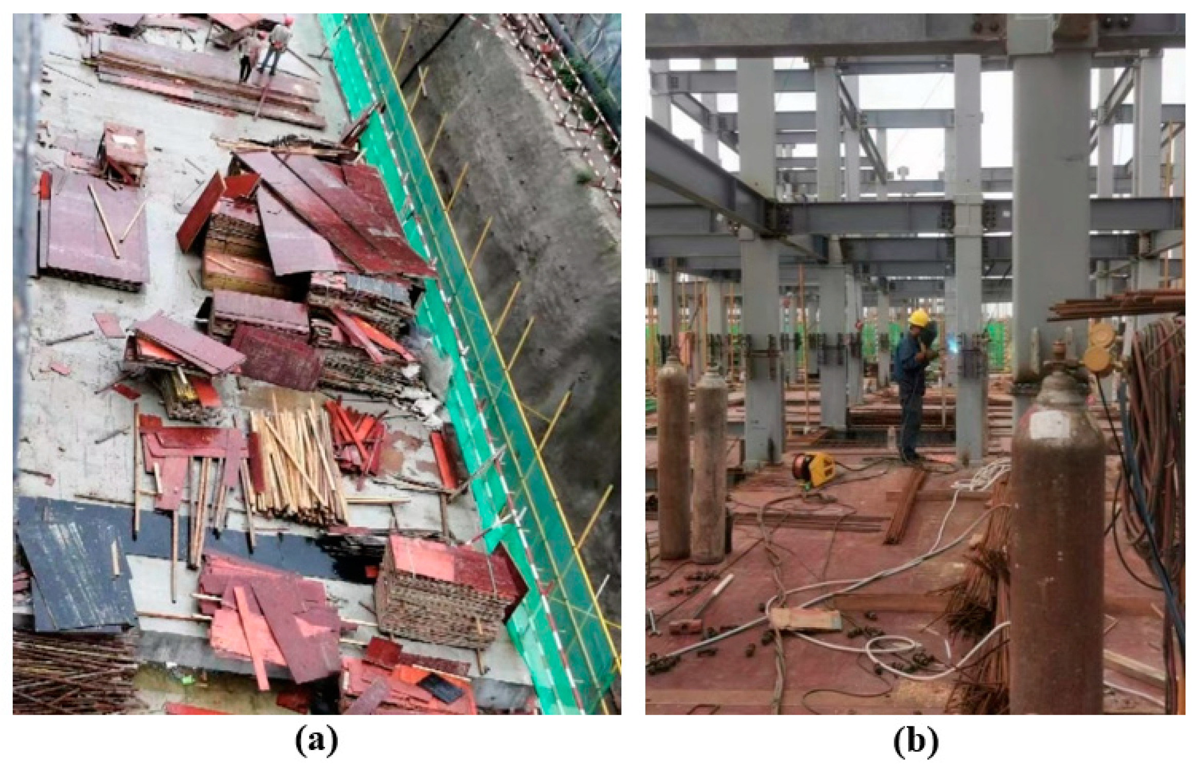
Foundation construction stage
During the foundation construction stage, fire prevention in the storage area of flammable materials should be focused on. For instance, attention should be paid to the fire monitoring in the woodworking shed where the wood board materials and flammable materials are stacked, as shown in Figure 9.
(2)
The main structure construction stage
During the main structure construction stage, monitoring devices should be set up in both flammable material areas (as shown in Figure 10a) and fire-using work areas (as shown in Figure 10b) to ensure that all areas at the construction area are within the monitoring range. Monitoring fire-use areas mainly includes: (i) welding places with open flame workload; (ii) the outer frame during operations such as steel welding and acetylene cutting; (iii) the lower layer during the construction of the upper layer when electric welding sparks may splash into the lower layer.
(3)
Decoration installation construction stage
At this stage, besides monitoring the places that are mentioned at the main structure construction stage, monitoring should be strengthened for storage places of flammable materials, such as paint and thermal insulation materials, as shown in Figure 11. These materials should be stored separately, while the storage place should be well ventilated to prevent flammable gases from burning and exploding.
Furthermore, the installation process of insulation boards should be specially monitored, as shown in Figure 12. Key points of this process include: (i) monitoring and prohibiting open flame operations and electrical welding operations around the working surface; (ii) monitoring electrical and wires of electric welding to prevent open circuits and sparks when installing pipelines; (iii) carefully monitoring the hidden dangers of static ignition and tool collision fire.

4.2. Visualization Functions

As illustrated in Section 2.2, the visualization subsystem can visually present the on-site situation, the entire process of a fire occurrence, and the evacuation route. The evacuation route should be first optimized by the escape route optimization subsystem and then presented to people by the visualization subsystem. Therefore, this section mainly presents the results of visualizing on-site information and fire scenes.

4.2.1. On-Site Information

The visualized on-site information at different places is shown in Figure 13. Note that the BIM model should be updated once new on-site information is collected by the monitoring devices.

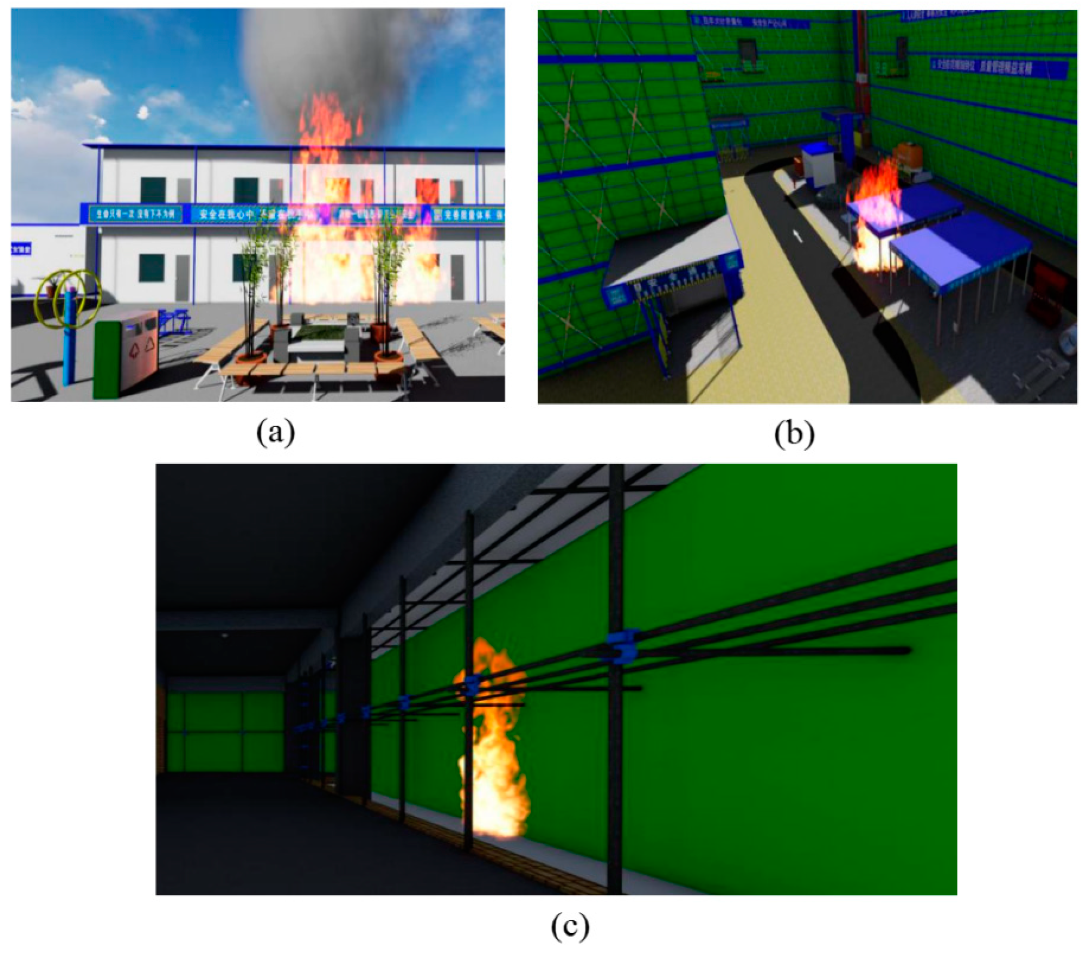
4.2.2. Fire Visualization

The fire visualization results at different places are shown in Figure 14. Note that in this study, fire visualization could only present the on-site fire situation. To predict and present the fire growth, integrating FDS into Revit can be used in this section. A detailed summary of this method is shown in Section 1.2. However, as the goal of this proposed system is to process an immediate solution for fire prevention at the construction site, the fire simulation function that may increase the response time is not considered in this study.

4.3. Escape Route Planning

The escape route optimization results of the reference case and the proposed optimization subsystem are listed in Table 4 and Table 5, respectively. Compared with the reference case, the proposed escape route subsystem has a higher escape time for some zones due to its ability to consider extra queuing time caused by people from previous zones. However, in this studied case, the escapeway selected for each zone by the proposed subsystem is the same as the reference case and t e s c a p e , t o t a l in both cases are the same, which is 1.69 min. The main reason is that the people count at the construction site is relatively small. Even if some zones may need extra queuing time, it would not affect the next zones’ escape because these queuing zones would pass through the escapeway before the next zones arrived.
However, if the people distribution at the construction site is more intensive in a certain area, the proposed system may select a different escapeway than the reference case. An example can be given by increasing the people count in Zone A and Zone B at each floor to be ten times their corresponding values shown in Table 3. Accordingly, the selected escapeways of different optimization methods are shown in Table 6. It shows that the proposed subsystem gives up the closest escapeway for Zone B on the second floor to the fourth floor, while the escapeway selected by the reference case is in line with the closest escapeway. This is because the proposed subsystem found that selecting a further exit for these zones would cause a faster evacuation than waiting to pass the closest escapeway. The proposed subsystem presents the strength to consider extra queuing time caused by congestion. However, it can also be further improved to consider the crowds on the staircases.

5. Conclusions and Future Works

This paper developed a novel BIM-based fire safety management platform for construction sites. It is composed of four subsystems: the fire visualization subsystem, the remote monitoring subsystem, the multi-stage fire alarm subsystem, and the escape route optimization subsystem. Besides ensuring the developed platform to consider the combination of BIM and construction site fire warnings, this study provides specific ideas for building this platform, which can be well suited to provide theoretical recommendations for future related research. In addition, the findings of this study have a relatively large potential for practical applications and will also provide guidelines for project managers and construction site managers of actual projects on managing fire prevention and warning management systems and developing corresponding management plans.
To achieve a realistic operation of this system, add-ins of these subsystems are developed for the Revit platform. Then, a case study is done to implement the proposed system. The main conclusions of this study are as follows: (1) The remote monitoring subsystem achieves an all-round monitoring of the fire status; (2) The BIM-based fire visualization subsystem vividly displays the on-site fire situation and timely presents the 3D drawing or animation of evacuation plans to people at the construction site. Due to the visualization feature of the BIM-based site model, people would be more familiar with on-site situations and evacuation routes; (3) The multi-stage fire alarm subsystem enables the managers at the construction site to carry out effective treatment measures according to the evaluated fire stage; (4) The escape route optimization subsystem shows the strength to consider the crowd at the construction site during evacuation. It effectively selects the escapeway with the shortest entire evacuation time and avoids the queuing at the closest escapeway. Thereby, the proposed system in this paper could provide informational and intellectual fire management services for different participants at the construction site, such as construction companies, equipment operation and maintenance companies, and labor companies.
In the future study, the proposed model will be validated and comprehensively analyzed based on some practical cases in different countries or regions and will also include the applicability to other building typologies, which will be a very prospective research solution for investigating the generalizability of this proposed system. Furthermore, future works could also focus on the following aspects: (i) considering the impact of design concepts on fire safety and fire conditions, such as fire smoke spread, the speed of evacuation, escape route optimization subsystems; (ii) considering the specific impact of weather and staircase crowding on the evacuation; (iii) comparing the proposed approach with traditional systems; to do this, the Charrette Test Method could be considered.

Author Contributions

Conceptualization, methodology, software, writing—original draft preparation, Y.Y.; conceptualization, methodology, software, writing—original draft preparation, Y.S.; methodology, software, writing—original draft preparation, M.C.; methodology, writing—review and editing, supervision, Y.Z.; methodology, writing—review and editing, supervision, R.W.; Conceptualization, methodology, software, writing—review and editing, supervision, Z.L. All authors have read and agreed to the published version of the manuscript.

Funding

This work was supported by the Hong Kong University of Science and Technology (Guangzhou) startup grant (G0101000059).

Institutional Review Board Statement

Not applicable.

Informed Consent Statement

Not applicable.

Data Availability Statement

No data are included.

Conflicts of Interest

The authors declare that they have no known competing financial interest or personal relationship that could have appeared to influence the work reported in this paper.

References

  1. El Meouche, R.; Abunemeh, M.; Hijazi, I.; Mebarki, A.; Fatayer, F.; Issa, A. Probabilistic Fire Risk Framework for Optimizing Construction Site Layout. Sustainability 2020, 12, 4065. [Google Scholar] [CrossRef]
  2. Kim, J.-S.; Kim, B.-S. Analysis of Fire-Accident Factors Using Big-Data Analysis Method for Construction Areas. KSCE J. Civ. Eng. 2018, 22, 1535–1543. [Google Scholar] [CrossRef]
  3. Shao, B.; Hu, Z.; Liu, Q.; Chen, S.; He, W. Fatal Accident Patterns of Building Construction Activities in China. Saf. Sci. 2019, 111, 253–263. [Google Scholar] [CrossRef]
  4. Vandecasteele, F.; Merci, B.; Verstockt, S. Fireground Location Understanding by Semantic Linking of Visual Objects and Building Information Models. Fire Saf. J. 2017, 91, 1026–1034. [Google Scholar] [CrossRef]
  5. Su, Y.; Mao, C.; Jiang, R.; Liu, G.; Wang, J. Data-Driven Fire Safety Management at Building Construction Sites: Leveraging CNN. J. Manag. Eng. 2021, 37, 04020108. [Google Scholar] [CrossRef]
  6. Chen, Y.-J.; Lai, Y.-S.; Lin, Y.-H. BIM-Based Augmented Reality Inspection and Maintenance of Fire Safety Equipment. Autom. Constr. 2020, 110, 103041. [Google Scholar] [CrossRef]
  7. Tsai, M.-K. Improving Efficiency in Emergency Response for Construction Site Fires: An Exploratory Case Study. J. Civ. Eng. Manag. 2016, 22, 322–332. [Google Scholar] [CrossRef]
  8. Wang, S.-H.; Wang, W.-C.; Wang, K.-C.; Shih, S.-Y. Applying Building Information Modeling to Support Fire Safety Management. Autom. Constr. 2015, 59, 158–167. [Google Scholar] [CrossRef]
  9. Khan, N.; Ali, A.K.; Van-Tien Tran, S.; Lee, D.; Park, C. Visual Language-Aided Construction Fire Safety Planning Approach in Building Information Modeling. Appl. Sci. 2020, 10, 1704. [Google Scholar] [CrossRef]
  10. Chen, H.; Hou, L.; Zhang, G.K.; Moon, S. Development of BIM, IoT and AR/VR Technologies for Fire Safety and Upskilling. Autom. Constr. 2021, 125, 103631. [Google Scholar] [CrossRef]
  11. Sun, Q.; Turkan, Y. A BIM-Based Simulation Framework for Fire Safety Management and Investigation of the Critical Factors Affecting Human Evacuation Performance. Adv. Eng. Inform. 2020, 44, 101093. [Google Scholar] [CrossRef]
  12. Kong, L.; Yang, Q.; Zhou, Q.; Xing, J.; Sun, X.; Zou, R. Embedding Knowledge into BIM: A Case Study of Extending BIM with Firefighting Plans. J. Build. Eng. 2022, 49, 103999. [Google Scholar] [CrossRef]
  13. Rüppel, U.; Schatz, K. Designing a BIM-Based Serious Game for Fire Safety Evacuation Simulations. Adv. Eng. Inform. 2011, 25, 600–611. [Google Scholar] [CrossRef]
  14. Cheng, M.-Y.; Chiu, K.-C.; Hsieh, Y.-M.; Yang, I.-T.; Chou, J.-S.; Wu, Y.-W. BIM Integrated Smart Monitoring Technique for Building Fire Prevention and Disaster Relief. Autom. Constr. 2017, 84, 14–30. [Google Scholar] [CrossRef]
  15. Chen, X.-S.; Liu, C.-C.; Wu, I.-C. A BIM-Based Visualization and Warning System for Fire Rescue. Adv. Eng. Inform. 2018, 37, 42–53. [Google Scholar] [CrossRef]
  16. Ma, G.; Wu, Z. BIM-Based Building Fire Emergency Management: Combining Building Users’ Behavior Decisions. Autom. Constr. 2020, 109, 102975. [Google Scholar] [CrossRef]
  17. Hosseini, O.; Maghrebi, M. Risk of Fire Emergency Evacuation in Complex Construction Sites: Integration of 4D-BIM, Social Force Modeling, and Fire Quantitative Risk Assessment. Adv. Eng. Inform. 2021, 50, 101378. [Google Scholar] [CrossRef]
  18. Siddiqui, A.A.; Ewer, J.A.; Lawrence, P.J.; Galea, E.R.; Frost, I.R. Building Information Modelling for Performance-Based Fire Safety Engineering Analysis—a Strategy for Data Sharing. J. Build. Eng. 2021, 102794. [Google Scholar] [CrossRef]
  19. Wang, L.; Li, W.; Feng, W.; Yang, R. Fire Risk Assessment for Building Operation and Maintenance Based on BIM Technology. Build. Environ. 2021, 25, 108188. [Google Scholar] [CrossRef]
  20. Shen, Q.; Wu, S.; Deng, Y.; Deng, H.; Cheng, J.C. BIM-Based Dynamic Construction Safety Rule Checking Using Ontology and Natural Language Processing. Buildings 2022, 12, 564. [Google Scholar] [CrossRef]
  21. Lovreglio, R.; Thompson, P.; Feng, Z. Automation in Fire Safety Engineering Using BIM and Generative Design. Fire Technol. 2022, 58, 1–5. [Google Scholar] [CrossRef]
  22. Shams Abadi, S.T.; Moniri Tokmehdash, N.; Hosny, A.; Nik-Bakht, M. BIM-Based Co-Simulation of Fire and Occupants’ Behavior for Safe Construction Rehabilitation Planning. Fire 2021, 4, 67. [Google Scholar] [CrossRef]
  23. Hasofer, A.M.; Odigie, D.O. Stochastic Modelling for Occupant Safety in a Building Fire. Fire Saf. J. 2001, 36, 269–289. [Google Scholar] [CrossRef]
  24. Benichou, N.; Kashef, A.H.; Reid, I.; Hadjisophocleous, G.V.; Torvi, D.A.; Morinville, G. FIERAsystem: A Fire Risk Assessment Tool to Evaluate Fire Safety in Industrial Buildings and Large Spaces. J. Fire Prot. Eng. 2005, 15, 145–172. [Google Scholar] [CrossRef]
  25. Hadjisophocleous, G.V.; Bénichou, N. Development of Performance-Based Codes, Performance Criteria and Fire Safety Engineering Methods. Int. J. Eng. Perform. Based Fire Codes 2000, 2, 127–142. [Google Scholar]
  26. Zhang, D.; Zhang, J.; Xiong, H.; Cui, Z.; Lu, D. Taking Advantage of Collective Intelligence and BIM-Based Virtual Reality in Fire Safety Inspection for Commercial and Public Buildings. Appl. Sci. 2019, 9, 5068. [Google Scholar] [CrossRef]
  27. Wong, M.O.; Zhou, H.; Ying, H.; Lee, S. A Voice-Driven IMU-Enabled BIM-Based Multi-User System for Indoor Navigation in Fire Emergencies. Autom. Constr. 2022, 135, 104137. [Google Scholar] [CrossRef]
  28. Li, N.; Becerik-Gerber, B.; Krishnamachari, B.; Soibelman, L. A BIM Centered Indoor Localization Algorithm to Support Building Fire Emergency Response Operations. Autom. Constr. 2014, 42, 78–89. [Google Scholar] [CrossRef]
  29. Tang, F.; Ren, A. Agent-Based Evacuation Model Incorporating Fire Scene and Building Geometry. Tsinghua Sci. Technol. 2008, 13, 708–714. [Google Scholar] [CrossRef]
  30. Shiau, Y.-C.; Tsai, Y.-Y.; Hsiao, J.-Y.; Chang, C.-T. Development of Building Fire Control and Management System in BIM Environment. Stud. Inf. Control. 2013, 22, 15–24. [Google Scholar] [CrossRef]
  31. Wu, W.; Lam, P.T.I.; Chew, D.A.S.; Li, Q.; Yam, M.C.H. Tracking of Safety Hazards and Real-Time-Prediction Model of Safety Risks on Construction Sites. Eng. Sci. 2010, 12, 68–72. [Google Scholar]
  32. Xu, Z.; Zhang, Z.; Lu, X.; Zeng, X.; Guan, H. Post-Earthquake Fire Simulation Considering Overall Seismic Damage of Sprinkler Systems Based on BIM and FEMA P-58. Autom. Constr. 2018, 90, 9–22. [Google Scholar] [CrossRef]
  33. Lotfi, N.; Behnam, B.; Peyman, F. A BIM-Based Framework for Evacuation Assessment of High-Rise Buildings under Post-Earthquake Fires. J. Build. Eng. 2021, 43, 102559. [Google Scholar] [CrossRef]
  34. Wang, T.; Du, M.H.; Tang, Y.F.; Zhang, Q. An Analysis on the Fire Model and the Safety Evacuation Based on BIM. Adv. Mater. Res. 2015, 1065–1069, 2386–2389. [Google Scholar] [CrossRef]
  35. Puttock, R. How to Keep Your Fire Detection System Healthy. Build. Eng. 2010, 85, 18–19. [Google Scholar]
  36. Kobes, M.; Helsloot, I.; de Vries, B.; Post, J.G. Building Safety and Human Behaviour in Fire: A Literature Review. Fire Saf. J. 2010, 45, 1–11. [Google Scholar] [CrossRef]
  37. Barbehenn, M. A Note on the Complexity of Dijkstra’s Algorithm for Graphs with Weighted Vertices. IEEE Trans. Comput. 1998, 47, 263. [Google Scholar] [CrossRef]
  38. Sabbaghzadeh, M.; Sheikhkhoshkar, M.; Talebi, S.; Rezazadeh, M.; Rastegar Moghaddam, M.; Khanzadi, M. A BIM-Based Solution for the Optimisation of Fire Safety Measures in the Building Design. Sustainability 2022, 14, 1626. [Google Scholar] [CrossRef]
  39. Pan, X.; Han, C.S.; Dauber, K.; Law, K.H. A Multi-Agent Based Framework for the Simulation of Human and Social Behaviors during Emergency Evacuations. AI Soc. 2007, 22, 113–132. [Google Scholar] [CrossRef]
  40. Pan, X.; Han, C.S.; Dauber, K.; Law, K.H. Human and Social Behavior in Computational Modeling and Analysis of Egress. Autom. Constr. 2006, 15, 448–461. [Google Scholar] [CrossRef]
  41. Zhang, S.; Teizer, J.; Lee, J.-K.; Eastman, C.M.; Venugopal, M. Building Information Modeling (BIM) and Safety: Automatic Safety Checking of Construction Models and Schedules. Autom. Constr. 2013, 29, 183–195. [Google Scholar] [CrossRef]
  42. Park, C.-S.; Kim, H.-J. A Framework for Construction Safety Management and Visualization System. Autom. Constr. 2013, 33, 95–103. [Google Scholar] [CrossRef]
  43. National Standard of the People’s Republic of China. Code for Fire Protection Design of Buildings; Singapore Civil Defence Force: Singapore, 2018.
  44. Hadjisophocleous, G.V.; Fu, Z. Literature Review of Fire Risk Assessment Methodologies. Int. J. Eng. Perform.Based Fire Codes 2004, 6, 28–45. [Google Scholar]
  45. Hernandez-Leal, P.A.; Arbelo, M.; Gonzalez-Calvo, A. Fire Risk Assessment Using Satellite Data. Adv. Space Res. 2006, 37, 741–746. [Google Scholar] [CrossRef]
  46. Chuvieco, E.; Aguado, I.; Yebra, M.; Nieto, H.; Salas, J.; Martín, M.P.; Vilar, L.; Martínez, J.; Martín, S.; Ibarra, P. Development of a Framework for Fire Risk Assessment Using Remote Sensing and Geographic Information System Technologies. Ecol. Model. 2010, 221, 46–58. [Google Scholar] [CrossRef]
Figure 1. Revit add-ins of subsystems.
Buildings 12 01268 g001
Figure 2. Operation process of the BIM-based fire safety management system.
Buildings 12 01268 g002
Figure 3. Example of components in the monitoring system of the remote monitoring subsystem.
Buildings 12 01268 g003
Figure 4. Control process of the control system in the remote monitoring subsystem.
Buildings 12 01268 g004
Figure 5. Example of components in the control system of the remote monitoring subsystem.
Buildings 12 01268 g005
Figure 6. Schematic of the multi-stage fire alarm subsystem.
Buildings 12 01268 g006
Figure 7. A 3D schematic of the studied education building.
Buildings 12 01268 g007
Figure 8. Fire situation on the first floor.
Buildings 12 01268 g008
Figure 9. Monitoring scene of a woodworking shed.
Buildings 12 01268 g009
Figure 10. Monitoring scene during the main structure construction stage at (a) a flammable material stack area and (b) a fire-using work area.
Buildings 12 01268 g010
Figure 11. The storage places of paint and thermal insulation materials.
Buildings 12 01268 g011
Figure 12. The installation process of insulation boards.
Buildings 12 01268 g012
Figure 13. Visualized on-site information at different places. (a) Woodworking shed. (b) Steel bar processing shed. (c) Construction area. (d) Flammable material storage room. (e) Canteen. (f) Dormitory.
Buildings 12 01268 g013
Figure 14. Fire visualization at: (a) living area; (b) flammable material area; (c) scaffold.
Buildings 12 01268 g014
Table 1. Fire stages in the multi-stage fire alarm subsystem.
StagesDefinition
Stage 1Smoke detectors in a certain area start alarming at temperatures > 40 °C.
Stage 2Smoke detectors in that certain area keep alarming for more than 3 min or at temperatures > 43 °C.
Stage 3All smoke detectors in a larger area start alarming at temperatures > 45 °C.
Table 2. Characteristics of the studied education building.
Building TypeBuilding StoryBuilding ScaleFire-Resistant Level
(Above/Underground)
SERVICE LIFESeismic Fortification Intensity
Education buildingMultistorySmallSecond/-50Grade 7
Main structureRoof waterproof levelNo. of stories
(Above/underground)
Height
(m)
Land area (m2)Building area above ground (m2)
FrameI4/018.0018006700
Table 3. Information for each zone.
ZoneNumber of PeopleDistance to Escapeway 1, mDistance to Escapeway 2, m
Zone A (First floor)730110
Zone B (First floor)94595
Zone C (First floor)27070
Zone D (First floor)910040
Zone E (First floor)513010
Zone A (Second floor)640120
Zone B (Second floor)655105
Zone C (Second floor)18080
Zone D (Second floor)411050
Zone E (Second floor)314020
Zone A (Third floor)350130
Zone B (Third floor)465115
Zone C (Third floor)79090
Zone D (Third floor)512060
Zone E (Third floor)615030
Zone A (Fourth floor)360140
Zone B (Fourth floor)275125
Zone C (Fourth floor)6100100
Zone D (Fourth floor)213070
Zone E (Fourth floor)316040
Table 4. Escape route optimization results of the reference case.
Escapeway 1Escapeway 2EscapeWayOptimized tescape,itescape,total
Zonettravel,itqueue,itescape,ittravel,itqueue,itescape,i
Zone A (First floor)0.50 0.04 0.54 1.83 0.03 1.86 10.54 1.69
Zone B (First floor)0.75 0.05 0.80 1.58 0.03 1.62 10.80
Zone C (First floor)1.17 0.01 1.18 1.17 0.01 1.17 21.17
Zone D (First floor)1.67 0.05 1.72 0.67 0.03 0.70 20.70
Zone E (First floor)2.17 0.03 2.19 0.17 0.02 0.19 20.19
Zone A (Second floor)0.67 0.03 0.70 2.00 0.02 2.02 10.70
Zone B (Second floor)0.92 0.03 0.95 1.75 0.02 1.77 10.95
Zone C (Second floor)1.33 0.01 1.34 1.33 0.00 1.34 21.34
Zone D (Second floor)1.83 0.02 1.86 0.83 0.01 0.85 20.85
Zone E (Second floor)2.33 0.02 2.35 0.33 0.01 0.34 20.34
Zone A (Third floor)0.83 0.02 0.85 2.17 0.01 2.18 10.85
Zone B (Third floor)1.08 0.02 1.11 1.92 0.01 1.93 11.11
Zone C (Third floor)1.50 0.04 1.54 1.50 0.03 1.53 21.53
Zone D (Third floor)2.00 0.03 2.03 1.00 0.02 1.02 21.02
Zone E (Third floor)2.50 0.03 2.53 0.50 0.02 0.52 20.52
Zone A (Fourth floor)1.00 0.02 1.02 2.33 0.01 2.34 11.02
Zone B (Fourth floor)1.25 0.01 1.26 2.08 0.01 2.09 11.26
Zone C (Fourth floor)1.67 0.08 1.70 1.67 0.02 1.69 21.69
Zone D (Fourth floor)2.17 0.04 2.18 1.17 0.01 1.17 21.17
Zone E (Fourth floor)2.67 0.02 2.68 0.67 0.04 0.68 20.68
Table 5. Escape route optimization results of the proposed system.
Escapeway 1Escapeway 2EscapeWayOptimized tescape,itescape,total
Zonettravel,itqueue,itescape,ittravel,itqueue,itescape,i
Zone A (First floor)0.500.040.541.830.031.8610.54 1.69
Zone B (First floor)0.750.050.801.580.031.6210.80
Zone C (First floor)1.170.011.181.170.011.1721.17
Zone D (First floor)1.670.051.720.670.030.7020.70
Zone E (First floor)2.170.032.190.170.020.1920.19
Zone A (Second floor)0.670.030.702.000.022.0210.70
Zone B (Second floor)0.920.030.951.750.021.7710.95
Zone C (Second floor)1.330.011.341.330.001.3421.34
Zone D (Second floor)1.830.021.860.830.010.8520.85
Zone E (Second floor)2.330.022.350.330.010.3420.34
Zone A (Third floor)0.830.020.852.170.012.1810.85
Zone B (Third floor)1.080.021.111.920.011.9311.11
Zone C (Third floor)1.500.041.541.500.031.5321.53
Zone D (Third floor)2.000.032.031.000.021.0221.02
Zone E (Third floor)2.500.032.530.500.020.5220.52
Zone A (Fourth floor)1.000.021.022.330.012.3411.02
Zone B (Fourth floor)1.250.011.262.080.012.0911.26
Zone C (Fourth floor)1.670.081.751.670.021.6921.69
Zone D (Fourth floor)2.170.042.211.170.011.1821.18
Zone E (Fourth floor)2.670.022.680.670.040.7120.71
Table 6. Selected escapeway when increasing the people count for Zone A and Zone B.
ZoneNumber of PeopleDistance to
Escapeway 1, m
Distance to
Escapeway 2, m
Selected Escapeway
ClosestReference CaseProposed Subsystem
Zone A (First floor)7030110111
Zone B (First floor)904595111
Zone C (First floor)27070222
Zone D (First floor)910040222
Zone E (First floor)513010222
Zone A (Second floor)6040120111
Zone B (Second floor)6055105112
Zone C (Second floor)18080222
Zone D (Second floor)411050222
Zone E (Second floor)314020222
Zone A (Third floor)3050130111
Zone B (Third floor)4065115112
Zone C (Third floor)79090222
Zone D (Third floor)512060222
Zone E (Third floor)615030222
Zone A (Fourth floor)3060140111
Zone B (Fourth floor)2075125112
Zone C (Fourth floor)6100100222
Zone D (Fourth floor)213070222
Zone E (Fourth floor)316040222
Publisher’s Note: MDPI stays neutral with regard to jurisdictional claims in published maps and institutional affiliations.

