
Combined Effects of Sulfate and Chloride Attack on Steel Reinforced Mortar under Drying–Immersion Cycles

 , ,
, ,
Abstract
:1. Introduction
2. Materials and Methods
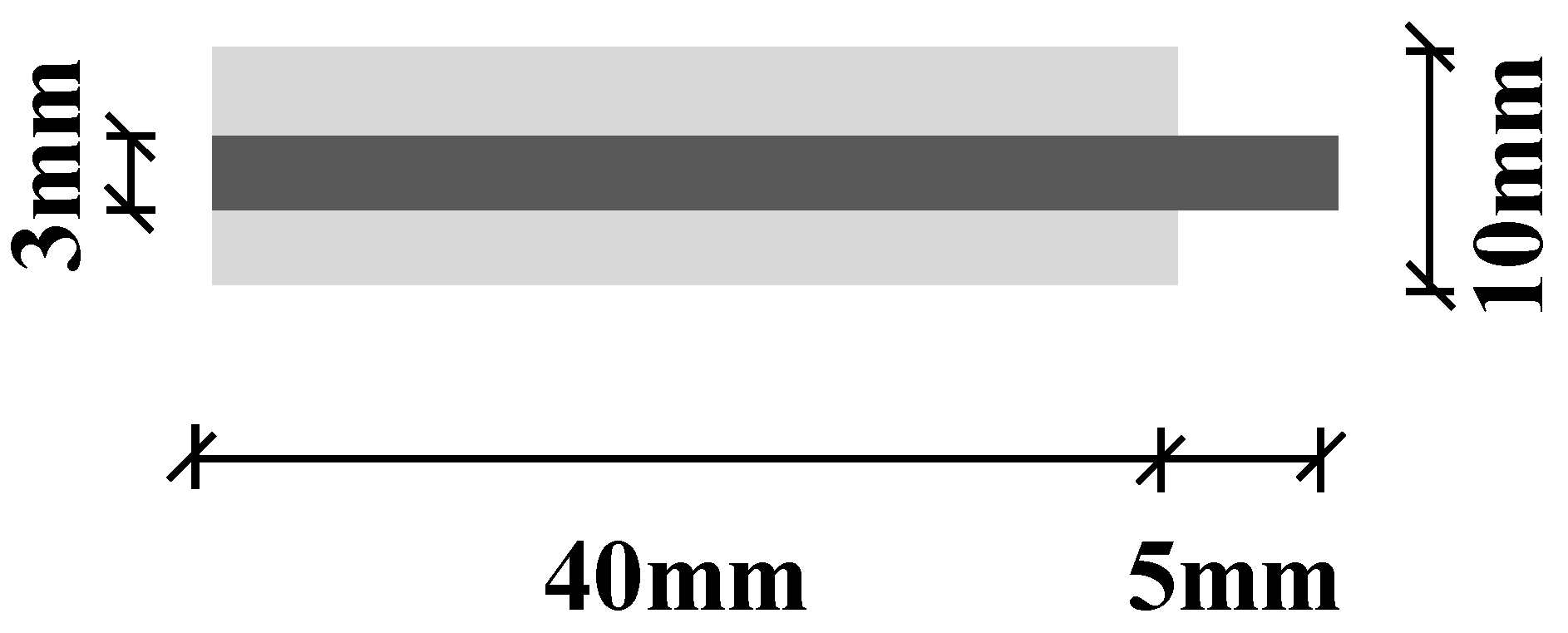
2.1. Materials and Specimen Preparation
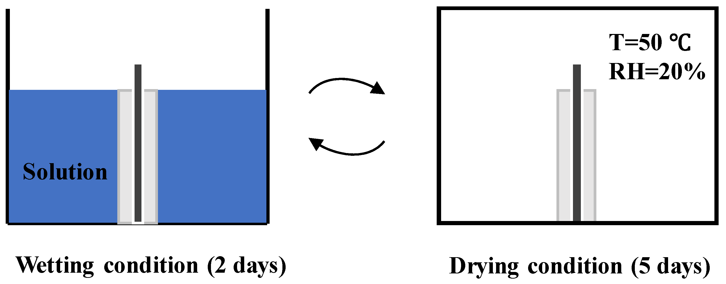
2.2. Setting of Drying–Immersion Cycles
2.3. Testing
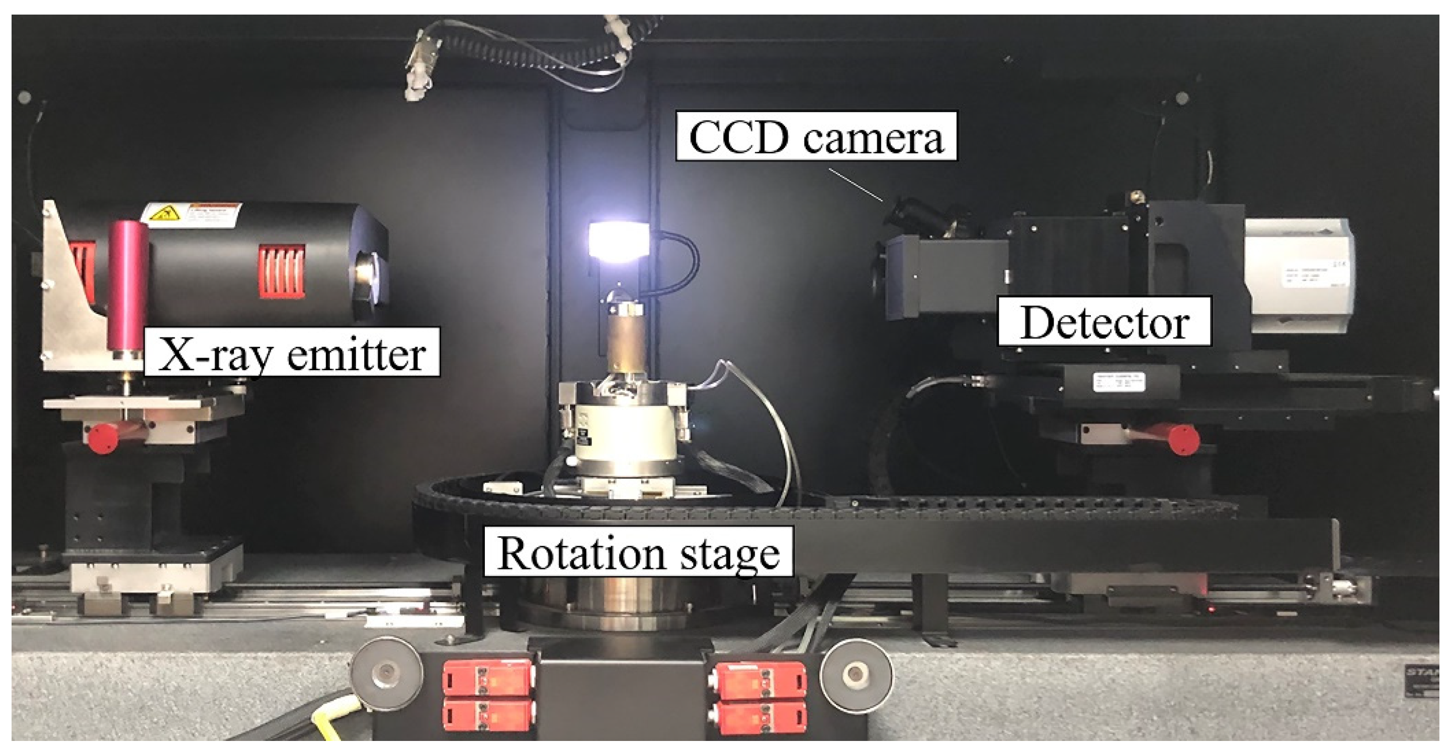
2.3.1. XCT Testing
2.3.2. BSE-SEM
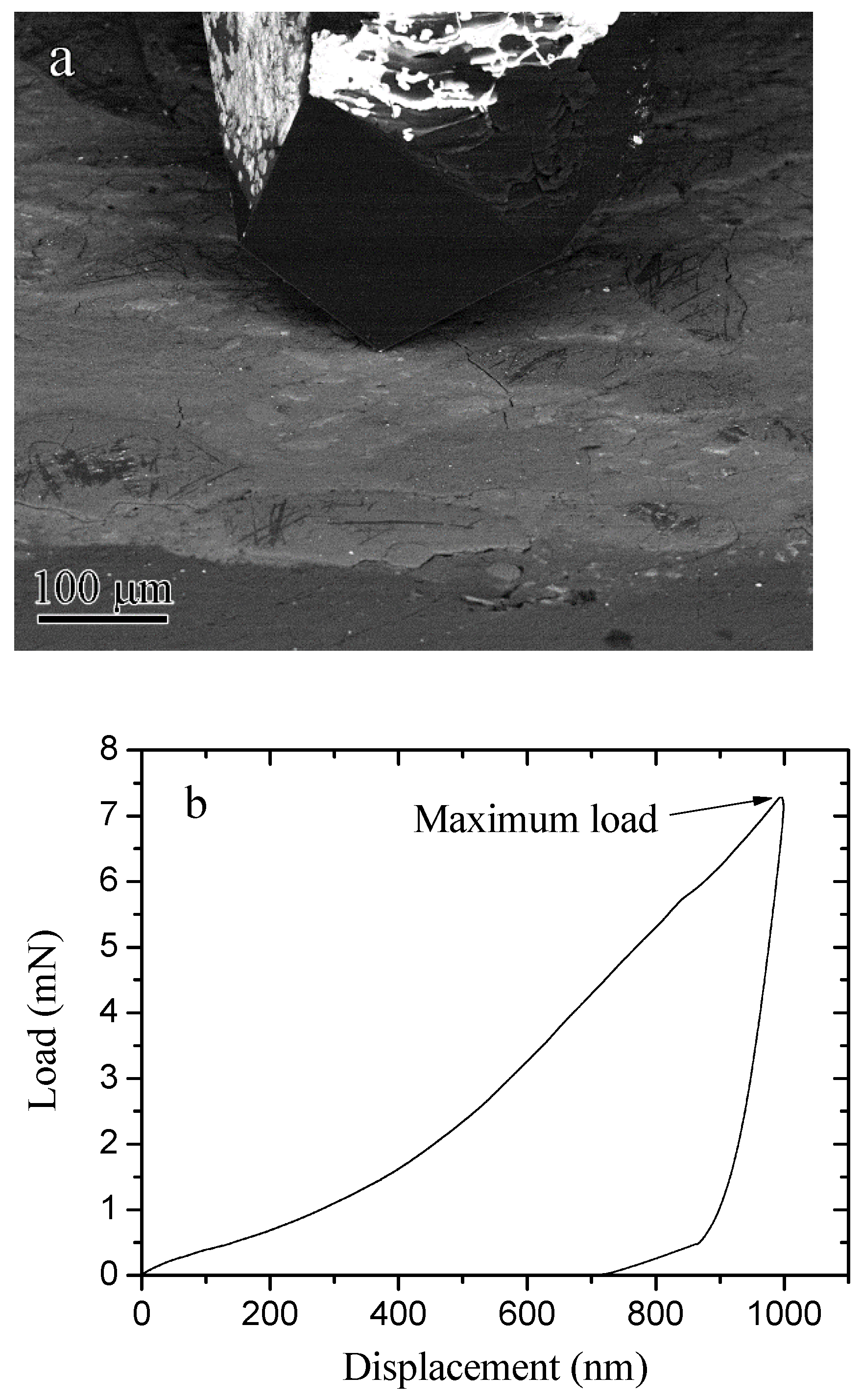
2.3.3. Nanoindentation in SEM
3. Results and Discussion
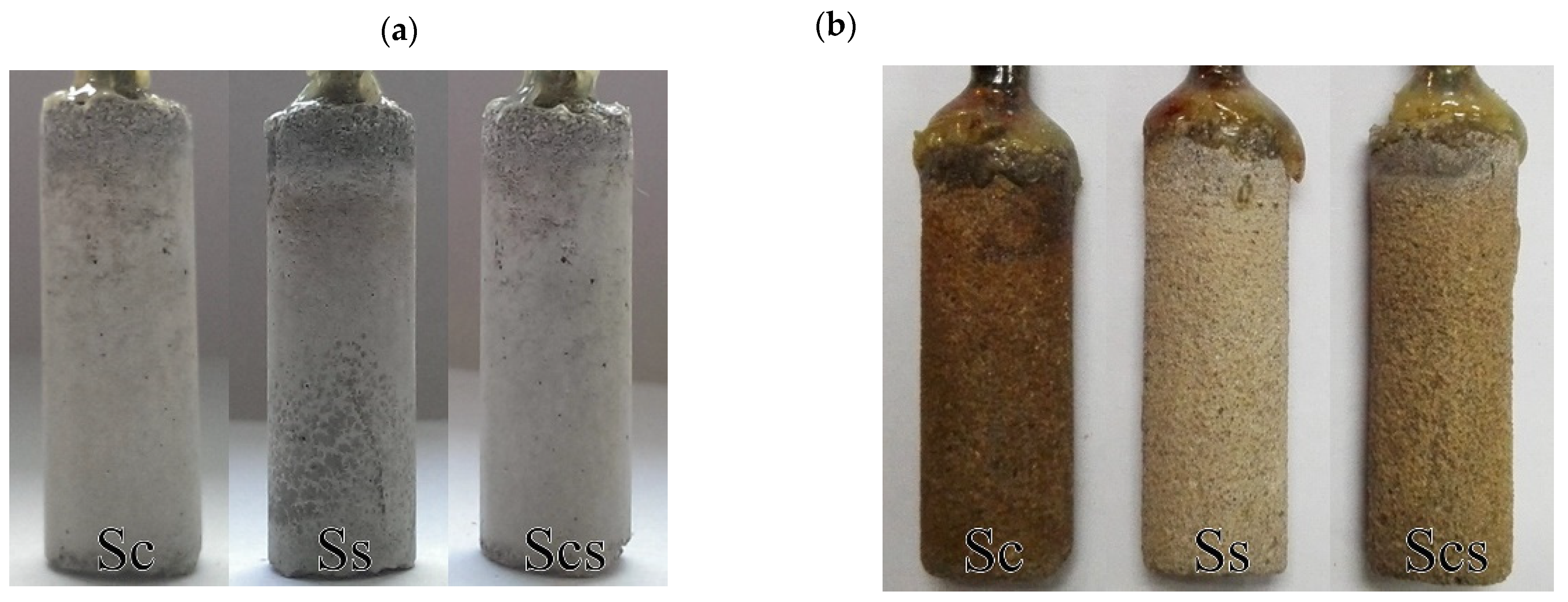
3.1. Influence on Steel Reinforcement
3.2. Influence on Mortar Cover
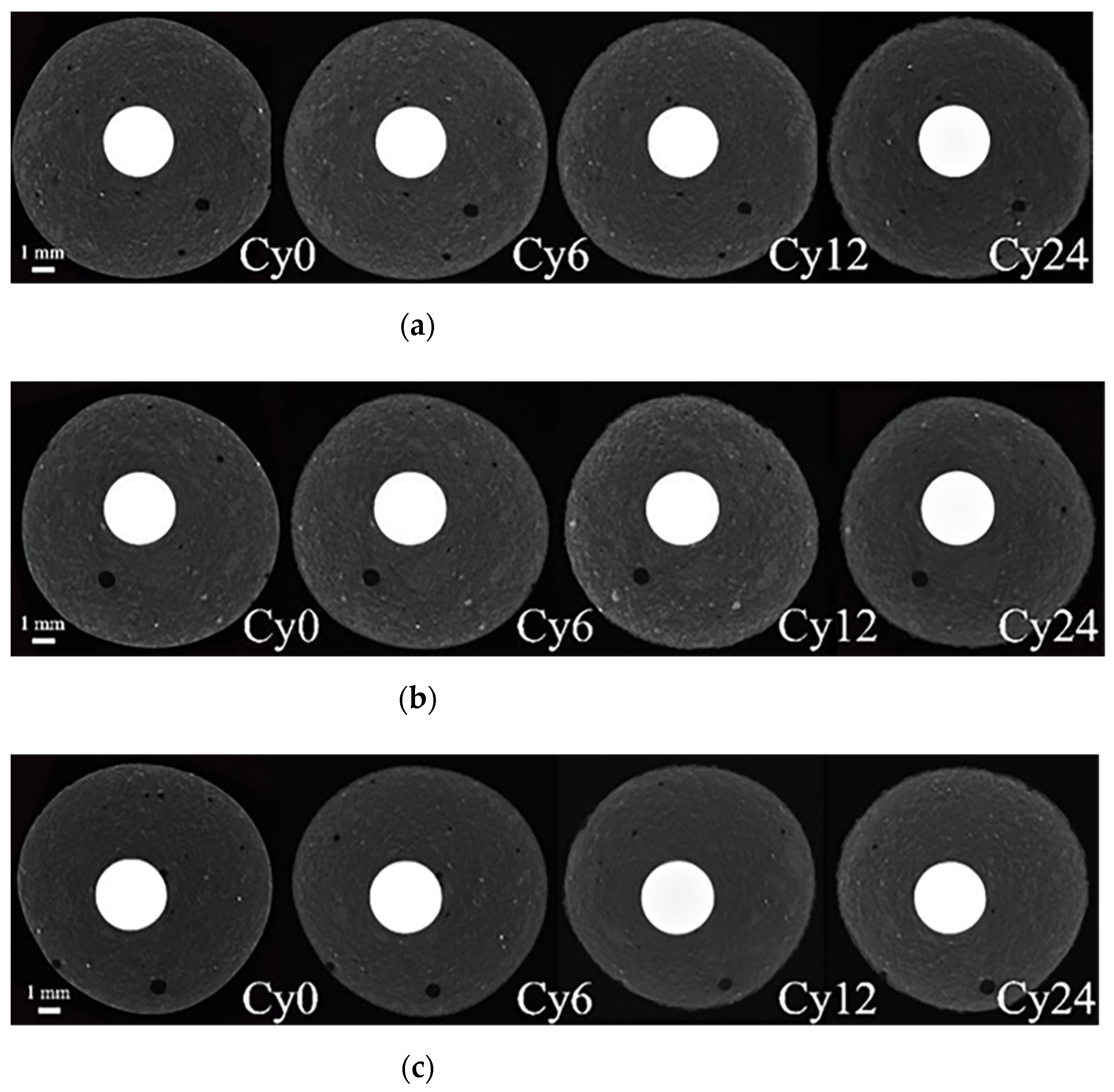
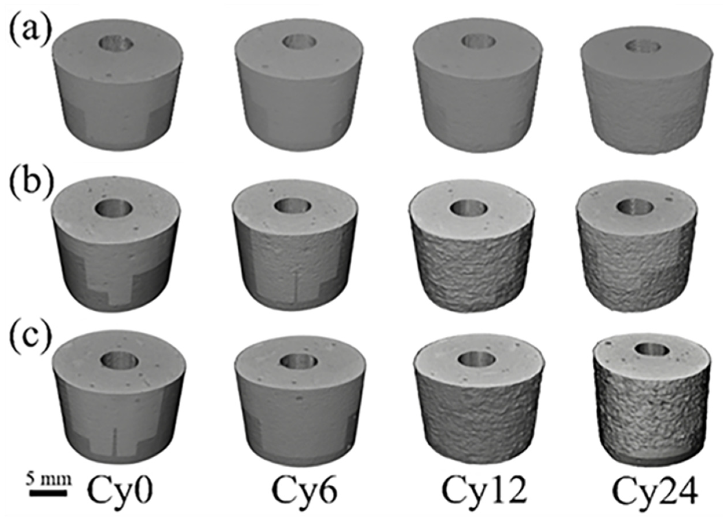
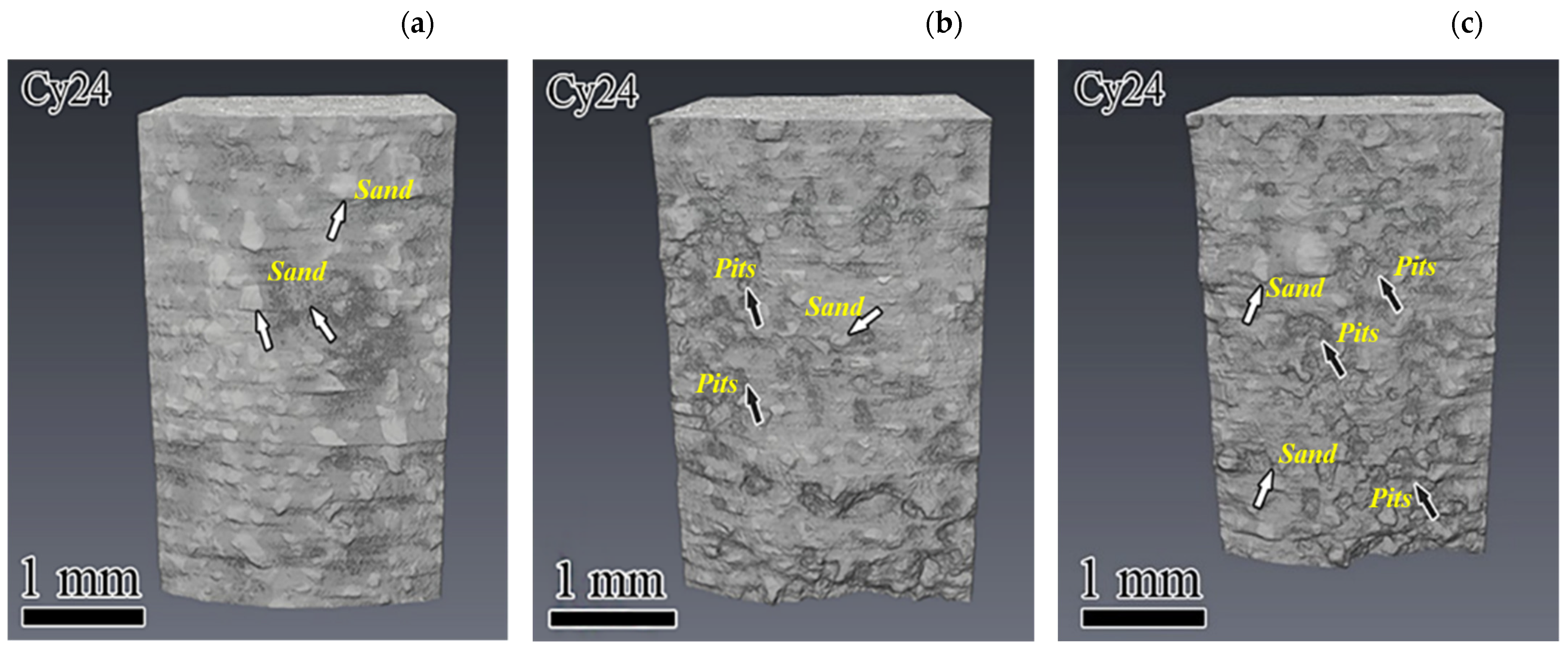
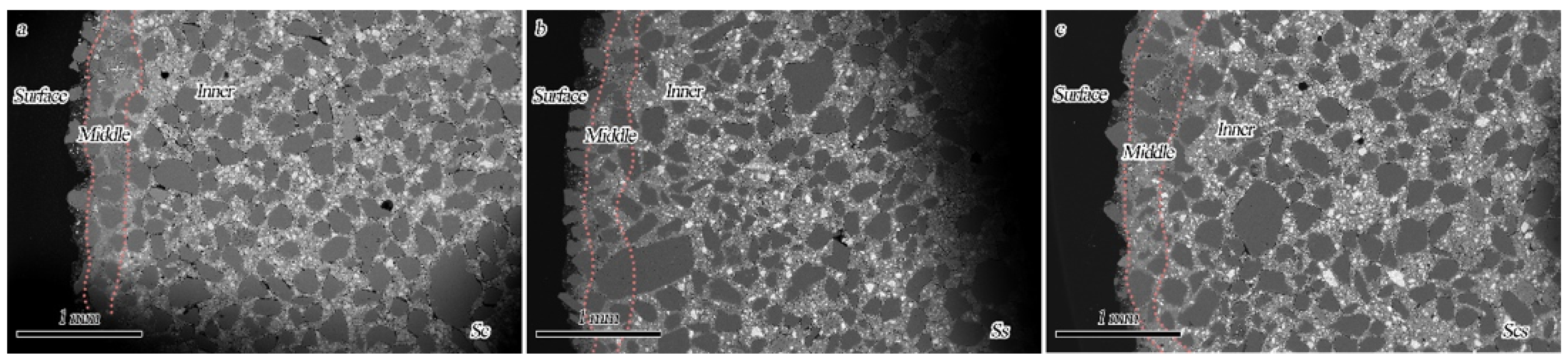
3.2.1. Qualitative Analysis
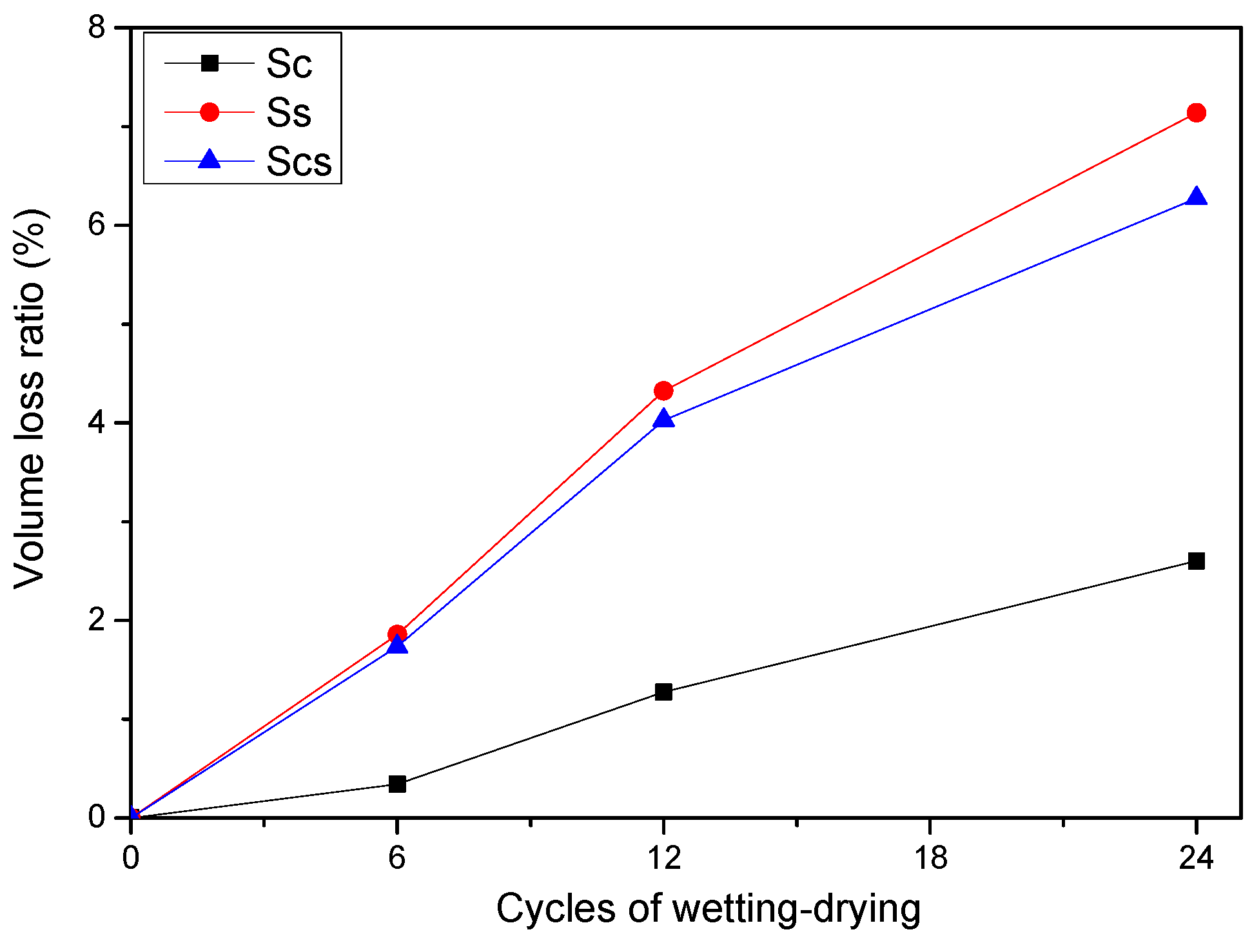
3.2.2. Quantitative Analysis
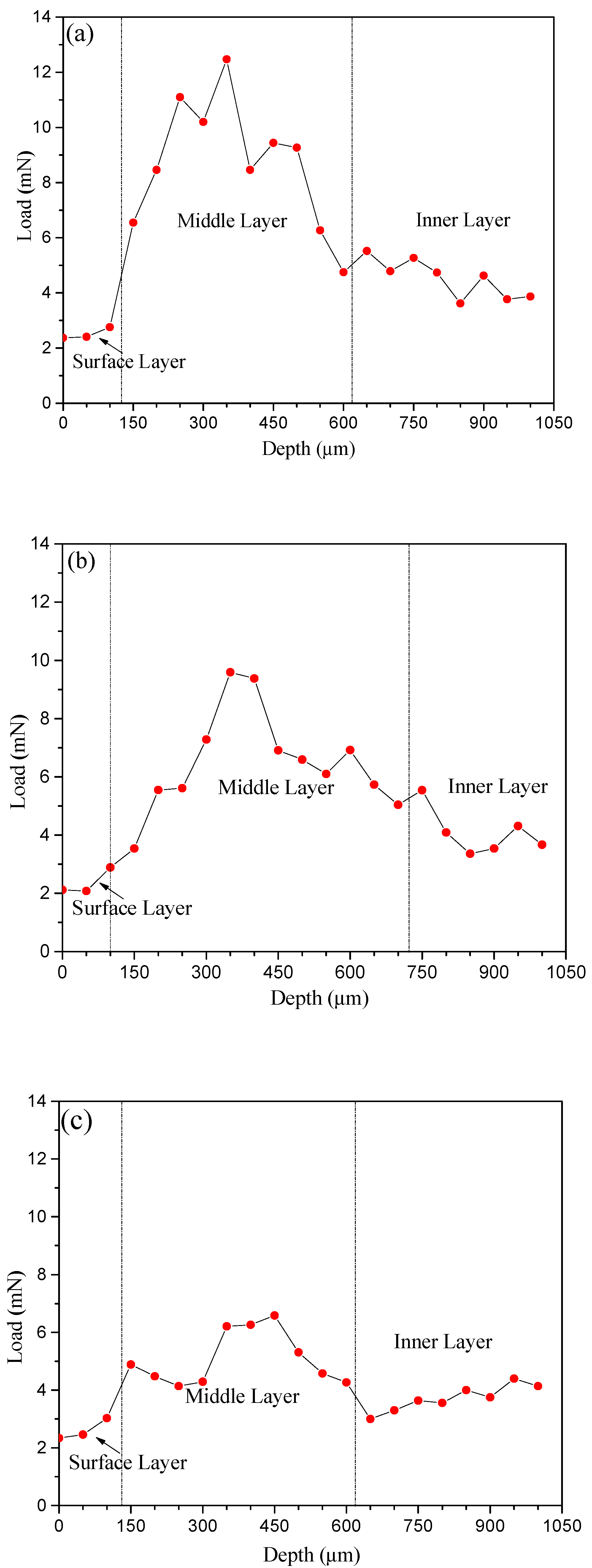
3.2.3. Micro-Mechanic Analysis
4. Conclusions
- (1).
- In terms of steel corrosion, chloride caused much more severe corrosion to steel than did the sulfate solution. For the specimen immersed in the combined solution (Scs), the existence of sulfate suppressed the steel corrosion caused by chloride. By investigating the damage on mortar cover, it was found that the sulfate caused much more damage to mortar covers than chloride did, likely due to the formation of expansive ettringite.
- (2).
- After 24 drying–immersion cycles, the volume loss of specimens immersed in the sulfate solution were the highest (~7.1%), followed by those for the specimens exposed to the combined chloride and sulfate solution Scs (~6.3%), indicating that the presence of chloride suppressed the sulfate attack although this effect was not significant. The lowest volume loss of specimens occurred when they were immersed in the chloride solution (~2.6%). The competitive nature of chloride and sulfate was confirmed based on both qualitative and quantitative analyses.
- (3).
- The degradation of mortars was found to be a layer-dependent process. The mechanical properties of all specimens decreased in the sequence of surface layer, inner layer, then middle layer since the middle layer obtained the most compact microstructure. Moreover, the mechanical strength of the middle layer increased in the following sequence (Scs < Ss < Sc), indicating that the total ion concentration would affect the performance (such as strength) of a local area due to the more remarkable physical salt crystallization than to chemical reactions (such as the leaching effect, hydration rate, etc.). However, the final degradation rate indicated by the surface shedding and volume loss of specimens was still dominated by chemical attack. For the surface and inner layers, the corresponding micro-mechanical strength appeared not to be significantly influenced by external solutions.
Author Contributions
Funding
Institutional Review Board Statement
Informed Consent Statement
Data Availability Statement
Conflicts of Interest
References
- Maes, M.; De Belie, N. Resistance of concrete and mortar against combined attack of chloride and sodium sulphate. Cem. Concr. Compos. 2014, 53, 59–72. [Google Scholar] [CrossRef]
- Liu, G.J.; Zhang, Y.S.; Ni, Z.W.; Huang, R. Corrosion behavior of steel submitted to chloride and sulphate ions in simulated concrete pore solution. Constr. Build. Mater. 2016, 115, 1–5. [Google Scholar] [CrossRef]
- Ying, G.G.; Song, C.; Ren, J.; Guo, S.-Y.; Nie, R.; Zhang, L. Mechanical and durability-related performance of graphene/epoxy resin and epoxy resin enhanced OPC mortar. Constr. Build. Mater. 2021, 282, 122644. [Google Scholar] [CrossRef]
- Sun, H.; Wu, W.; Zhao, Y.; Lin, Y.; Xu, S.; Zhang, T.; Zhang, X.; Xing, F.; Ren, J. Mechanical and durability properties of blended OPC mortar modified by low-carbon belite (C2S) nanoparticles. J. Clean. Prod. 2021, 305, 127087. [Google Scholar] [CrossRef]
- Hekal, E.E.; Kishar, E.; Mostafa, H. Magnesium sulfate attack on hardened blended cement pastes under different circumstances. Cem. Concr. Res. 2002, 32, 1421–1427. [Google Scholar] [CrossRef]
- Liu, P.; Chen, Y.; Wang, W.; Yu, Z. Effect of physical and chemical sulfate attack on performance degradation of concrete under different conditions. Chem. Phys. Lett. 2020, 745, 137254. [Google Scholar] [CrossRef]
- Sotiriadis, K.; Rakanta, E.; Mitzithra, M.E.; Batis, G.; Tsivilis, S. Influence of Sulfates on Chloride Diffusion and Chloride-Induced Reinforcement Corrosion in Limestone Cement Materials at Low Temperature. J. Mater. Civ. Eng. 2017, 29, 12. [Google Scholar] [CrossRef]
- Zuquan, J.; Wei, S.; Yunsheng, Z.; Jinyang, J.; Jianzhong, L. Interaction between sulfate and chloride solution attack of concretes with and without fly ash. Cem. Concr. Res. 2007, 37, 1223–1232. [Google Scholar] [CrossRef]
- Chen, Z.; Wu, L.Y.; Bindiganavile, V.; Yi, C.F. Coupled models to describe the combined diffusion-reaction behaviour of chloride and sulphate ions in cement-based systems. Constr. Build. Mater. 2020, 243, 13. [Google Scholar] [CrossRef]
- Xu, F.; Yang, Z.Q.; Liu, W.Q.; Wang, S.G.; Zhang, H.G. Experimental investigation on the effect of sulfate attack on chloride diffusivity of cracked concrete subjected to composite solution. Constr. Build. Mater. 2020, 237, 9. [Google Scholar] [CrossRef]
- Douglas Hooton, R. Current developments and future needs in standards for cementitious materials. Cem. Concr. Res. 2015, 78, 165–177. [Google Scholar] [CrossRef]
- Harrison, W.H. Effect of chloride in mix ingredients on sulphate resistance of concrete. Mag. Concr. Res. 1990, 42, 113–126. [Google Scholar] [CrossRef]
- Maslehuddin, M.; Page, C.L.; Rasheeduzzafar. Temperature effect on the pore solution chemistry in contaminated cements. Mag. Concr. Res. 1997, 49, 5–14. [Google Scholar] [CrossRef]
- Zhao, G.W.; Li, J.P.; Shi, M.; Cui, J.F.; Xie, F. Degradation of cast-in-situ concrete subjected to sulphate-chloride combined attack. Constr. Build. Mater. 2020, 241, 10. [Google Scholar] [CrossRef]
- Zhutovsky, S.; Kovler, K. Effect of internal curing on durability-related properties of high performance concrete. Cem. Concr. Res. 2012, 42, 20–26. [Google Scholar] [CrossRef]
- Alkaysi, M.; El-Tawil, S.; Liu, Z.C.; Hansen, W. Effects of silica powder and cement type on durability of ultra high performance concrete (UHPC). Cem. Concr. Compos. 2016, 66, 47–56. [Google Scholar] [CrossRef]
- Li, Y.L.; Zhao, X.L.; Raman, R.K.S. Mechanical properties of seawater and sea sand concrete-filled FRP tubes in artificial seawater. Constr. Build. Mater. 2018, 191, 977–993. [Google Scholar] [CrossRef]
- Zhou, Z.D.; Qiao, P.Z. Durability of ultra-high performance concrete in tension under cold weather conditions. Cem. Concr. Compos. 2018, 94, 94–106. [Google Scholar] [CrossRef]
- Myers, R.J.; Bernal, S.A.; Nicolas, R.S.; Provis, J.L. Generalized Structural Description of Calcium–Sodium Aluminosilicate Hydrate Gels: The Cross-Linked Substituted Tobermorite Model. Langmuir 2013, 29, 5294–5306. [Google Scholar] [CrossRef]
- Itty, P.A.; Serdar, M.; Meral, C.; Parkinson, D.; MacDowell, A.A.; Bjegovic, D.; Monteiro, P.J.M. In situ 3D monitoring of corrosion on carbon steel and ferritic stainless steel embedded in cement paste. Corros. Sci. 2014, 83, 409–418. [Google Scholar] [CrossRef]
- Xi, X.; Yang, S.T. Investigating the spatial development of corrosion of corner-located steel bar in concrete by X-ray computed tomography. Constr. Build. Mater. 2019, 221, 177–189. [Google Scholar] [CrossRef]
- Zhou, Y.W.; Zheng, B.W.; Sui, L.L.; Xing, F.; Li, P.D.; Sun, H.F. Effects of external confinement on steel reinforcement corrosion products monitored by X-ray microcomputer tomography. Constr. Build. Mater. 2019, 222, 531–543. [Google Scholar] [CrossRef]
- Gautham, S.; Sindu, B.S.; Sasmal, S. Evaluation of the phase properties of hydrating cement composite using simulated nanoindentation technique. Model. Simul. Mater. Sci. Eng. 2017, 25, 22. [Google Scholar] [CrossRef]
- Constantinides, G.; Ulm, F.J. The effect of two types of C-S-H on the elasticity of cement-based materials: Results from nanoindentation and micromechanical modeling. Cem. Concr. Res. 2004, 34, 67–80. [Google Scholar] [CrossRef]
- Kumar, V. Protection of steel reinforcement for concrete—A review. Corros. Rev. 1998, 16, 317–358. [Google Scholar] [CrossRef]
- Sorelli, L.; Constantinides, G.; Ulm, F.J.; Toutlemonde, F. The nano-mechanical signature of Ultra High Performance Concrete by statistical nanoindentation techniques. Cem. Concr. Res. 2008, 38, 1447–1456. [Google Scholar] [CrossRef]
- Moser, R.D.; Allison, P.G.; Chandler, M.Q. Characterization of Impact Damage in Ultra-High Performance Concrete Using Spatially Correlated Nanoindentation/SEM/EDX. J. Mater. Eng. Perform. 2013, 22, 3902–3908. [Google Scholar] [CrossRef]
- Cheng, S.; Shui, Z.; Gao, X.; Yu, R.; Sun, T.; Guo, C.; Huang, Y. Degradation mechanisms of Portland cement mortar under seawater attack and drying-immersion cycles. Constr. Build. Mater. 2020, 230, 116934. [Google Scholar] [CrossRef]
- Zhang, X.; Jiang, C.; Chen, Y.; Yuan, B.; Memon, S.A.; Ren, J.; Xing, F.; Sun, H. Influence of initial defects on the degradation of steel reinforced mortar exposed to cyclic wetting and drying environment based on 3D scanning. Constr. Build. Mater. 2022, 325, 126591. [Google Scholar] [CrossRef]
- Ren, J.; Guo, S.; Su, J.; Zhao, T.; Chen, J.; Zhang, S. A novel TiO2/Epoxy resin composited geopolymer with great durability in wetting-drying and phosphoric acid solution. J. Clean. Prod. 2019, 227, 849–860. [Google Scholar] [CrossRef]
- Chen, Y.; Gao, J.; Tang, L.; Li, X. Resistance of concrete against combined attack of chloride and sulfate under drying–wetting cycles. Constr. Build. Mater. 2016, 106, 650–658. [Google Scholar] [CrossRef]
- Sun, H.; Liu, S.; Cao, K.; Yu, D.; Memon, S.A.; Liu, W.; Zhang, X.; Xing, F.; Zhao, D. Degradation mechanism of cement mortar exposed to combined sulfate–chloride attack under cyclic wetting–drying condition. Mater. Struct. 2021, 54, 138. [Google Scholar] [CrossRef]
- Gb/t3274-2017; Hot-Rolled Plates and Strips of Carbon Structural Steels and High Strength Low Alloy Structural Steels. Standards Press of China: Beijing, China, 2017.
- Gb/t17671-1999; Method of Testing Cements—Determination of Strength. Chinese Standards Institute: Beijing, China, 1999.
- Sun, H.; Liu, S.; Yu, F.; Zhang, X.; Wu, C.; Xing, F.; Ren, J. Behaviour of cement binder exposed to semi-immersion in chloride-rich salt solutions and seawater with different RH levels. Cem. Concr. Compos. 2022, 131, 104606. [Google Scholar] [CrossRef]
- Zhang, M.H.; Chen, J.K.; Lv, Y.F.; Wang, D.J.; Ye, J. Study on the expansion of concrete under attack of sulfate and sulfate-chloride ions. Constr. Build. Mater. 2013, 39, 26–32. [Google Scholar] [CrossRef]
- Luo, S.; Zhao, M.; Jiang, Z.; Liu, S.; Yang, L.; Mao, Y.; Pan, C. Microwave preparation and carbonation properties of low-carbon cement. Constr. Build. Mater. 2022, 320, 126239. [Google Scholar] [CrossRef]
- Glasser, F.P.; Marchand, J.; Samson, E. Durability of concrete—Degradation phenomena involving detrimental chemical reactions. Cem. Concr. Res. 2008, 38, 226–246. [Google Scholar] [CrossRef]
- Cohen, M.D.; Mather, B. Sulfate Attack on Concrete—Research Needs. Aci. Mater. J. 1991, 88, 62–69. [Google Scholar]
- Thaulow, N.; Sahu, S. Mechanism of concrete deterioration due to salt crystallization. Mater. Charact. 2004, 53, 123–127. [Google Scholar] [CrossRef]


| Element | C | Si | Mn | P | S | N | Cr | Cu | Ni | Fe |
|---|---|---|---|---|---|---|---|---|---|---|
| Mass fraction | 0.09 | 0.03 | 0.42 | 0.02 | 0.02 | 0.005 | ≤0.02 | 0.04 | ≤0.3 | Bal. |
| Oxides. | Content (wt.%) |
|---|---|
| SiO2 | 21.20 |
| Al2O3 | 5.40 |
| Fe2O3 | 5.03 |
| CaO | 64.84 |
| MgO | 1.45 |
| SO3 | 1.02 |
| LOI | 1.06 |
Publisher’s Note: MDPI stays neutral with regard to jurisdictional claims in published maps and institutional affiliations. |
© 2022 by the authors. Licensee MDPI, Basel, Switzerland. This article is an open access article distributed under the terms and conditions of the Creative Commons Attribution (CC BY) license (https://creativecommons.org/licenses/by/4.0/).
Share and Cite
Sun, H.; Zou, H.; Li, X.; Memon, S.A.; Yuan, B.; Xing, F.; Zhang, X.; Ren, J. Combined Effects of Sulfate and Chloride Attack on Steel Reinforced Mortar under Drying–Immersion Cycles. Buildings 2022, 12, 1252. https://doi.org/10.3390/buildings12081252
Sun H, Zou H, Li X, Memon SA, Yuan B, Xing F, Zhang X, Ren J. Combined Effects of Sulfate and Chloride Attack on Steel Reinforced Mortar under Drying–Immersion Cycles. Buildings. 2022; 12(8):1252. https://doi.org/10.3390/buildings12081252
Chicago/Turabian StyleSun, Hongfang, Hao Zou, Xinwei Li, Shazim Ali Memon, Binyang Yuan, Feng Xing, Xiaogang Zhang, and Jie Ren. 2022. "Combined Effects of Sulfate and Chloride Attack on Steel Reinforced Mortar under Drying–Immersion Cycles" Buildings 12, no. 8: 1252. https://doi.org/10.3390/buildings12081252