
Analytical Study Regarding the Seismic Response of a Moment-Resisting (MR) Reinforced Concrete (RC) Frame System with Reduced Cross Sections of the RC Beams

 ,
,
Abstract
:1. Introduction
- Theoretical and analytical ones;
- Experimental ones;
- Real ones for RC frame structures which collapsed as a result of in situ severe seismic loading.
2. Methodology
- I.
- The establishment of the seismic response of MR RC frame systems through analytical and theoretical studies;
- II.
- The establishment of the seismic response of MR RC frame systems through the real, recorded seismic response of in situ structures subjected to severe earthquake actions;
- III.
- IV.
- The proposal of solutions for improving the seismic response of existing and future MR RC frame systems by means of reducing the section of the beams in marginal areas.
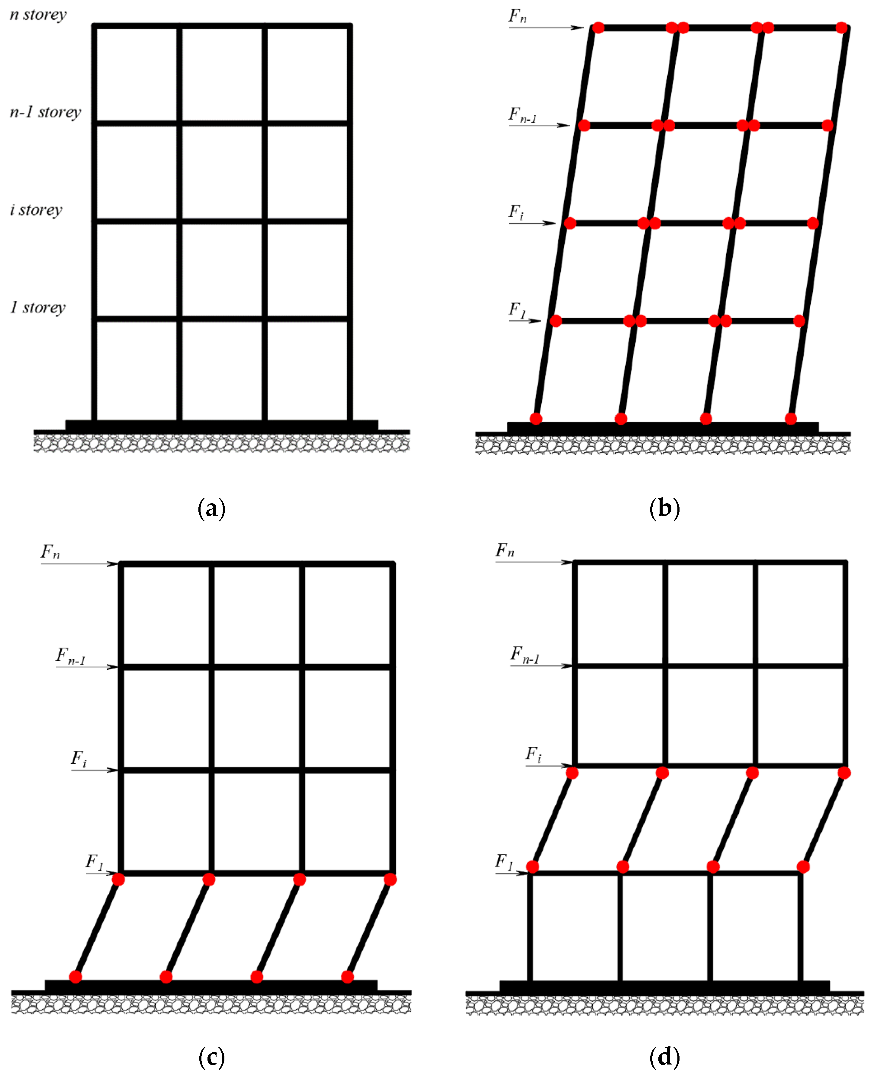
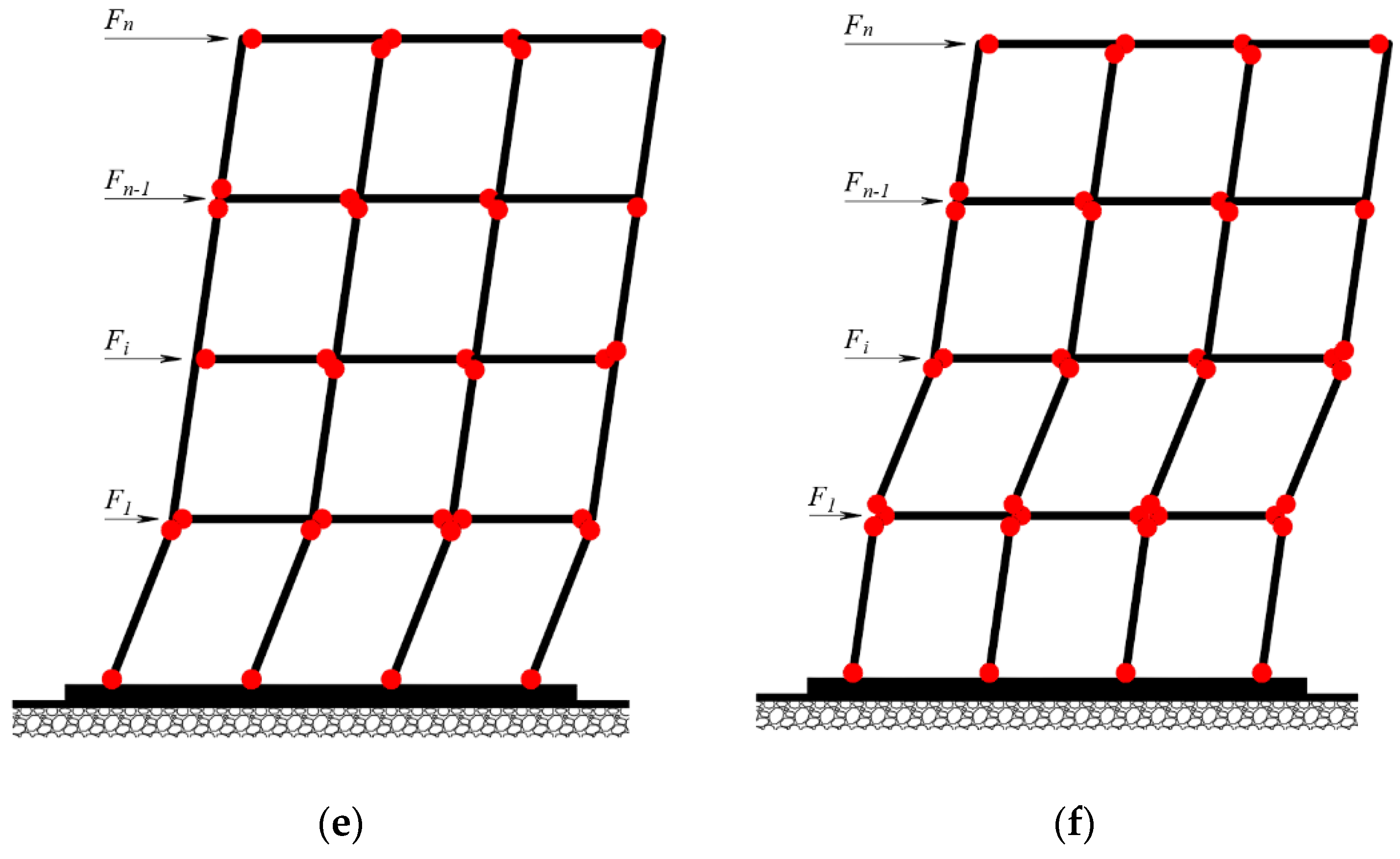
3. Seismic Response of the MR RC Frame Structures through Theoretical and Analytical Implications
- considering the rigid slab in the horizontal plane (for rigid-type floor) [27];
- there is a possibility that the RC beams have a superior bending stiffness compared to the RC columns [11];
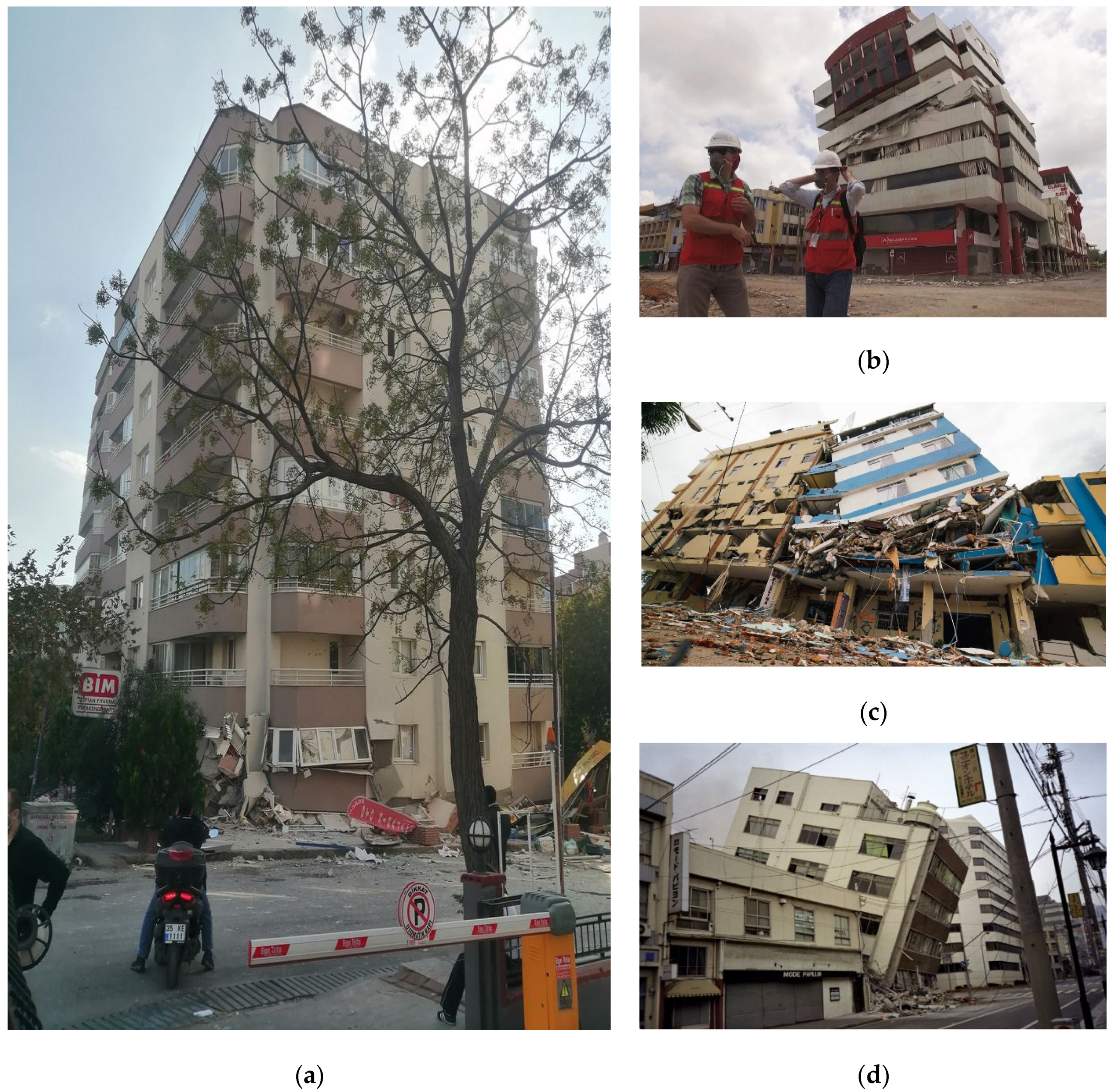
4. Real Seismic Response of MR RC Frame Structures and Experimental Research
- Extreme cracking of the RC beam-column joint;
- Deformation of marginal areas of RC columns;
- Slab cracking in the areas of interaction with the RC walls;
- Structural deformation of the ground floor walls and in other areas along the height of the structure, etc.
5. Conclusions That Specify and Reinforce the Need for the Current Analytical Study
6. Complex Static Non-Linear Analysis of the Representative Pure Moment Resisting (MR) Reinforced Concrete (RC) Frame Model
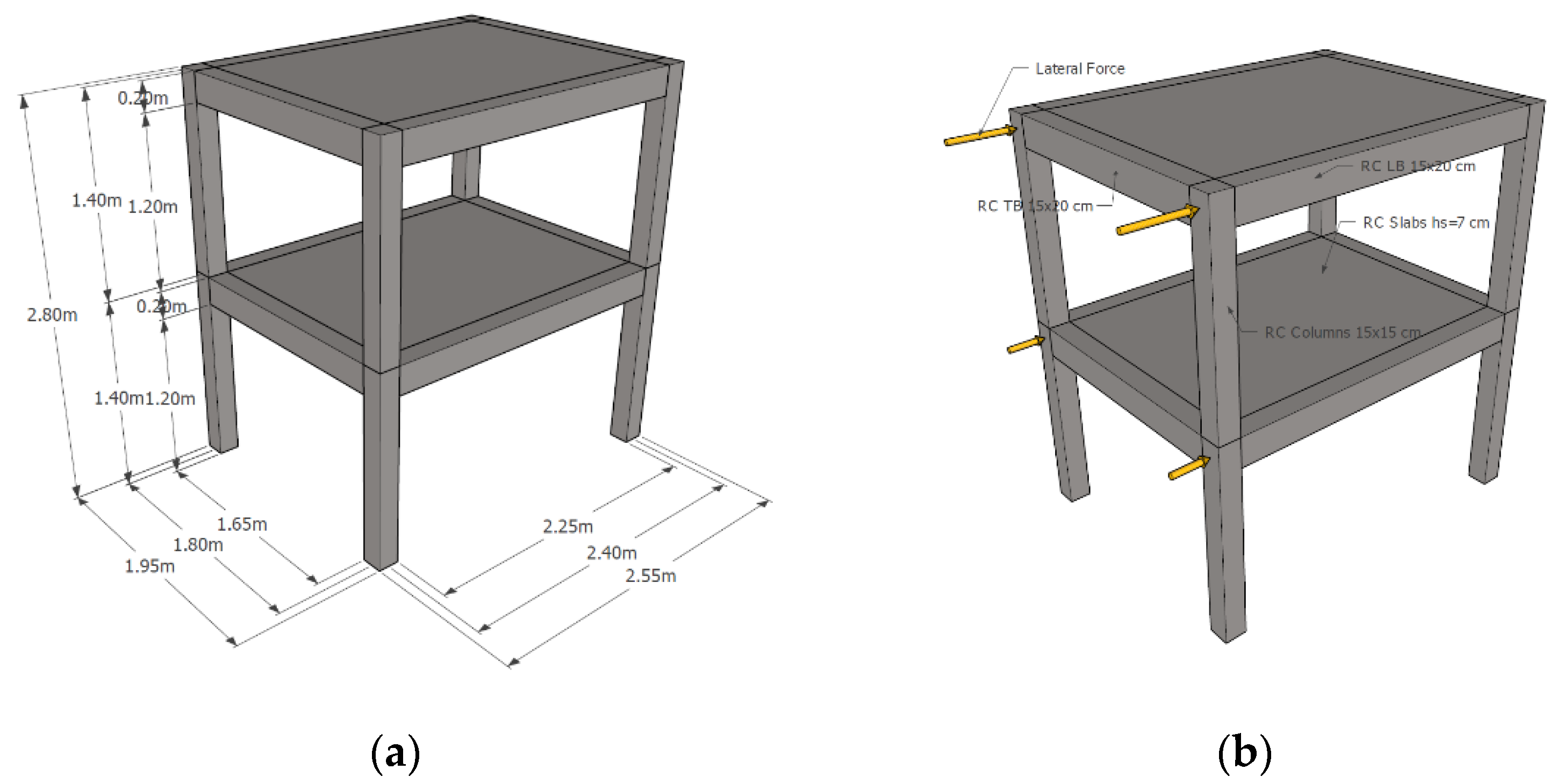
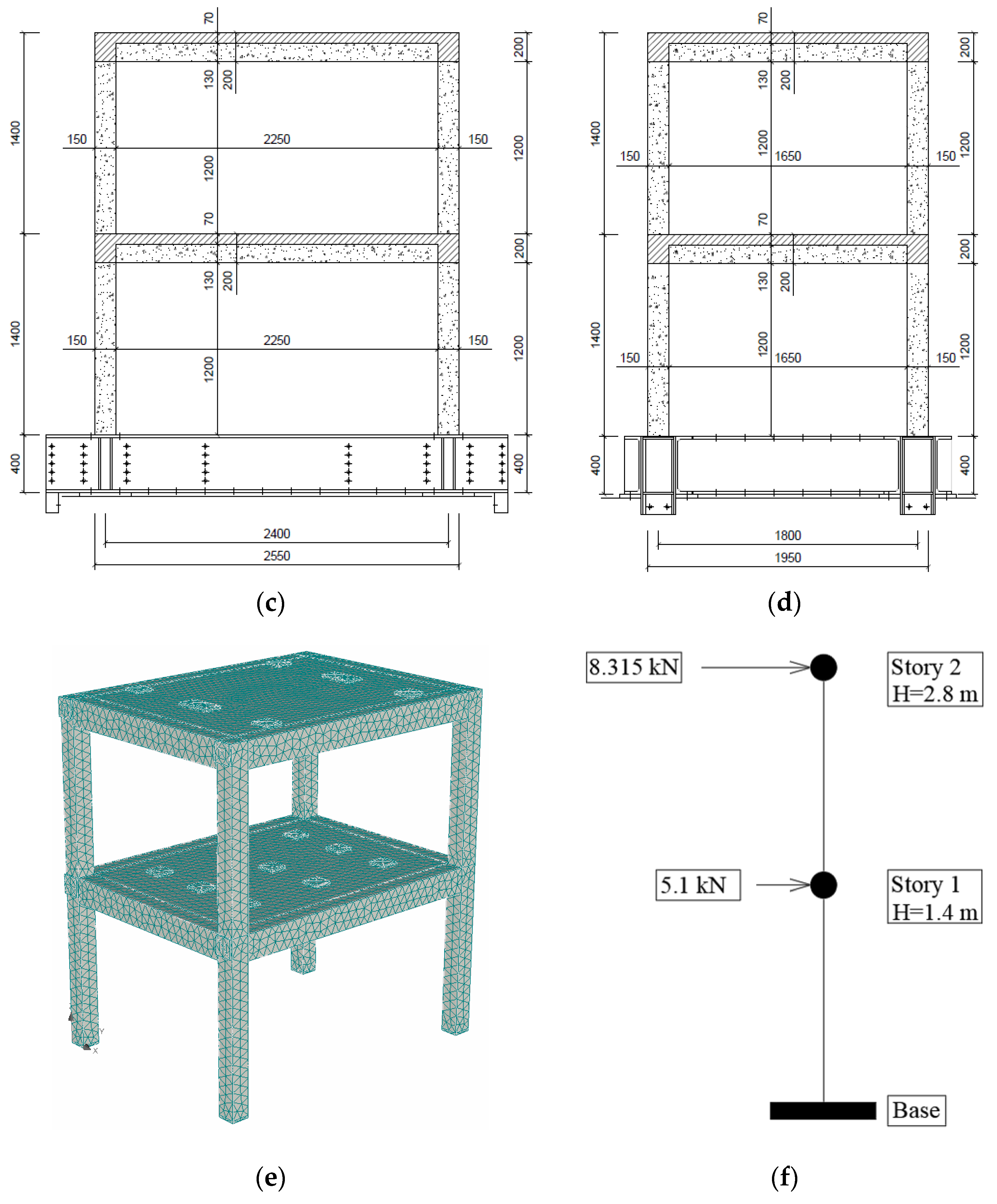
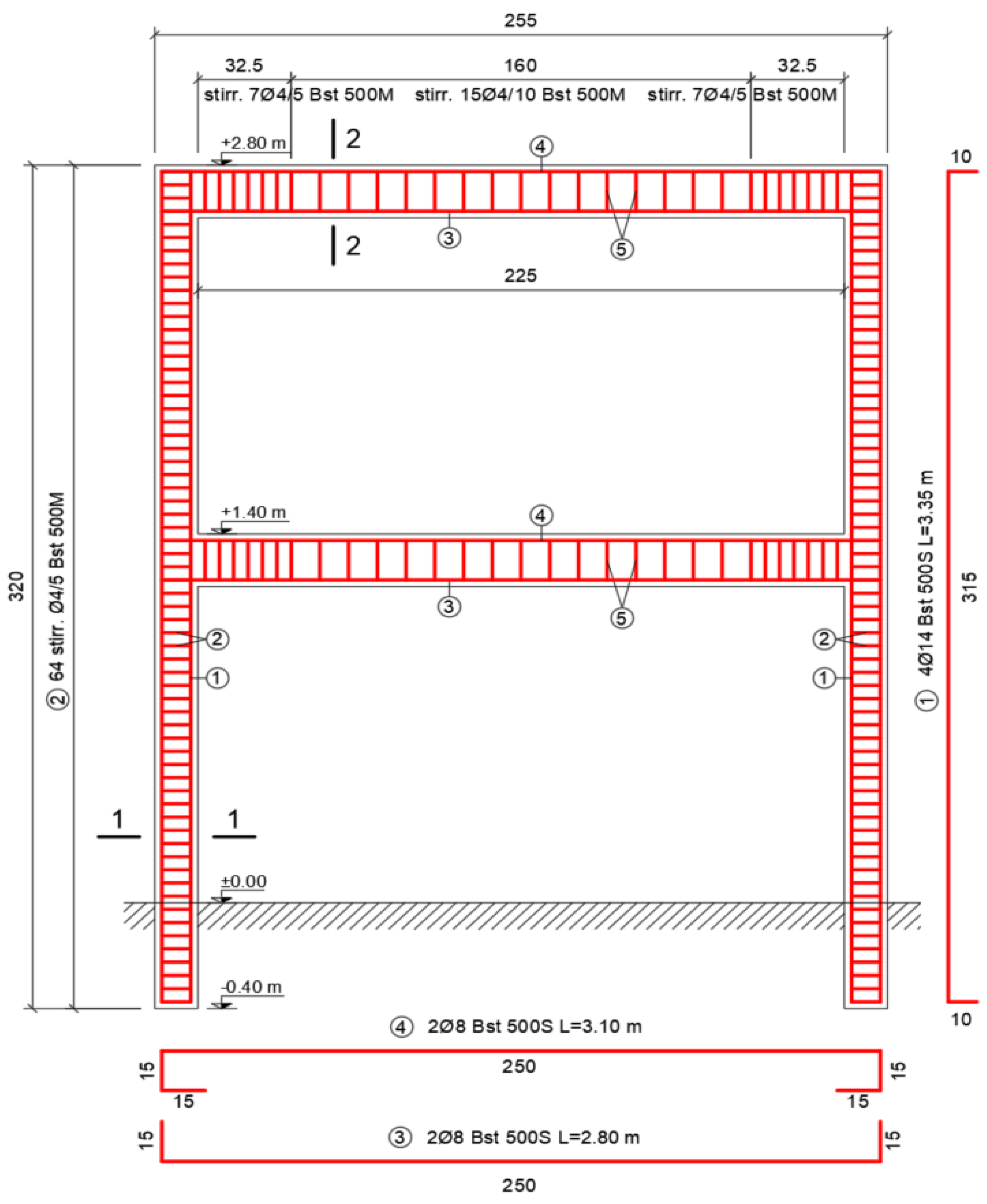
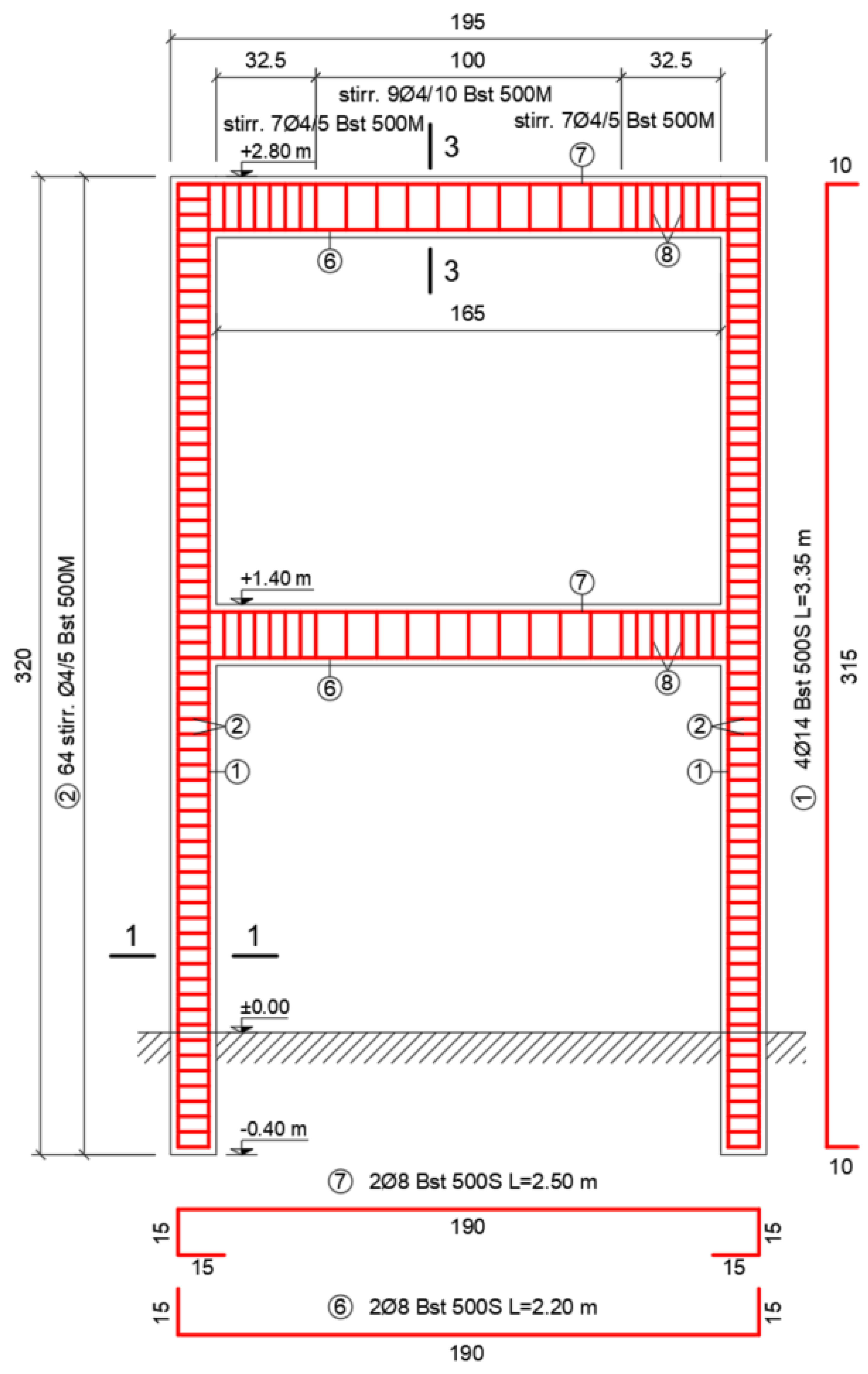
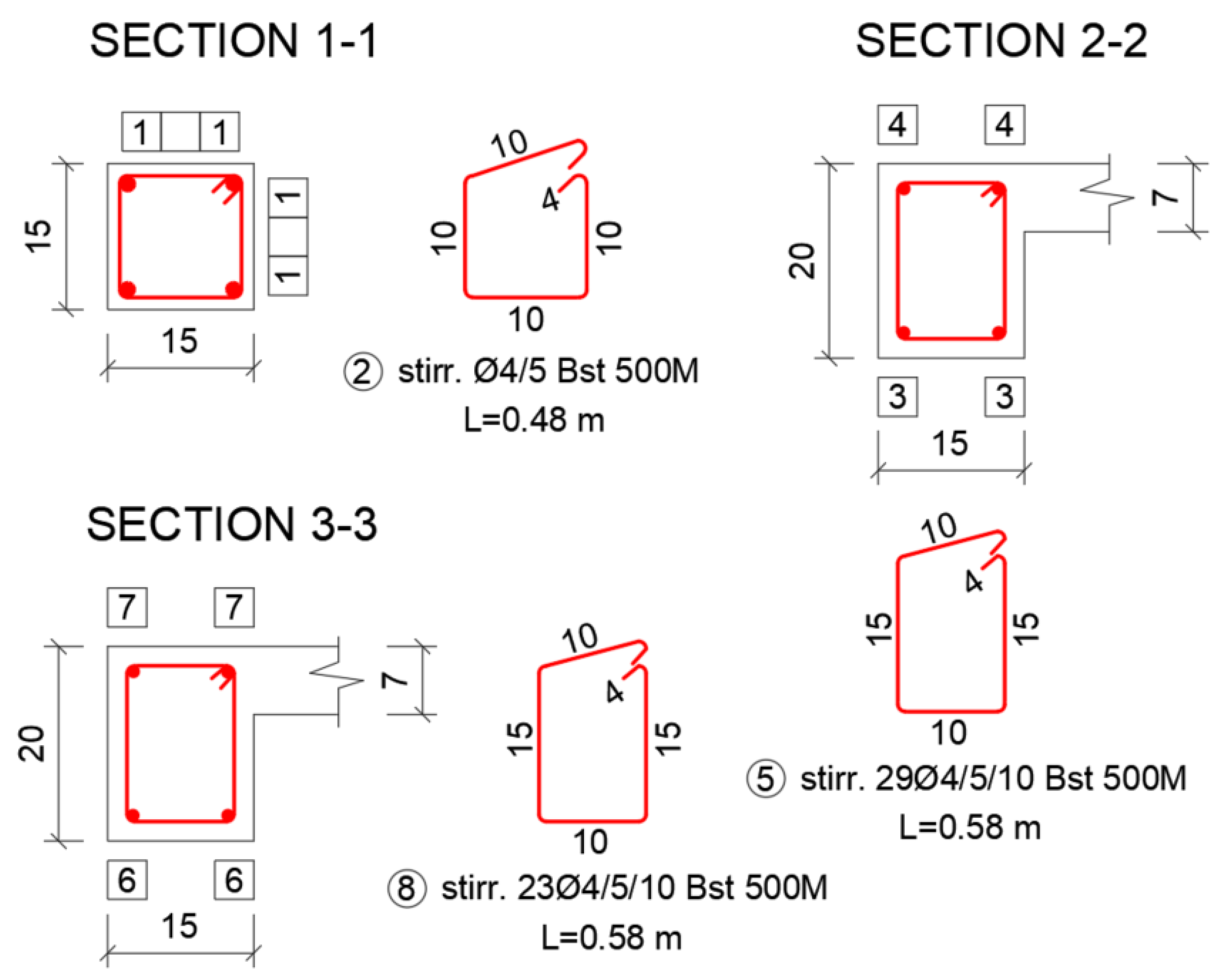
6.1. General Aspects
- Beams;
- Slabs;
- Columns.
6.2. Input Data Consideration
- The influence of the geometric shape of the drilled holes regarding the local deformation mode of the structural element;
- The influence of the variability of the dimensions of the drilled holes regarding the local deformation mode of the structural element;
- the constant/variable distance between the drilled holes with the specified implicit value and the effect of such distances upon the local deformation mode of the structural element;
- The constant/variable distance between the rows of drilled holes with the specified implicit value and the effect of these distances upon the local deformation mode of the structural element;
- The distance from the node/column with the specified implicit value;
- The influence of the positioning of the rows of drilled holes in a zig-zag/parallel pattern, etc., upon the local deformation mode of the structural element.
7. Analytical Results and Complementary Comments
7.1. Analytical Results
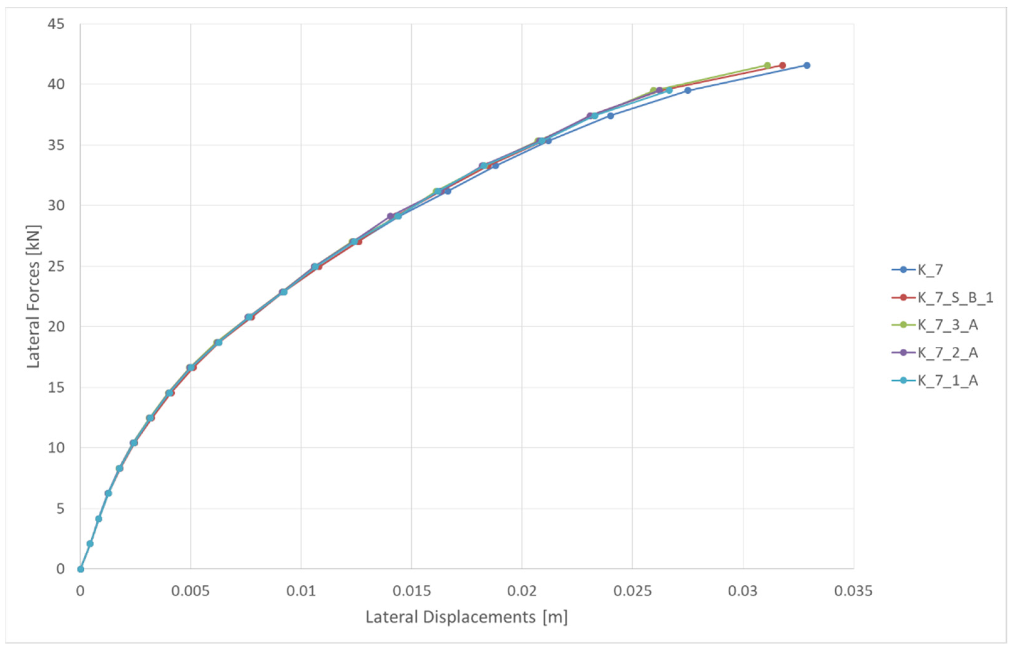
- Ultimate lateral force (Fu);
- Ultimate lateral displacement of the structural system (du);
- The lateral force corresponding to structural yielding of the equivalent SDOF structural system (F*y);
- The horizontal displacement at the top level of the structure corresponding to structural yielding of the equivalent SDOF structural system (d*y);
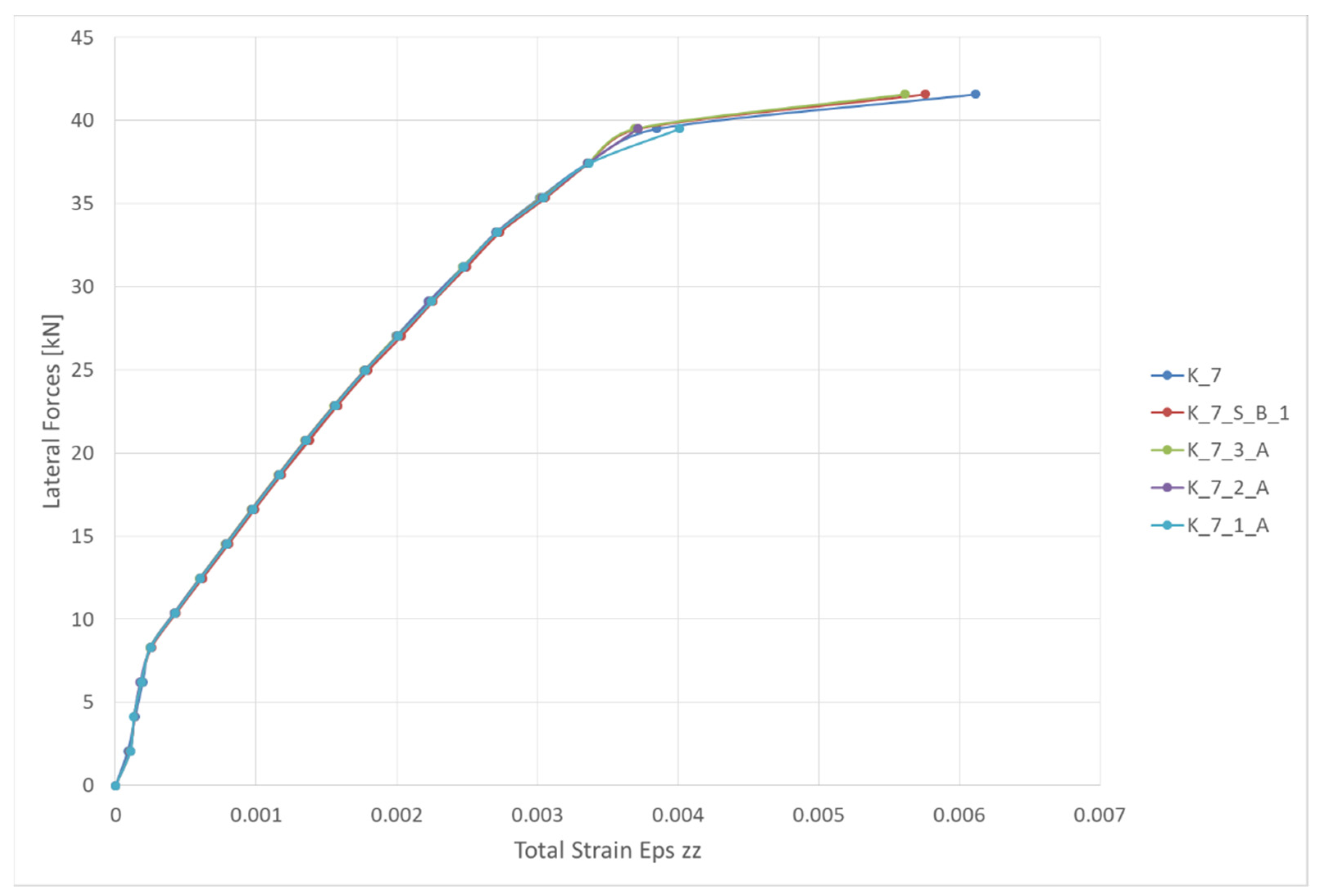
- The total specific deformations Eps zz;
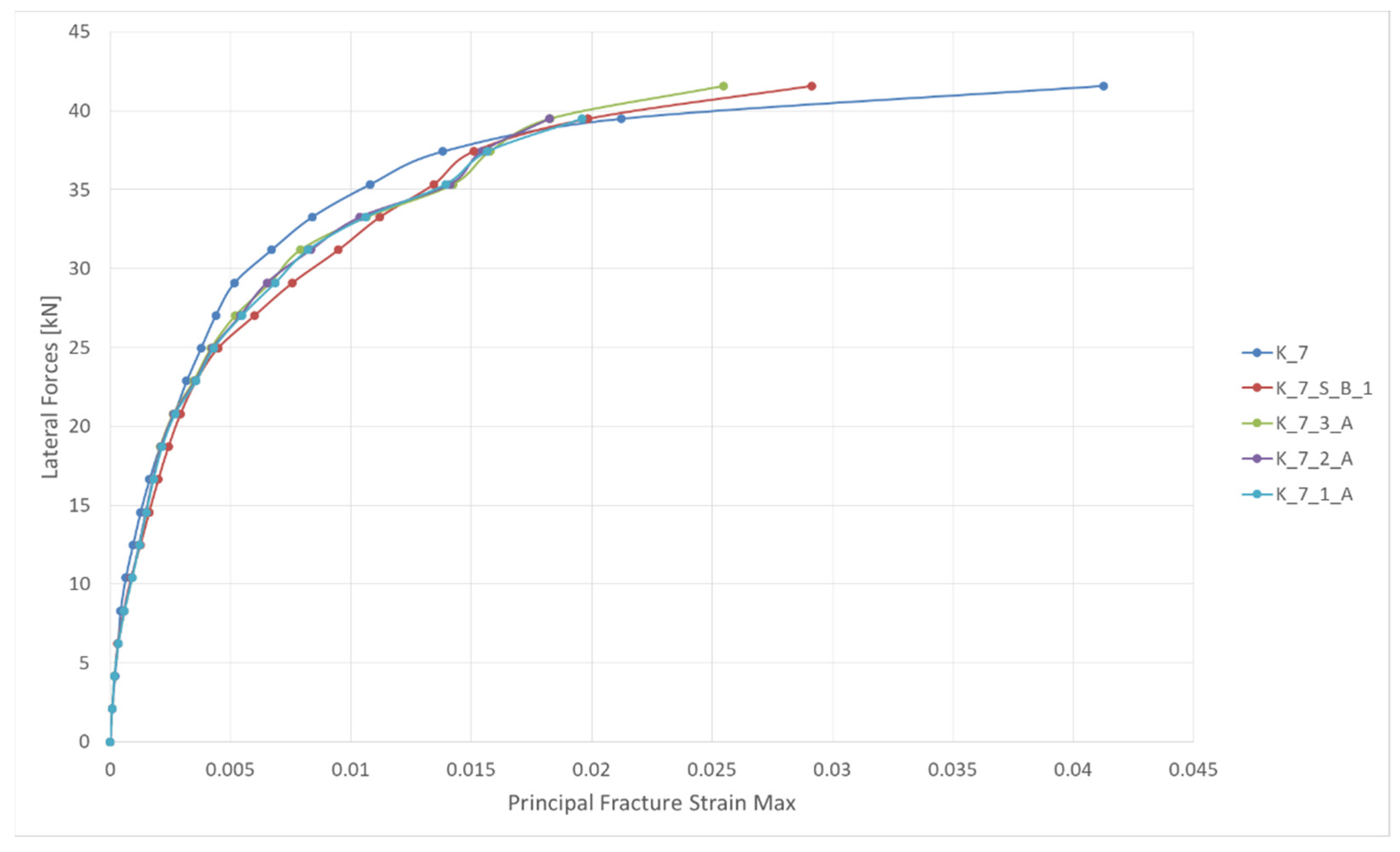
- The main (maximum) failure deformations;
- The cracking panel for the final step of lateral loading.
7.2. Complementary Comments
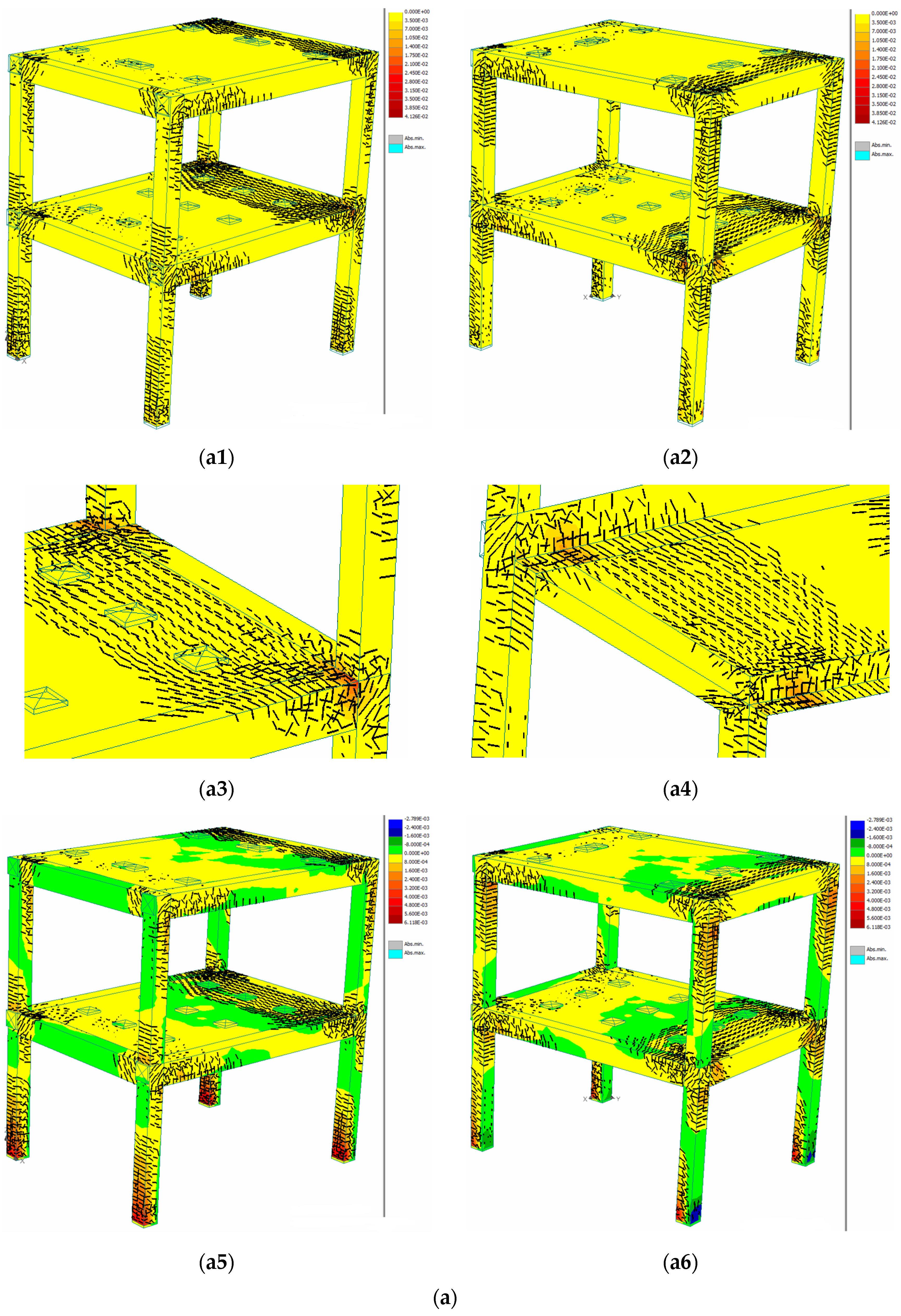
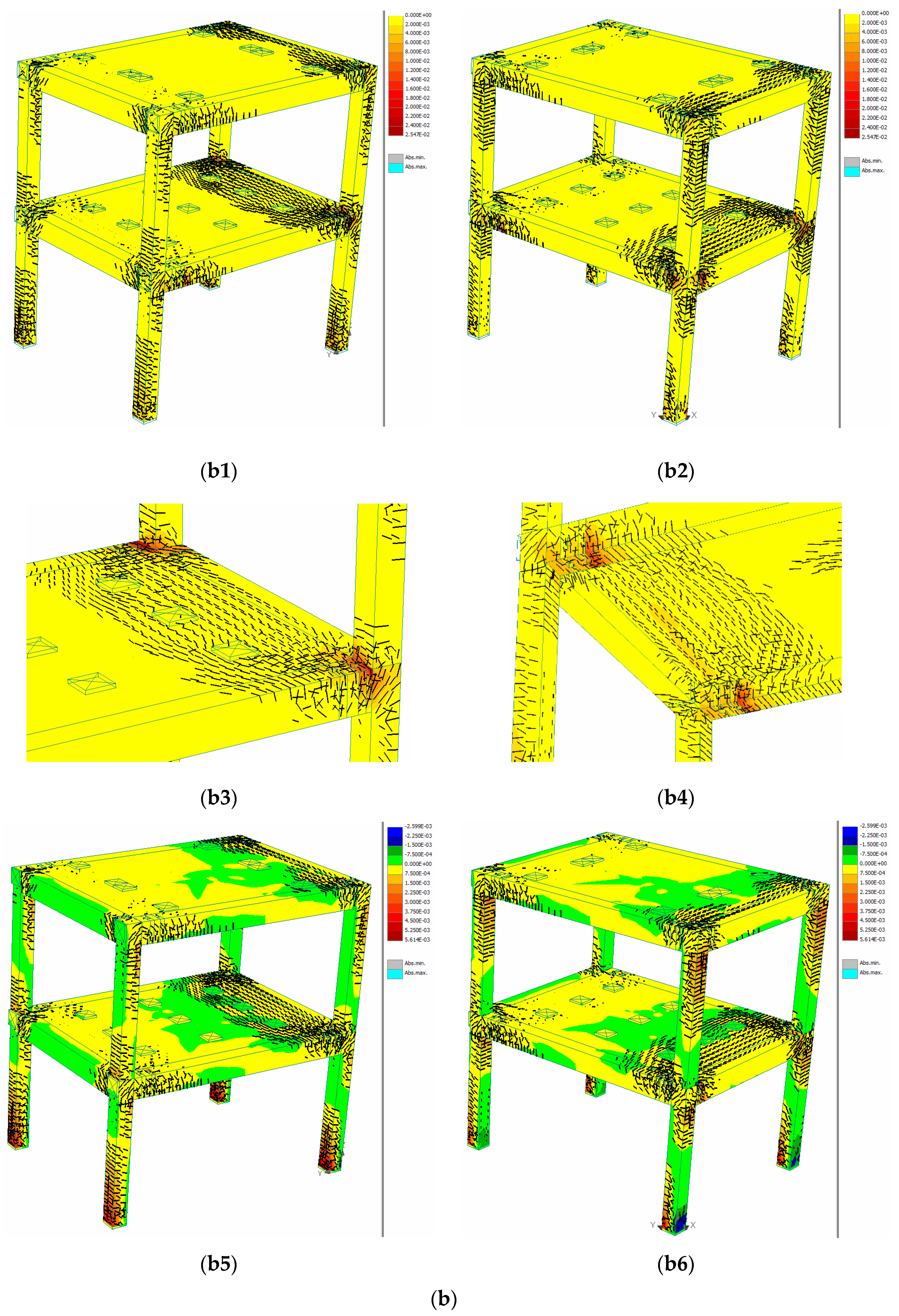
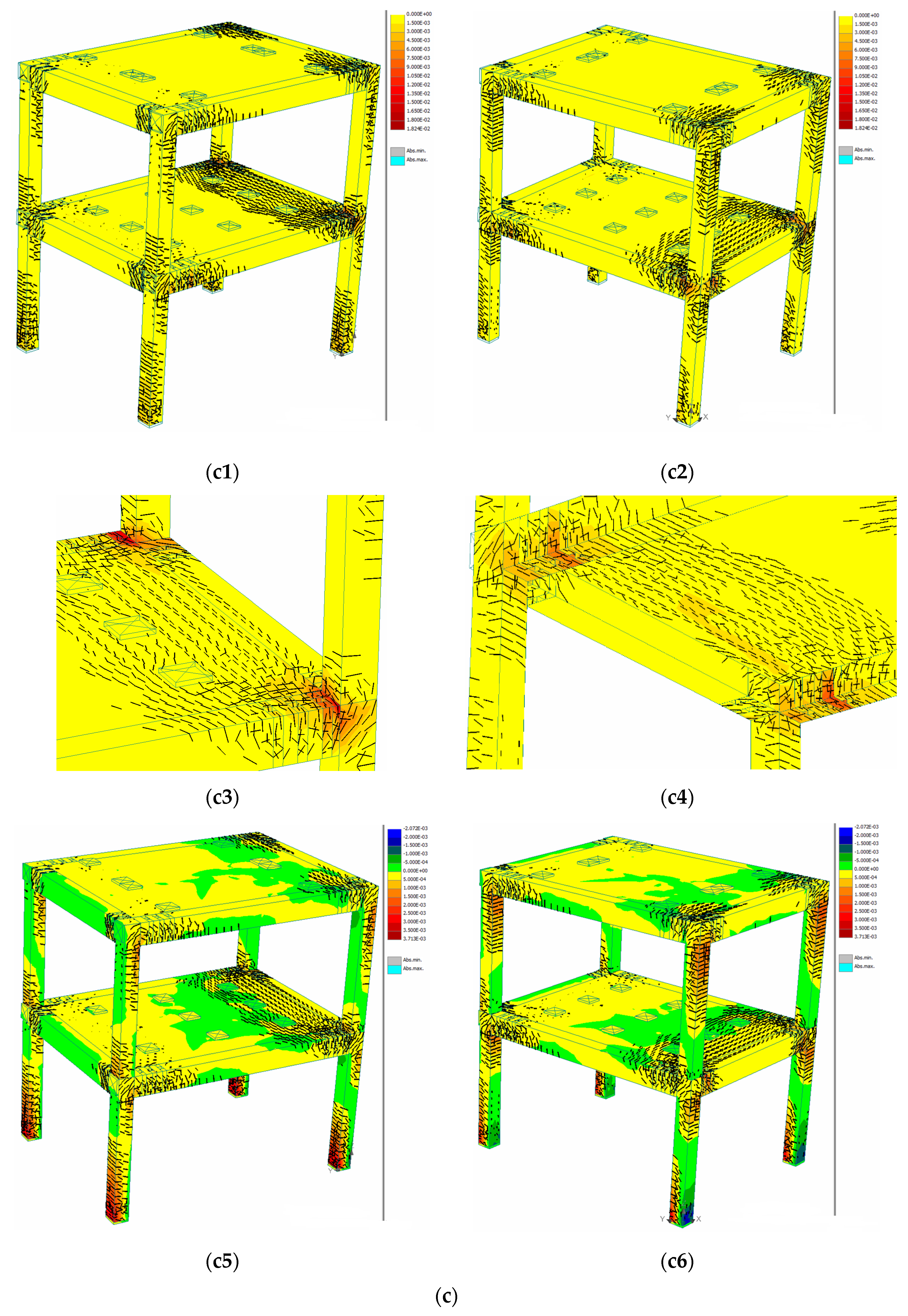
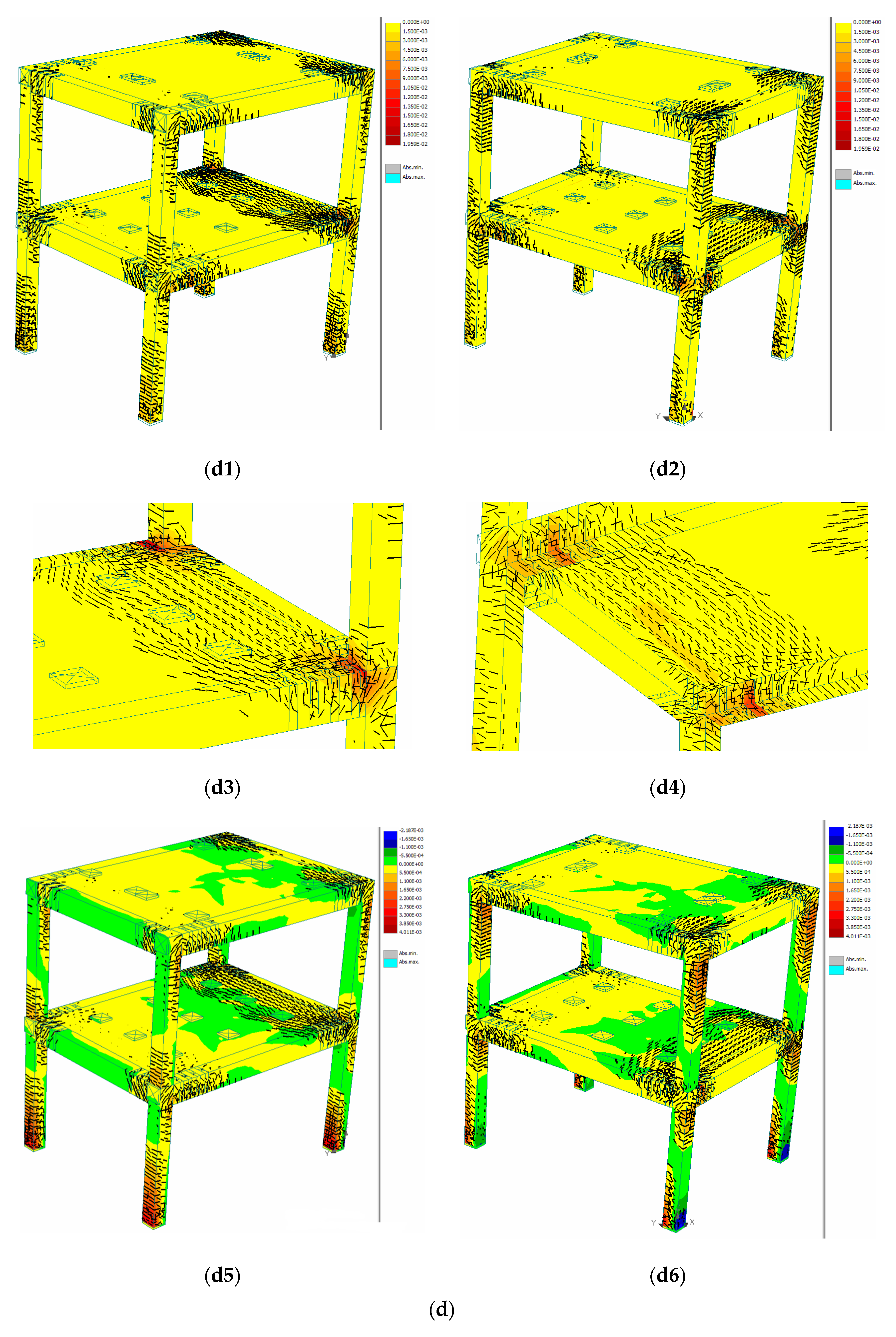
- The number of drilled holes in the longitudinal and transversal RC beams influences the state of cracking/deformation of the zone with a plastic deformation potential, for each step of lateral loading. Consequently, for the K_7_1_A structural model in which the beams have a maximum number of drilled holes, the zones with plastic potential crack much faster (they exhibit important cracks from a lower loading step) and influence the deformation state of the RC slab. As the number of drilled holes in the beams decreases (as is the case for K_7_2_A and K_7_3_A models), the maximum main failure deformations affect the beam-column frame node and the RC column ends with a greater intensity (see Figure 14b,c).
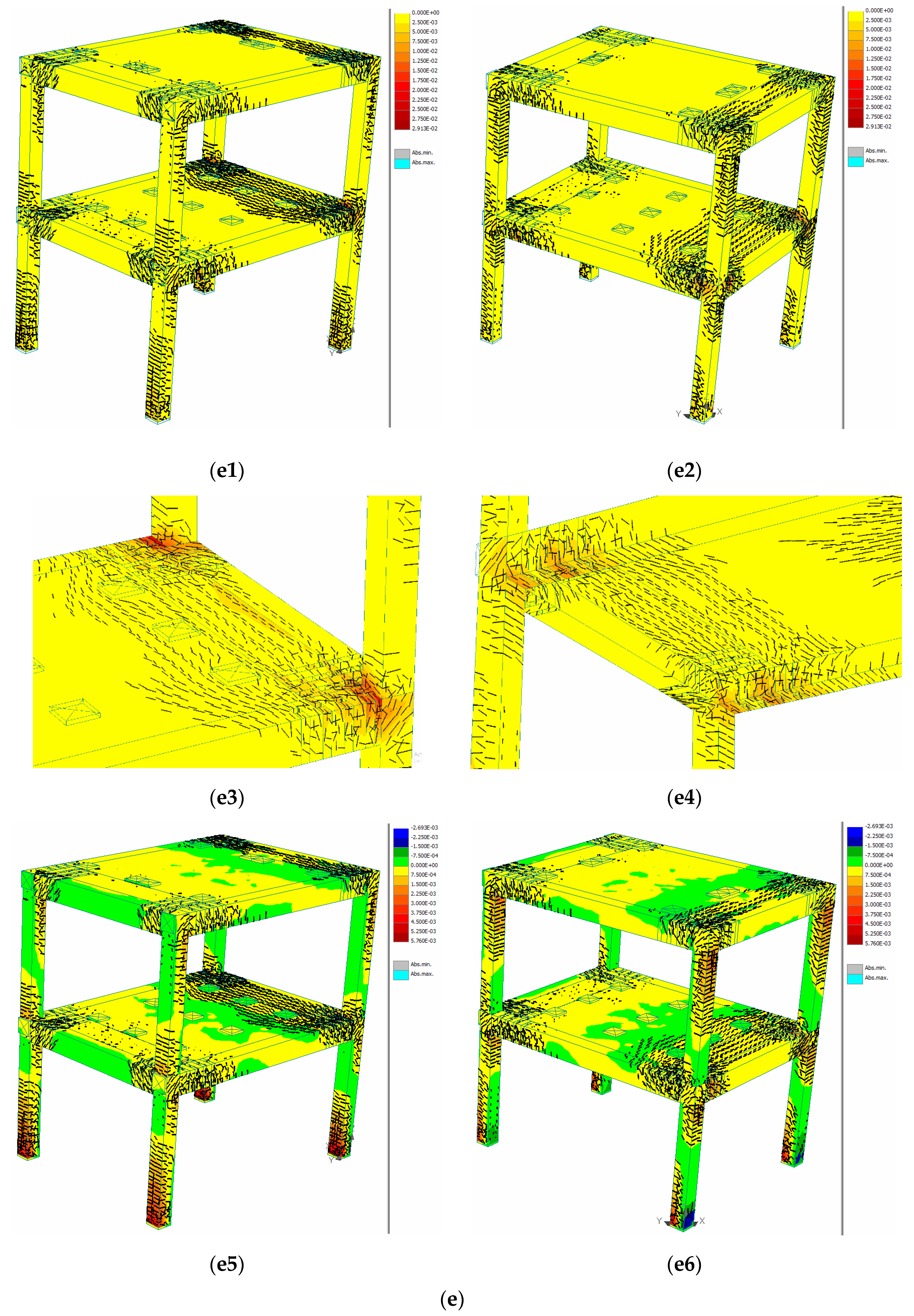
- The number of vertical drilled holes considered in the corner zones of the RC slabs for the K_7_S_B_1 analytical frame model influences not only the structural cracking and deformation state of the respective zone (immediately adjacent to the drilled holes) with a plastic deformation potential, but also the cracking mode of the adjacent zones (i.e., the beam end zones) (Figure 14e). Additionally, the potentially plastic zones with vertically drilled holes in the corners of the slabs have become “migration zones” for the cracks/deformations from the longitudinal beams towards the transversal beams and towards the slab. This mechanism occurs in a shorter time (for a smaller number of lateral loading steps of the analytical model) and far more efficiently in comparison with the situation of the K_7 model. A part of the negative effects pertaining to the beam-column frame node and to the marginal zones of the RC columns is thus mitigated.
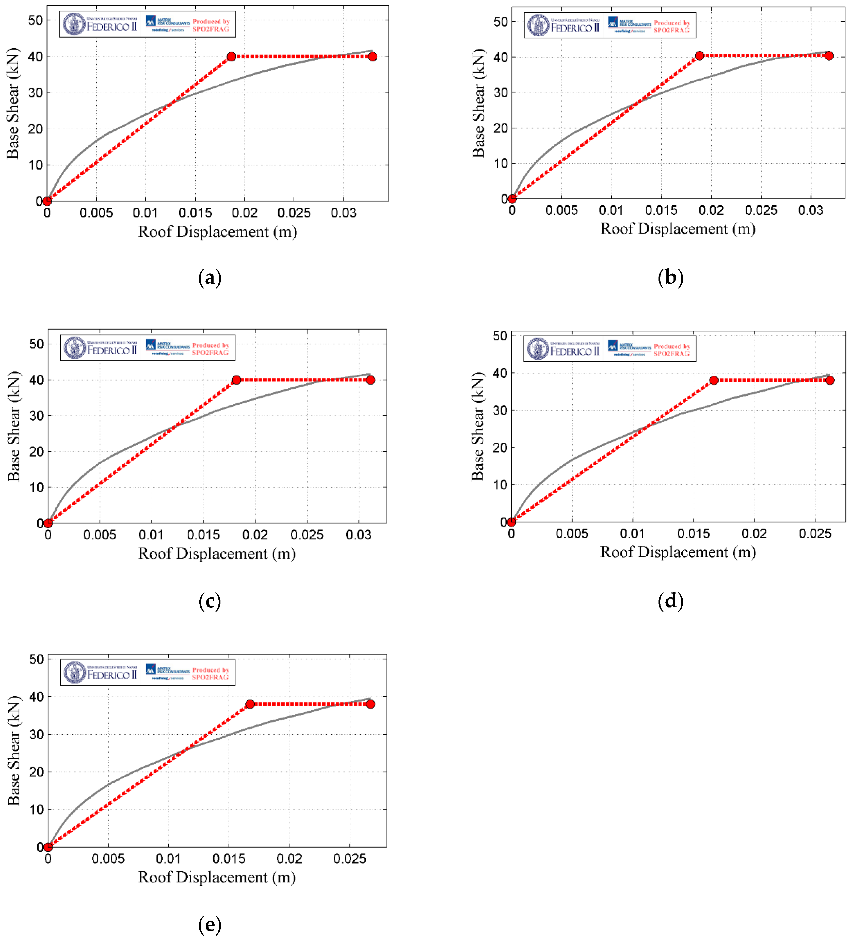
- The SPO curves presented in Figure 13 prove the incapacity for a complete visualisation of the global seismic response mode of the structures and can even lead to the obtainment of wrong conclusions. Thus, by analysing the bilinearised SPO curves from Figure 13, a conclusion that the unaffected model K_7 presents a global seismic response superior to the other analytical models may be reached.
8. Conclusions
- The guiding and concentration of the maximum failure deformations (PFSM) of concrete in the marginal (“weakened”) areas of the beams with a reduced section (through the employment of vertically drilled holes) was achieved;
- The migration of cracks from the longitudinal beams to the transversal ones along the path of the corner zones of the drilled slabs was observed; as such, a partial “conservation” of the structural integrity (of strength and stiffness) of the beam-column frame node was accomplished;
- The failure of concrete and the reinforcement yielding in RC beam areas with a reduced section was noted;
- The interruption of the mechanism of development for the common rigid block “beams-slab-frame nodes” was achieved;
- The reduction of the cracking length influence of the slabs upon the cracking length of the reinforced concrete beams was observed;
- The reduction of the local destruction (failure) mechanism (effect) of the beam-column frame node was observed;
- The reduction of the mechanism (effect) of the plastic deformation concentration in the superior and inferior zones of the reinforced concrete columns was noted;
- The occurrence of complex seismic energy dissipation mechanisms through the registering of plastic deformations in beams, slabs and partially in frame nodes and end zones of the reinforced concrete columns was detected.
- The integrity of the capacity and global design concept for the type of discussed structural system was achieved;
- The ductile mechanism “Strong Columns-Weak Beams” was partially achieved for the MR RC frame systems;
- The current design norms and regulations of seismic design for MR RC frame systems were respected;
- The base of this research included the real seismic response of reinforced concrete frame structures and the seismic response of the same type of structures discussed in other analytical studies.
Author Contributions
Funding
Institutional Review Board Statement
Informed Consent Statement
Data Availability Statement
Conflicts of Interest
References
- Cod de Proiectare Seismică”, Partea I, Prevederi de Proiectare Pentru Clădiri, Indicativ P100-1, Ministerul Dezvoltării Regionale și Administrației Publice, Mai 2013; UTCB: București, Romania, 2013. (In Romanian)
- Eurocod 8: Proiectarea Structurilor Pentru Rezistența la Cutremur, Partea 1: Reguli Generale, Acțiuni Seismice și Reguli Pentru Clădiri, Indicativ SR EN 1998-1; ASRO: București, Romania, 2004. (In Romanian)
- Paulay, T.; Priestley, M.J.N. Seismic Design of Reinforced Concrete and Masonry Buildings; John Wiley & Sons: New York, NY, USA, 1992. [Google Scholar]
- Budescu, M.; Ciongradi, I. Inginerie Seismică; Politehnium: Iași, Romania, 2014. (In Romanian) [Google Scholar]
- Postelnicu, T. Proiectarea Structurilor de Beton Armat în Zone Seismice; MarLink: București, Romania, 2012. (In Romanian) [Google Scholar]
- Stratan, A. Dinamica Structurilor și Inginerie Seismică; Note de curs: Timișoara, Romania, 2014. (In Romanian) [Google Scholar]
- Bai, J.; Ou, J. Plastic Limit-State Design of Frame Structures Based on the Strong-Column Weak-Beam Failure Mechanism. In Proceedings of the 15th World Conference on Earthquake Engineering, Lisboa, Portugal, 24–28 September 2012. [Google Scholar]
- Ishiyama, Y. Introduction to Earthquake Engineering and Seismic Codes in the World; Hokkaido University: Hokkaido, Japan, 2011. [Google Scholar]
- Akiyama, H. Collapse modes of structures under strong motions of earthquake. Ann. Geophys. 2002, 45, 791–798. [Google Scholar] [CrossRef]
- Sococol, I.; Olteanu-Donțov, I.; Mihai, P.; Iftode, V.-I. Seismic response of ½ scaled two storey reinforced concrete moment resisting frame system using nonlinear static analysis, Computational Civil Engineering (CCE 2021). IOP Conf. Ser. Mater. Sci. Eng. 2021, 1141, 012009. [Google Scholar] [CrossRef]
- Sococol, I.; Mihai, P.; Toma, I.-O.; Venghiac, V.-M.; Olteanu-Dontov, I. Influence of Concrete Strength Class on the Plastic Hinges Location for a Reinforced Concrete Moment-Resisting Frame Structure with Consideration of the Horizontal Stiffening Effect of the Slab. Bull. Polytech. Inst. Jassy Constr. Archit. Sect. 2020, 66, 95–108. [Google Scholar]
- Sococol, I.; Mihai, P.; Toma, I.-O.; Venghiac, V.-M.; Olteanu-Dontov, I. Static Non-linear Analysis of an RC Moment Resisting Frame by Considering Different Values for the Longitudinal Reinforcement Ratio in the Columns. Bull. Polytech. Inst. Jassy Constr. Archit. Sect. 2020, 66, 91–106. [Google Scholar]
- Sococol, I.; Mihai, P.; Toma, I.-O.; Olteanu-Dontov, I.; Venghiac, V.-M. The Influence of the RC Beams Cross Section on the Dissipative Seismic Response of a Moment Resisting RC Frame System. Bull. Polytech. Inst. Jassy Construction. Archit. Sect. 2020, 66, 21–38. [Google Scholar]
- Sococol, I.; Mihai, P.; Toma, I.-O.; Olteanu-Dontov, I.; Venghiac, V.-M. Stress-Strain Relation Laws for Concrete and Steel Reinforcement Used in Non-linear Static Analytical Studies of the Moment Resisting Reinforced Concrete (RC) Frame Models. Bull. Polytech. Inst. Jassy Constr. Archit. Sect. 2021, 67, 17–29. [Google Scholar] [CrossRef]
- Sococol, I.; Petrescu, T.C.; Mihai, P.; Babor, D.T. Influence of the longitudinal steel ration in RC beams and steel reinforcement ration in RC slabs on the seismic energy dissipation mechanisms for a MR RC frame structure, Civil Engineering Conference. IOP Conf. Ser. Mater. Sci. Eng. 2022; Unpublished results-pending publication. [Google Scholar]
- ATENA Software. Available online: http://www.cervenka.cz (accessed on 18 January 2021).
- El-Attar, A.G.; White, R.N.; Gergely, P. Shake Table Test of a 1/6 Scale Two-Story Lightly Reinforced Concrete Building; Cornell University: New York, NY, USA, 1991. [Google Scholar]
- Harris, H.G.; Sabnis, G.M. Structural Modeling and Experimental Techniques, Second Edition; CRC Press: Boca Raton, FL, USA, 1999. [Google Scholar]
- Moncarz, P.D.; Krawinkler, H. Theory and Application of Experimental Model Analysis in Earthquake Engineering; Stanford University: San Jose, CA, USA, 1981. [Google Scholar]
- Buildings Collapsed in IZMIR, Turkey after a Magnitude 6.9 Earthquake. Large Amount of Damage Reported throughout the City. 2020. Available online: https://turkey.liveuamap.com/en/2020/30-october-buildings-collapsed-in-izmir-turkey-after-a-magnitude (accessed on 26 April 2021).
- The Ecuador Exchange: A Step Toward Earthquake-Resistant Cities. 2016. Available online: https://www.architectmagazine.com/practice/the-ecuador-exchange-a-step-toward-earthquake-resistant-cities_o2 (accessed on 26 April 2021).
- Tzu Chi Begins Disaster Relief Assessment after Earthquake in Ecuador. 2016. Available online: https://tzuchi.us/blog/tzu-chi-begins-disaster-relief-assessment-after-earthquake-in-ecuador (accessed on 26 April 2021).
- Kobe Earthquake of 1995. Available online: https://www.britannica.com/event/Kobe-earthquake-of-1995 (accessed on 26 April 2021).
- Dalal, S.P.; Dalal, P. Strength, Deformation and Fragility assessment of Reinforced Concrete Moment Resisting frame designed by Force Based Design and the Performance Based Plastic Design method for Seismic loads. Structures 2021, 29, 1154–1164. [Google Scholar] [CrossRef]
- Celik, O.C.; Ellingwood, B.R. Seismic fragilities for non-ductile reinforced concrete frames–Role of aleatoric and epistemic uncertainties. Struct. Saf. 2010, 32, 1–12. [Google Scholar] [CrossRef]
- Arruda, M.R.T.; Castro, L.M.S. Non-linear dynamic analysis of reinforced concrete structures with hybrid mixed stress finite elements. Adv. Eng. Softw. 2021, 153, 102965. [Google Scholar] [CrossRef]
- Belmouden, Y.; Lestuzzi, P. An equivalent frame model for seismic analysis of masonry and reinforced concrete buildings. Constr. Build. Mater. 2009, 23, 40–53. [Google Scholar] [CrossRef]
- Brunesi, E.; Nascimbene, R.; Parisi, F.; Augenti, N. Progressive collapse fragility of reinforced concrete framed structures through incremental dynamic analysis. Eng. Struct. 2015, 104, 65–79. [Google Scholar] [CrossRef]
- Brunesi, E.; Parisi, F. Progressive collapse fragility models of European reinforced concrete framed buildings based on pushdown analysis. Eng. Struct. 2017, 152, 579–596. [Google Scholar] [CrossRef]
- Hu, B.; Lv, H.-L.; Kundu, T. Experimental study on seismic behavior of reinforced concrete frame in primary and middle schools with different strengthening methods. Constr. Build. Mater. 2019, 217, 473–486. [Google Scholar] [CrossRef]
- U.S. Department of Homeland Security. Assessing Seismic Performance of Buildings with Configuration Irregularities; FEMA P-2012; Federal Emergency Management Agency: Oakland, CA, USA, 2018. [Google Scholar]
- Sococol, I.; Toma, I.-O.; Mihai, P.; Țăranu, N.; Budescu, M. An Alternative Approach to Improve the Capacity Design Concept for Moment Resisting Reinforced Concrete (RC) Frame Systems. In Proceedings of the 1st Croatian Conference on Earthquake Engineering, Zagreb, Croatia, 22–24 March 2021; University of Zagreb Faculty of Civil Engineering: Zagreb, Croatia, 2021. [Google Scholar] [CrossRef]
- Yan, L.; Gong, J. Development of displacement profiles for direct displacement based seismic design of regular reinforced concrete frame structures. Eng. Struct. 2019, 190, 223–237. [Google Scholar] [CrossRef]
- Wang, H.; Su, Y.; Zeng, Q. Design Methods of Reinforce-concrete Frame Structure to Resist Progressive Collapse in Civil Engineering. In Proceedings of the 2011 International Conference on Risk and Engineering Management (REM), Toronto, ON, Canada, 28–30 October 2011; p. 7. [Google Scholar]
- The Japan Building Disaster Prevention Association. Standard for Seismic Evaluation of Existing Reinforced Concrete Buildings, Guidelines for Seismic Retrofit of Existing Reinforced Concrete Buildings, Technical Manual for Seismic Evaluation and Seismic Retrofit of Existing Reinforced Concrete Buildings, 1st ed.; BRI, English Version; JICA: Osaka, Japan, 2001. [Google Scholar]
- Lists of 21st-Century Earthquakes. 2021. Available online: https://en.wikipedia.org/wiki/Lists_of_21st-century_earthquakes (accessed on 26 April 2021).
- Japan, Researchers Test 10-Storey Concrete Building for Resilience Against ‘New Kobe Earthquake’. 2015. Available online: https://www.ibtimes.co.uk/japan-researchers-test-10-storey-concrete-building-resilience-against-new-kobe-earthquake-1532970 (accessed on 26 April 2021).
- Wang, D.; Li, H.-N.; Li, G. Experimental tests on reinforced concrete columns under multi-dimensional dynamic loadings. Constr. Build. Mater. 2013, 47, 1167–1181. [Google Scholar] [CrossRef]
- Taheri, A.; Tasnimi, A.A.; Moghadam, A.S. Experimental investigation on the seismic behavior and damage states of reinforced high strength concrete columns. Structures 2020, 27, 163–173. [Google Scholar] [CrossRef]
- Li, Y.; Yin, S.; Dai, J.; Liu, M. Numerical investigation on the influences of different factors on the seismic performance of TRC-strengthened RC columns. J. Build. Eng. 2020, 30, 101245. [Google Scholar] [CrossRef]
- Zembaty, Z.; Kowalski, M.; Pospisil, S. Dynamic identification of a reinforced concrete frame in progressive states of damage. Eng. Struct. 2006, 28, 668–681. [Google Scholar] [CrossRef]
- Kamath, P.; Sharma, U.K.; Kumar, V.; Bhargava, P.; Usmani, A.; Singh, B.; Singh, Y.; Torero, J.; Gillie, M.; Pankaj, P. Full-scale fire test on an earthquake-damaged reinforced concrete frame. Fire Saf. J. 2015, 73, 1–19. [Google Scholar] [CrossRef] [Green Version]
- Rizwan, M.; Ahmad, N.; Khan, A.N. Seismic performance assessment of reinforced concrete moment resisting frame with low strength concrete. Structures 2021, 30, 1140–1160. [Google Scholar] [CrossRef]
- Pohoryles, D.A.; Melo, J.; Rossetto, T.; Varum, H.; D’Ayala, D. Effect of slab and transverse beam on the FRP retrofit effectiveness for existing reinforced concrete structures under seismic loading. Eng. Struct. 2021, 234, 111991. [Google Scholar] [CrossRef]
- Li, S.; Zuo, Z.; Zhai, C.; Xu, S.; Xie, L. Shaking table test on the collapse process of a three-story reinforced concrete frame structure. Eng. Struct. 2016, 118, 156–166. [Google Scholar] [CrossRef]
- Hou, S.; Zhang, H.; Han, X.; Ou, J. Damage monitoring of the RC frame shaking table test and comparison with FEM results. Procedia Eng. 2017, 210, 393–400. [Google Scholar] [CrossRef]
- Zhang, H.; Li, H.-N.; Li, C.; Cao, G.-W. Experimental and numerical investigations on seismic responses of reinforced concrete structures considering strain rate effect. Constr. Build. Mater. 2018, 173, 672–686. [Google Scholar] [CrossRef]
- Liu, J.; Zhang, J.; Li, X.; Cao, W. Cyclic behavior of damage-controllable steel fiber reinforced high-strength concrete reduced-scale frame structures. Eng. Struct. 2021, 232, 111810. [Google Scholar] [CrossRef]
- Sococol, I.; Mihai, P.; Olteanu-Dontov, I. Ductility–Concept for Improving the Seismic Response for Structural Reinforced Concrete Frame Systems, Bulletin of the Polytechnic Institute of Jassy. Constr. Archit. Sect. 2019, 65, 17–30. [Google Scholar]
- Cervenka, V.; Jendele, L.; Cervenka, J. ATENA Program Documentation. Part 1. Theory; Cervenka Consulting Ltd.: Prague, Czech Republic, 2012. [Google Scholar]
- Sococol, I.; Mihai, P.; Iftode, V.I.; Olteanu-Dontov, I. Study Regarding the Stiffness Influence of Slab to Beams for a Plan Structural Reinforced Concrete Frame System in Seismic Zones. In Proceedings of the Computational Civil Engineering Conference, CCE, Iasi, Romania, 30–31 May 2019; Materials Science and Engineering. IOP Publishing: Bristowl, UK, 2019; Volume 586. [Google Scholar] [CrossRef] [Green Version]
- Bitencourt, L.A.G., Jr.; Manzoli, O.L.; Trindade, Y.T.; Rodrigues, E.A.; Dias-da-Costa, D. Modeling reinforced concrete structures using coupling finite elements for discrete representation of reinforcements. Finite Elem. Anal. Des. 2018, 149, 32–44. [Google Scholar] [CrossRef] [Green Version]
- Sousa, J.B.M., Jr.; Muniz, C.F.D.G. Analytical integration of cross section properties for numerical analysis of reinforced concrete, steel and composite frames. Eng. Struct. 2007, 29, 618–625. [Google Scholar] [CrossRef]
- Kupfer, H.; Hilsdorf, H.K.; Rusch, H. Behavior of Concrete under Biaxial Stress. J. ACI 1969, 66, 656–666. [Google Scholar]
- Shiming, S.; Yupu, S. Dynamic biaxial tensile-compressive strength and failure criterion of plain concrete. Constr. Build. Mater. 2013, 40, 322–329. [Google Scholar] [CrossRef]
- Ivashenko, Y.; Ferder, A. Experimental studies on the impacts of strain and loading modes on the formation of concrete “stress-strain” relations. Constr. Build. Mater. 2019, 209, 234–239. [Google Scholar] [CrossRef]
- Bi, J.; Huo, L.; Zhao, Y.; Qiao, H. Modified the smeared crack constitutive model of fiber reinforced concrete under uniaxial loading. Constr. Build. Mater. 2020, 250, 118916. [Google Scholar] [CrossRef]
- Wei, H.; Wu, T.; Liu, X.; Zhang, R. Investigation of stress-strain relationship for confined lightweight aggregate concrete. Constr. Build. Mater. 2020, 256, 119432. [Google Scholar] [CrossRef]
- Dong, S.; Wang, Y.; Ashour, A.; Han, B.; Ou, J. Uniaxial compressive fatigue behavior of ultra-high performance concrete reinforced with super-fine stainless wires. Int. J. Fatigue 2021, 142, 105959. [Google Scholar] [CrossRef]
- Xu, T.; Castel, A.; Gilbert, R.I.; Murray, A. Modeling the tensile steel reinforcement strain in RC-beams subjected to cycles of loading and unloading. Eng. Struct. 2016, 126, 92–105. [Google Scholar] [CrossRef]
- Wang, Z.-H.; Li, L.; Zhang, Y.-X.; Zheng, S.-S. Reinforcement model considering slip effect. Eng. Struct. 2019, 198, 109493. [Google Scholar] [CrossRef]
- Long, X.; Wang, C.-Y.; Zhao, P.-Z.; Kang, S.-B. Bond strength of steel reinforcement under different loading rates. Constr. Build. Mater. 2020, 238, 117749. [Google Scholar] [CrossRef]
- Sabău, M. Simulated data on bond of steel reinforcement in self-compacting concrete. Data Brief 2020, 30, 105594. [Google Scholar] [CrossRef]
- CEB-FIP Model Code 1990; First Draft; Committee Euro-International du Beton: Lausanne, Switzerland, 1990; Available online: http://www.tocasa.es/zona2/CEB_FIP_model_code_1990_ing.pdf (accessed on 26 April 2021).
- Eurocod 2: Proiectarea Structurilor de Beton, Partea 1-1: Reguli Generale și Reguli Pentru Clădiri, INDICATIV SR EN 1992-1-1; ASRO: București, Romania, 2006. (In Romanian)
- Tehnică, U.; Asachi, G.; Iași, D. Grindă și placă pentru disipare de energie seismică. Patent Application A/00045, 12 February 2021. (In Romanian). [Google Scholar]
- Baltzopoulos, G.; Baraschino, R.; Iervolino, I.; Vamvatsikos, D. SPO2FRAG: Software for seismic fragility assessment based on static pushover. Bull. Earthq. Eng. 2017, 15, 4399–4425. [Google Scholar] [CrossRef]
- Baltzopoulos, G.; Baraschino, R.; Iervolino, I.; Vamvatsikos, D. SPO2FRAG [Computer Software]. AXA-DiSt; Universita Degli Studi di Napoli Federico II: Naples, Italy, 2017. [Google Scholar]
- Li, H.; Yi, T.; Gu, M.; Huo, L. Evaluation of earthquake-induced structural damages by wavelet transform. Prog. Nat. Sci. 2009, 19, 461–470. [Google Scholar] [CrossRef]
- Lin, S.-W.; Yi, T.-H.; Li, H.-N.; Ren, L. Damage Detection in the Cable Structures of a Bridge Using the Virtual Distortion Method. J. Bridge Eng. 2017, 22, 04017039. [Google Scholar] [CrossRef]


| NSC | CSC | LSRT | TSRT | LSR RC C [CS:15 × 15 cm] | LSR RC LB [CS:15 × 20 cm] | LSR RC TB [CS:15 × 20 cm] | TSR RC C | TSR RC LB and TB | R RC S [hs = 7 cm] | GR |
|---|---|---|---|---|---|---|---|---|---|---|
| K_7 | C20/25 | Bst 500S | Bst 500M | 4ϕ14 | 4ϕ8 | 4ϕ8 | 1ϕ4/1 CS | 1ϕ4/1 CS | ϕ6 | Figure 8(a2) |
| K_7_3_A | C20/25 | Bst 500S | Bst 500M | 4ϕ14 | 4ϕ8 | 4ϕ8 | 1ϕ4/1 CS | 1ϕ4/1 CS | ϕ6 | Figure 8(b2) |
| K_7_2_A | C20/25 | Bst 500S | Bst 500M | 4ϕ14 | 4ϕ8 | 4ϕ8 | 1ϕ4/1 CS | 1ϕ4/1 CS | ϕ6 | Figure 8(c2) |
| K_7_1_A | C20/25 | Bst 500S | Bst 500M | 4ϕ14 | 4ϕ8 | 4ϕ8 | 1ϕ4/1 CS | 1ϕ4/1 CS | ϕ6 | Figure 8(d2) |
| K_7_S_B_1 | C20/25 | Bst 500S | Bst 500M | 4ϕ14 | 4ϕ8 | 4ϕ8 | 1ϕ4/1 CS | 1ϕ4/1 CS | ϕ6 | Figure 8(e2) |
| NSC | RC Drilled Element Type in the Potentially Plastic Zone | Hole Type Depends on the Geometric Shape (Form) | Variable (V)/Constant (C) Size Holes | Number of Holes | Number of Rows of Holes | Constant (C)/Variable (V) Distance between Holes | Constant (C)/Variable (V) Distance between Rows of Holes | Minimum (Min)/Maximum (Max) Distance between Holes and RC B-C Joint/RC Column | Rows of Vertical Holes Positioning (Zig-Zag, Parallel etc.) | GR |
|---|---|---|---|---|---|---|---|---|---|---|
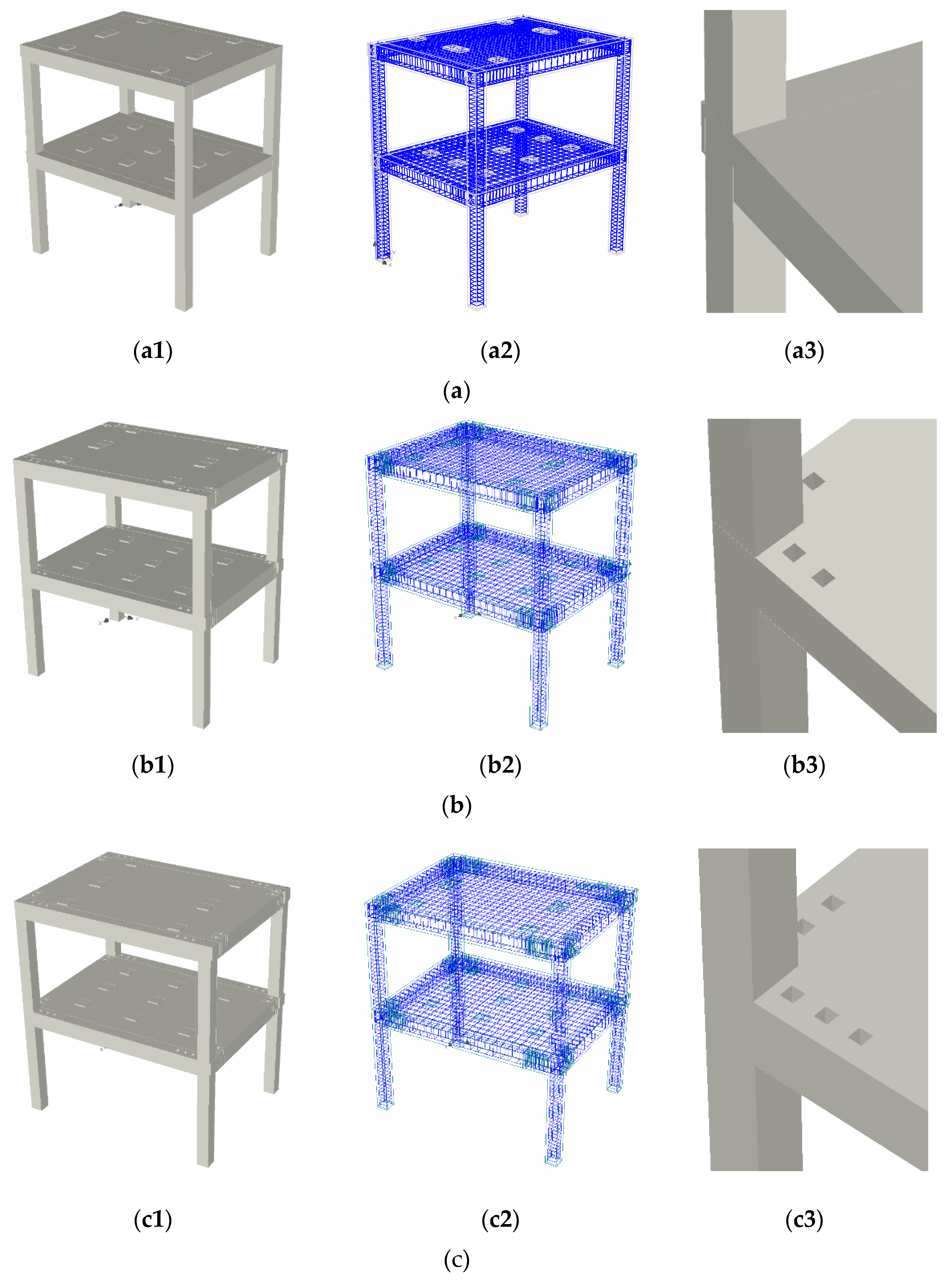
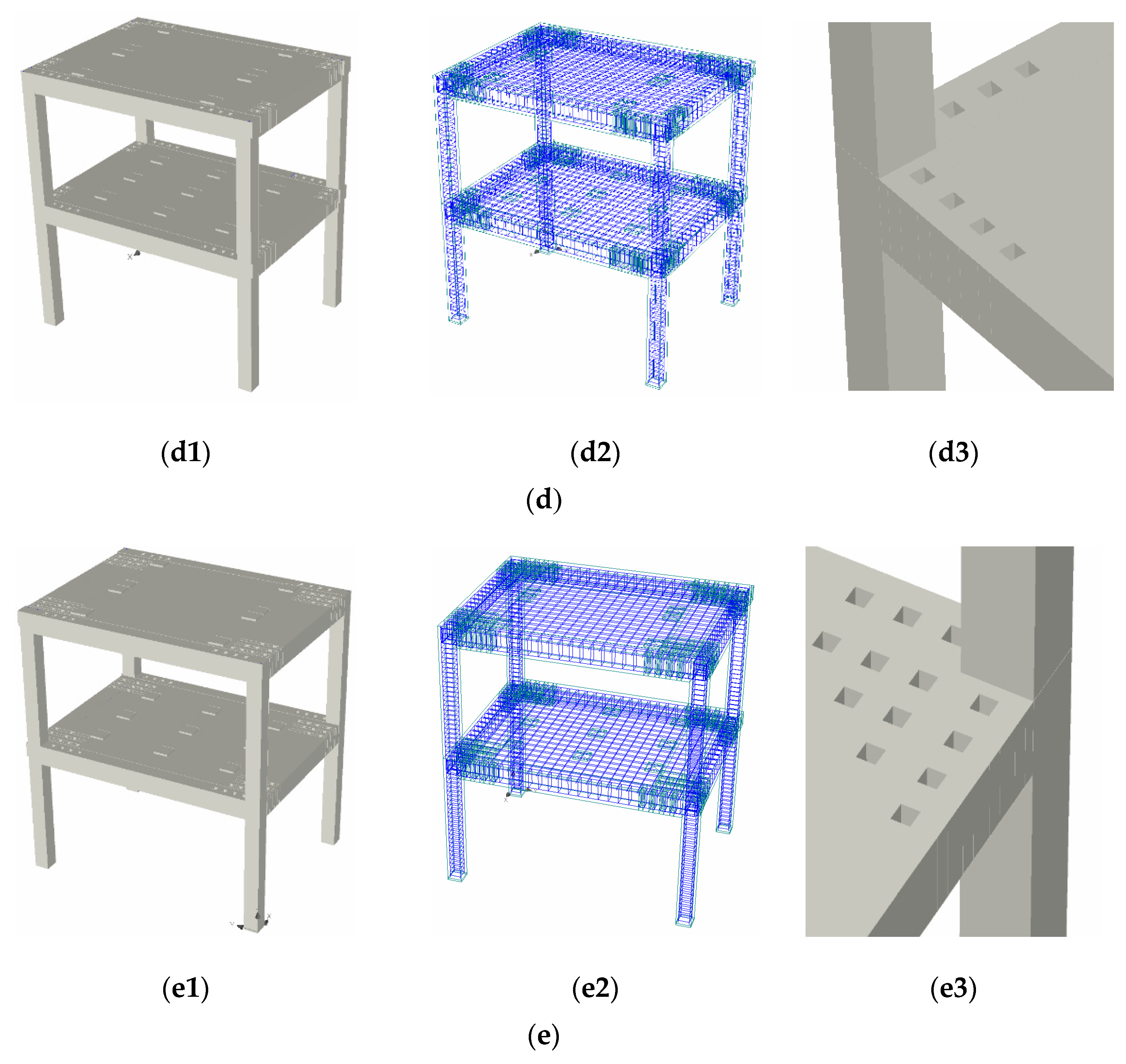
| K_7 | - | - | - | - | - | - | - | - | - | Figure 8(a1,a3) |
| K_7_3_A | beam | square holes | C | 2 for LB 1 for TB | 1 for LB 1 for TB | C | - | Min. | - | Figure 8(b1,b3) |
| K_7_2_A | beam | square holes | C | 3 for LB 2 for TB | 1 for LB 1 for TB | C | - | Min. | - | Figure 8(c1,c3) |
| K_7_1_A | beam | square holes | C | 4 for LB 3 for TB | 1 for LB 1 for TB | C | - | Min. | - | Figure 8(d1,d3) |
| K_7_S_B_1 | beam and slab | square holes | C | 4 for LB 3 for TB 6 for RC slab | 1 for LB 1 for TB 2 for RC slab | C | - - C | Min. | - - parallel | Figure 8(e1,e3) |
| NSC | Fu (kN) | du (m) | F*y (kN) | d*y (m) | SPO CB | TSE (CF) | TSE (TF) | GR TSE (CF/TF) | PFSM | GR PFSM |
|---|---|---|---|---|---|---|---|---|---|---|
| K_7 | 41.575 | 0.03288 | 40 | 0.0187 | Figure 13a | 0.002789 | 0.006118 | Figure 14(a3,a4) | 0.0413 | Figure 14(a1,a2) |
| K_7_3_A | 41.575 | 0.03109 | 40 | 0.0182 | Figure 13c | 0.002599 | 0.005614 | Figure 14(b5,b6) | 0.02547 | Figure 14(b1–b4) |
| K_7_2_A | 39.49625 | 0.0262 | 38.1 | 0.0167 | Figure 13d | 0.002072 | 0.003713 | Figure 14(c5,c6) | 0.01824 | Figure 14(c1–c4) |
| K_7_1_A | 39.49625 | 0.02665 | 38.1 | 0.0167 | Figure 13e | 0.002187 | 0.004011 | Figure 14(d5,d6) | 0.01959 | Figure 14(d1–d4) |
| K_7_S_B_1 | 41.575 | 0.03179 | 40.4 | 0.0188 | Figure 13b | 0.002693 | 0.00576 | Figure 14(e5,e6) | 0.02913 | Figure 14(e1–e4) |
| NSC | RC Beams Cracking Process | RC Columns Cracking Process | RC Slabs Cracking Process | RC Column-Beam Joint Cracking | Final Rupture—RC Structural Element/Elements | Zone/Zones of Final Rupture | RC Beam Cracking Length Limiting by RC Slab Cracking Area | Risk of the Common Rigid Block RC “Beam-Slab-Frame Node” Formation | Concrete Cracks Migration Process from the Longitudinal Beams to the Transverse Beams in the Adjacent Area of the Frame Node | GR | |||
|---|---|---|---|---|---|---|---|---|---|---|---|---|---|
| Local—in Potential Plastic Zones | On Entire Length | Local—in Marginal Areas | On Entire Height | Local Area | Extended Area | ||||||||
| K_7 | low | - | intense | low | low | medium to intense | intense | columns and nodes | marginal zones of the columns; entire volume of the nodes | yes | high with practical formation | low to insignificant | Figure 14a |
| K_7_3_A | medium | - | medium | low | low to medium | medium to intense | medium to intense | beams and nodes | marginal zones of the beams in reduced cross sections and immediately adjacent area of the beam-column joints | yes | medium with partial formation | low to medium | Figure 14b |
| K_7_2_A | medium to intense | - | medium | low | low to medium | medium to intense | medium to intense | beams and nodes | marginal zones of the beams in reduced cross sections and immediately adjacent area of the beam-column joints | yes | medium with partial formation | low to medium | Figure 14c |
| K_7_1_A | medium to intense | - | medium | low | medium | medium to intense | medium to intense | beams and nodes | marginal zones of the beams in reduced cross sections and immediately adjacent area of the beam-column joints | yes | medium with partial formation | low to medium | Figure 14d |
| K_7_S_B_1 | medium to intense | - | medium | low | medium to intense | medium to intense | medium | beams, slabs and nodes | marginal zones of the beams in reduced cross sections; corner area for reduced cross section of the slabs; partial volume of the beam-column joints | partial with limited influence | medium with low process formation | medium to high | Figure 14e |
Publisher’s Note: MDPI stays neutral with regard to jurisdictional claims in published maps and institutional affiliations. |
© 2022 by the authors. Licensee MDPI, Basel, Switzerland. This article is an open access article distributed under the terms and conditions of the Creative Commons Attribution (CC BY) license (https://creativecommons.org/licenses/by/4.0/).
Share and Cite
Sococol, I.; Mihai, P.; Petrescu, T.-C.; Nedeff, F.; Nedeff, V.; Agop, M. Analytical Study Regarding the Seismic Response of a Moment-Resisting (MR) Reinforced Concrete (RC) Frame System with Reduced Cross Sections of the RC Beams. Buildings 2022, 12, 983. https://doi.org/10.3390/buildings12070983
Sococol I, Mihai P, Petrescu T-C, Nedeff F, Nedeff V, Agop M. Analytical Study Regarding the Seismic Response of a Moment-Resisting (MR) Reinforced Concrete (RC) Frame System with Reduced Cross Sections of the RC Beams. Buildings. 2022; 12(7):983. https://doi.org/10.3390/buildings12070983
Chicago/Turabian StyleSococol, Ion, Petru Mihai, Tudor-Cristian Petrescu, Florin Nedeff, Valentin Nedeff, and Maricel Agop. 2022. "Analytical Study Regarding the Seismic Response of a Moment-Resisting (MR) Reinforced Concrete (RC) Frame System with Reduced Cross Sections of the RC Beams" Buildings 12, no. 7: 983. https://doi.org/10.3390/buildings12070983