Article

On-Site Risk Assessment Methodology of Historic Timber Structures: The Case Study of Santa Cruz Church

by
Javier Sola-Caraballo
,
José María Rincón-Calderón
,
Carlos Rivera-Gómez
*,
José Antonio López-Martínez
and
Carmen Galán-Marín
Departamento de Construcciones Arquitectónicas I, Escuela Técnica Superior de Arquitectura, Universidad de Sevilla, Avda. Reina Mercedes, 2, 41012 Seville, Spain
*
Author to whom correspondence should be addressed.
Buildings 2022, 12(7), 935; https://doi.org/10.3390/buildings12070935
Submission received: 6 May 2022 / Revised: 28 June 2022 / Accepted: 28 June 2022 / Published: 1 July 2022

Abstract

:
The conservation and repair of historic structures require significant resources. Therefore, it is important to conduct a complete assessment of the object. Specifically, historical timber frame structures are very common in the Spanish and Andalusian geographic area. This research proposes and develops a simplified approach to facilitate decision making when faced with this complex work. By the application of long-established non-destructive tests, such as organoleptic and measuring inspection, resistography, and electric moisture content test, combined with visual classification parameters, these data were used as boundary conditions into a simplified structural calculation method. This process, which is simpler than other calculation systems, allows compiling important information about the safety level of the structure and its critical points. Finally, it allows for a better approach to repair work while rationalizing resources. This method was applied to a historical structure, during an 18th century church repair project. The assessment methodology provided important information about the conservation state of the timber frame and its structural suitability.

1. Introduction

Historically, wood has been widely used for the construction of buildings, both in its envelope and in the structural system. As a material, it has characteristics that make it suitable for structural use: good density-strength ratio, lightness, existence of large parts, need for little manufacturing processes, ease of handling, and possibility of very quick prefabrication [1]. These were properties that heavy stone materials did not have. In addition, as a raw material, other qualities were added, such as the large number of resources offered by forests, ease of access, and their proximity to the urban centres. In the case of regions without tree masses, there was the possibility of transporting the material in a relatively simple way along river routes. For these reasons, timber structures have been one of the most widely used resources for the construction of light horizontal structures such as roofs and slabs.
One of the main challenges facing architecture today is the conservation and repair of the architectural heritage. With actual regulations on heritage preservation [2], the way in which buildings of historical value are conserved is defined, while public administrations are involved in the conservation task. These laws came to regulate what has already begun to be named “good architectural and patrimonial practices” in the different Restoration Letters (Athens 1931 [3], Venice 1964 [4]), or the subsequent letters of ICOMOS [5], where the structures are involved as an inherent element of the patrimonial property itself [6].
Therefore, these timber structures are widespread in Spain and particularly common in the Andalusian region, as part of the built heritage that must be considered when dealing with conservation and rehabilitation. These structures are also generally located in the roof system conformation, sometimes being subjected to severe weather conditions.
The best way for architecture to face these complex interventions is to investigate the subject to expand the base of specialized knowledge to apply in professional practice [7]. These investigations have been confronted from different points of view, always in order to expand knowledge about wood as a material and the construction systems used historically. In this field, the behaviour of structural timber has also been studied and in terms of how it is affected by the passage of time and degrading agents; in addition, once the problems are detected, we will know how to face the possible necessary repair interventions.

1.1. Aims and Objectives

The main objective of this research is to provide a simple procedure to deal with the numerous refurbishment processes needed for the vast built heritage with timber structures. Some researchers have addressed these issues before, and some guidelines have been proposed [8,9]. However, these works use either an advanced system of analysis or are in some way specific for the treated case study. In contrast, the proposed simplified methodology is intended to have a broad spectrum of application in timber structures.
Consequently, the novelty of this publication lies in the development of a new simplified approach to assess the structural behaviour of historical timber roof frames. Non-destructive tests combined with visual classification parameters are used to perform a simplified structural calculation method. Additionally, it allows the determination of the structure’s safety levels after having suffered years of use and possible deterioration. This process was tested during the course of some repair work on a late 18th century church roof. Taking advantage of this renovation and following the implementation of a new evaluation procedure, important information was obtained about this historic building.
This paper is part of a research with the overall aim of supporting decision making to deal with repair works on historical timber frame structures by proposing a systematic approach for adequate risk assessment for these constructive materials and solutions from the design-build perspective.
The present research proposes a synthetic method and basic guidelines to assess the structural behaviour of a timber structure through the implementation of Non-Destructive Tests (NDT) and a subsequent verification by means of a computational system of matrix linear calculation. To perform this, the process was implemented in a specific case study, the Santa Cruz Parish Church, the main church of Ecija, Spain. This church has some traditional carpentry structures resolved with a rafter-collar beam system. Due to the development of repair works, it has been possible to access, measure and study the structural elements. In addition, the repair works have addressed in independent structural modules, but with similar characteristics, which has allowed us to check and compare the state of the studied structure (unaltered) with others being intervened, where testing, substitutions, and extractions of the original material were carried out.
These comparisons between different states of similar timber structures have enabled the testing and confirmation of validity and, therefore, also the usefulness of the new assessment procedure proposed in the paper.

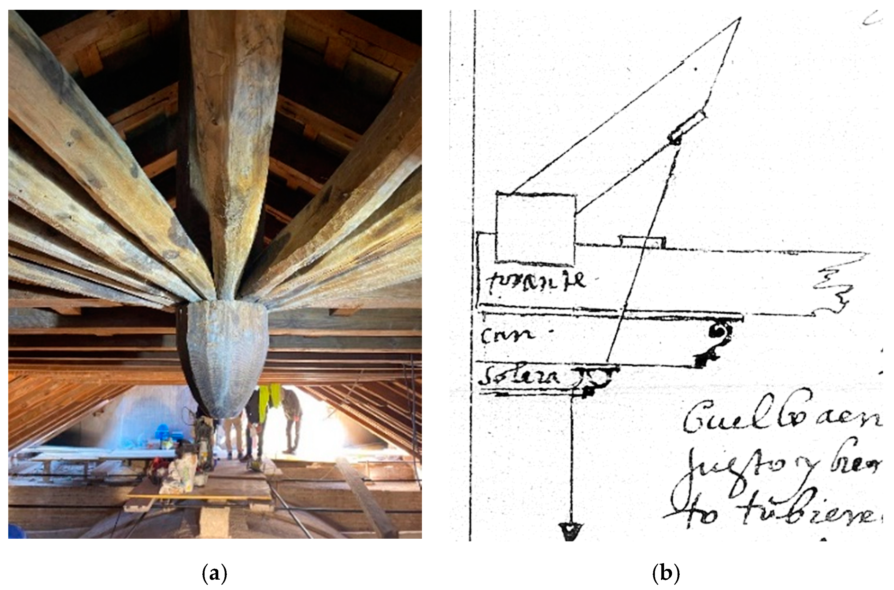
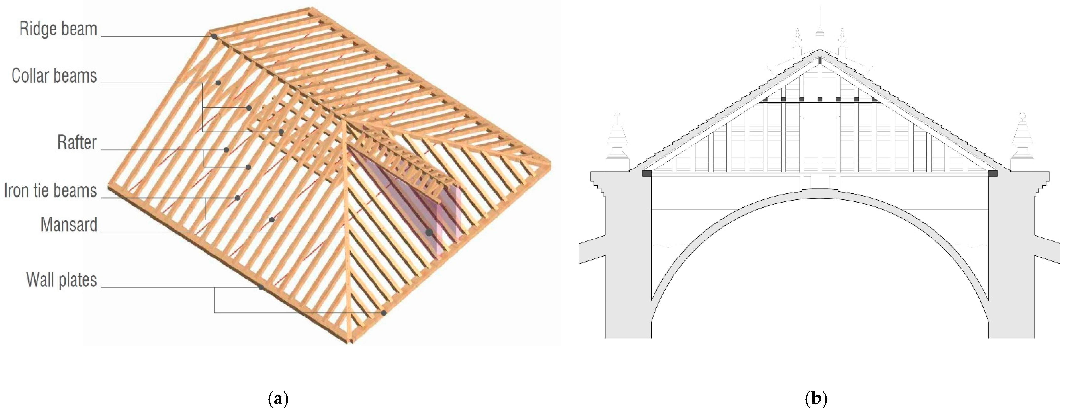
1.2. Background: Traditional Carpentry and Non-Destructive Testing Methods

Timber structures are widely widespread throughout the world with specific characteristics that vary locally [10]. Its lightness and versatility made it a perfect construction material that is mostly used in walls, structural floors, and roofs [11]. Historical and structurally, laced timber or timber frame structures represent the most interesting case studies. These typologies are especially common around the Mediterranean Sea [10,11], Europe [12,13], and also China [14].
The local Iberian traditional structural carpentry was developed from the ancient time of Roman domination and improved after the Muslim period and the subsequent Christian period, between the 14th and 17th centuries [15]. Today, many traditional timber structure examples are still spread throughout the Iberian Peninsula. They used these medieval structural techniques following the styles developed in this area years ago. One of the contemporary authors who has studied the historical Spanish carpentry (Figure 1a) is Nuere. By using his work, the geometrical understanding of the Iberian timber frame was developed to better understand the current necessary repair work [16,17]. Furthermore, this research has led to a better understanding of the importance of a detailed definition when building with timber. Moisture problems were already known, and these medieval craftsmen’s drawings [7], as shown in Figure 1b, point out the importance of avoiding moisture by separating the pieces and allowing air to pass from one piece to another.
Currently, this line is also followed by other authors [18], who began to expand the knowledge about the historical carpentry of southern Spain [19,20]. Subsequently, through some practical rehabilitation works, new aspects of the intervention of heritage timber were developed, such as the functioning of its joints [1,21]. On the other hand, Bonamini et al. developed the study of the internal structure and physical behaviour of wood [22], while these properties were recently exposed from the historical timber cases point of view by considering their chemical and physical properties [23].
Another major topic is the specific structural assessment; important advances on existing timber structural performance and its calculation resources were developed [24,25]. This research provides useful tools to face with the real behaviour of old frames and their pieces. More recently, other authors published new methods to approach structural assessment using the finite element method calculation system [26,27]. Others have established relevant safety evaluation guidelines to be applied to specific heritage timber frames [21].
The inspection of timber structures using NDT is another relevant approach when working with heritage timber structures. NDTs are fundamental as tools that allow the acquisition of important information, without causing damages [28] or only inducing imperceptible markings. The application of NDT has gradually been further expanded over the past three decades [29]. The study and planning of this methodology are important, as not all NDTs are efficient and applicable for all purposes. Therefore, they must be carefully selected in all cases. Many researchers have already discussed this topic. Llanas et al. [30] conducted a comprehensive review of NDT applied to timber structures. Vössing et al. [31] also considered assessment by imaging methods. Within the extensive specialized literature, the one proposed by Liñán et al. focuses on ultrasonic testing applied to historic timber elements [32,33]. Combinations of different NDT were applied to obtain the most knowledge about the case study and then to face the restoration of heritage structure [34,35]. Other research [36,37] performed actualized technology reviews that analyzed different NDT techniques and their specific usefulness.
In the present paper, the assessment procedure is based on visual and geometric sampling, followed by resistography and moisture-content tests. These have been chosen for the relevance of the information they are able to reveal, and for the suitability of their application. Moisture content was specially considered because it strongly influences the behaviour of wood, its operational life, mechanical properties, and fatigue [29]. This moisture content study, with all thermo-hygrometry parameters and how its variations affect wood properties, has also been studied more recently by Kim et al. [38]. However, it was Argüelles et al. [24] who provided the main relation between moisture content and mechanical property reduction, allowing the reproduction of the real state of wet timber. This important relation was also published but in a simpler manner by [39].
In the case of the resistography test, the first publication applied to structural timber was very relevant [40], and it was applied later to the specific use of heritage timber buildings [41,42] and more recently applied to specific mechanical properties [43,44]. In addition, Ref. [39] recommends the resistography test in these cases, as it appeared to be the least sensitive test to moisture variations among others.
On the other hand, visual classification techniques are needed as research indexes that are capable of providing essential information about the theoretical mechanical properties of timber pieces. Relevant to this issue is the research of Arriaga et al. [45], who studied the possibilities of applying the visual classification standards of commercial timber elements in old pieces observed on site, although it is not a tool designed for this purpose.
The combination of both visual classification and NDT permits linking different data [46,47]. In the same manner, Benedetti et al. proposed the use of specific NDT based on the ultrasonic wave propagation test [48] while also obtaining good results when comparing the mechanical properties of real timber.
The standard normalization used in this study is the Spanish visual classification standard UNE 56544:2011 [49]. Concerning the assessment of existing timber structures, there is no international standardization feasible. Some national regulations were studied and compared in the literature [45,50], concluding that the combination of NDT data is favorable for obtaining more accurate values.
When carrying this out, in addition to relying on the broad literature base of scientific publications, it is essential also to take notice of the regulation frame as a reference where the minimum requirements that any structure should meet are collected, at least with the current parameters. The applicable regulations to this study, the Spanish CTE building code [51], contemplate the recognition and calculation of the new structures to be designed and built but not the existing one. However, it considers the use of the visual classification standards [49]. On the other hand, the European Structural Code and the Eurocode [52] were also consulted, as the Spanish Code is based on it in several aspects.
Data obtained through the NDT, visual classification index, and structural evaluation can be combined, enabling the analysis of the state of conservation. In the same manner, a definition of the safety conditions of the building structure is available. This point is crucial as these structures use to be affected by different degrading agents. For this purpose, a structural evaluation is required. The method to calculate and model the structural behaviour of historical timber frames has been treated by Argüelles [24] and Verbist [27], who considered the damages caused by the different degrading agents in order to be able of make structural simulations of the real wood behaviour, obtaining safety factors values. Other numerical assessment models were performed in [21,26], where a comparison was developed between the structural state at the beginning and the current time. However, they did not provide a simplified process to simulate and reproduce the timber state and its structural performance. These simulations have been developed in specific case studies and timber elements, such as timber joints [53], or at a full-scale structure [54,55], also obtaining successful results.
When performing structural assessment simulations on historic timber structures, the existing literature rarely specifies in detail the calculated method followed. Only studies based on the finite element method (FEM) [27,53,56] provided full boundary conditions. This powerful tool is commonly used for these studies and simulates continuous structures in 2D or 3D. This is because FEM is based on a meshing system that implies large matrices, which are solved using numerical analysis procedures. It can match complex geometries while analysing different boundary conditions [57]. They can also be applied on linear structures, as in the case of carpentry structures. Traditional timber frames are made up of lineal beams and punctual joints. That is why the complexity involved in a FEM computational modelling provokes the use of a simpler calculation method. Furthermore, the computational power required to obtain accurate results involves long calculation periods. This is not within the reach of all refurbishment teams. Therefore, the Matrix Calculation System (MCS) is proposed as a more synthetic method to be applied in these case studies.
MCS, also known as Direct Stiffness Method, is a simplified form of FEM, where the boundary conditions are reduced, and the calculation equation system is simplified. This is why MCS is only operational with one-dimensional structural elements, such as the beam and nodes. It provides information on the behaviour of the element as a whole, but not on the internal, three-dimensional, and finite state of the structural section in each case [57].
Considering that timber frames are made with simple geometric linear, this calculation method is perfectly operational in these cases, as confirmed. It represents an important reduction in calculation time, as well as human and economic resources. There are no available matrix calculation models applied to historical timber frame structures in the literature. The present research provides a detailed calculation process by implementing and explaining the following guideline, which is therefore the main novelty of this study.
When working on a heritage case study, by implementing this comprehensive process, some standardized instructions or guidelines are needed. In this sense, Riggio et al. [8] propose the use of standard templates; they proposed it by conducting an analysis of several codes, regulations, or official recommendations. However, these templates could not be flexible enough to cope with the different and specific structures.
Other authors [58] suggest more adaptable methodological proposals based on the heritage evaluation workflow. However, work such as [9,21] was more useful to provide this case study assessment. They establish a logical and rational way according to the NDT and structural evaluation this paper proposes.

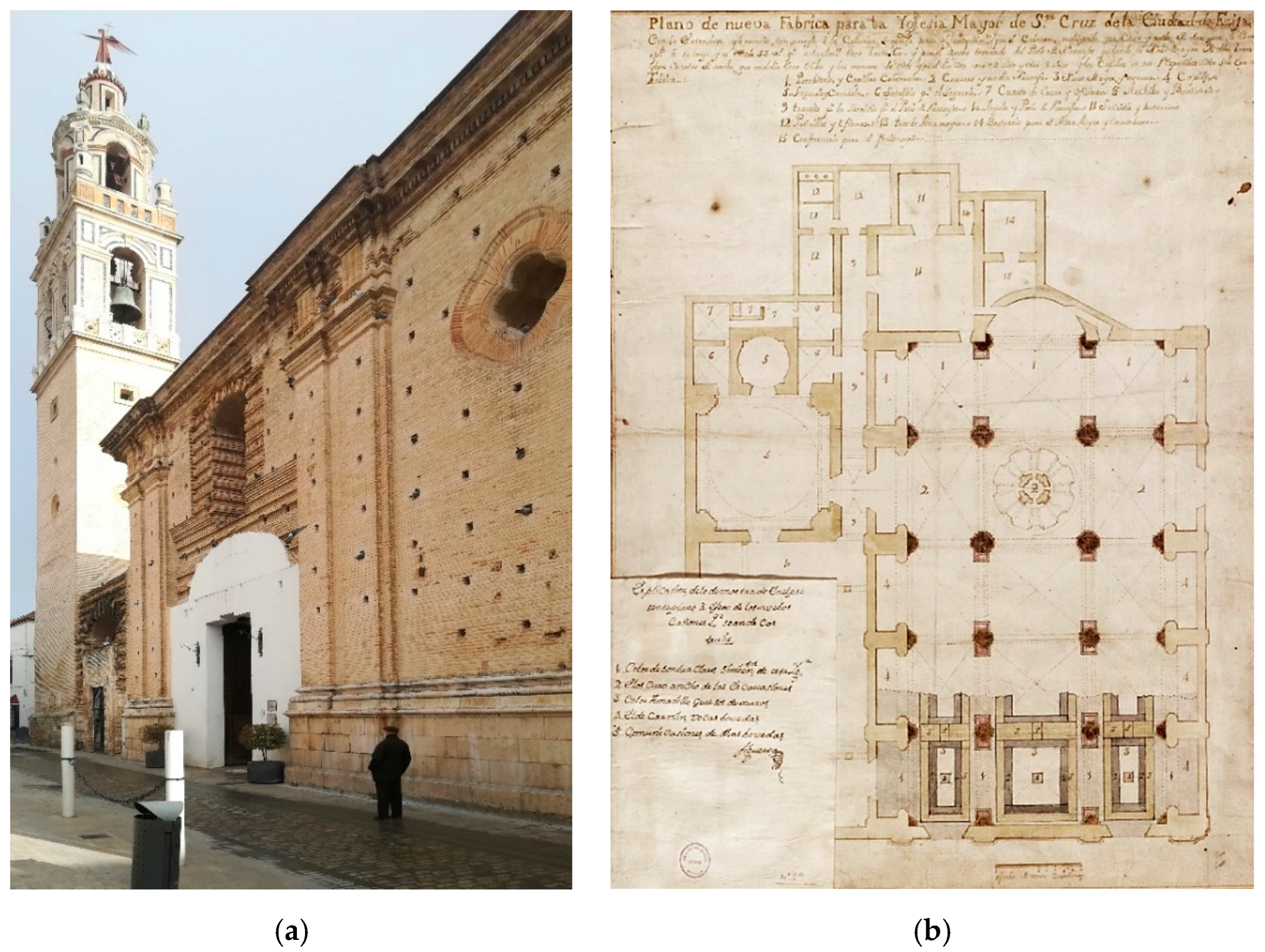
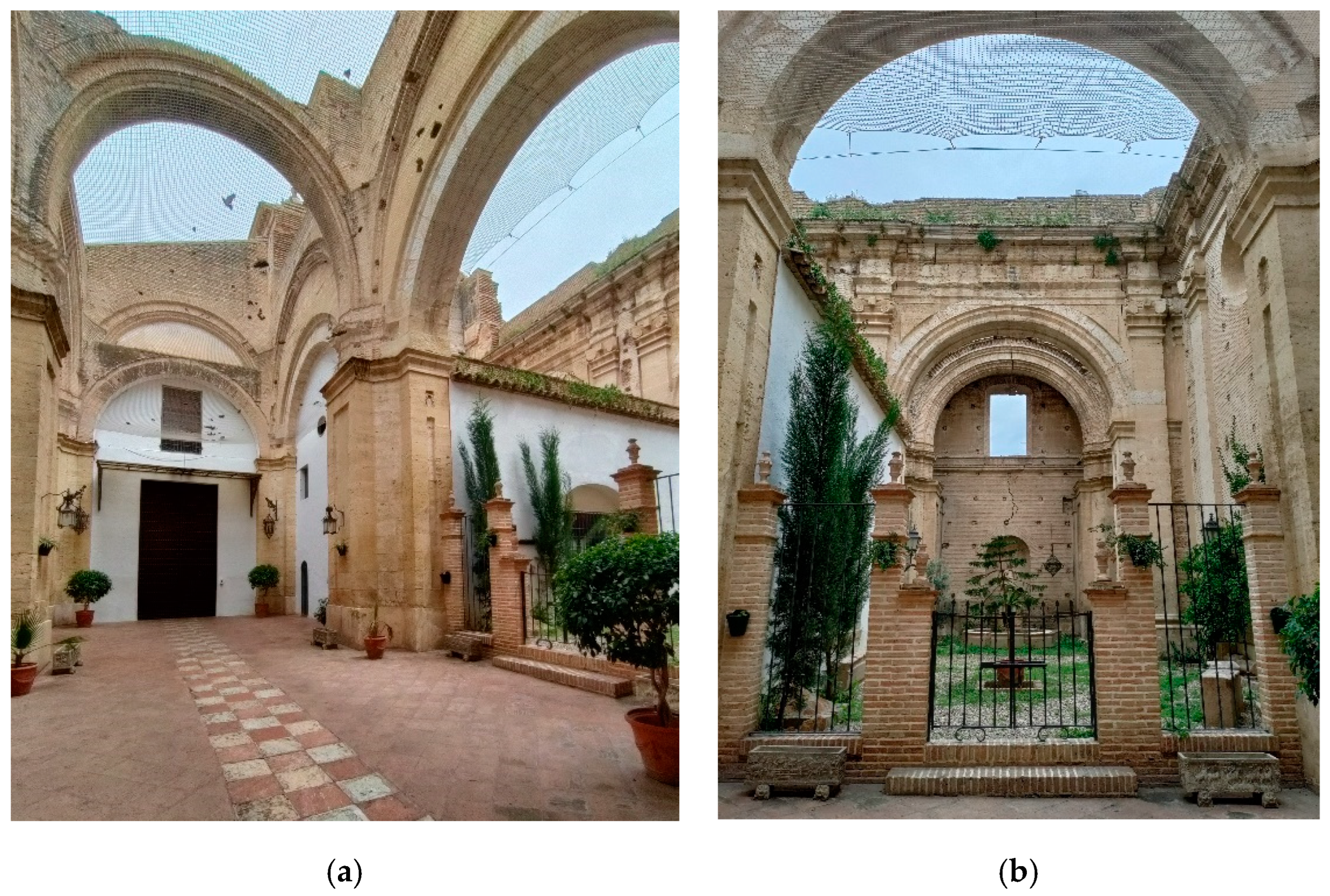
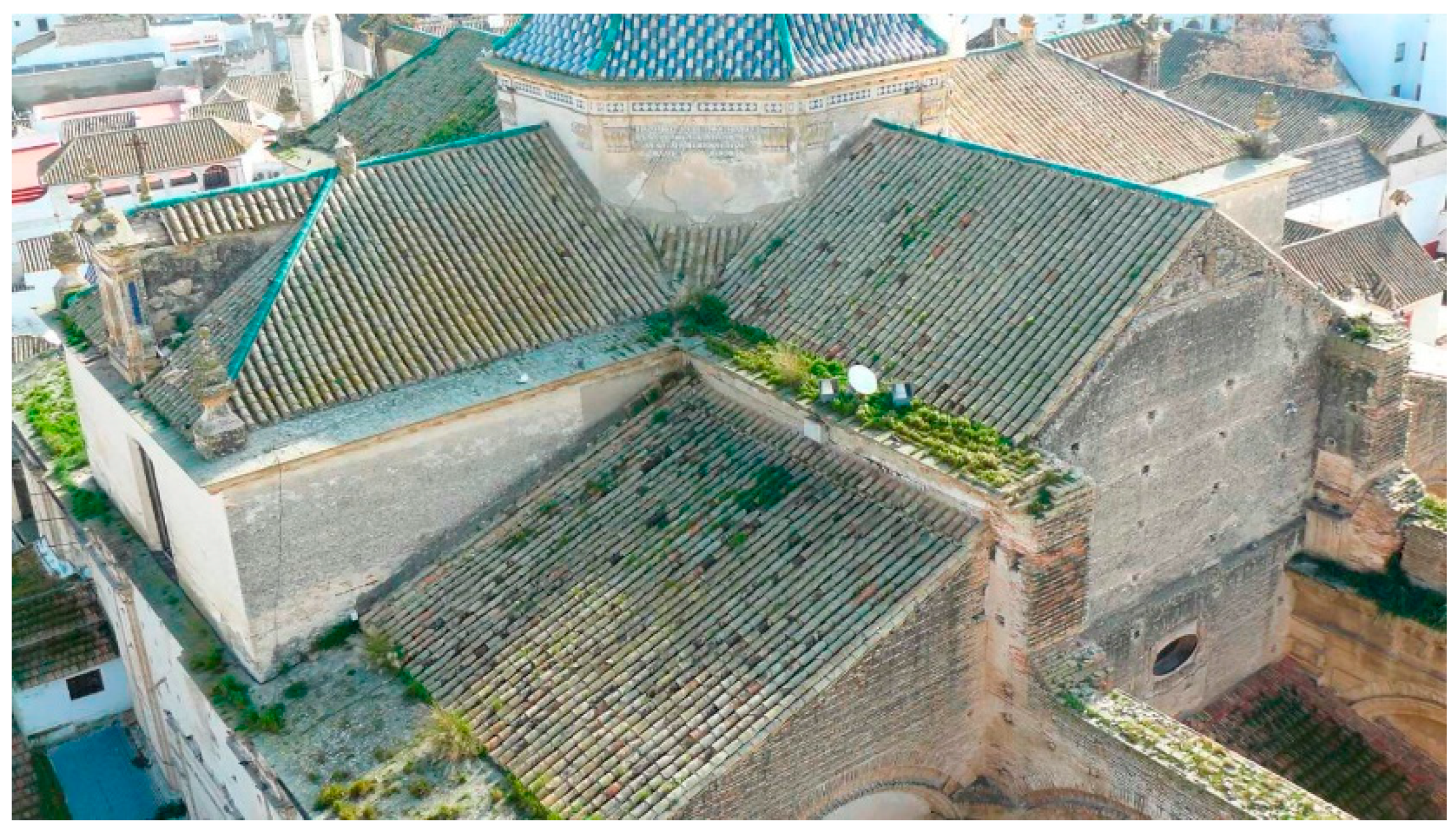
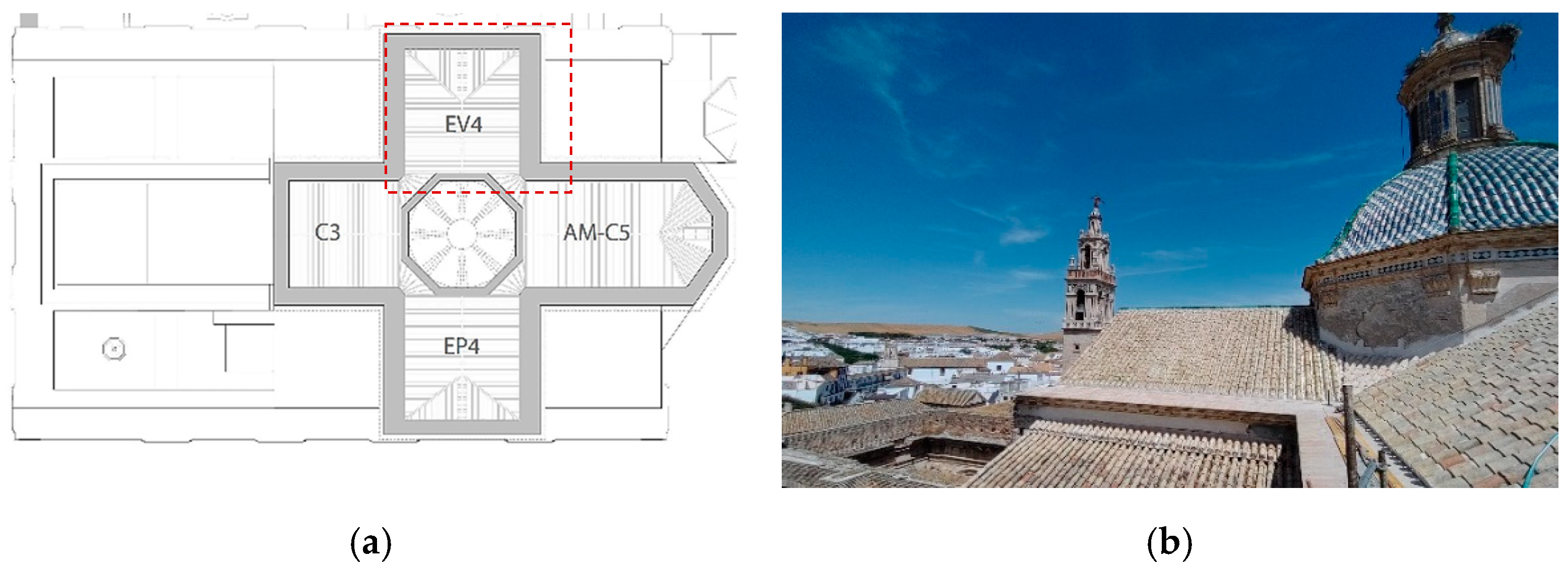
2. The Case Study: Santa Cruz Church

To carry out this study, we have taken advantage of the course of repair work on the roofs of the Santa Cruz Parish Church in Ecija, a town in Andalusia (Spain) (location (WGS84): 37.543, −5.080).
The building object of this study is the result of the cultural evolution suffered by the town of Ecija throughout its history. Some indications [59] suggest that the primitive mosque of the Muslim era was placed where the Santa Cruz church is located today. Later, on its remains, a catholic church of mudejar style was built, of which there is still some vestige [59]. According to historical documentation [60], this primitive temple was severely damaged by the Lisbon earthquake (1755); it was later demolished; finally, the subsequent construction of the current temple occurred, which has endured to the present day (see Figure 2a). Demolition and reconstruction work began in 1775, reusing part of the foundations of the previous construction.
The traces of the current temple were commissioned by Antonio Matias de Figueroa, although with contributions by Jose Alvarez [60]. The new construction was proposed as a large rectangle of neoclassical style with three longitudinal and five transverse naves (see Figure 2b). The construction process was very long and eventful; there were numerous constructive and structural problems: movements in the foundation, opening of walls, disaggregation of mortars, and rotting of the woods. In addition, there were disagreements between the different master builders. This gave rise to continuous interruptions of the works, as well as changes in the original traces. The works were terminated in 1836 when it was decided to end the temple with three of its transverse bays covered and to leave the first two uncovered, giving rise to an open space in the form of an atrium (Figure 3a,b).
Thanks to this process, the parish of Santa Cruz currently stands as a large rectangle (see Figure 4) with all its main walls, arcs, and pilasters raised, but not all are covered. Nine of its fifteen original sectors are dedicated to worship, which possess a sloping roof cover with a timber frame structure that surrounds the central dome of stone, and all are covered with Arabian roof tiles. These roofs are located at an altitude of between 13.20 and 18.55 m without any access to them, making their maintenance and cleaning very difficult, as observed in Figure 5.
In 2018, problems were observed on the roofs that posed a threat to the stability of the structure. In a first inspection, the structural wooden frame presented very degraded and semi-collapsed areas. For this reason, an emergency action was ordered and the development of a master plan to address this and other interventions that the building demanded.
Due to the urgency of the state of the roofs, the intervention proceeded, and it was during course of these works, beginning in July 2020, that the access and inspection facilities led to this study’s occurrence.
The roof has a traditional timber frame structure with a rafter-collar beam system (see Figure 6a,b). This typology is widespread in the Andalusian region. It consists of a pitched roof that has two slopes that converge on a ridge line, called a ridge beam. In addition, a series of parallel beams supports roof sheathing, which is called rafter. All rafters range from the ridge beam at the top to the wall plate at the bottom, which rests on the stone wall and is parallel to the ridge beam. At a third of the height, the rafters are joined with smaller pieces, the collar beams, and compensate for the deformation produced by the weight of the roof sheathing. This frame is located in the spaces under the roofs (see Figure 7), which are separated from the church by a thin suspended vault made of bricks.
There are different ways to solve the joint between the rafters and the wall plate and the support of these on the wall. The literature [19,62] shows us how medieval builders made details of this joint because it is one of the critical points of these structures. In this, it has been solved with a wall plate that rests directly on a square made on the upper face of the stone wall that discharges the rafters on the wall plates. This constructive solution, although it is very simple to build, entails a problem, which is that the wall plate is set with two hidden faces. These faces are recessed against the wall and are neither visible nor ventilated, which, as seen below, hinders their inspection, maintenance, and also contributes to the appearance of humidity.

3. Materials and Methods

3.1. Scope: Implementation of the Methodological Framework in the Case Study

The repair works carried out in the Church of Santa Cruz addressed the intervention in four roof sectors (EV4, C5-AM, EP4, and C3) (see Figure 8a,b). EP4 was the first to be restored because it was severely damaged and at risk of collapse. The other sectors underwent tasks of conservation, repair, and replacement with the intention of avoiding future problems arising from the deterioration of the structural elements.
The present study focuses on the EV4 area, a sector that was found to be unchanged at the beginning of this investigation, enabling the collection of data and comparison with what was observed in the intervention of the other sectors, in addition to the subsequent intervention in the study area itself.
Therefore, the approach is to propose a process to obtain data on the constructive and structural behaviour of a structure, as well as on the state of conservation of its elements. In this manner, we are able to know the pieces’ structural utilization ratios, which indicate the safety level (by obtaining the safety factor (SF)) of the entire structure, which facilitates decision making in elucidating the need or not of an intervention on a historical structure, without the requirement of destructive tests. By collecting data, thanks to the implementation of NDT, and with the processing of these data in a structural calculation program, relevant information has been found on the state of conservation and safety of the studied set.
These results have been validated by what was observed in the course of the work, where, due to the advance of the great deterioration of the elements, several materials retrieval had to be made and several structural elements replaced. This enabled us to study and observe structures similar to those studied at different levels of progress in deterioration.

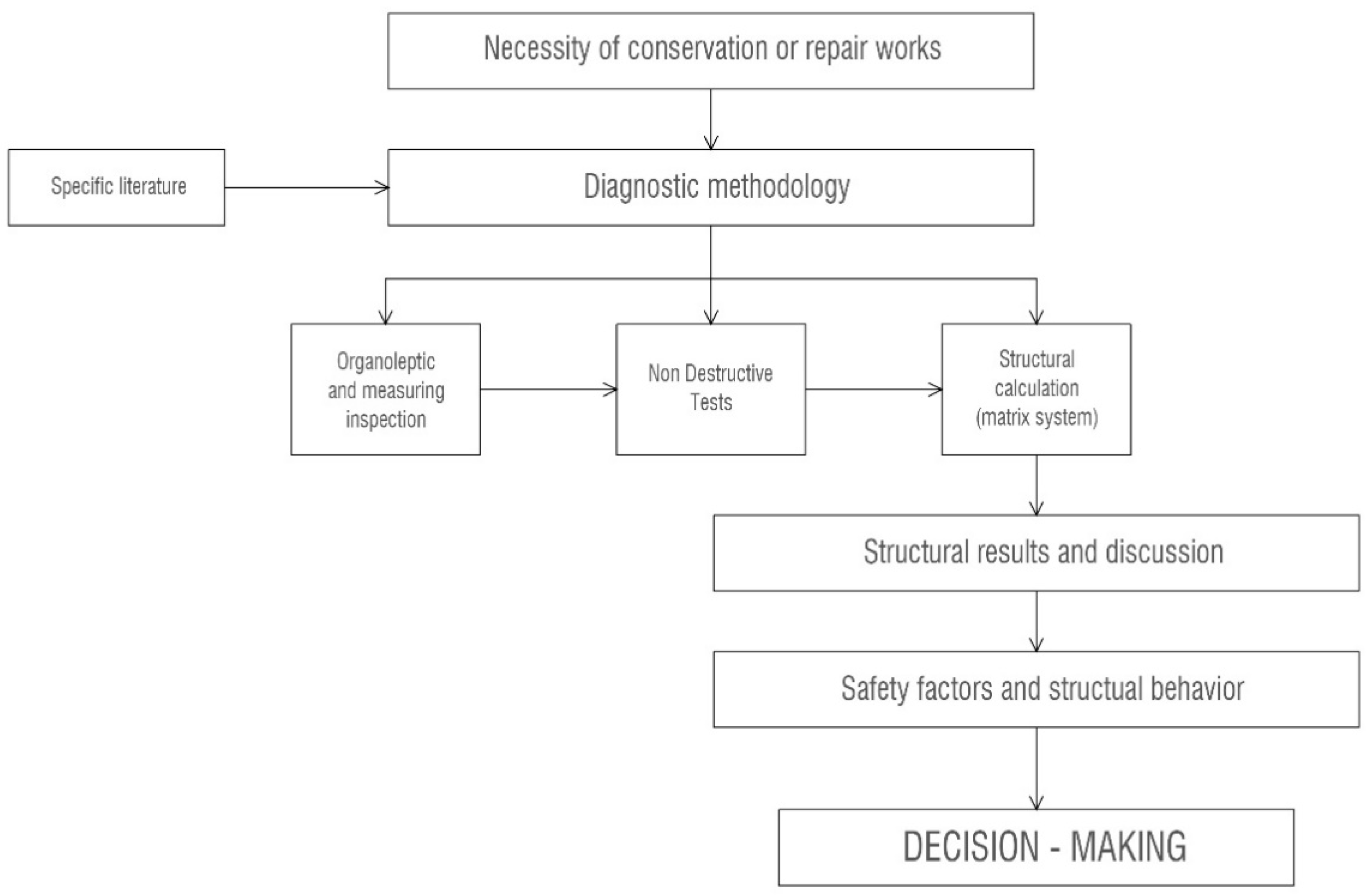
3.2. Methodological Framework

The method of analysis (Figure 9) of the timber structure under study was then launched and consisted of the following:
  • Organoleptic inspection: First, a visual inspection was carried out to determine, in a preliminarily manner, the state of the structure.
  • Measurements: The possible deformations of the elements of the structure were measured with a digital inclinometer and a laser meter to check some possible risk indicators.
  • Application of NDT:
    -
    Resistography allowed knowing the state of the internal parts of the elements against the wall.
    -
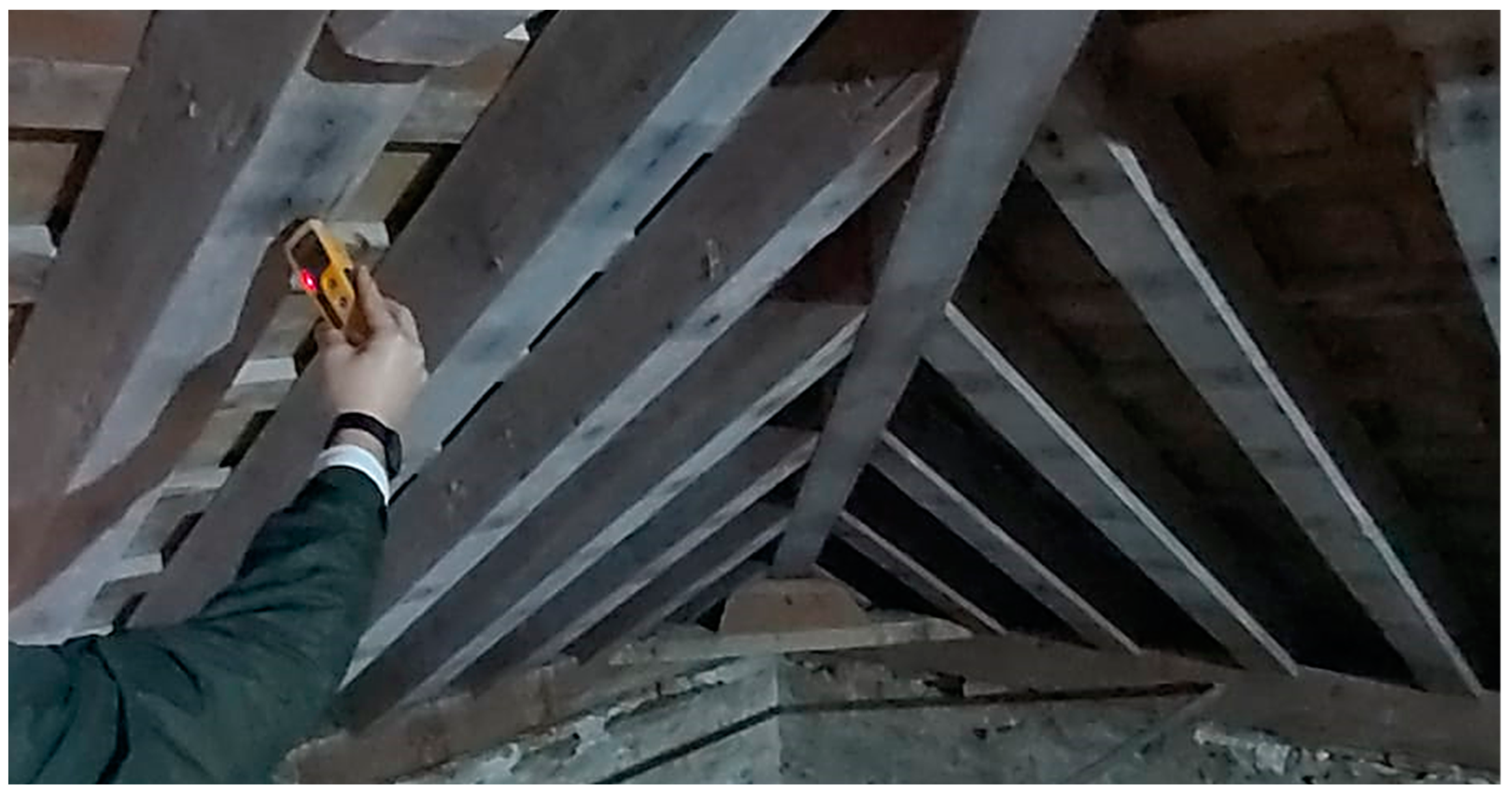
    Thermo-hygrometry: Temperature and humidity were recorded, as well as the hygrometry of the timber pieces.
  • Modelling and structural calculation: Data were transferred to the calculation program.
  • The analysis of the results provided decision-making outlines for refurbishment processes.

3.2.1. Organoleptic Inspection

First, a preliminary visual inspection was performed. The purpose was to obtain a global idea of the state of the structure and the attic space. This first visual search involved the finding of damage areas, moisture-affected elements, or large displacements. In conclusion, by the naked eye, we obtain general knowledge about the damage level. For this purpose, statistical incision sampling was also conducted with a manual punch.

3.2.2. Measurement of Possible Deformations

Data were taken on the relative position of the elements that make up the frame, as well as possible existing deformations.
To make these measurements, a laser distance meter and a GLM-120C Bosch digital inclinometer model were used. This equipment was calibrated according to the manufacturer’s instructions. It has a measurement range of between 0.08 m and 120.00 m, with a degree of accuracy of ±1.5 mm/m. Measure inclinations in a 360° range with an accuracy of ±0.2°.
In addition to the case study sector (EV4) measurements, previously, other similar but more damaged sectors (EP4 and C5-AM) were measured. These provide important data about different state of damage advances in similar structures.

3.2.3. Application of NDT

  • Resistography.
To obtain data on the state of the wood inside and the hidden faces of the wall plates, the resistography test was applied to obtain information on a sensitive point of possible moisture accumulation [39] and xylophage attacks [33].
The operation of this test is quite simple, it is a drill with a thin steel tip of 1.5 mm at the stem and 3mm at the tip. This drill bit rotates and advances at a constant speed, passing through the wood and measuring the electrical power that the system needs for it. In this manner, it is possible to observe pieces with up to a single visible face and to observe the integrity of its interior, detecting alterations in density, galleries, or soft matter. This provides data on their inner physiognomy. However, as explained in [36,41], it should be noted that the resistography test is a specific test that analyses the dimension of the hole, so discontinuous information samples are obtained that can in no case be used to positively validate an element. On the contrary, when detecting negative alterations or imperfections, it determines the time to reject the pieces or weigh their intervention [43].
For this study, an IML RESI F300 equipment was used, with a rotational speed of 1200 r.p.m. and a constant advance of 30 cm/min. The equipment generates a depth/resistance graph that shows the penetration resistance offered by the inspected part at each point. It has a penetration range of 10 to 1000 mm with an output graphics resolution of 0.02 mm/300 mm.
  • Hygrothermal study: Moisture test by electrical resistance.
In order to know what the expected hygrometric conditions of the structural timber under normal conditions were, the air equilibrium relative humidity (RH) was calculated, taking into account the extreme environmental conditions at the attic under the roof sheathing. Thus, the expected maximum and minimum RH of air were obtained. Then, using the specific wood hygroscopic abacus [63], the equilibrium moisture content (EMC) of timber can be calculated. This is the natural moisture absorbed by timber only under the influence of air humidity. At this point, historical climate data from Ecija city are needed. They were extracted from Climate-Data [64], are shown in Table 1.
These values correspond to the climatic conditions of the outdoor environment, but although the roof attics are ventilated, their interior conditions are not the same. To know the hygrothermal conditions inside the attics, a hygrothermal datalogger was placed for four months making periodic measurements. On the basis of these results, it is possible to obtain the maximum, minimum, and average values of the indoor air RH. Then, a timber characteristic equilibrium moisture content (EMCk) can be established, as the typical maximum EMC value that timber could reach.
Accordingly, the usual timber moisture content (MC values under the EMCk value) provides information about how timber properties can be modified and even if they are under decay risks. According to [24], as the timber moisture content increases, mechanical properties decrease. This ratio is almost linear for MC of between 8% and 20%, attenuated to higher contents (see graph in Figure 10a). Timber that has reached its saturation point for a long period of time (MC > 28%) has diminishing mechanical properties by up to 40% over its dry state (MC = 8–12%) [24]. In addition, timber elements over 18–20% MC are at risk of xylophage attacks [22].
To obtain on-site real timber’s MC and not the theorical one induced by air humidity conditions, the MC by electrical resistance test was carried out. This is based on the relationship between the MC (so relative humidity) of wood and the electrical resistance [22] (Figure 10b). The test was carried out with Protimeter Surveymaster SM equipment, with a measurement range between 6% and 28% MC, a value above which it is considered saturated and with an accuracy for the temperatures of 15–25 °C of ±0.5 °C. The apparatus and the measurements obtained were calibrated according to the manufacturer’s instructions. (Figure 11). Several spaced measurements were performed on the different elements (wall plates, rafters, and collar beams) every certain distance, and this sampling was intensified in areas with visual signs of moisture or rot. Furthermore, the test was repeated twice, under different conditions outside the atmosphere.
In addition, indoor hygrothermal environmental conditions were measured on site to establish a relationship between the theoretical expected timber EMC (according to the RH of air), and the real measures taken with the MC by electrical resistance test. Differences between both may indicate unplanned liquid water contributions. For on-site environmental conditions, DOQAUS digital thermohygrometer was used, which performs measurements every 5 s, with a measuring range of −50 °C to 70 °C and 10% RH at 99% RH. It has an accuracy of ±0.5 °C and ±2% RH.

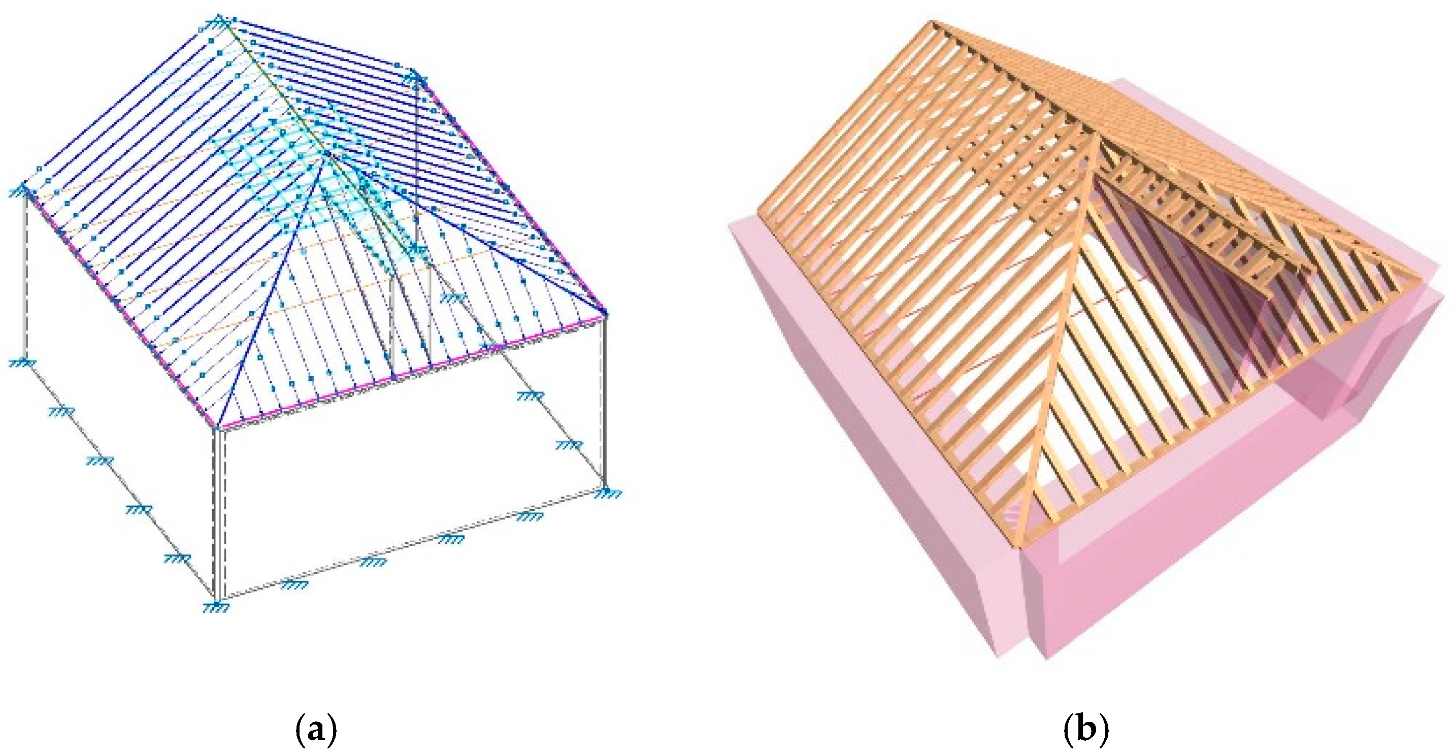
3.2.4. Structural Simulation

In this study, CYPE 3d software version 2021 [65] has been used, a matrix calculation software [57] specialized in bars and nodes. The structural method process is thus established as follows:
  • Original model construction:
First of all, the geometry survey is implemented over a CAD model by using the AutoCAD 2016 program of Autodesk [66]. Then, the three-dimensional CAD model of lines (beams) that converge in points (nodes) is elaborated by reflecting the timber frame according to the axes of its elements. This CAD model is exported to the CYPE 3d calculation program [65], where it served as the basis for model development. Inside the CYPE 3D software, lines and joints are transformed into beams and nodes. This is performed using the size and geometry survey.
The structural model will reflect the start inputs:
-
Original timber characteristics will be obtained by implementing the visual classification of timber elements [49,51].
-
Calculation conditions: Class of the wood service referred to in the regulations [51]. In this case, the structure is in a Class of Service 2.
-
Loads to be applied: Adapted to the existing construction materials in the case study and the related overloads contemplated in the reference code CTE [67]. The applied loads are shown in Table 2.
-
Timber structural safety parameters are provided by the structural Spanish code and implemented by the CYPE 3D parameters options.
This first structural model represents the starting point and unaltered point of the structure frame. Thus, the previous status provides the theoretical design conditions. This state is compared to the current status.
  • Current model construction:
The current timber conditions must be simulated in the structural model. For this purpose, a second model is needed with modified and current inputs.
Current status model inputs:
-
Timber elements modification sizes: These are obtained by the geometrical survey and organoleptic and NDT inspection results.
-
Timber conditions: These are obtained by the NDT data results and the literature knowledge implementation. It reflects the possible decay, moisture variations, or deterioration.
  • Calculation and comparison of results:
Once both models have been set, they are calculated by CYPE 3D software. Their results are analysed and compared. Therefore, the utilization ratios of timber elements are discussed, and the original and current safety conditions are compared.

4. Results and Discussion

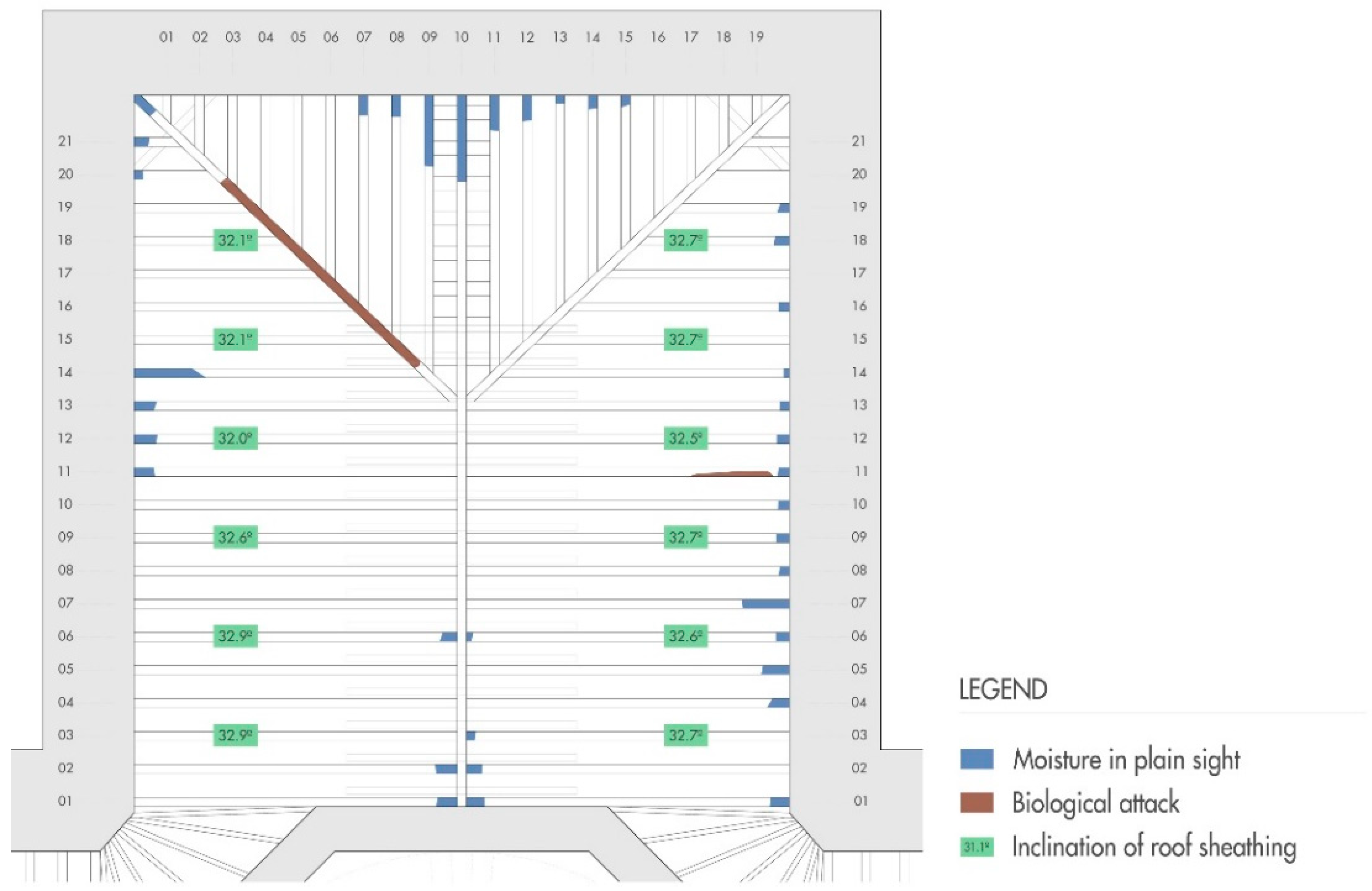
4.1. Organoleptic Inspecion Results

The EV4 sector structure had a lot of dirt, especially due to biological remains (pigeon guano, insects, and dead animals) (Figure 12a). The dirt, although widespread, accumulated in large deposits on the sides of the vault, in the gaps between the bracing partitions, and on the wall plates. The timber beams were covered with a patina of dirt that had accumulated over time. However, unlike other sections, no serious signs of deterioration were observed, and significant deformations were not observed, including broken or collapsed elements. There were certain areas: ridge beam points, some joint of the rafters with the ridge beam or with the wall plates (Figure 12b), and some wall plate sections, which presented active areas of moisture damage. Thus, almost 50% of the joints between rafters and wall plates seem to be affected by moisture, but with a nonuniform distribution. Only two pieces were affected by biological attacks, with actual nonactive termite signs. In addition, two small areas with signs of brown rot were found. Despite all this, the structure presented at first sight an acceptable condition, without risk to its integrity signs. The results of this first inspection are represented in Figure 13.
A statistical sampling was carried out through incisions with a manual punch. Penetrations of about 3–5 mm were obtained in most of the apparently healthy areas, while, in the areas that presented humidity damage or colour changes, penetrations of up to 17 mm were obtained.

4.2. Measurement of Deformations Results

Previously, measures had been made in other similar but more damaged sectors. In these areas (sector EP4 and C5-AM), significant deformations and displaced elements were discovered. An up to 11 cm deformation was found on the wall plate of the C5-AM sector; due to the lateral loads, the piece was displaced to the exterior.
In the area of the case study, the EV4 sector, no significant deformations or displacements were observed on the roof timber frame. In contrast to what happened in other sectors, the wall plates were perfectly aligned with the walls, the ridge beam only presented an almost imperceptible deformation, and the joint of the rafters occurred without major problems. The inclination of the roof sheathing, that is, of the rafters, was measured; it always possess values between 32° and 32.9°. The largest angular difference obtained was of 0.9°. In addition, no bending or torsion was found at the beams
The results of this measurement, as well as the results of organoleptic inspection, are represented in Figure 13.

4.3. Non-Destructive Tests Results

4.3.1. Resistography Results

Resistography perforations were made on some points on the wall plates that can be seen in Table 3. These were selected for presenting visible deformations, humidity, rot, or as potential points of structural stress concentration. Moreover, these pieces had only two visible faces. The results of the tests are in Table 3, and the graph shows the engine consume in percentage and the progression in cm. In all tests carried out, it was found that once the drill was introduced, the timber lost resistance to a depth of between 3 and 14 cm. This evidences the resistant loss of the analysed areas section. Although in most cases they had geometric integrity on the outside, the interior was found with severe alterations (rot or attacks by xylophagous agents attacks).

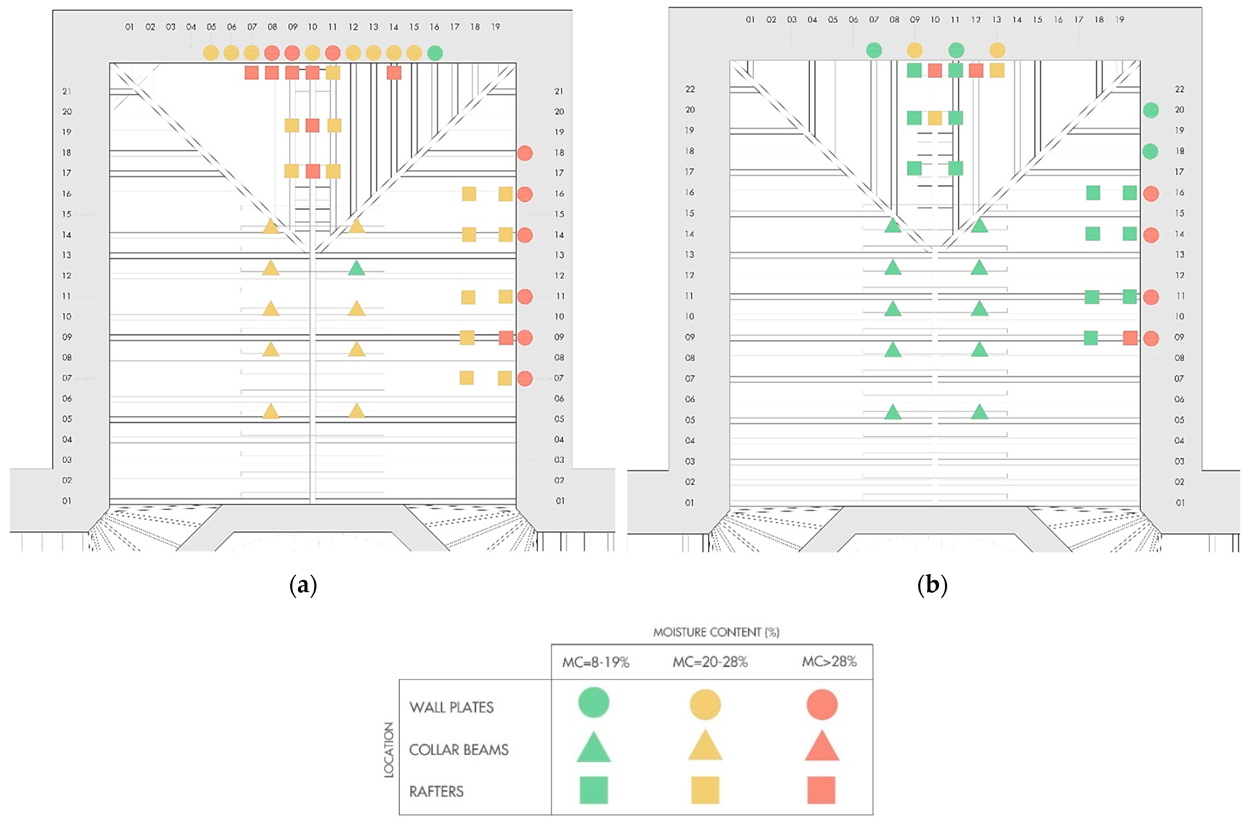
4.3.2. Hygrothermal Study: Moisture Results by Electrical Resistance Test

Attic hygrothermal data logger measures were taken for four months, from September to December, which is the wettest month according to [64]. The results show that the RH of the indoor air rarely exceeded 80%; thus, this value has been taken as a characteristic RH (RHk). Consulting the hygroscopic abacus [63], the EMC of the timber, when air RH = 80% is EMC = 18%, regardless of the temperature. This value has been taken as the characteristic equilibrium moisture content; thus, EMCk = 18% in the attics. These data are above the RH point recommended for timber of MC = 12% [22]. This means that it is expected that the elements reach moisture levels higher than those recommended in a timely manner, and this only takes into account the action of the air that surrounds it and not the possible direct water leaks. This can pose a risk to the structure.
To know the actual MC of the timber, the moisture content was carried out by electrical resistance test. The tests were performed on two days in different weeks. Firstly, on a rainy day after several days of rain and, secondly, a week later on a sunny dry day (without any rain for a week). The results of the test are shown in Figure 14a,b (first and second days of measurements, respectively).
During the first day, usually all measurements were above 20% MC. The collar beams, which are the most ventilated pieces, had values of between 19% and 24%. The wall plates were the pieces with the highest MC values, and they are, in many cases, above the saturation point (MC > 28%). In any case, most of the structural frame was in danger of attacks from degrading agents. During the second day, an average MC around 17% was obtained in the collar beams and 18% in the rafters. However, the wall plates continued to present numerous areas where the MC was above the saturation point not only in those that are visually wet.
Then, these results are compared with the timber expected EMC. This was obtained by measuring indoor on-site hygrothermal conditions. Their results are shown in Table 4. Repeatedly, they were taken on two different days.
It can be seen that the first day’s result is abnormally high, and a 19% EMC was obtained. This is explained by the extreme environmental hygrothermal conditions in the attics. However, most of the timber elements had even higher MC levels. However, the second-day result is perfectly normal at 12% EMC. Moreover, even some elements of the timber frame had higher MC values. Therefore, there are additional contributions of liquid water from leaks through the roof in this case.

4.3.3. NDT Analysis

During the preliminary organoleptic inspection, everything seemed to indicate that the structure was in good condition: No deformations or breaks were observed, the beams appeared to be fine and only some specific areas affected by moisture or alterations were found. However, when NDTs were applied, it was discovered that the structure presented high levels of theoretical and real moisture, especially in the elements of the wall plates.
Furthermore, by conducting the resistography test, it was known that at least some of the walls were deteriorated inside. Some perforations carried out in other areas and by the openings of small prospections executed in the repair works confirmed the suspicions. Indeed, the wall plates were, as indicated by resistography, decayed by rot inside. Between 40 and 60% of their effective real section had been lost (Figure 15).

4.4. Visual Classification

In order to obtain the resistant and mechanical values of the timber frame elements, all the pieces were classified according to the current visual classification index (in this case, the standard UNE 56544 [49] and the Spanish structural code: CTE-SE-M [51]).
The wood of the structure was recognized as Pinus Sylvestris L. species (Scots Pine or Flanders Pine). The classification was made according to the procedure for “large dimension structural wood” (MEG by his Spanish acronym). The frame was inspected, in which the possible particularities or defects included in the standard were piece-by-piece recorded: knots, checks, biological alterations, etc. The results of this classification can be observed in Figure 16.
Of a total of 79 pieces, 11 were rejected, which represented 14% of the total. Among all rejections, more than half were due to the presence of knots (54.5%) (Figure 17a), while checks were 36.4% (Figure 17b) and biological alteration was only 9.1%. It should also be noted that 33% of total of the collar beams were rejected according to these standards. This, together with the general analysis carried out for the classification, shows that pieces of worse quality were used in the execution of these timber frame elements in the original construction.
The remaining 86% of pieces passed the required quality standards and could be classified as MEG wood (suitable for building structures). On the basis of the knowledge of the species and the wood quality data, following the Spanish code [51], it was possible to obtain the pieces (Resistant Class). For Scots pine, with MEG quality, a C-22 Resistant Class is assigned.
This indicates the mechanical characteristics of the timber beams according to the Spanish Construction Code (CTE) [51]. Therefore, the pieces that have not passed the quality filter of the standard would be rejected. This would make sense in the case of erecting parts in the new building [45], but in the case of inspection of existing structures, it is not logical to reject pieces, as it is proven that they are structurally working [26]. In this case, the particularity was more remarkable because one of the rejected pieces was a main ridge rafter (Figure 17c) that collects the joints of numerous rafters reaching the ridge beam and configuring one of the main lines of the structural frame, which shows its good behaviour as a bearing piece to consider.
That is why these pieces have been assigned with the lowest of the Resistance Class contemplated in the CTE: C-14. In this manner, they are considered in the transmission of force, but with a lower resistance than the optimal parts according to the quality parameters.

4.5. Structural Simulation Results

4.5.1. Original Model Construction

The surveyed geometry has been transferred to a CAD file, using the AutoCAD program of Autodesk [66]. This model was exported to the CYPE 3D calculation software [65]. Its geometry has been modelled as a structure of beams and nodes, which has been configured as observed in the real structure (Figure 18a,b). The beams have been modelled as bi-supported elements in which all joints are articulated [68].
The original timber features have been assigned following the visual classification results (Figure 16).
For the calculation conditions and the structural safety parameters, the model and its elements have been configured according to the required parameters included in the current code (CTE) [51,67], which has been taken as a reference: bending limits, lateral bending limits, buckling and lateral buckling.
The applied load can be seen in Table 2, taken from the indications of the structural code.

4.5.2. Current Model Construction

The NDT and visual classification results have provided data on the condition and affections of the structural elements. These, to a large extent, reduce the timber’s original characteristics, and the decrease in its mechanical values must be considered in the model to truly know the current level of safety offered by the whole. In order to be able to distinguish different areas within the same bar, for example, with higher or lower humidity, they have been divided in length. Therefore, it is possible to discretize their characteristics as obtained in the visual classification and MC plan (Figure 16)
Based on NDT data and previous research methodologies [9,24,27], reductions have been applied to the characteristics and sizes of the original wood. Therefore, these resistance losses can be simulated in the calculation software (Table 5).
These reductions are the completed inspection’s results. The motives and the transformations made are explained below:
  • General slight loss of surface density: By means of the punch test, it has been quantified at an average depth of 3 mm of perimeter shape in all pieces, in line with what was published in [26,27] (except the wall plates that will be seen later). Therefore, new dimensions have been assigned to the beams, reducing by 3 mm on each face.
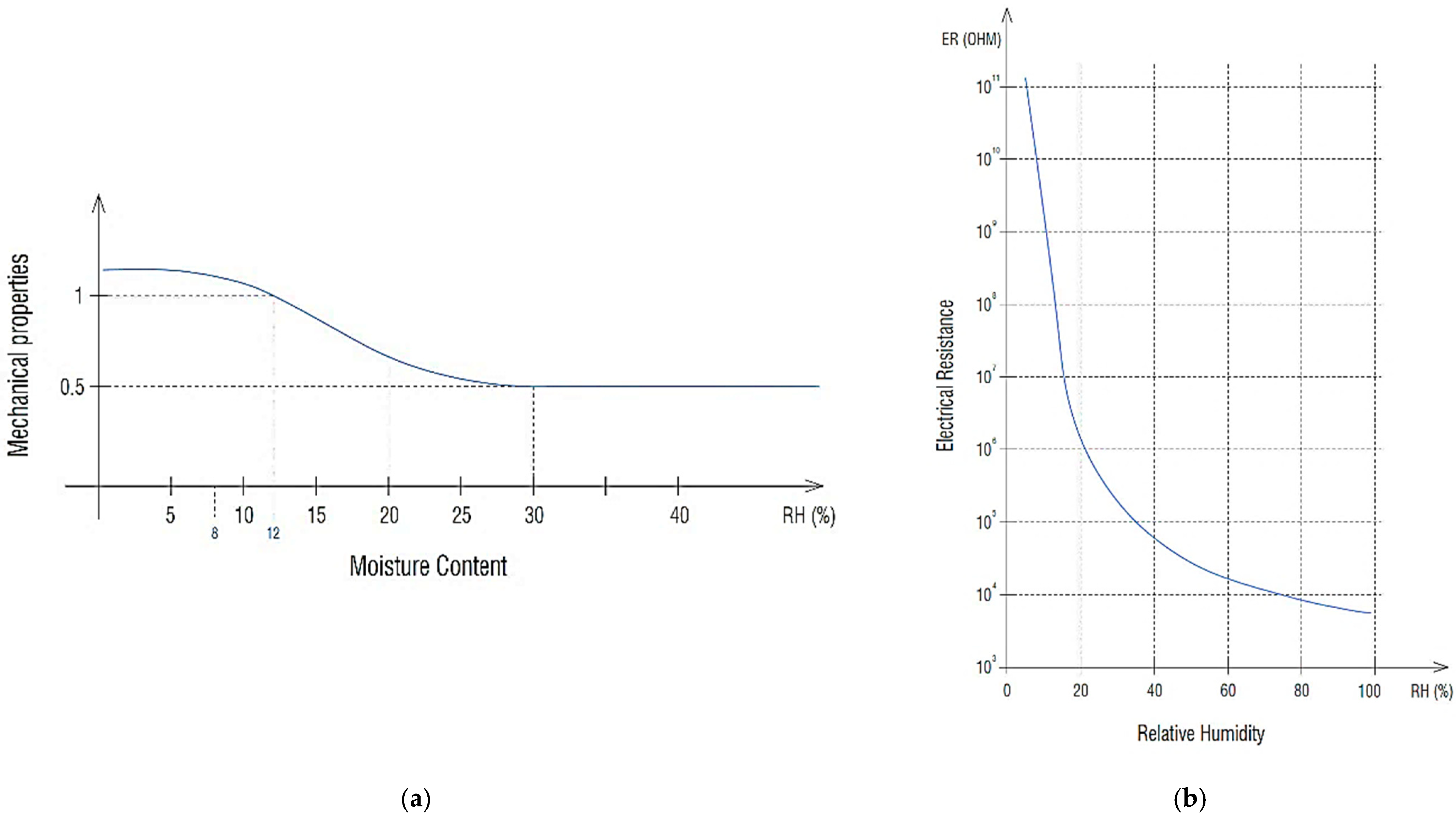
  • General high humidity: According to the hygrothermal study carried out, timber can reach the value of MC = 18% at different times of the year. This leads to a resistance loss of up to 30% in relation to a timber MC = 12% conditions [24]. To simulate this characteristic loss and following the indications of the reference code [51], all timbers have been reassigned to a C-14 Resistant Class. Then, always according to the code, their mechanical characteristic values are 30% lower than those considered for the C-22 Resistant Class timber. In this manner, a generalized 30% properties decrease has been simulated in all elements due to the action of their high MC levels.
  • Rafters, high moisture contained in a localized manner: In certain areas of some rafter, the observed MC rises up to 20–24%. For these values, the losses of mechanical properties are up to 35% over the originals at 12% MC [24]. The properties of all beams have already been reduced by a general margin of 30% by reassigning them as C-14 timber classification. To consider the additional 5% (35–30% properties loss already applied), it was decided to reduce the most MC affected beam area dimensions. The equivalent section has been calculated as 95% of the originally contemplated one, leaving a final rafter’s dimension of 12 × 16 cm applied into the affected areas.
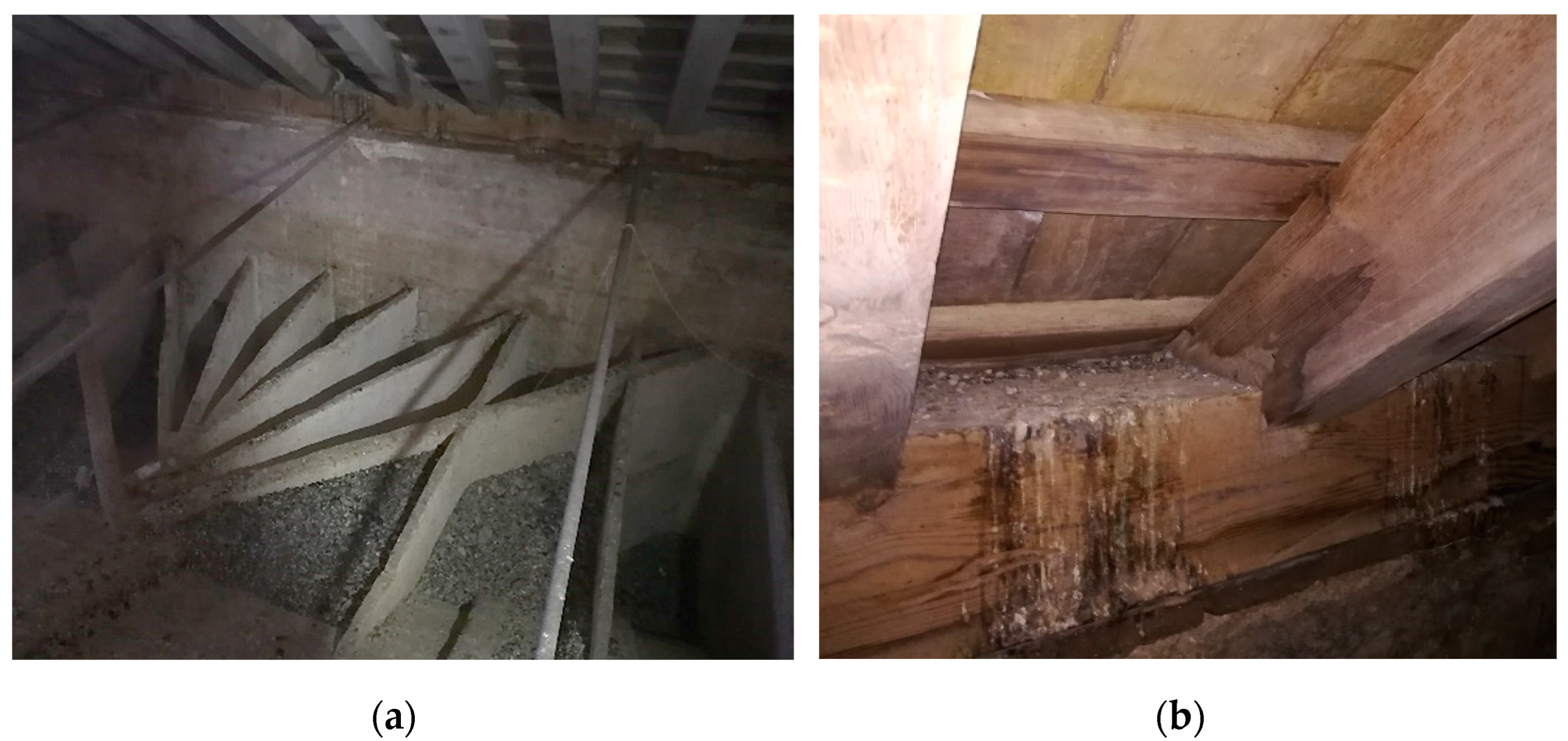
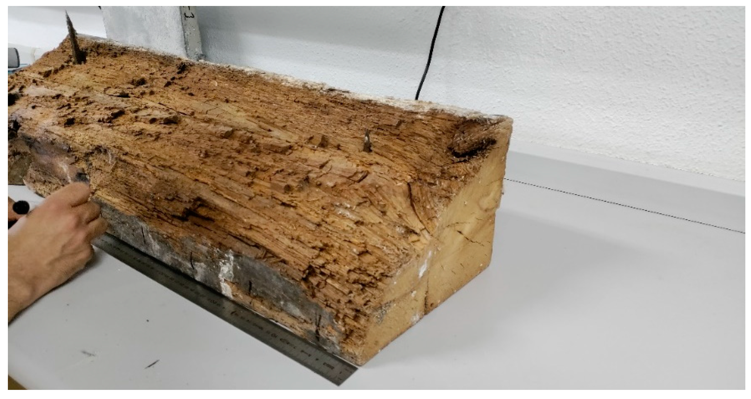
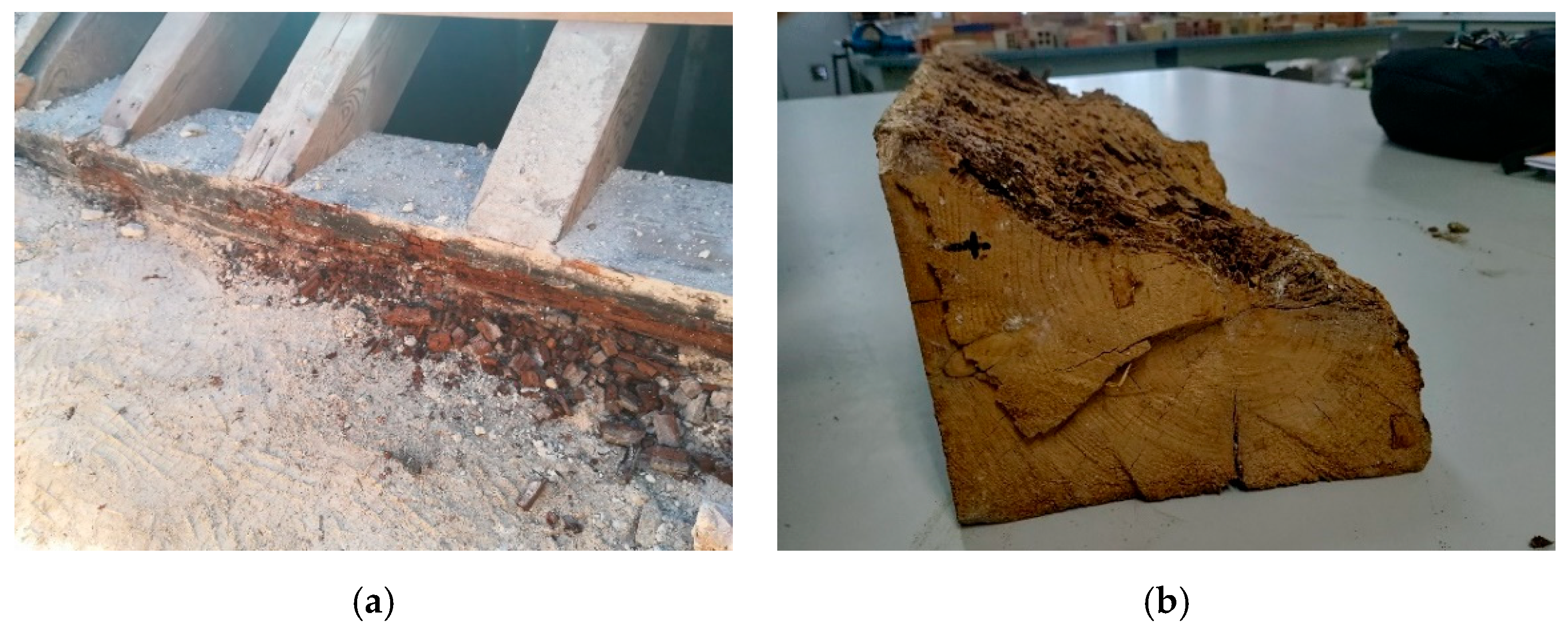
  • Wall plate-lost section due to decay: As obtained in the resistographies made and corroborated by the prospections, the wall plates have lost on average 50% of their effective section due to rot (Figure 19a,b). To simulate this, an effective section half from the original one has been transferred to the modelled beams.
  • Wall plates, saturation of still healthy wood fibre: The remaining wood that has not rotted has a high MC above the saturation point (MC > 28%) Again, according to [24], saturated timber has lost up to 40% of its mechanical properties compared to one with a standard MC level. To simulate this reduction, the wall plates had already been applied by the C-14 Resistant Class (which makes a 30% reduction) and the effective section reduced by an additional 10% (on the section already reduced by half because of rotting). In this manner, simplifying to a square shape, the final dimensions of the wall plates have been configured with 15 × 13.4 cm.

4.5.3. Calculation

Both models, previous and current status, were set to calculate and obtain results from the CYPE 3D 2022 structural software. The previous status model has no complexity; however, the current status model presents a critical sensitive point to consider. This point is the joint between the rafter beams and the perpendicular wall plate, which is supported on the wall. The massive stone walls represent a confinement element that practically fits the timber frame. This could represent a problem when calculating the current structural state that provides added rigidity to the structure because the massive stone walls restrict the possible lateral displacement. Thus, even if the structure was deteriorated and the wall plates rotten, the wall link will contain the frame and counteract with the displacements. Therefore, two hypotheses have been set to be able to analyse the current resistance utilization ratios and the possible displacement without taking the wall into account.
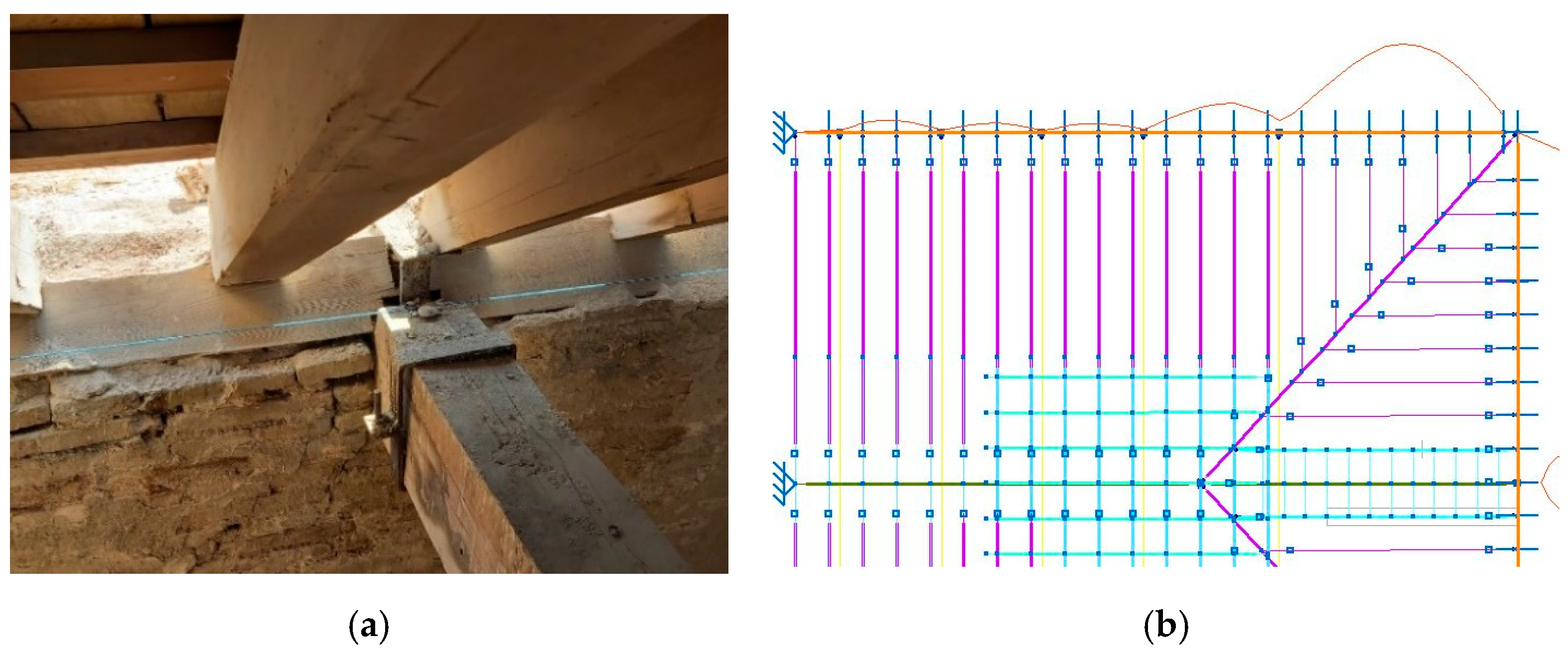
  • Hypothesis 1: (Figure 20a) The timber frame and its wall plates rest on the wall. It has been modelled as a structural sheet; a rigid element in its plane that can be characterized according to the parameters of the existing wall [68]. In this manner, it is possible to observe the most reliable behaviour with respect to the structure, in which the resulting thrust of all the elements rests on the wall plates and solidarity on the walls. This means that there are no significant lateral displacements of the whole. However, this hypothesis does not consider the possible internal deformation of the section of the wall plates, which is considered a dimensionless bar. To also contemplate this possibility, the second hypothesis has been modelled.
  • Hypothesis 2: (Figure 20b) In order to reproduce the structural behaviour, if wall plates sections deformations occur, the structure has been modelled without the external link of the wall. This had previously been already observed in other sectors produced by the rotting of the pieces. Therefore, to this end, the supports of the wall plates have been configured as supported external links, but with only one degree of freedom of movement in the rafter beam direction. In this manner, if there are resulting efforts from lateral thrust, it implies the wall plate’s rigidity and the tie beams coercing the movements. Therefore, the tie beams were responsible for withstand those thrusts, as if there were no walls. This allows the study of wall plates displacement behaviours, a critical piece of this structure, if the internal rot leads to deform it to the point that its inner face moves as if it were not linked to the wall.

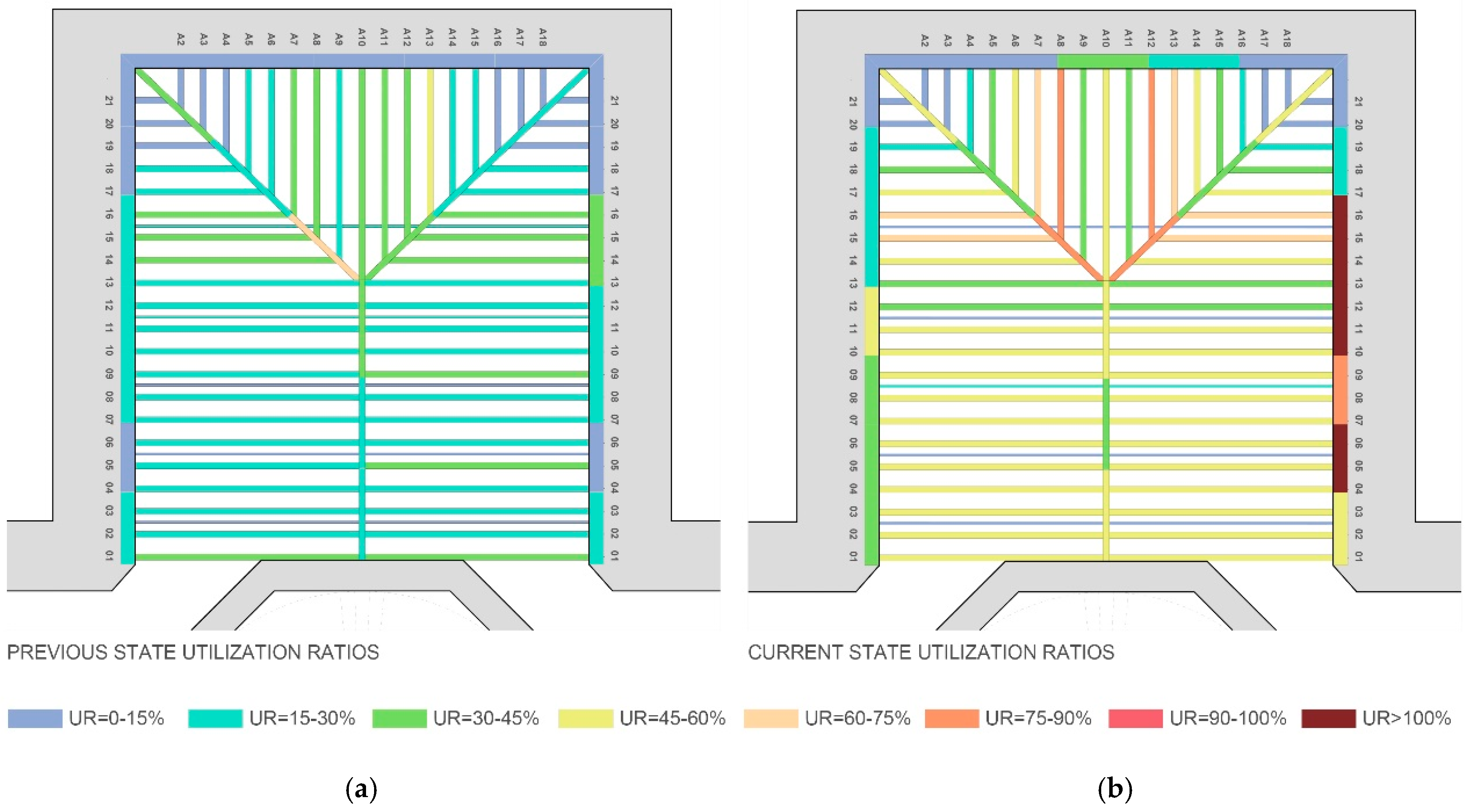
4.5.4. Results Comparison

At this stage, structural results can be obtained and compared. When the previous and current status is compared, structural performance changes and damage evaluation can be observed and discussed. For this purpose, the previous and current structural utilization ratios (UR) are shown in Figure 21. They have been considered as the most representative values of the structural situation of the element and, in the same way, their safety conditions. To clarify, Figure 21a represents the previous status of the structure without any modification or damage or alterations. While Figure 21b represents the current status of the structure, this is observed with the wall link in hypothesis 1 by obtaining the actual frame contention state. Both models represent the most damaging loads combinations, in this case, with wind loads applied from the left to the right side.
On the other hand, the collar beams have not been represented because they do not have representative values. Their previous status UR is always less than 8%, while for the current status, it is less than 15%.

4.6. Discussion

Software calculations results allow quantifying the behaviour observed in the timber structure sector under study. These results are also compared to the other similar church sectors.
On the one hand, considering the previous status, the timber structure was, in origin, widely oversized. Practically, all beams have a UR below 45%. Moreover, most of them are under 30% UR. After the damage observed in the other sectors, this oversized structure could be one of the reasons why the structure did not collapse.
On the other hand, considering the current status, a higher UR was obtained. Most of the rafter beams reach 45–60% UR, while some specific pieces near the mean node at the ridge beam reach a 75–90% UR, almost wasting the structural timber section. Moreover, some sections of the wall plates, in the convergence with rafters and tie beams, have reached a UR higher than 100%. Therefore, their sections are overloaded, even, one point has a 130% of UR. This would mean that theoretically the timber element cannot withstand the tensions that reach it. Thus, the section would begin to crush, leaving everything contained by the massiveness of the wall (Figure 22a).
Based on structural Spanish regulations, the safety factor in case of failure (ELU by Spanish acronym for Ultimate Limit State) has been measured [51]. For the previous status, considering the main elements, a 3.5 safety factor has been obtained. This means that the structure was designed three and a half times above this failure situation. Then, the same safety factor was obtained but with the current deteriorated status. Despite applying the quantified structure deterioration, a safety factor of around 2.1 is obtained. That is, the structure as a whole, in its current state, is not subject to risk of collapse. However, it has been verified that the main risk of the structure occurs in certain localized areas of the wall plates as local severe damage.
Taking into account the lateral deformations, if only the roof sheathing loads are considered, a small bending in the rafters is obtained, which with the action of the wind load would increase up to 15 mm, which is within the admissible levels. On the other hand, considering the displacements of the wall plates, when the wall link is considered, the deformations are almost negligible. However, to check the timber frame stability and the capacity to contain the rafter thrust, hypothesis two has been considered. Then, if the binding action of the wall is not considered, the displacement of the wall plate would suffer (Figure 22b). In this case, if only vertical loads are considered, the structure as a whole would remain almost without deformation, with a side bending of 9 mm at the wall plates. However, if the lateral wind load is considered, in the current status case and without the wall link, unaffordable deformations of up to 120 mm would be reached.
In the real structure, these thrusts are finally supported by the walls, but considering the wall plate’s deterioration conditions, this will lead to a progressive crushing of the section, as already observed in other damaged church’s sectors.
These outputs provide important information about the timber frame’s structural behaviour as well as the safety level and critical points. At the first step, the literature noted the importance of knowing the timber real state, mostly when some faces are hidden. The danger of water and moisture is a general topic at the historical timber interventions literature. In this study, by conducting an organoleptic and NDT survey, it was possible to achieve knowledge of the timber pieces’ current status.
The calculation simulation carried out, following the existing literature, has been a necessary tool to confirm and quantify the deterioration observed and to know how the structure’s safety was affected. The numerical results support the hypotheses set and the behaviour observed in other church’s sectors with higher deterioration levels. Thus, it can be stated that this simplified ND and structural assessment methods of the approach to the real state and safety conditions of the historical timber frames are confirmed.

5. Conclusions

The importance of NDTs has been reaffirmed when a historical timber structure, as well as their application, is surveyed, based on the specialized literature. It is the best way to obtain real knowledge of the whole without increasing the damage that the structure already has. For this purpose, this diagnosis method has been established considering the entire decision-making process that architects must face in this type of repair works.
Another important conclusion to be pointed out has been the quantification of UR and the safety factor, which is required to quantify structural utilization or eventual oversizing factors. At those times when calculations were not possible, designing the elements with major dimensions that could be thought a priori was the method to provide the whole with security in unexpected cases or eventual deterioration. Therefore, despite the damage already suffered by the pieces, the safety factor obtained for the main beams is still around 2.1 times its critical point.
However, the overloaded state of some wall plates areas was also observed, for which its failure could lead to progressive total collapse of the timber frame. This leads to another conclusion about the importance of constructive detail, especially in carpentry and timber construction. The definition of these details was already available in the medieval carpentry manuals (Figure 1b), where the correct situation and ventilation of all pieces are shown as a vital factor when designing these types of structure. The decay caused by moisture due to the lack of ventilation of the wall plates hidden faces has been demonstrated to be the most important structural stability risk. Therefore, the construction detail, the pieces’ placement, and the maintenance lack, are sources of the risks, and do not include dimensions, natural progression of time deterioration, or loads.
In conclusion, this study, by applying a few-step approach and including this new calculation process, makes it possible to deal with this kind or repair work in a more conscious manner and with better knowledge of the structure. Thus, this approach leads to greater efficacy with human, material, and economic resources. This is crucial considering that many historical structures remain unrestored and the resources to intervene them are limited.

Author Contributions

Conceptualization, J.S.-C., J.M.R.-C., C.R.-G. and C.G.-M.; methodology, J.S.-C., J.M.R.-C., C.R.-G. and C.G.-M.; software, J.S.-C. and J.M.R.-C.; validation, J.S.-C., J.M.R.-C., C.R.-G. and C.G.-M.; formal analysis, J.S.-C., J.M.R.-C., C.R.-G., J.A.L.-M. and C.G.-M.; investigation, J.S.-C., J.M.R.-C., C.R.-G., J.A.L.-M. and C.G.-M.; resources, J.M.R.-C., C.R.-G., J.A.L.-M. and C.G.-M.; data curation, J.S.-C. and J.M.R.-C.; writing—original draft preparation, J.S.-C., J.M.R.-C., C.R.-G. and C.G.-M.; writing—review and editing, J.S.-C., J.M.R.-C., C.R.-G. and C.G.-M.; visualization, J.S.-C., J.M.R.-C., C.R.-G. and C.G.-M.; supervision, C.R.-G. and C.G.-M. All authors have read and agreed to the published version of the manuscript.

Funding

This research received no external funding.

Acknowledgments

We are grateful to the SGI Fototeca-Laboratorio de arte of the Universidad de Sevilla [61] for the cession of Figure 2b: “Original plan of Santa Cruz church”.

Conflicts of Interest

The authors declare no conflict of interest.

References

  1. Candelas-Gutierrez, A. The Power of Geometric Relationships in Mudéjar Timber Roof Frames. Nexus Netw. J. 2017, 19, 521–545. [Google Scholar] [CrossRef]
  2. Querol, M.Á. Manual de Gestión Del Patrimonio Cultural; Akal: Madrid, Spain, 2010. [Google Scholar]
  3. The Athens Charter for the Restoration of Historic Monuments—1931. First International Congress of Architects and Technicians of Historic Monuments, Athens 1931. Available online: https://www.icomos.org/en/167-the-athens-charter-for-the-restoration-of-historic-monuments (accessed on 5 May 2003).
  4. The Venice Charter. Second International Congress of Architects and Technicians of Historic Monuments, Venice, 1964. Available online: https://www.icomos.org/charters/venice_e.pdf (accessed on 1 October 2003).
  5. Sola-Caraballo, J.; Rincón-Calderón, J.M.; Rivera-Gómez, C.; Galán-Marín, C. Intervenir El Patrimonio: La Parroquia Mayor de Santa Cruz; Contemplar La Ruina vs. Rehabilitar El Monumento. In Proceedings of the XV Congreso Internacional de Rehabilitación del Patrimonio Arquitectónico y Edificado, Granada, Spain, 8–10 September 2021. [Google Scholar]
  6. López de Arenas, D. Breve Compendio de La Carpintería de Lo Blanco y Tratado de Alarifes. Digital Library of the Centro de Estudios Históricos de Obras Públicas y Urbanismo (CEHOPU), Dependent on the Transportes, Movilidad y Agenda Urbana Ministry (MITMA), from the Spanish Government (Open Access). Available online: http://www.cehopu.cedex.es/img/bibliotecaD/1633_Diego_Lopez_de_Arenas_Carpinteria_de_lo_blanco.pdf (accessed on 23 June 2022).
  7. Riggio, M.; D’Ayala, D.; Parisi, M.A.; Tardini, C. Assessment of Heritage Timber Structures: Review of Standards, Guidelines and Procedures. J. Cult. Herit. 2018, 31, 220–235. [Google Scholar] [CrossRef]
  8. Cruz, H.; Yeomans, D.; Tsakanika, E.; Macchioni, N.; Jorissen, A.; Touza, M.; Mannucci, M.; Lourenço, P.B. Guidelines for On-Site Assessment of Historic Timber Structures. Int. J. Archit. Herit. 2015, 9, 277–289. [Google Scholar] [CrossRef]
  9. Poletti, E.; Dutu, A.; Ruggieri, N.; Vieux-Champagne, F. Historic Timber Frame Structures—A Comparison of Different Constructive Systems and their Resistance to Seismic Actions. In Proceedings of the Shatis 17 International Conference on Structural Health Assessment of Timber Structures, Istanbul, Turkey, 21 September 2017. [Google Scholar]
  10. Duțu, A. An Engineering View on the Traditional Timber Frames with Infills in Romania. In Masonry Construction in Active Seismic Regions; Elsevier: Amsterdam, The Netherlands, 2021; pp. 377–420. ISBN 978-0-12-821087-1. [Google Scholar]
  11. Murta, A.; Pinto, J.; Varum, H. Structural Vulnerability of Two Traditional Portuguese Timber Structural Systems. Eng. Fail. Anal. 2011, 18, 776–782. [Google Scholar] [CrossRef]
  12. Rodriguez, V.; Avellaneda, J. Typological and Structural System in Traditional Timber Rood of Multi-Aisle Buildings in Europe. In Proceedings of the World Conference on Timber Engineering, Auckland, New Zealand, 15–19 July 2012; Volume 43. [Google Scholar]
  13. Moradei, J.; Brütting, J.; Fivet, C.; Sherrow-Groves, N.; Wilson, D.; Fischer, A.; Ye, J.; Cañada, J. Structural Characterization of Traditional Moment-Resisting Timber Joinery. Proc. IASS Annu. Symp. 2018, 2018, 1–8. [Google Scholar]
  14. Nuere Matauco, E. Carpintería Mudéjar, ¿Islámica o Cristiana? In Proceedings of the Congreso Internacional de Rehabilitación del Patrimonio Arquitectónico y Edificado, Granada, Spain, 8–10 September 2021. [Google Scholar]
  15. Nuere Matauco, E. La Carpinterí a de Armar Española; Instituto Español de Arquitectura: Mexico City, Mexico, 2000; ISBN 84-89150-37-0. [Google Scholar]
  16. Nuere Matauco, E. Dibujo, Geometría, Y Carpinteros; Discurso Leído En La Real Academia de San Fernando: Madrid, Spain, 2010. [Google Scholar]
  17. Candelas Gutiérrez, A.L. Proceso Constructivo, Ornamento y Estructura En Las Armaduras de Par y Nudillo. In Proceedings of the Primer Congreso Nacional de Historia de la Construcción, Madrid, Spain, 19–20 September 1996; pp. 19–21. [Google Scholar]
  18. Candelas Gutiérrez, A.L.; Nuere Matauco, E. Análisis Constructivo de la Carpintería de Armar en la Provincia de Huelva, Su Relación Con Los Tratados de Carpintería. Ph.D. Thesis, Universidad de Sevilla, Sevilla, Spain, 1999. [Google Scholar]
  19. Candelas Gutiérrez, A.L. Carpintería de Lo Blanco Onubense; Diputación provincial de Huelva, Servicios de Publicaciones: Huelva, Spain, 2001; ISBN 84-8163-275-9. [Google Scholar]
  20. Candelas-Gutiérrez, A.; Borrallo-Jimenez, M. Methodology of Restoration of Historical Timber Roof Frames. Application to Traditional Spanish Structural Carpentry. Int. J. Archit. Herit. 2020, 14, 51–74. [Google Scholar] [CrossRef]
  21. Bonamini, G. Il Manuale Del Legno Strutturale. Vol. IV Interventi Sulle Strutture, 1st ed.; Mancosu: Rome, Italy, 2004; Volume 4. [Google Scholar]
  22. Nilsson, T.; Rowell, R. Historical Wood—Structure and Properties. J. Cult. Herit. 2012, 13, S5–S9. [Google Scholar] [CrossRef]
  23. Argüelles Álvarez, R.; Arriaga Martitegui, F.; Martínez Calleja, J.J. Estructuras de Madera: Diseño y Cálculo; AITIM: Madrid, Spain, 2000; ISBN 84-87381-17-0. [Google Scholar]
  24. Arriaga Martitegui, F.; Peraza Sánchez, F.; Esteban Herrero, M. Madera Aserrada Estructural; AITIM: Madrid, Spain, 2003; ISBN 84-87381-25-1. [Google Scholar]
  25. Cuartero, J.; Cabaleiro, M.; Sousa, H.S.; Branco, J.M. Tridimensional Parametric Model for Prediction of Structural Safety of Existing Timber Roofs Using Laser Scanner and Drilling Resistance Tests. Eng. Struct. 2019, 185, 58–67. [Google Scholar] [CrossRef]
  26. Verbist, M.; Matos, F.T.; Branco, J.M. Structural and Health Assessment of Historic Timber Roofs from the Convent of Christ in Tomar. J. Civ. Struct. Health Monit. 2019, 9, 491–511. [Google Scholar] [CrossRef]
  27. Stepinac, M.; Rajčić, V.; Honfi, D. Decision Analysis and Scenarios for the Assessment of Existing Timber Structures. In Proceedings of the IABSE Symposium 2019, Guimarães, Portugal, 27–29 March 2019; pp. 479–486. [Google Scholar]
  28. Kurz, J.H.; Boller, C. Some Background of Monitoring and NDT Also Useful for Timber Structures. J. Civ. Struct. Health Monit. 2015, 5, 99–106. [Google Scholar] [CrossRef]
  29. Llana, D.F.; Íñiguez-González, G.; Díez, M.R.; Arriaga Martitegui, F. Nondestructive Testing Used on Timber in Spain: A Literature Review. Maderas Cienc. Tecnol. 2020, 22, 133–156. [Google Scholar] [CrossRef] [Green Version]
  30. Vössing, K.J.; Niederleithinger, E. Nondestructive Assessment and Imaging Methods for Internal Inspection of Timber. A Review. Holzforschung 2018, 72, 467–476. [Google Scholar] [CrossRef]
  31. Rodríguez-Liñán, C.; Morales-Conde, M.J.; Rubio de-Hita, P.; Pérez-Gálvez, F. Inspección with Non Destructive Techniques of a Historic Building: Oratorio San Felipe Neri (Cádiz) | Inspección Mediante Técnicas No Destructivas de Un Edificio Histórico: Oratorio San Felipe Neri (Cádiz). Inf. Constr. 2011, 63, 13–22. [Google Scholar] [CrossRef]
  32. Pérez-Gálvez, F.; Rubio de-Hita, P.; Ordóñez-Martín, M.; Morales-Conde, M.J.; Rodríguez-Liñán, C. Sustainable Restoration of Traditional Building Systems in the Historical Centre of Sevilla (Spain). Energy Build. 2013, 62, 648–659. [Google Scholar] [CrossRef]
  33. Morales-Conde, M.J.; Rodríguez-Liñán, C.; de Hita, R.P. Application of Non-Destructive Techniques in the Inspection of the Wooden Roof of Historic Buildings: A Case Study; Trans Tech Publications: Zürich, Switzerland, 2013; Volume 778, ISBN 978-3-03785-812-7. [Google Scholar]
  34. Rodríguez Liñán, C.; Morales Conde, M.J.; Rubio de Hita, P.; Pérez-Gálvez, F. Application of Non-Destructive Techniques in the Inspection of Wooden Structures of Protected Buildings: The Case of Nuestra Señora de Los Dolores Church (Isla Cristina, Huelva). Int. J. Archit. Herit. 2015, 9, 324–340. [Google Scholar] [CrossRef]
  35. Niemz, P.; Mannes, D. Non-Destructive Testing of Wood and Wood-Based Materials. J. Cult. Herit. 2012, 13, S26–S34. [Google Scholar] [CrossRef]
  36. Kasal, B.; Anthony, R.W. Advances in in Situ Evaluation of Timber Structures. Prog. Struct. Eng. Mater. 2004, 6, 94–103. [Google Scholar] [CrossRef]
  37. Kim, G.C.; Kim, J.H. Changes in Mechanical Properties of Wood Due to 1 Year Outdoor Exposure. J. Korean Wood Sci. Technol. 2020, 48, 12–21. [Google Scholar] [CrossRef]
  38. Jaskowska-Lemańska, J.; Przesmycka, E. Semi-Destructive and Non-Destructive Tests of Timber Structure of Various Moisture Contents. Materials 2021, 14, 96. [Google Scholar] [CrossRef]
  39. Rinn, F. Device for Material Testing, Especially Wood, by Drill Resistance Measurements. Germany Patent DE4122494B4, 3 September 1990. [Google Scholar]
  40. Casado, M.; Acuña, L. La Técnica Resistográfica y La Madera Estructural. In Proceedings of the Iberomadera 2007, Congreso Iberoamericano de Productos Forestales, Buenos Aires, Argentina, 3–5 July 2007. [Google Scholar]
  41. Acuña, L.; Basterra, L.A.; Casado, M.M.; López, G.; Ramón-Cueto, G.; Relea, E.; Martínez, C.; González, A. Aplicación Del Resistógrafo a La Obtención De La Densidad Y La Diferenciación De Especies De Madera. Mater. Constr. 2011, 61, 451–464. [Google Scholar] [CrossRef] [Green Version]
  42. Nowak, T.P.; Jasieńko, J.; Hamrol-Bielecka, K. In Situ Assessment of Structural Timber Using the Resistance Drilling Method—Evaluation of Usefulness. Constr. Build. Mater. 2016, 102, 403–415. [Google Scholar] [CrossRef]
  43. Nowak, T.; Patalas, F.; Karolak, A. Estimating Mechanical Properties of Wood in Existing Structures—Selected Aspects. Materials 2021, 14, 1941. [Google Scholar] [CrossRef] [PubMed]
  44. Arriaga Martitegui, F.; Esteban Herrero, M.; Relea, E. Evaluation of the Load Carrying Capacity of Large Cross Section Coniferous Timber in Standing Structures. Mater. Constr. 2005, 55, 43–52. [Google Scholar] [CrossRef]
  45. Rodríguez Liñán, C.; Rubio de Hita, P. Evaluación Del Estado de La Madera En Obras de Rehabilitación Mediante Técnicas de Ultrasonidos y Obtención de Parámetros Resistentes. Inf. Constr. 1995, 47, 5–22. [Google Scholar] [CrossRef] [Green Version]
  46. Conde García, M.; Fernández Golfín Seco, J.I.; Hermoso Prieto, E. Improving the Prediction of Strength and Rigidity of Structural Timber by Combining Ultrasound Techniques with Visual Grading Parameters. Mater. Constr. 2007, 57, 49–59. [Google Scholar] [CrossRef] [Green Version]
  47. Benedetti, A.; Tarozzi, M. Toward a Quantitative Evaluation of Timber Strength through On-Site Tests; CRC Press: Boca Raton, FL, USA, 2019; pp. 1737–1742. [Google Scholar]
  48. AENOR UNE 56544; Clasificación Visual de La Madera Aserrada Para Uso Estructural. Maderas Coníferas. 2011.
  49. Barozzi, G.; Cosentino, N.; Lanzoni, L.; Tarantino, A.M. Safety Assessment of Historic Timber Structural Elements. Case Stud. Constr. Mater. 2018, 8, 530–541. [Google Scholar] [CrossRef]
  50. Spanish Norm: Código Técnico de la Edificación (CTE). Documento Básico, Seguridad Estructural- Madera (DB-SE-M). 2019. Available online: https://www.codigotecnico.org/pdf/Documentos/SE/DBSE-M.pdf (accessed on 6 May 2021).
  51. EN 1990:2002+A1; Eurocode—Basis of Structural Design. Eurocode: Brussel, Belgium, 2002.
  52. Satheeskumar, N.; Henderson, D.J.; Ginger, J.D.; Wang, C.H. Finite Element Modelling of the Structural Response of Roof to Wall Framing Connections in Timber-Framed Houses. Eng. Struct. 2017, 134, 25–36. [Google Scholar] [CrossRef]
  53. Milch, J.; Tippner, J.; Sebera, V.; Kunecký, J.; Kloiber, M.; Navrátil, M. The Numerical Assessment of a Full-Scale Historical Truss Structure Reconstructed with Use of Traditional All-Wooden Joints. J. Cult. Herit. 2016, 21, 759–766. [Google Scholar] [CrossRef]
  54. Bertolini-Cestari, C.; Invernizzi, S.; Marzi, T.; Spano, A. Numerical Survey, Analysis and Assessment of Past Interventions on Historical Timber Structures: The Roof of Valentino Castle. Wiad. Konserw. 2016, 11, 87–97. [Google Scholar]
  55. Diz-Mellado, E.; Mascort-Albea, E.J.; Romero-Hernández, R.; Galán-Marín, C.; Rivera-Gómez, C.; Ruiz-Jaramillo, J.; Jaramillo-Morilla, A. Non-Destructive Testing and Finite Element Method Integrated Procedure for Heritage Diagnosis: The Seville Cathedral Case Study. J. Build. Eng. 2021, 37, 102134. [Google Scholar] [CrossRef]
  56. Chasnov, J.R. Numerical Methods for Engineers; The Hong Kong University of Science and Technology: Hong Kong, China, 2020. [Google Scholar]
  57. Shabani, A.; Kioumarsi, M.; Plevris, V.; Stamatopoulos, H. Structural Vulnerability Assessment of Heritage Timber Buildings: A Methodological Proposal. Forests 2020, 11, 881. [Google Scholar] [CrossRef]
  58. Bermudo, J.E.C. Ecija Artística y Monumental; Varo, J.M., Ed.; Gráficas Sol: Buenos Aires, Argentina, 1992; ISBN 84-87165-31-1. [Google Scholar]
  59. Arzobispado-de-Sevilla Archivo General Del Arzobispado de Sevilla (AGAS). Seville. Available online: https://www.archisevilla.org/documentacion/archivo-historico/ (accessed on 8 July 2021).
  60. Sancho, A. Planta de La Iglesia de Santa Cruz de Écija 1947. SGI Fototeca-Laboratorio de Arte. Universidad de Sevilla. Available online: https://citius.us.es/fototeca/ficha.php?id=8466303d18 (accessed on 23 June 2022).
  61. Nuere Matauco, E. La Carpintería de Lo Blanco: Lectura Dibujada Del Primer Manuscrito de Diego López de Arenas; Ministerio de Cultura: Madrid, Spain, 1985; ISBN 84-276-0713-X. [Google Scholar]
  62. De la Mata Jiménez, J.; (Director) Esteban Herrero, M. Influencia de La Humedad de La Madera En La Evaluación de Las Propiedades Mecánicas Del Pino Silvestre Mediante Técnicas No Destructivas. Ph.D. Thesis, Universidad Politécnica de Madrid, Madrid, Spain, 2011. [Google Scholar]
  63. Climate Data for Cities Worldwide. Available online: https://en.climate-data.org/ (accessed on 20 March 2021).
  64. Cype Ingenieros, Cype 3D, Cype Ingenieros S.A. Madrid. Available online: https://info.cype.com/es/software/cype-3d/ (accessed on 23 June 2022).
  65. Autodesk. AutoCAD. Autodesk, Inc.: Mill Valley, CA, USA, 2019. [Google Scholar]
  66. Spanish Norm: Código Técnico de la Edificación (CTE). Documento Básico, Seguridad Estructural - Acciones en la Edificación (DB-SE-AE). 2009. Available online: https://www.codigotecnico.org/pdf/Documentos/SE/DBSE-AE.pdf (accessed on 6 May 2021).
  67. Branco, J.M.; Descamps, T. Analysis and Strengthening of Carpentry Joints. Constr. Build. Mater. 2015, 97, 34–47. [Google Scholar] [CrossRef] [Green Version]
  68. Pérez-Gálvez, F.; Rodríguez-Liñán, C.; Rubio-de-Hita, P. Determinación de Las Características Mecánicas de Los Muros de Fábrica de Ladrillo En La Arquitectura Doméstica Sevillana de Los Siglos XVIII Y XIX. Inf. Constr. 2009, 61, 19–28. [Google Scholar] [CrossRef]
Figure 1. (a) Joint of traditional timber frame carpentry, located in the case of study; (b) details of the joint between the rafter, wall plate, tie beam, and the wall, according to the medieval manual. It is designed to avoid contact between the wall and wall plate [7].
Buildings 12 00935 g001
Figure 2. (a) Current façade of the church; (b) original plan of the Santa Cruz church [61].
Buildings 12 00935 g002
Figure 3. Atrium in the first two bays; (a) main entrance; (b) little central garden in the central bay.
Buildings 12 00935 g003
Figure 4. Current Santa Cruz church plan. Light grey: unfinished space. Dark grey: finished and covered space.
Buildings 12 00935 g004
Figure 5. Previous state of the roofs at the beginning of the repairs works due to the absence of maintenance access.
Buildings 12 00935 g005
Figure 6. (a) Structural diagram and glossary of specific timber terms; (b) section on the roof and the timber frame over the brick vault.
Buildings 12 00935 g006
Figure 7. Timber frame structure under the roof and over the suspended brick vault.
Buildings 12 00935 g007
Figure 8. (a) Diagrams of roof sectors: EV4 (in red) is the structure under study; (b) view of the roof sectors; EP4 on the right and C3 in the centre.
Buildings 12 00935 g008
Figure 9. Workflow: steps of the proposed methodology.
Buildings 12 00935 g009
Figure 10. (a) Relationship between moisture content and mechanical properties of the timber [24]; (b) relationship between RH and electrical resistance [22].
Buildings 12 00935 g010
Figure 11. Protimeter Survemaster SM measuring the wood moisture content.
Buildings 12 00935 g011
Figure 12. (a) Appearance of the structure: dirt and pigeon guano were found in large quantities; (b) joint between the rafter and wall plate with pigeon guano, moisture, and colouration changes.
Buildings 12 00935 g012
Figure 13. Results of deformation measurements and organoleptic inspection.
Buildings 12 00935 g013
Figure 14. Results of the moisture content of the wood by electrical resistance tests: (a) rainy day measurement results; (b) sunny day measurement results.
Buildings 12 00935 g014
Figure 15. Rot sample: decay condition in the extracted timber section. Almost 50% of the wood section is damaged.
Buildings 12 00935 g015
Figure 16. Visual classification results and areas with high MC. The rejected elements are shown in red; at the circles, we have the reason. C = Checks; K = Knots; B = Biological attack. Sections of pieces with high moisture levels are shown in blue.
Buildings 12 00935 g016
Figure 17. Defects causing pieces to be rejected: (a) knot; (b) timber check; (c) one of the main pieces, which is supposedly rejected by CTE standard parameters.
Buildings 12 00935 g017
Figure 18. Structure models: (a) structure modelled in CYPE software; (b) realistic representation of the CYPE model.
Buildings 12 00935 g018
Figure 19. State of the wall plates: (a) the hidden face is completely decayed due to rot; (b) a section of the piece is extracted and analysed.
Buildings 12 00935 g019
Figure 20. Different hypotheses modelled: (a) hypothesis 1 with the massive wall link; (b) hypothesis 2, with freedom of movement.
Buildings 12 00935 g020
Figure 21. (a) Comparison of URs of the previous and (b) of the current state UR.
Buildings 12 00935 g021
Figure 22. (a) Wall plate break due to rot. Piece found at the EP4 sector before the repair works; (b) displacements of the studied wall plate (orange line) in the freedom movement simulation (without the wall link).
Buildings 12 00935 g022
Table 1. Data of the maximum and minimum hygrothermal condition of Ecija at outdoor [64], and the corresponding theoretical timber EMC.
Rainiest month (outdoor data): January
T° min = 9 °CRHmax = 76%EMCmax = 16.5% (outdoor)
Least rainy month (outdoor data): July
T° max = 28.6 °CRHmin = 35%EMCmin = 7% (outdoor)
Table 2. Loads applied over the roof structure model.
LoadDurationSafety FactorMagnitude (kN/m2)
Own weightContinuous1.35Calculated by software
Dead loads (roof sheathing)Continuous1.352
Maintenance overloadVariable1.500.5
WindVariable1.50Pressure = 0.96
Suction = 0.45
Table 3. Location and results of resistography tests.
Buildings 12 00935 i001Test R2_Drilling depth: 9 cm
Buildings 12 00935 i002
Test R3_Drilling depth: 16 cm
Buildings 12 00935 i003
Test R1_Drilling depth: variable, 5–9 cm (3 drills)
Buildings 12 00935 i004
Test R4_Drilling depth: variable, 4–6 cm (3 drills)
Buildings 12 00935 i005
Test R5 Case study wall plate_Drilling depth: 11 cm (one drill with two voids)
Buildings 12 00935 i006
Table 4. Result of outdoor and indoor measurements of environmental conditions and expected timber EMC.
First measurement (rainy day)
Environmental conditions OutdoorEnvironmental conditions indoors
T = 13.0 °CT = 13.9 °C
RH(air) = 90%RH(air) = 82%
Theoretical expected timber EMC = 19%
Second measurement (sunny day)
Environmental conditions OutdoorEnvironmental conditions indoors
T = 20.8 °CT = 15.5 °C
RH(air) = 48%RH(air) = 63%
Theoretical expected timber EMC = 12%
Table 5. Conditions and dimensions of the structure beams. Original state and deteriorated simulation state.
Original Conditions (cm)Simulation of Deteriorated State (cm)
Resistance Class = C-22Resistance Class = C-14
Rafters13 × 17Unspecific = 12.4 × 16.4High Moisture Content = 12 × 16
Collar beams13 × 1112.4 × 10.4
Ridge beam7 × 176.4 × 16.4
Wall Plates26 × 1815 × 13.4
Publisher’s Note: MDPI stays neutral with regard to jurisdictional claims in published maps and institutional affiliations.

