Article

Force Transfer Mechanism and Component-Based Model of Cast-Steel-Stiffened Circular-Tube-Column Frames for Progressive Collapse Analysis

1
School of Civil and Transportation Engineering, Beijing University of Civil Engineering and Architecture, Beijing 100044, China
2
Department of Civil Engineering, Tianjin University, Tianjin 300072, China
*
Author to whom correspondence should be addressed.
Buildings 2022, 12(7), 1049; https://doi.org/10.3390/buildings12071049
Submission received: 19 June 2022 / Revised: 10 July 2022 / Accepted: 13 July 2022 / Published: 20 July 2022
(This article belongs to the Section Building Structures)

Abstract

:
In this paper, the system response, stress redistribution, failure mode, and catenary effect of steel frames with circular tube columns and cast steel stiffener (CSS) joints under a sudden column removal scenario were revealed. Based on this force transfer mechanism analysis, a practical and computationally efficient component-based model considering catenary effects and CSS joint details with a series of springs was established and validated by a detailed solid-element method. By using this component-based model, the proper dynamic response increase factor of the CSS joint frames was investigated. The results show that the great overall stiffness and strength of the CSS limit the deformation of the column front shell. Therefore, the CSS joint frames have superior performance for progressive collapse prevention than the frames using welded joints without stiffeners. In addition, the component-based model is validated to be effective and the dynamic response increase factor of the frames with circular tube columns and CSS joints is smaller than 2.0.

1. Introduction

Progressive collapse is a complex dynamic process in which initial localized damage extends from one element to another, eventually leading to a disproportionately large portion of collapse of a structure, or even complete collapse [1]. The progressive collapse incident of the Ronan Point apartment that occurred in 1968 [2] in the UK was a wake-up call for the world. After that, researchers conducted a series of studies [3,4,5,6,7,8,9,10,11,12,13,14,15,16,17,18,19,20,21,22,23,24,25,26,27,28,29,30,31] to develop structural design for the prevention of such failures in the future.
Beam-column joints, which serve as force transmission hubs, are key components for progressive collapse prevention. For circular-tube-column frames, the construction of beam-column joints is quite different from that of H-shaped steel columns. In recent years, researchers have conducted a great deal of work on the H-shaped beam to circular-tube-column joints [32,33,34,35,36,37,38]. A cast steel stiffener (CSS) joint which is suitable for circular tube columns was investigated by Liu et al. [38] using numerical analysis and experimental study under cyclic loading. This CSS joint can reduce the welding quantity at the intersection of the components and rationalize the stress distribution by a reasonable cross-sectional shape, and was verified to have high rigidity and good seismic performance. However, there is still a lack of research on the performance of circular-tube-column frames with such CSS joints to resist progressive collapse.
On the other hand, the model for simulating the CSS joint frame under a column removal scenario can be a detailed solid-element model considering joint details and progressive collapse issues. However, the detailed solid-element model is computationally expensive. A beam model with ideal rigid joints is a reasonably efficient model, but the detailed characteristics of the CSS joint frame are hard to be represented adequately with such a model. Therefore, a computationally efficient model considering catenary effects and CSS joint details was needed for practical analysis.
Several researchers have applied component-based models in some progressive collapse analyses for different structures. The component-based model is a kind of model that consists of a series of discrete spring elements, rigid elements, and beam elements. The component-based model has the features of saving computation time, analyzing the overall response of the structure, as well as highlighting the primary details of a structure [39]. For example, Lee et al. [40] proposed a parallel axial–flexural point plastic hinge model to consider the catenary effect of a two-span steel frame with H-shaped beams and columns under a sudden column removal scenario in an efficient way. Yu and Tan [41] proposed a component-based joint model with a series of springs to simulate the structural responses of specimens with severe geometric and material nonlinearity for reinforced concrete structures in progressive collapse analysis. Bao et al. [42] proposed a component-based model of a beam-column joint to represent the critical and essential actions in beams and the transfer of the actions through joints to vertical components. This simplified simulation model was evaluated by high-fidelity finite element analysis. Fu et al. [43] proposed a component-based model of steel joints to study the performance of two-dimensional bolted-angle steel frames subject to a sudden column failure by the alternative load path method. Zhao et al. [44] established a simplified joint model to investigate the progressive collapse behavior of post-tensioned energy-dissipating joints in steel frames. Liu et al. [45] developed a component-based model to investigate the dynamic performance of bolted-angle joints in progressive collapse. Stylianidis and Nethercot [46] also described the behavior of steel joints in progressive collapse by developing a mechanical approach. These studies verified that different kinds of beam-column joints can be effectively simulated by appropriate component-based models. However, the research on a suitable component-based model for steel frames with circular tube columns and cast steel stiffeners is still limited.
In this paper, an in-depth analysis was conducted to investigate the initial stiffness and stiffness degradation rule of CSS joints, as well as the bending moment–axial force interactive relationship at beam ends, for frames with circular tube columns and CSS joints under a column removal scenario. The CSS joint was creatively assembled and represented by a series of springs and beam elements. A computationally efficient component-based model for the CSS steel frame with circular tube columns was then proposed and used to investigate the dynamic response increase factor for the design in practice to resist progressive collapse.

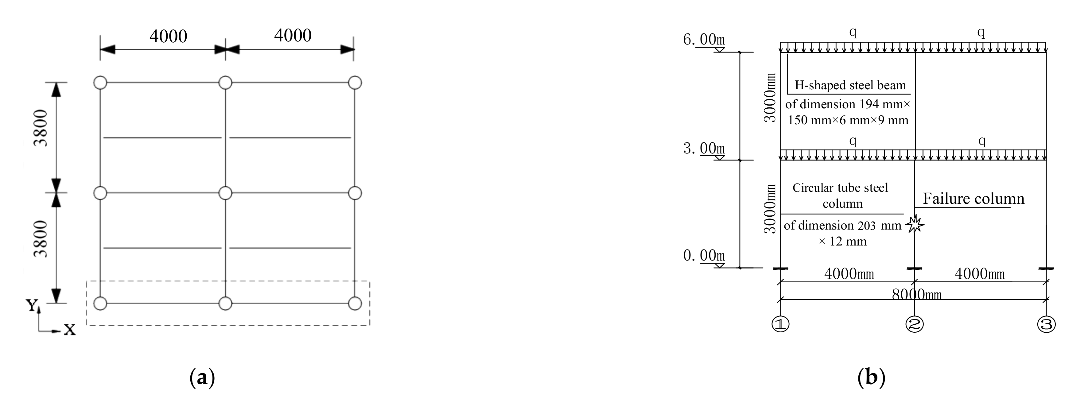
2. Prototype Frame for Progressive Collapse Analysis

In accordance with Chinese design codes [47,48], a prototype two-story steel moment frame was designed to investigate the performance of CSS frames to resist progressive collapse. The plan view and elevation view of this two-story steel frame are shown in Figure 1. In the frame, the dimensions of H-shaped beams are 194 × 150 × 6 × 9 mm, in which the numbers are the depth, flange width, web thickness, and flange thickness of the H-shaped beam, respectively. The circular steel tube column has an outer diameter of 203 mm and a wall thickness of 12 mm. The frame spans in the x and y axes are 4000 mm and 3800 mm, respectively. The height of each floor is 3000 mm.
The prototype two-story frame was designed to have welded joints and CSS joints. G20Mn5 steel was used for the cast steel stiffeners, and HRB235 steel was used for the columns and beams.

3. Detailed Solid-Element Model and the Force Transfer Mechanism of CSS Joint Frame in Progressive Collapse

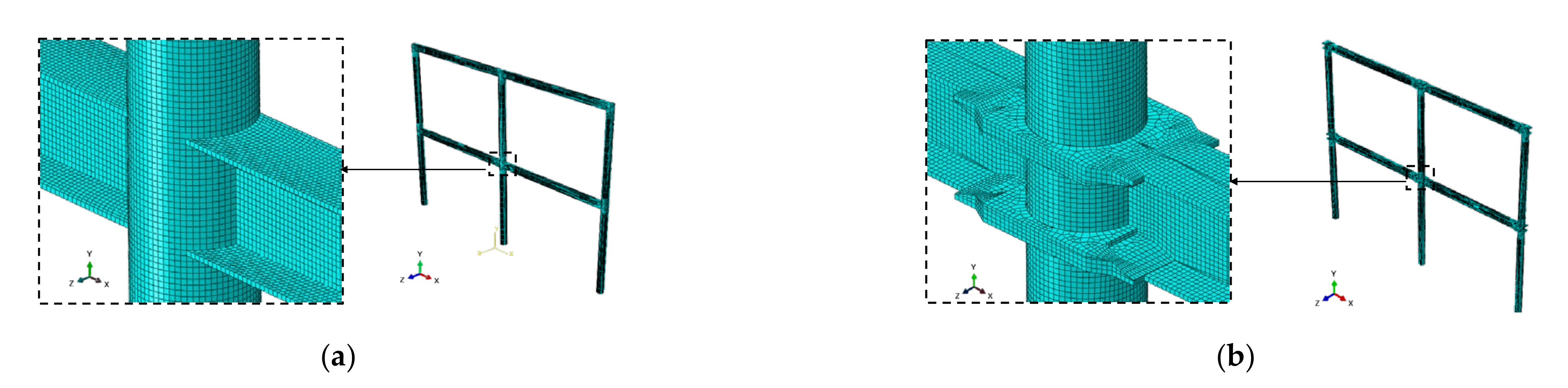
3.1. Detailed Solid-Element Model for Collapse

Detailed solid-element model Ac and model Bc were established by ABAQUS software to simulate the boxed area of the prototype two-story frame in Figure 1a, as shown in Figure 2. Model Ac is a circular-tube-column frame with welded joints, and model Bc is a circular-tube-column frame with CSS joints. These plane frame models are commonly used models for in-depth analysis of structural performance against progressive collapse [1,49].
The dimensions of the CSS for circular tube columns are shown in Figure 3. The CSS consists of a ring plate provided with prefabricated welding grooves, flanges, and stiffening ribs. The reinforcing ribs are rounded to reduce the stress concentration in the CSS.
In model Bc (shown in Figure 2b), the ring plate and the circular tube column are connected by non-penetration butt welds applied along the pre-formed welding grooves. Beam webs are connected to column webs by two-side fillet welds. Moreover, beam flanges are connected to CSS flanges by butt welds. The flat surface of the upper CSS has the same height as the upper surface of the beam flange.
C3D8R elements were used in all the components with an approximate mesh size of 0.01 m (shown in Figure 2); bilinear material models were used for all components and the material parameters of the bilinear models of all components were obtained through material performance tests conducted in reference [38]; all degrees of freedom at column bottoms were constrained before the sudden column removal process. For dynamic alternative load path method (APM) analysis, 1.2 DL + 0.5 LL transformed into mass was applied to the frame according to DOD 2010 [1], where DL and LL are dead load and live load, respectively. The gravity loads were slowly ramped up over a 10 s period. After the 10 s period, the loads have been held constant for an additional 3 s to damp out the dynamic effects. In the next step, the sudden failure of the column was simulated by freeing the vertical support restraint at the interior column bottom within 0.001 s. At last, the simulation continued for 2 more seconds. A 5% mass proportional damping was adopted in this simulation.
The accuracy of this detailed solid-element modeling method has been validated by a test of a CSS joint frame under a sudden interior column removal scenario in reference [50] conducted by the author of this paper. By using this method, a comparison of different detailed solid-element models (i.e., three-dimensional (3D) frame with slabs, 3D frame without slabs, and plane frame) to simulate the test frame in reference [50] is conducted further in this paper, the displacement–time curves of different detailed solid-element models are demonstrated in Figure 4.
Figure 4 shows that the result of the 3D frame with slabs is in good agreement with the test result. The other two models will overestimate the displacement of the interior column in progressive collapse. This displacement result indicates that the out-of-plane pulling actions from orthogonal beams and the rigidity of slabs on the progressive collapse performance of steel moment frames are significant, which helps the structure to resist progressive collapse. Therefore, the plane frame model used in this paper is relatively conservative in comparison to 3D models.

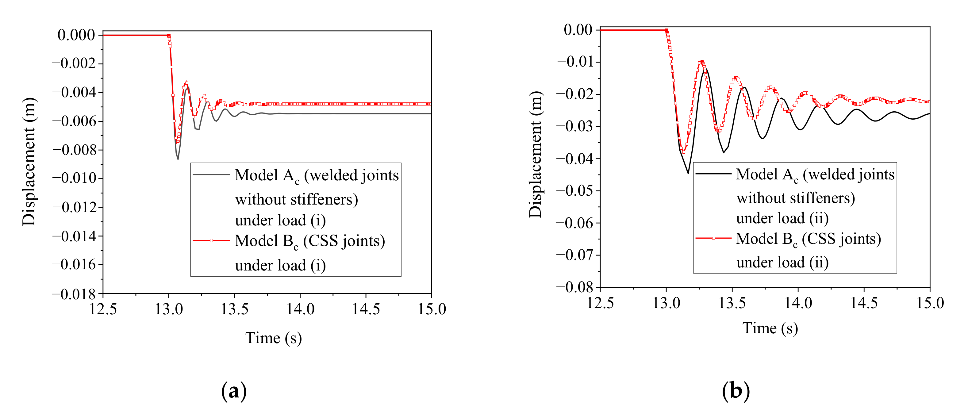
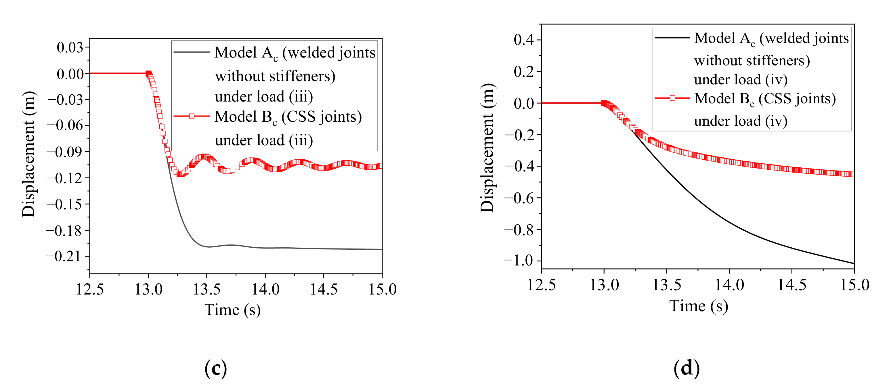
3.2. System Response under Different Load Cases

A series of increasing loads were applied on plane frame models of model Ac and model Bc to simulate the system responses to sudden column loss under different scenarios. To demonstrate and compare the different performances of model Ac and model Bc under the same load, four typical load cases (shown in Table 1) were selected. According to the load code for the design of building structures in China [48], load case (i) represents the load of a light non-accessible slab/roof; load case (ii) represents the load of a normal accessible slab/roof; load case (iii) represents the load of a heavy accessible slab/roof with large live load, such as the load of crowded cabinets in the libraries; and load case (iv) represents the load of a heavy accessible slab/roof with extremely large live load, such as fire vehicle load.
Under the loads in Table 1, displacement–time history curves of the interior column bottoms of model Ac and model Bc are shown in Figure 5, and the maximum and final values of each displacement curve are listed in Table 2. Table 3 lists the time when the plastic strain occurred in model Ac and model Bc under different load levels.
Figure 5, Table 2 and Table 3 show that in the column removal analysis, model Ac and model Bc are elastic under load (i). Under load (i), compared with welded joints, beam-column joints with CSS reduce the maximum and final vertical displacement values of the bottom of the interior column by 13.41% and 12.24%, respectively.
Under load (ii), compared with welded joints, beam-column joints with CSS delay the occurrence of the plastic deformation of structures and reduce the maximum and final vertical displacement values of the bottom of the interior column by 14.77% and 13.94%, respectively.
Under load (iii), these two models undergo plastic deformation at approximately the same time. Compared with welded joints, beam-column joints with CSS reduce the final vertical displacement value of the bottom of the interior column by 47.55%.
Under load (iv), these two models undergo plastic deformation at approximately the same time. The vertical displacements of the interior column bottoms of model Ac and model Bc initially increased rapidly and then increased slowly because of the catenary effect. Compared with welded joints, beam-column joints with CSS reduce the final vertical displacement value of the bottom of the interior column by 55.56%.
In summary, the performance of steel frames with beam-column joints using CSS is better than that of steel frames with welded joints for progressive collapse prevention, whether the frame is elastic, plastic, or collapsed after the sudden failure of the interior column.

3.3. Force Transfer Mechanism

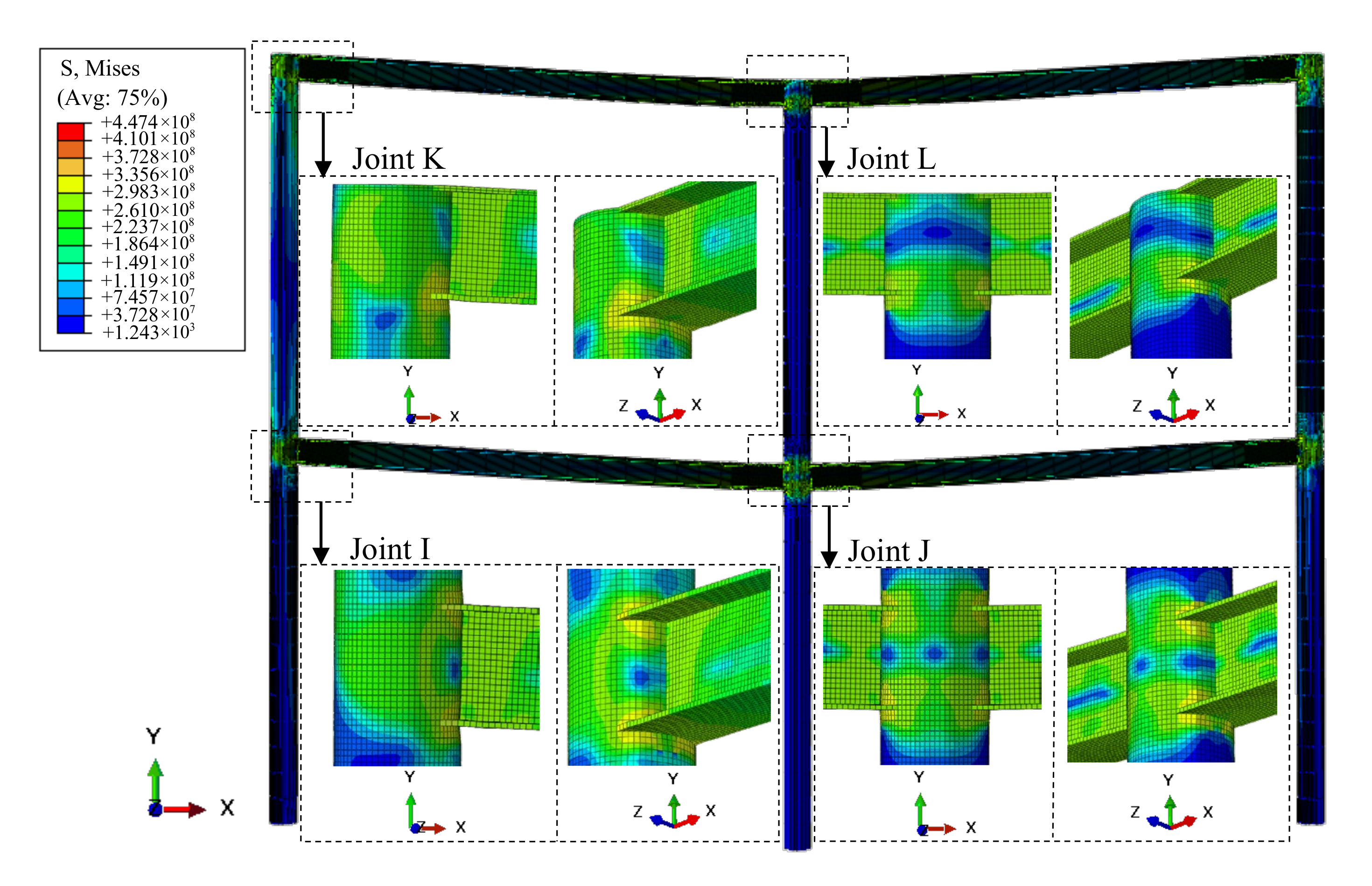
3.3.1. Stress Redistribution
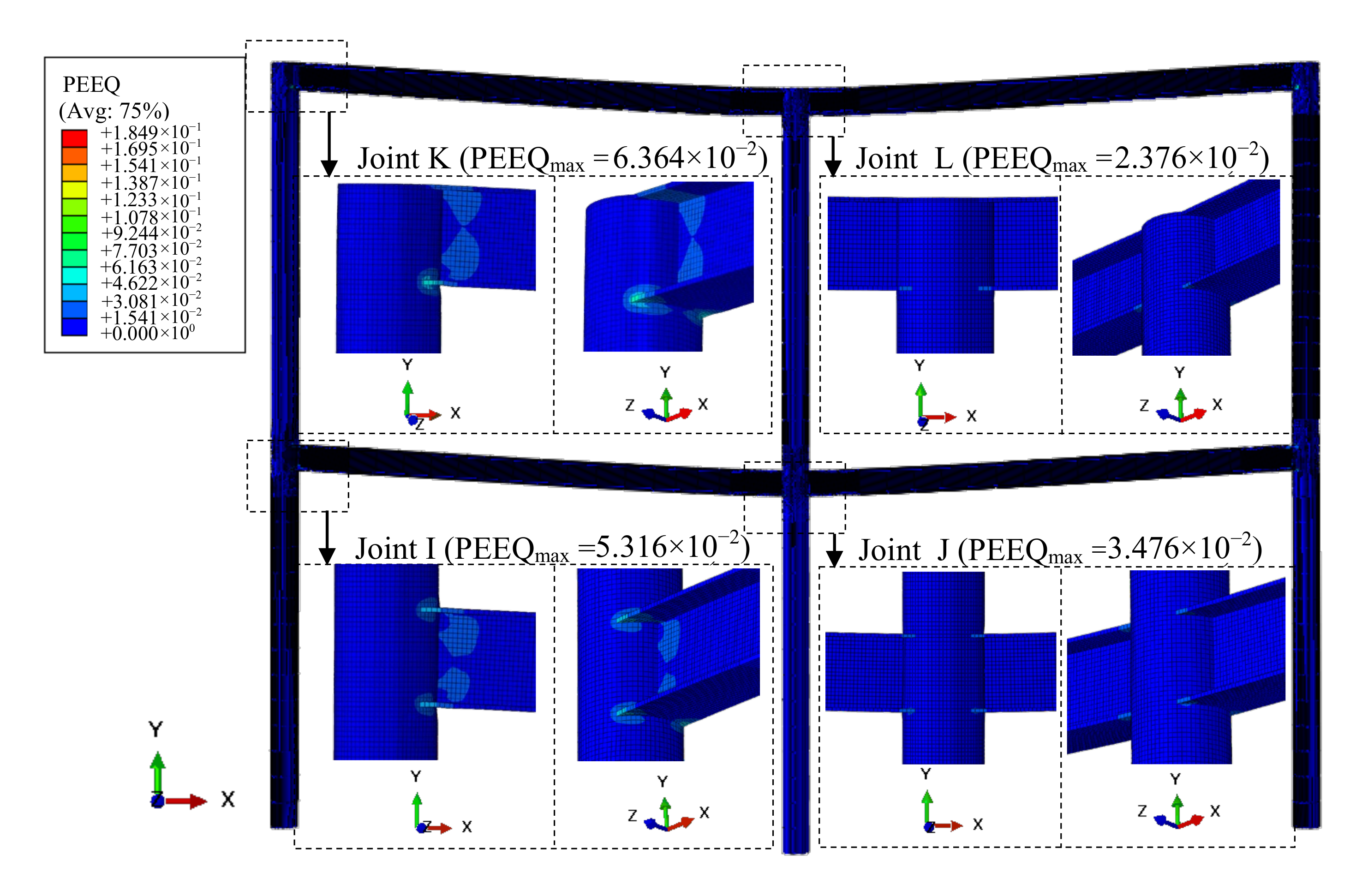
In order to further illustrate the differences in equivalent plastic strain redistribution and stress redistribution between steel frames with welded joints and CSS joints, models Ac and Bc under load (iii) were demonstrated as examples.
The corresponding equivalent plastic strain redistribution and stress redistribution of model Ac at 15 s are shown in Figure 6 and Figure 7, respectively. Figure 6 and Figure 7 show that the stress concentration region is located at the corner where the flange of the beam end and the column are connected. Due to the tensile force of the beam flange, the column bears a large axial force, which results in an obvious buckling. The maximum equivalent plastic strain of model Ac is 0.0636. The deformation of the joints and beam ends of the frame presents a “V”-shaped curve after the sudden failure of the interior column.
The corresponding equivalent plastic strain redistribution and stress redistribution of model Bc when the maximum displacement occurred are shown in Figure 8 and Figure 9, respectively. The result shows that the stress concentration region occurs mainly at the CSS. This is due to the fact that the CSS has relatively high strength and rigidity and bears a large portion of the tension load transmitted from the beam end, so the tension load borne by the column front shell is reduced, avoiding large strains in the column front shell. The maximum equivalent plastic strain of model Bc is 0.0232, and the obvious deformation is mainly concentrated at the beam end rather than the column. Due to the large rigidity of the beam-column joint with CSS, which restricts the joint deformation, the deformation of the frame presents a relatively smooth “U”-shaped curve after the sudden failure of the interior column.

3.3.2. Failure Mode

To illustrate the different failure modes of model Ac and model Bc in progressive collapse, the time history curves of the maximum equivalent plastic strains at the buckled regions and the interior column displacements of the two frames under load (iv) are presented in Figure 10. In Figure 10a, significant local buckling develops with the increase of the interior column displacement; in Figure 10b, only slight local buckling develops after the sudden column removal. The different failure modes of these two models result in a larger increase in displacement for model Ac than for model Bc.

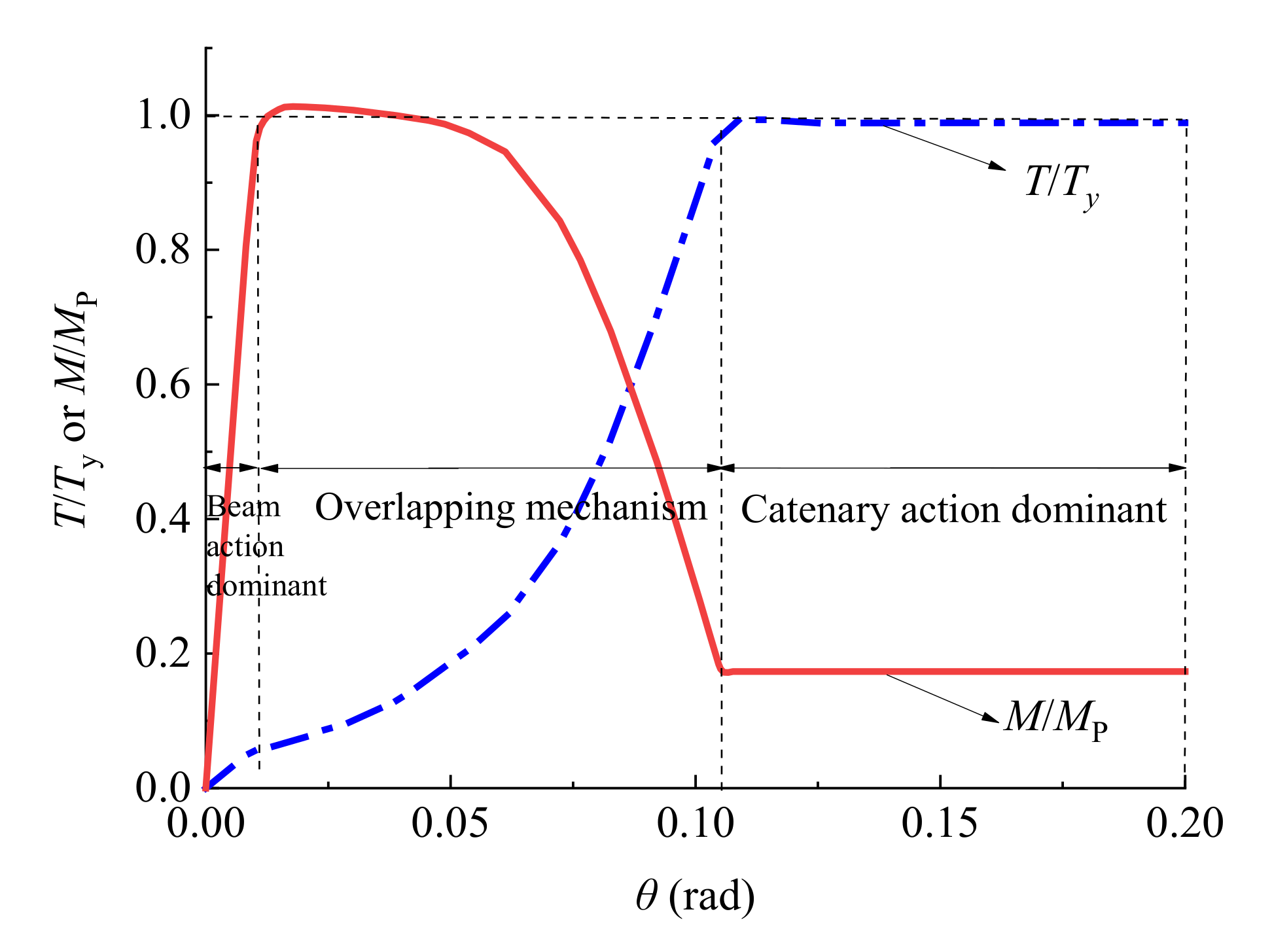
3.3.3. Axial Tension–Bending Moment Interaction at Beam Ends

Figure 10b shows that the final damage of model Bc is caused by the plastic hinge occurring at the beam ends connected to the outer side of the CSS flange. In order to study the axial force–bending moment interaction at beam ends, model S (shown in Figure 11a), a subassembly two-span frame, was extracted from model Bc. A vertical loading method was applied to the top section of the interior column with a load rate of 2 mm/min until the final vertical downward displacement reached 2 m. The rotations and displacements of the bottom and top sections of the corner columns were restricted. The column was set as a rigid body to prevent joint damage from occurring earlier than the damage to the beam. Figure 11b shows the distribution of the equivalent plastic strain for model S.
In Figure 11b, plastic hinges develop at both ends of the beams. The axial tension (T) and bending moment (M) at beam ends are normalized by the plastic bending moment (Mp) and the tensile yield strength (Ty) of the beam, respectively. The (T/Ty) and (M/Mp) on the ordinate axis are shown in Figure 12. In Figure 12, steel beams are gradually transformed from bending members into tension–bending members with the increase of the column displacement. Finally, the subassembly frame relies on the internal axial tension of the beams to resist progressive collapse. This is a typical catenary effect process [51].
To sum up, the greater overall stiffness and strength of the CSS limit the deformation of the column front shell, which results in a very different stress redistribution and deformation pattern in CSS joints compared with welded joints. In the CSS joint frame, plastic hinges at beam ends appear at locations farther away from columns, thus changing the deformation pattern of the whole frame after the sudden failure of the interior column. Moreover, the bending moment–axial tension interaction relationship of the plastic hinge region indicates that the frame still exhibits the catenary effect even if the plastic hinge region is moved outward.

4. Component-Based Model for Frames with Circular Tube Columns and CSS Joints

In practice, detailed solid-element models are time-consuming and complicated, even for the detailed solid-element model of a plane frame. Therefore, establishing a practical and efficient component-based model that fully considers the force transfer mechanism and the special construction of the CSS joint for progressive collapse analysis is necessary.
In the circular-tube-column joint, the load (M) applied to the joint is mainly born by the CSS due to its large stiffness, and only negligible load is borne by the web. Therefore, the load (M) can be simplified as hb multiplied by F, where hb is the distance between the centers of the lower and upper flanges of the beam and F is the compression/tension force on the CSS (shown in Figure 13).
Based on this simplified principle, the component-based model can be constructed. First, four rigid rods should be hinged together to simulate the panel zone of the column to meet the corresponding deformation requirements; a diagonal spring should be used to connect two diagonal points of the panel zone to simulate its deformation; and a rotation spring should exist to represent the deformation of the CSS ring and column front shell. Second, a plastic deformation region with rotational springs and tension–compression springs should exist to represent the shearing and bending resistance of the beam end. Third, a rigid member should be arranged between the panel zone and the plastic deformation region of the beam to represent the relatively high rigidity of the CSS fringe. In addition, other regions of the beams and columns in the frames can be simulated by beam elements. Based on this analysis, the frame studied in Section 3 can be simplified to a component-based model shown in Figure 14.

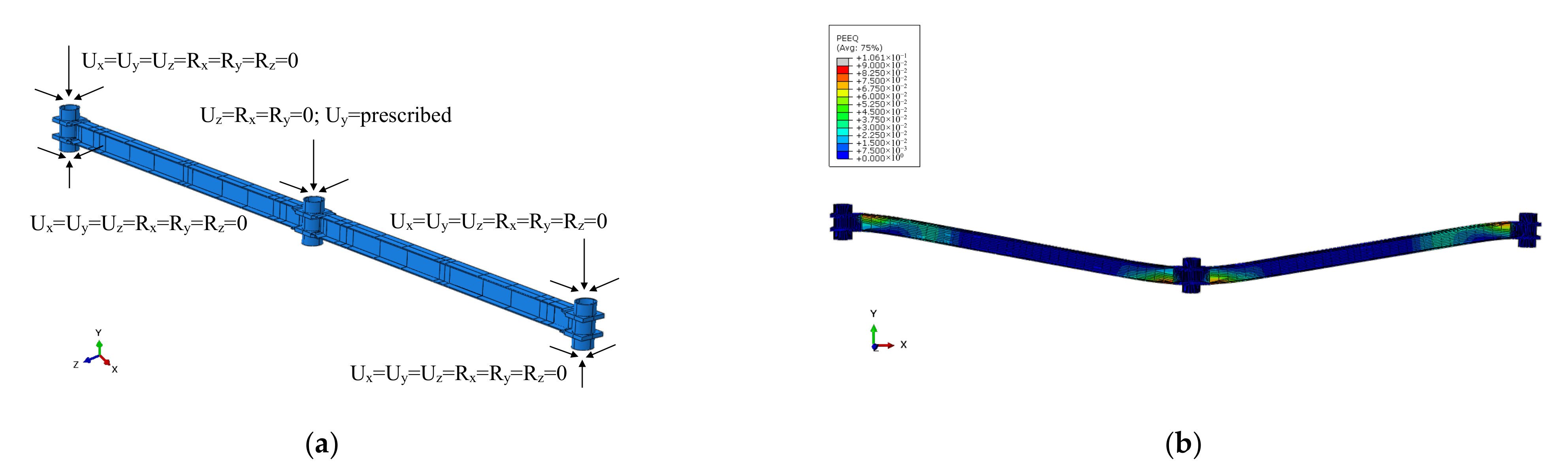
4.1. Plastic Deformation Region Properties at Beam End

In order to consider the catenary effect, the plastic deformation region of a beam in the component-based model is combined with a plastic hinge model with a tension–bending spring [40], which was proposed by Lee et al. The model assumes that the column and the joint section are rigid, so all inelastic deformations occur at beam ends. The applicability of this model to simulate the catenary effect of any H-shaped beam without considering the details of the joints was validated in reference [40].

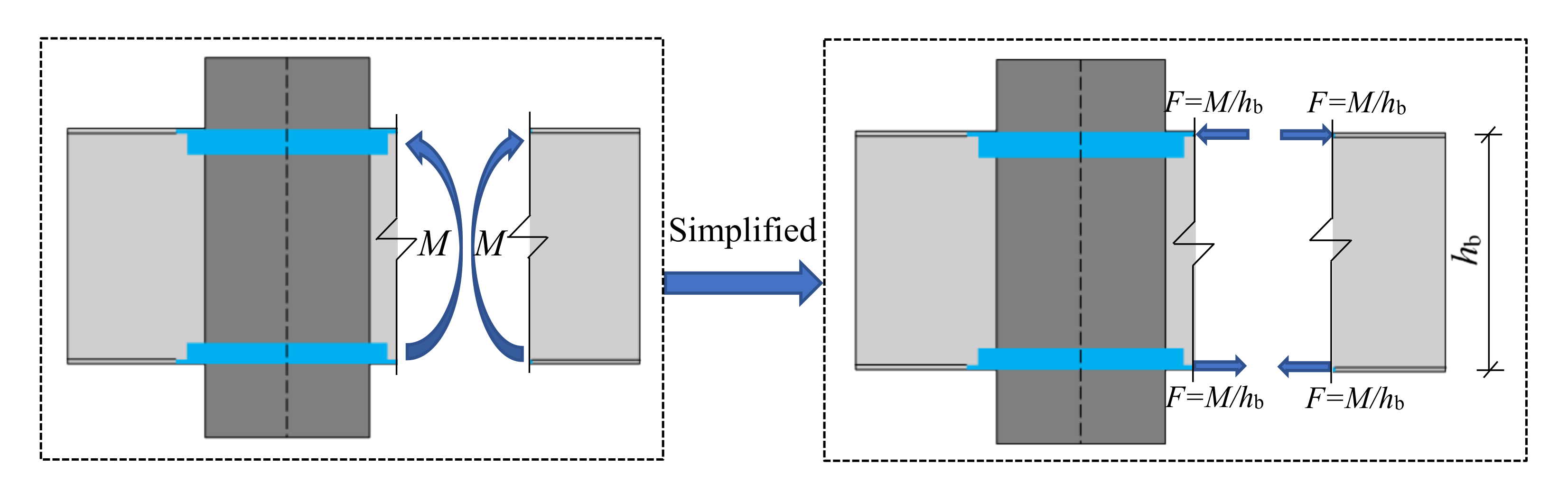
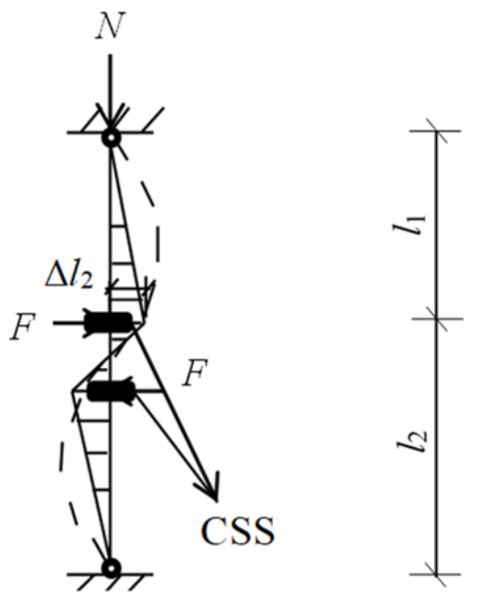
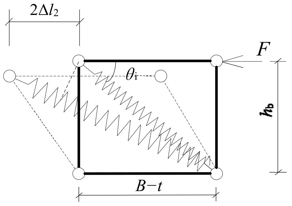
4.2. Force–Displacement Interaction Relationship of Joint Springs

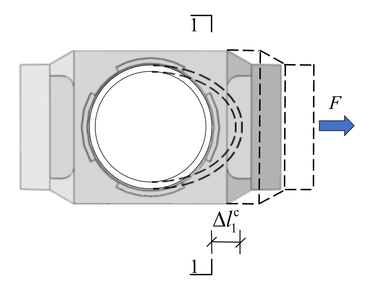
4.2.1. Initial Stiffness of Joint Springs

  • Rotational spring
The relative deformation of the lower and upper CSS on one side of the joint will cause the section to rotate, which can be simulated by a rotational spring. The initial rotational stiffness of the spring simulating the deformation of CSS can be deduced as detailed below.
The displacement of the CSS ( Δ l 1 c ) is shown schematically in Figure 15. The experimental and numerical analyses in reference [38] revealed that for the H-shaped beam to circular-tube-column joints with CSS, the external tension/compression force on the CSS is borne by the CSS and the column front shell, and the deformations of them are coordinated, so the load can be distributed according to the tensile stiffness ratio of the ring plate of CSS to the column front shell. According to the analysis and deduction from the literature [38], the relationship between the force Fs distributed to the CSS and the total force F is expressed as
F s = F 1 + L s 2 E s A s D X c L L 1
X c = m = 1 , 3 , 5 n = 1 , 3 , 5 4 [ ( m π L ) 2 + ( n π L 1 ) 2 ] 2 sin 2 m π 2 sin 2 n π 2 ( L L 1 ) 2 [ ( m π L ) 2 + ( n π L 1 ) 2 ] 4 + E c t R 2 D ( m π ) 4 ( L 1 L ) 2
where Es is the elastic modulus of the CSS; and Ls/As is the ratio of the length to the cross-sectional area of the ring plate of the CSS in the force direction. Due to the complex shape of the CSS for the circular-tube-column joint, it needs to be calculated by integration; D is the unit bending stiffness of the cylindrical front shell of the circular tube column; Xc is a dimensionless parameter; L is the bus length of the cylindrical front shell; L1 is the arc length of the cylindrical front shell; R is the radius of the middle surface of the cylindrical front shell; t is the thickness of the cylindrical front shell; and Ec is the elastic modulus of the column.
Based on Equation (2), the displacement of the CSS ( Δ l 1 c ) is given as
Δ l 1 c = F s E s A s L s = F 1 + L s 2 E s A s D X c L L 1 L s E s A s
Based on Equation (3), the calculation equation for the initial rotational stiffness of the joint rotation spring ( k s c ) is given as:
k s c = M θ CSS = F h b 2 Δ l 1 c h b = h b 2 E s A s 2 L s + h b 2 D 4 X c L L 1
where M is the bending moment on one side of the joint; θCSS is the rotation angle on one side of the joint; and hb is the distance between the centers of the lower and upper flanges of the H-shaped beam.
b.
Panel zone spring
In order to obtain the deformation of the panel zone spring, the horizontal displacement of the column at the position of the CSS (Δl2) should be analyzed first. Δl2 is shown in Figure 16. The displacement of the column at the position of CSS is composed of two parts, namely, the deformations caused by the bending moment and shearing force of the steel tube column. Therefore, the deformation Δl2 is given as
Δ l 2 = F h b 2 l 1 3 + ( l 2 h b ) 3 6 E c I c ( l 1 + l 2 ) ( l 1 + l 2 h b ) + F k c h b ( l 1 + l 2 h b ) 2 G c A c ( l 1 + l 2 )
where Ac is the cross-sectional area of the column; kc is the shear correction coefficient; Gc is the shear modulus; Ic is the inertia moment of the column section; l1 is the distance from the midpoint of the upper layer to the center of the upper beam flange; and l2 is the distance from the midpoint of the layer in which the beam is included (if this layer is the ground layer, then to one-third of the height of this layer) to the center of the upper beam flange.
The deformation schematic diagram of the panel zone spring is shown in Figure 17, where θi is the interior angle of the horizontal rigid member to the diagonal panel zone spring, which is given as
1 cos 2 θ i = ( B t ) 2 + h b 2 ( B t ) 2
Then, the calculation equation of the initial rotational stiffness of the spring simulating the deformation of the panel zone ( k pz s ) is given as
k pz s = F 2 Δ l 2 × 1 cos 2 θ i = 1 h b 2 ( l 1 3 + ( l 2 h b ) 3 ) 3 E c I c ( l 1 + l 2 ) ( l 1 + l 2 h b ) + k c h b ( l 1 + l 2 h b ) G c A c ( l 1 + l 2 ) × 1 cos 2 θ i
In order to validate the applicability of the joint springs in the component-based model, the joint test results of the specimens with column thicknesses of 8 mm, 10 mm, and 12 mm in the literature [38] are taken as examples. The specimens are cross joints with circular tube columns, H-shaped beams, and CSS joints. The detailed solid-element model and the component-based model established in this paper for simulating these specimens are shown in Figure 18a,b, respectively. The initial rotational stiffness of test specimens, the detailed solid-element models, and the component-based models are listed in Table 4.
In Table 4, the initial rotational stiffness results of the test specimens, detailed solid-element models, and the component-based models are consistent with each other, which proves the applicability of the joint springs in the component-based model to simulate the H-shaped beam to circular-tube-column joints with CSS.
Based on the validation above, parameterized analysis of the initial rotational stiffness obtained from the component-based model was further conducted by varying the parameters in Equations (1)–(7). Compared with the numerical simulation results of the detailed solid-element models, the parameterized results are listed in Table 5. The results indicate that the initial rotational stiffness results of detailed solid-element models are consistent with those of the component-based models, which further verifies the applicability of the component-based model for the H-shaped beam to circular-tube-column joint with CSS.

4.2.2. The Stiffness of the Joint Springs after Yielding

(1)
Bearing capacity
a.
Rotational spring
According to reference [38], the calculation equation of the resultant tensile bearing capacity of the CSS and the column front shell ( F p c ) is given as:
F p c = f y , css A s , min + f y , c t 2 l w X p + 2 ( X p + h s ) f y , c t 1 + 2 cos 2 θ c
X p = l w t ( 1 + 2 cos 2 θ c ) 2
where fy,css is the yield strength of the CSS; As,min is the minimum cross-sectional area of the CSS perpendicular to the force direction; fy,c is the yield strength of the column; lw is the weld length; θc is half of the central angle corresponding to the arc length of the weld; and hs is the height of the CSS.
The calculation equation for the bending bearing capacity M p , s c of the joint rotational spring is given as
M p , s c = ( f y , css A s , min + f y , c t 2 l w X p + 2 ( X p + h s ) f y , c t 1 + 2 cos 2 θ c ) h b
Combined with Equation (4), the rotation angle θ p , s c corresponding to the bending bearing capacity M p , s c can be calculated as:
θ p , s c = M p , s c k s c = f y , css A s , min + f y , c t 2 l w X p + 2 ( X p + h s ) f y , c t 1 + 2 cos 2 θ c h b E s A s 2 l s + h b D 4 X c L L 1
b.
Panel zone spring
According to the Eurocode 3 [52] about the shear capacity of panel zones (Vp,pz), the tensile bearing capacity of the spring simulating the deformation of the panel zone ( F p , pz s ) can be deduced as
F p , pz s = V p , pz cos θ i = f v , pz A v cos θ i
where fv,pz is the shear strength of the panel zone; and Av is the shear area of the panel zone. For the circular tube column, the shear area of the panel zone (Av) can be deduced as
A v = 2 A c / π
where Ac is the cross-sectional area of the steel tube column when the thickness of the column is uniform.
Combined with Equation (7), the deformation Δ l p , pz s corresponding to the tensile bearing capacity F p , pz s can be calculated as:
Δ l p , pz s = F p , pz s k pz s = 2 f v , pz A c cos θ i π × ( h b 2 ( l 1 3 + ( l 2 h b ) 3 ) 3 E c I c ( l 1 + l 2 ) ( l 1 + l 2 h b ) + k c h b ( l 1 + l 2 h b ) G c A c ( l 1 + l 2 ) )
(2)
Post-yield stiffness
Based on the test results of the specimens in reference [38], the post-yield stiffness is only 0.090 to 0.103 of the initial stiffness of the CSS joint. Therefore, the post-yield stiffness of the joint springs in the component-based model can be safely defined as zero, which means the simulation of the component-based model for CSS frames in progressive collapse is conservative.

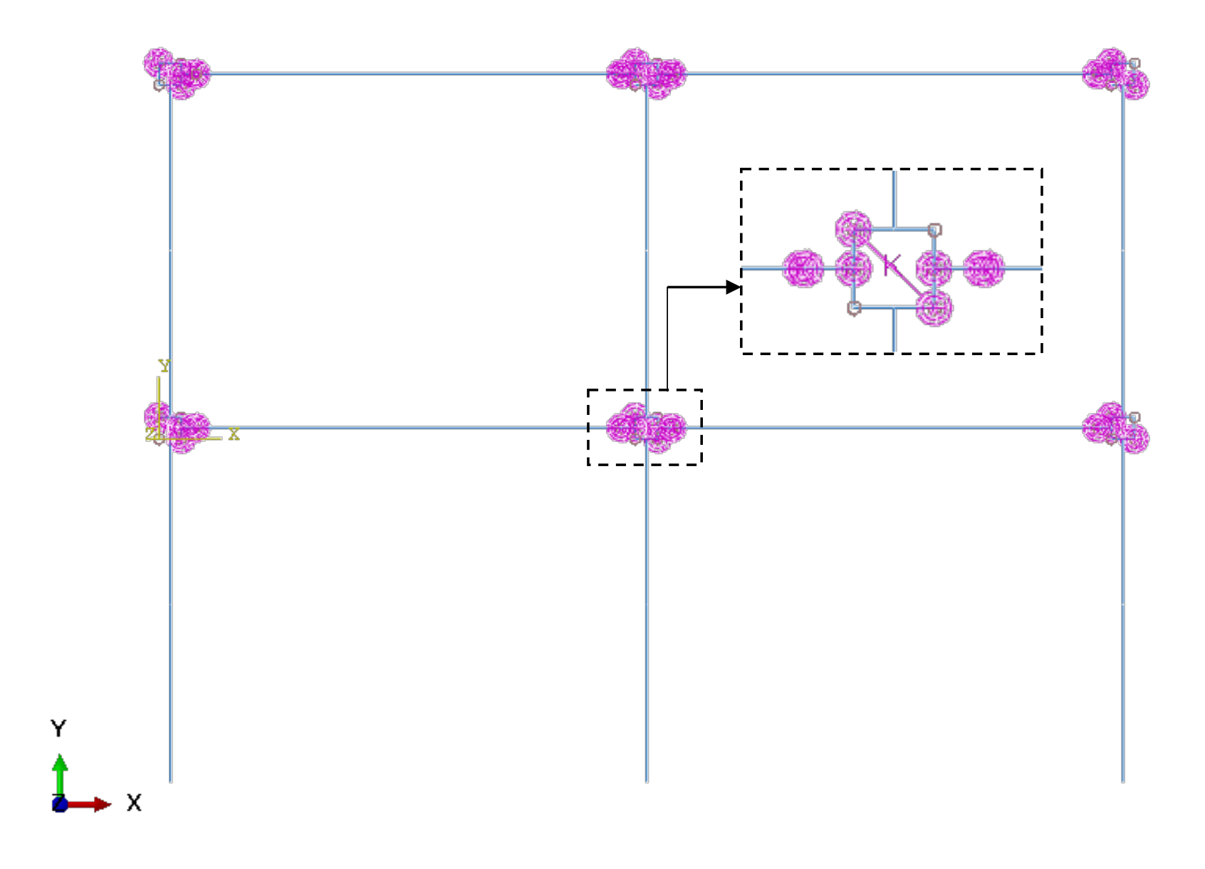
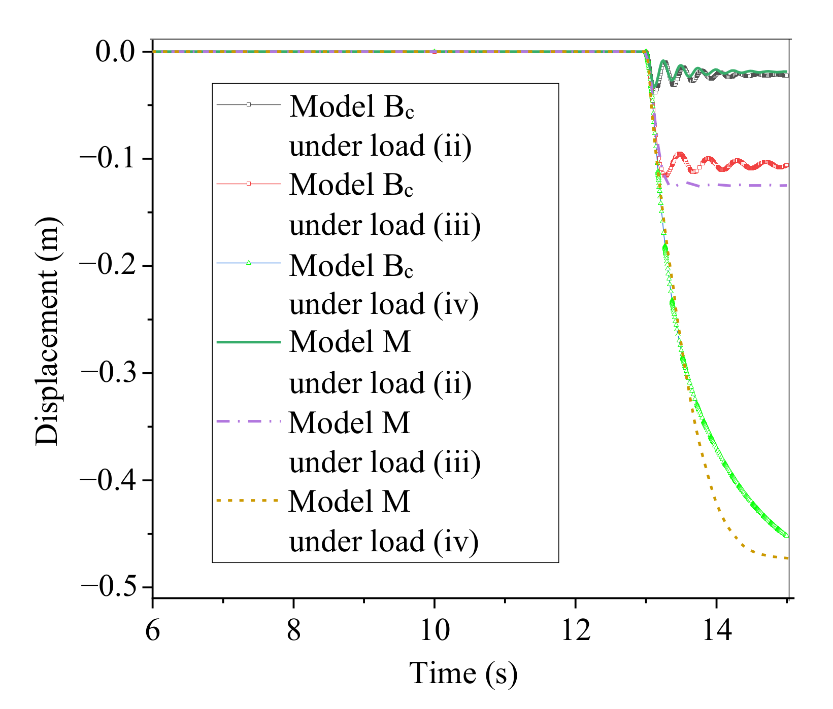
4.3. Component-Based Model Response under a Sudden Column Removal Scenario

To validate the applicability of the component-based model for the frames with CSS joints in the dynamic nonlinear analysis under a column removal scenario, the detailed solid-element model of the CSS joint frame in Section 3 was remodeled by the component-based model method (shown in Figure 19). Under various loads in Table 1, the vertical displacements of the bottoms of the interior columns in the component-based model and the detailed solid-element model were compared. The comparison results are shown in Figure 20.
Figure 20 shows that in the dynamic nonlinear numerical analysis, the results of the component-based model are consistent with those of the detailed solid-element model, which proves the applicability of the component-based model in the dynamic nonlinear column removal analysis.

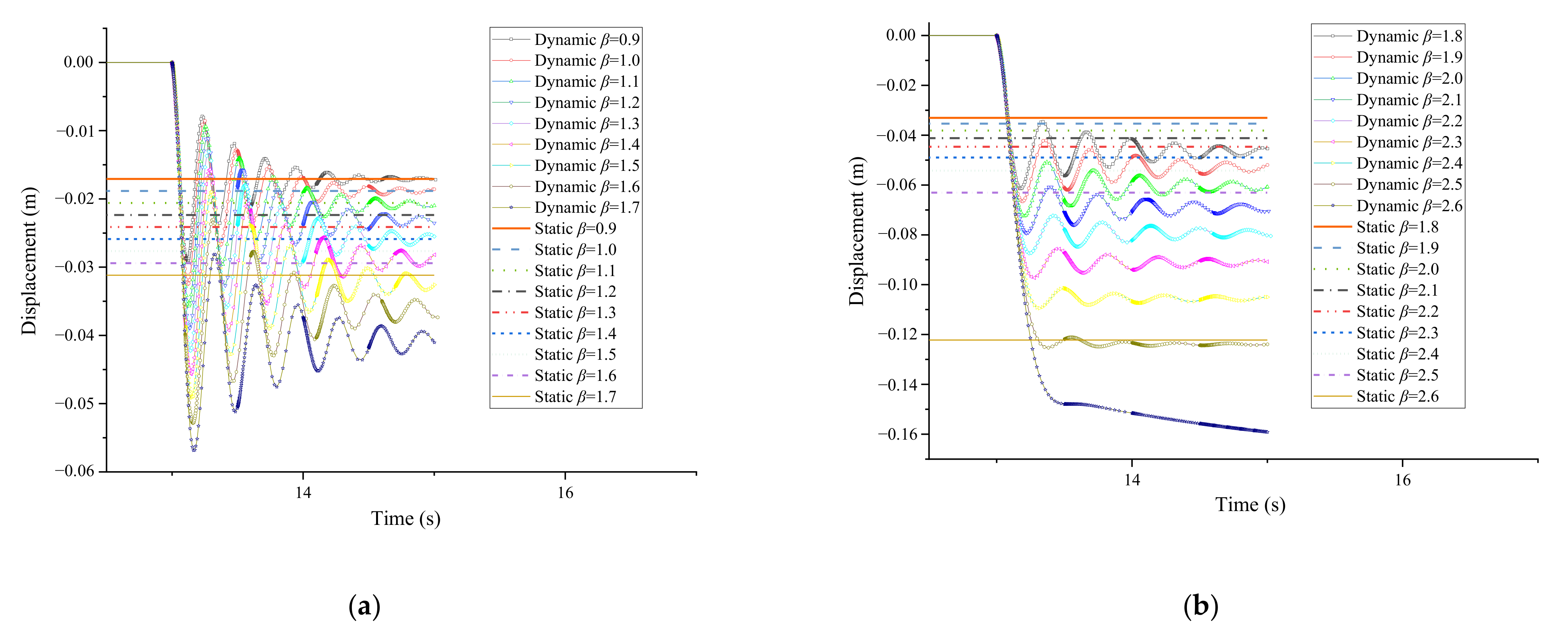
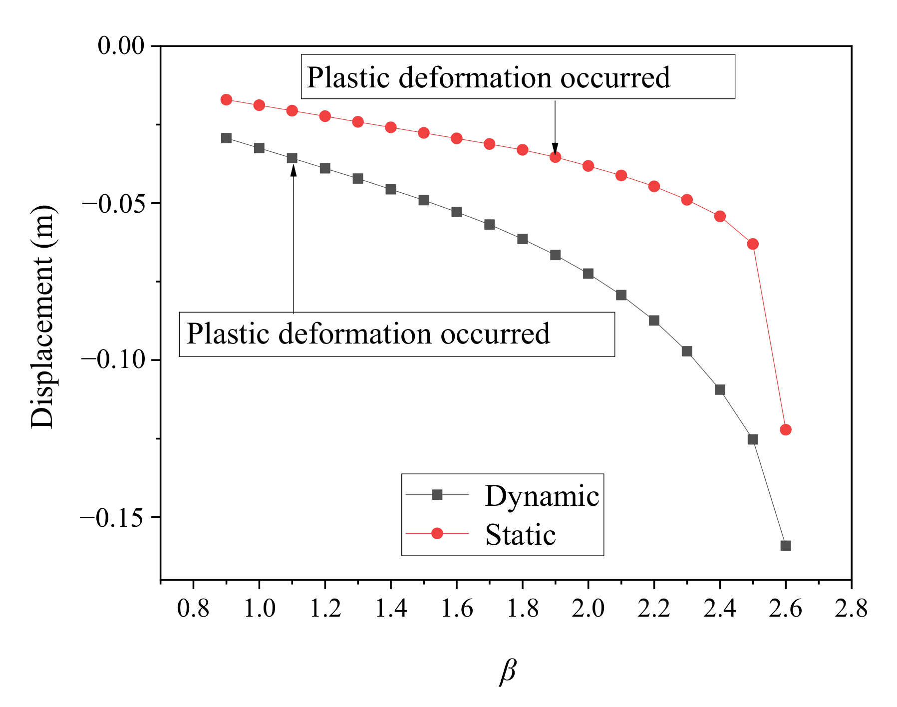
5. Dynamic Response Increase Factor

To further simplify the analysis process of CSS joint frames for progressive collapse prevention, the dynamic response of the structure can be equivalently analyzed by a static analysis method based on the recommendations in the DoD2010 guidelines [1]. Specifically, when the structure is designed to resist progressive collapse, the alternative load path method combined with a load combination of 1.2 DL + 0.5 LL can be used for dynamic analysis, while ΩDIF (1.2 DL + 0.5 LL) can be used for static analysis. ΩDIF is the dynamic increase factor (DIF) used in the nonlinear static analysis to consider the dynamic effect, DL is dead load, and LL is live load. The ΩDIF of steel structures can be defined by the formula ΩDIF = 1.08 + 0.76/(θpra/θy + 0.83), where θpra/θy is the ratio of the allowable plastic rotation θpra to the yield rotation θy. Generally, ΩDIF can be conservatively selected as 2.0.
The formula proposed by the DoD 2010 [1] provides a usable method for calculating ΩDIF, but the effect of the joint type is not taken into account in the formula. In order to obtain the ΩDIF applicable to the CSS joint frames, the component-based model established in this paper can be used for efficient computation.
Under different levels of load, a series of nonlinear static and dynamic analyses were carried out using the component-based model. The ratio of the ultimate load of the static analysis to the ultimate load of the dynamic analysis is the dynamic response increase factor. For the convenience of description, different magnitudes of load can be represented by β (1.2 DL + 0.5 LL), where DL and LL are the dead load and the live load of the structure, respectively, and different load levels are obtained by varying β from 0.9 to the value corresponding to the case when the interior column displacement begins to increase.
Taking DL = 3.2 kN·m−2 and LL = 2 kN·m−2 as examples, the vertical displacements of the interior column in static and dynamic analyses under the gradually increasing load are shown in Figure 21. The relationships between the maximum vertical displacement and β in the dynamic and static analyses of the circular-tube-column frame are shown in Figure 22. Note that the β (1.2 DL + 0.5 LL) is a representation of the total load. If other loading cases with different live and dead loads are chosen, the same outcomes of the ultimate resistance load of static analysis and dynamic analysis of this frame can be obtained with the increase of β, and then the same dynamic increase factor of this component-based model can be obtained.
The calculation results show that for the circular-tube-column frame with CSS joints, when β ≤ 1, the frame is elastic. In dynamic analysis, when β = 1.1, plastic deformation occurs; when β = 2.6, the vertical displacement of the bottom of the interior column increases rapidly at first, then slowly, and the displacement reaches 159 mm at 15 s. In the static analysis, when β = 1.9, plastic deformation occurs; when β = 2.6, the displacement of the interior column is merely 122 mm. Before the plastic deformation of the frame occurred, the ultimate load of static analysis is 1.9 (1.2 DL + 0.5 LL) and the ultimate load of dynamic analysis is 1.1 (1.2 DL + 0.5 LL). Therefore, the dynamic response increase factor (ΩDIF) of 1.7, which is the ratio of 1.9 (1.2 DL + 0.5 LL) to 1.1 (1.2 DL + 0.5 LL), is suitable for a CSS joint frame with circular tube columns. This ΩDIF is smaller than the 2.0 recommended in DoD 2010 [1] because the CSS joints reduce the maximum deformation of the frame during the progressive collapse.

6. Conclusions

In this paper, the force transfer mechanism of cast steel stiffener (CSS) frames under a column removal scenario was revealed by detailed solid-element models. Based on the mechanism analysis and the simplification principle that conforms to the frame characteristics, a practical component-based model suitable for the progressive collapse analysis of CSS frames was established and validated, and then the dynamic response increase factor for circular-tube-column frames with CSS joints was investigated by using this component-based model. The main conclusions are as follows:
(1)
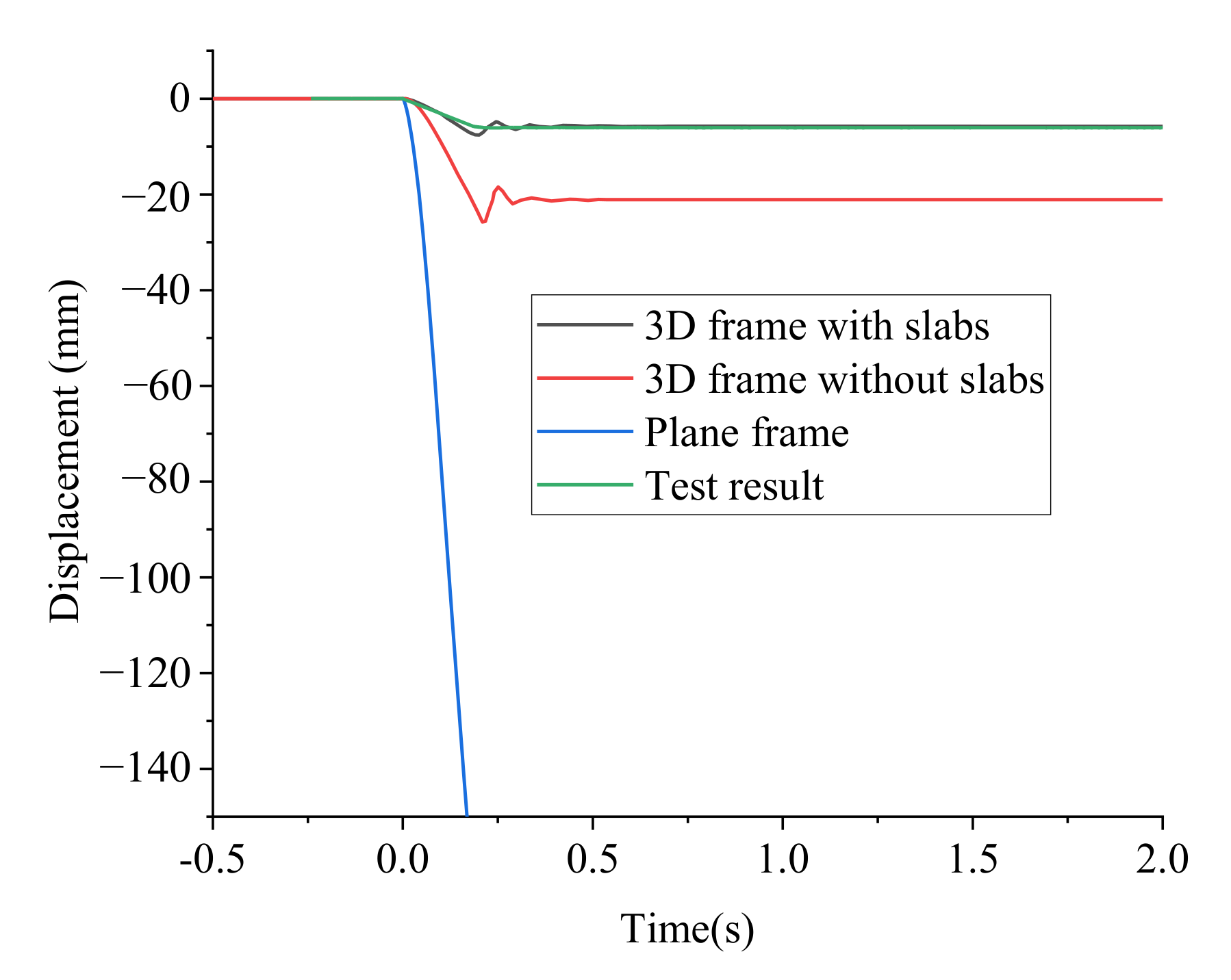
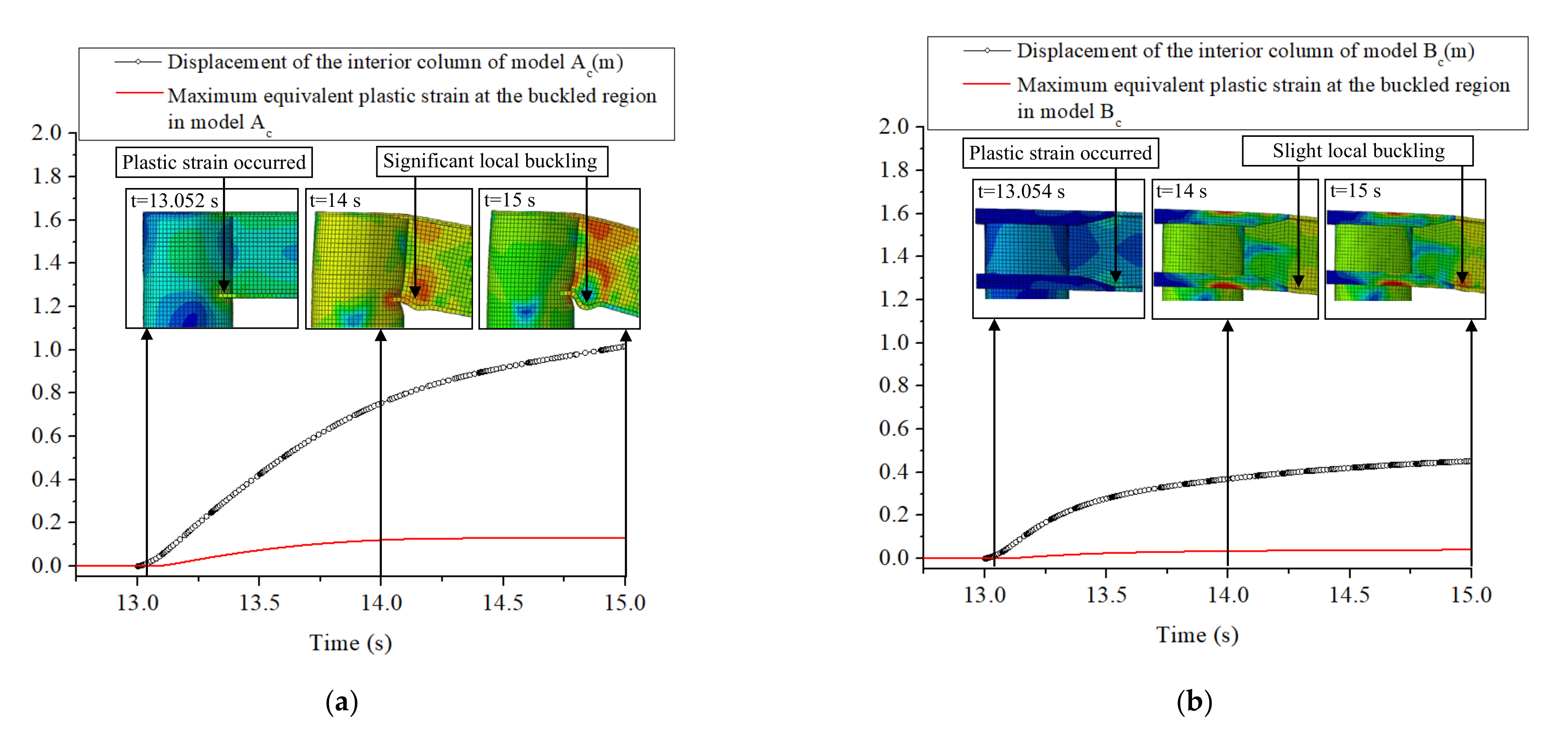
The performance of the CSS joint frame for progressive collapse prevention is better than that of the fully welded joint frame. The CSS can delay the occurrence of plastic deformation of the CSS structures; the maximum and final values of the vertical displacement of the interior column in the CSS joint frame can be reduced, whether the frame is elastic, plastic, or collapsed after the sudden failure of the interior column.
(2)
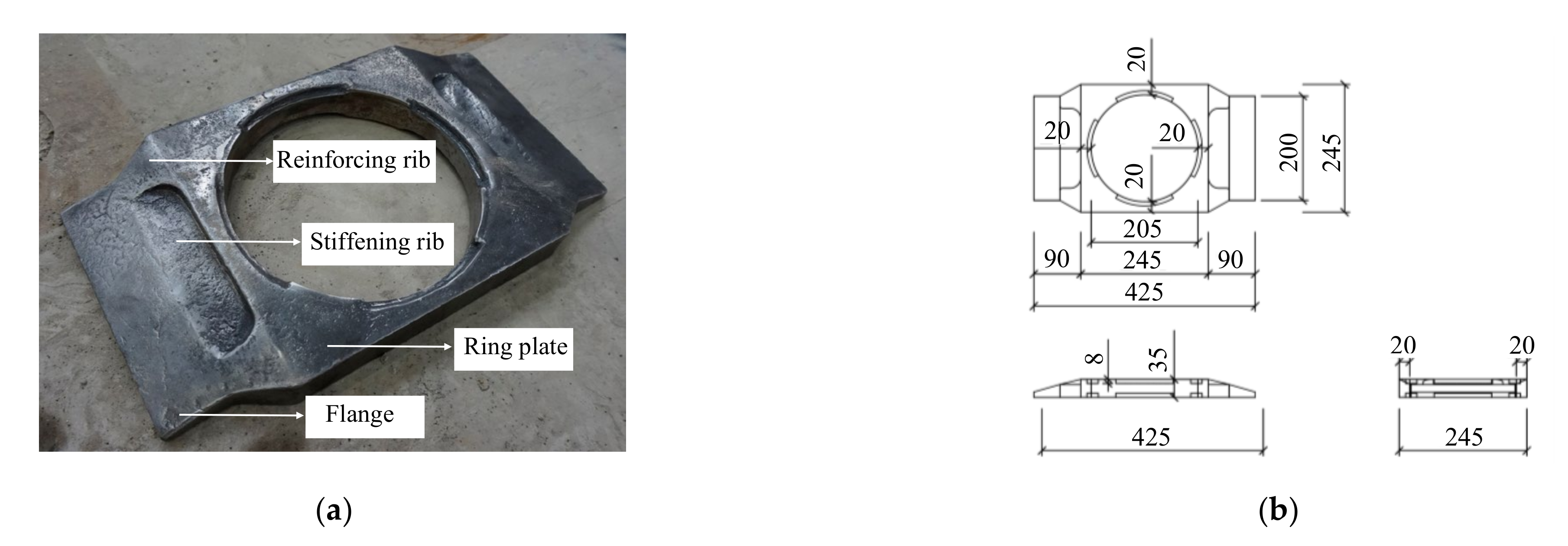
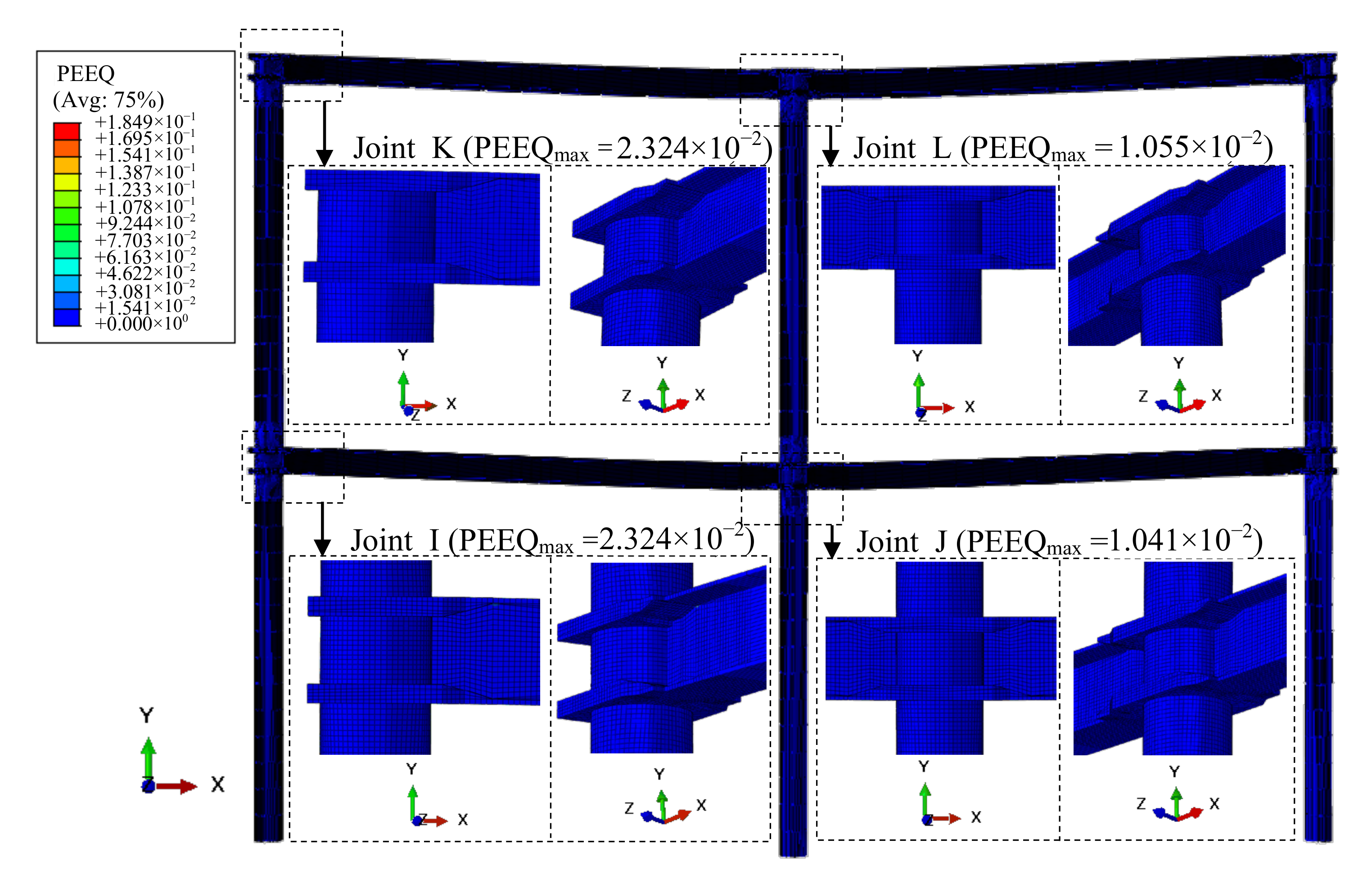
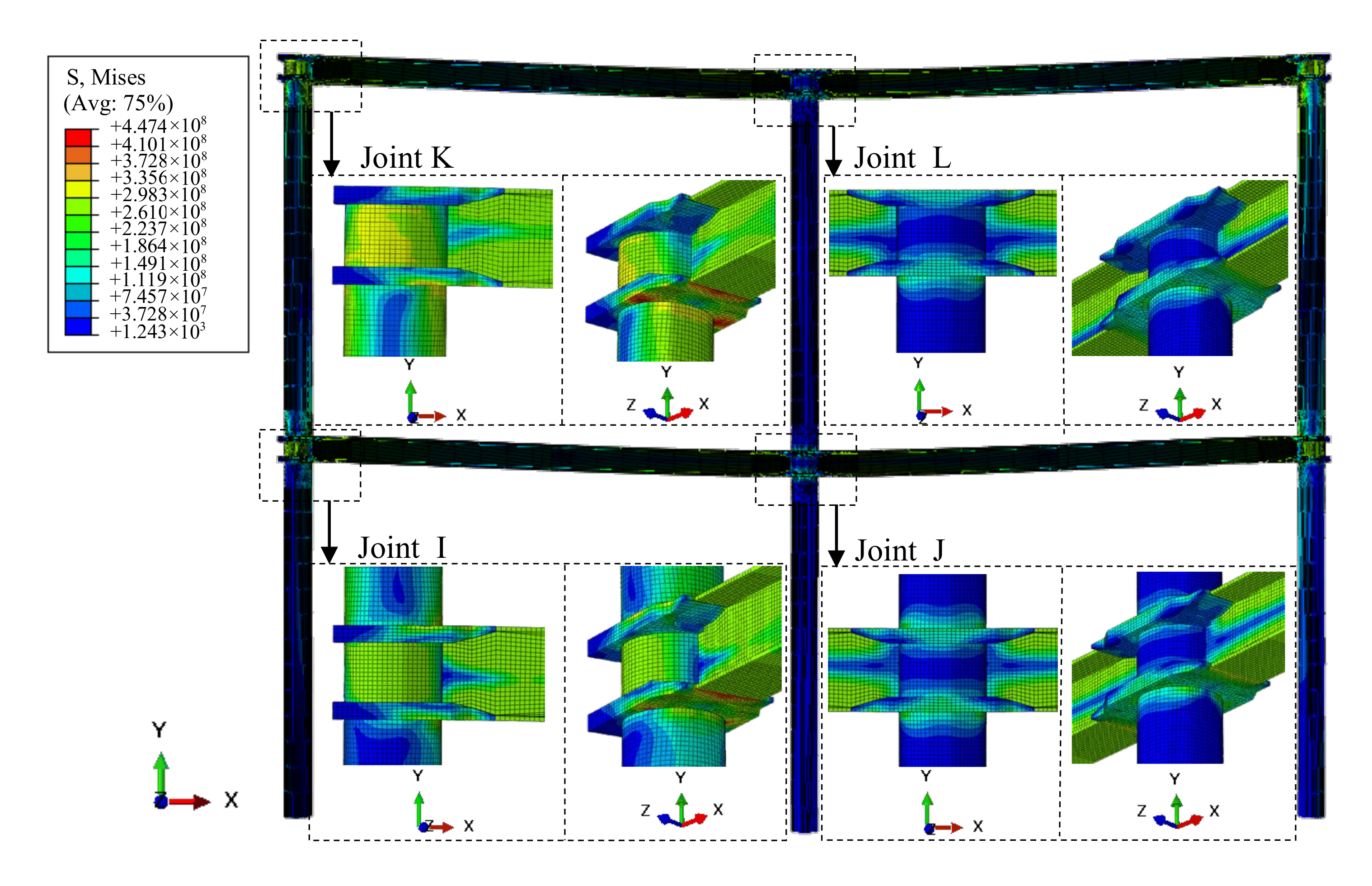
In the case of sudden column removal, the stress distribution and the deformation mode of the CSS frame are revealed. Due to the relatively high rigidity and strength, the CSS can effectively bear the tensile loads from the flanges at beam ends and reduce the tensile loads borne by the front shell of the column, so the large strain of the column front shell is avoided. At the same time, due to the large strength and thickness of the cast steel stiffeners, the strain of the cast steel stiffeners is small. Therefore, the overall strain of the CSS joint is small and the stress distribution is relatively uniform. Moreover, plastic hinges at beam ends appear at locations farther away from columns in CSS joint frames, so the joints and the beam ends present relatively smooth-shaped curves after the sudden failure of the interior column.
(3)
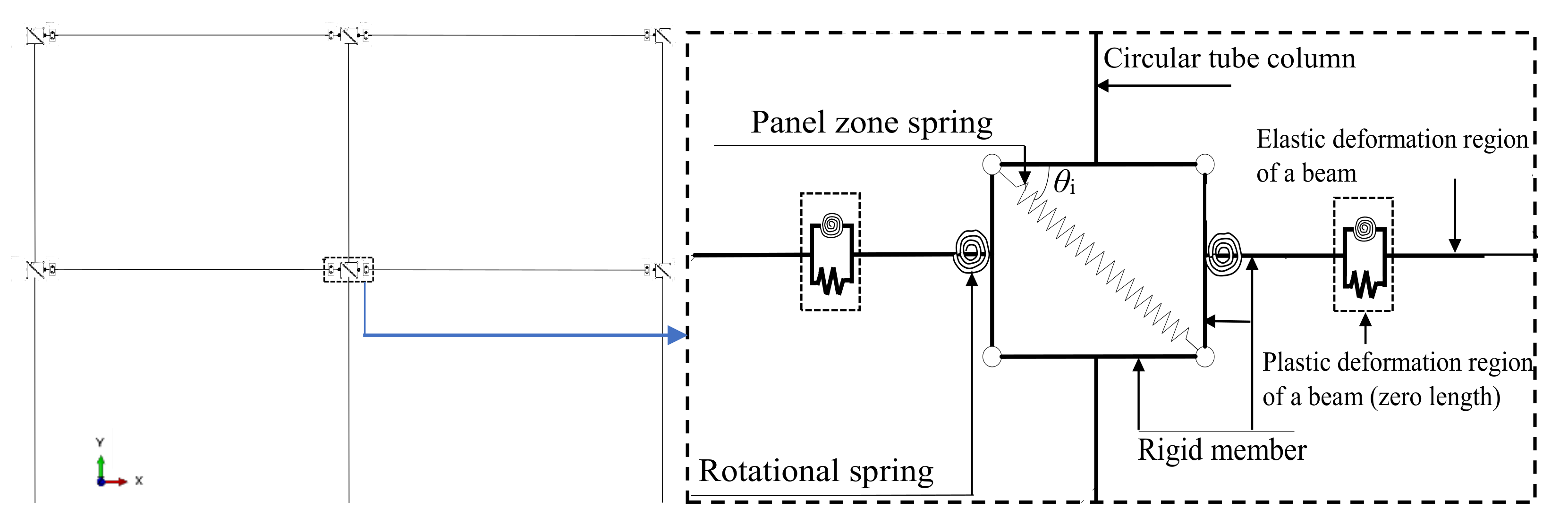
Based on the stress distribution and the deformation mode of the circular-tube-column frames with CSS joints, a component-based model is proposed for the progressive collapse analysis. This efficient component-based model can simulate both the catenary effect and the construction details of the CSS joints for an overall steel frame under a column removal scenario. The equations of all the parameters of the springs in the component-based model are deduced based on the mechanical properties of the CSS joint frame, and the availability of the component-based model to simulate the dynamic nonlinear response of the CSS joint frame under a sudden column removal scenario is validated.
(4)
In order to further simplify the analysis process, dynamic effects can be incorporated into static analysis by using a dynamic increase factor for CSS joint frames. After plenty of static and dynamic analyses are conducted by using the component-based model, a dynamic increase factor of 1.7 suitable for the circular-tube-column frame with CSS is proposed. This dynamic increase factor is smaller than the 2.0 suggested in the DOD guidelines because the CSS joints reduce the maximum deformation of the frame during the progressive collapse.
To sum up, the advantages of CSS joints in resisting progressive collapse were fully demonstrated through force transfer mechanism analysis in this paper, and a simplified component-based model and a suitable dynamic response amplification factor were proposed to guide the design for progressive collapse prevention.

Author Contributions

Conceptualization, X.L. and M.L.; methodology, X.L. and M.L.; software, X.L. and M.L.; validation, X.L. and M.L.; formal analysis, X.L.; investigation, X.L.; resources, X.L. and M.L.; data curation, X.L. and M.L.; writing—original draft, X.L. and L.T.; writing—review and editing, X.L. and L.T.; visualization, X.L.; supervision, X.L.; project administration, X.L.; funding acquisition, X.L. All authors have read and agreed to the published version of the manuscript.

Funding

This research was funded by the Beijing Natural Science Foundation (Grant No. 8214048), the China Postdoctoral Science Foundation (Grant No. 2020M680320), and the Fundamental Research Funds for Beijing University of Civil Engineering and Architecture (Grant No. X21064).

Conflicts of Interest

The authors declare no conflict of interest.

References

  1. DoD. Unified Facilities Criteria (UFC): Design of Buildings to Resist Progressive Collapse, Unified Facilities Criteria (UFC) 4-023-03; Department of Defense: Washington, DC, USA, 2010.
  2. Pearson, C.; Delatte, N. Ronan point apartment tower collapse and its effect on building codes. J. Perform. Constr. Fac. 2005, 19, 172–177. [Google Scholar] [CrossRef] [Green Version]
  3. Pantidis, P.; Gerasimidis, S. Progressive collapse of 3D steel composite buildings under interior gravity column loss. J. Constr. Steel Res. 2018, 150, 60–75. [Google Scholar] [CrossRef]
  4. Zhou, H.; Li, J.; Spencer, B.F., Jr. Multiscale random fields-based damage modeling and analysis of concrete structures. J. Eng. Mech. 2019, 145, 04019045. [Google Scholar] [CrossRef]
  5. Shabani, M.J.; Moghadam, A.S.; Aziminejad, A.; Razzaghi, M.S. Energy-based criteria for assessment of box-section steel columns against progressive collapse. Structures 2021, 34, 2580–2591. [Google Scholar] [CrossRef]
  6. Khandelwal, K.; El-Tawil, S. Pushdown resistance as a measure of robustness in progressive collapse analysis. Eng. Struct. 2011, 33, 2653–2661. [Google Scholar] [CrossRef]
  7. Gerasimidis, S.; Sideri, T. A new partial distributed damage method for progressive collapse analysis of buildings. J. Constr. Steel Res. 2016, 119, 233–245. [Google Scholar] [CrossRef]
  8. Sideri, J.; Mullen, C.L.; Gerasimidis, S.; Deodatis, G. Distributed Column damage effect on progressive collapse vulnerability in steel buildings exposed to an external blast event. J. Perform. Constr. Fac. 2017, 31, 04017077. [Google Scholar] [CrossRef]
  9. Wang, J.; Wang, W. Theoretical evaluation method for the progressive collapse resistance of steel frame buildings. J. Constr. Steel Res. 2021, 179, 106576. [Google Scholar] [CrossRef]
  10. Alashker, Y.; Li, H.; El-Tawil, S. Approximations in progressive collapse modeling. J. Struct. Eng. 2011, 137, 914–924. [Google Scholar] [CrossRef]
  11. Elsanadedy, H.M.; Abadel, A.A. High-fidelity FE models for assessing progressive collapse robustness of RC ordinary moment frame (OMF) buildings. Eng. Fail. Anal. 2022, 136, 106228. [Google Scholar] [CrossRef]
  12. Li, L.; Wang, W.; Chen, Y.; Lu, Y. Experimental investigation of beam-to-tubular column moment connections under column removal scenario. J. Constr. Steel Res. 2013, 88, 244–255. [Google Scholar] [CrossRef]
  13. Elsanadedy, H.; Alrubaidi, M.; Abbas, H.; Almusallam, T.; Al-Salloum, Y. Progressive collapse risk of 2D and 3D steel-frame assemblies having shear connections. J. Constr. Steel Res. 2021, 179, 106533. [Google Scholar] [CrossRef]
  14. Mageirou, G.E.; Lemonis, M.E. Influence of imperfections on the progressive collapse of steel moment resisting frames. J. Constr. Steel Res. 2021, 183, 106744. [Google Scholar] [CrossRef]
  15. Subki, N.E.A.; Mansor, H.; Hamid, Y.S.; Parke, G.A.R. The development of a moment-rotation model for progressive collapse analysis under the influence of tensile catenary action. J. Constr. Steel Res. 2021, 187, 106960. [Google Scholar] [CrossRef]
  16. Daneshvar, H.; Driver, R.G. Performance evaluation of WT connections in progressive collapse. Eng. Struct. 2018, 167, 376–392. [Google Scholar] [CrossRef]
  17. Zhong, W.; Meng, B.; Hao, J. Performance of different stiffness connections against progressive collapse. J. Constr. Steel Res. 2017, 135, 162–175. [Google Scholar] [CrossRef]
  18. Qian, K.; Lan, X.; Li, Z.; Li, Y.; Fu, F. Progressive collapse resistance of two-storey seismic configured steel sub-frames using welded connections. J. Constr. Steel Res. 2020, 170, 106117. [Google Scholar] [CrossRef]
  19. Li, H.; Cai, X.; Zhang, L.; Zhang, B.; Wang, W. Progressive collapse of steel moment-resisting frame subjected to loss of interior column: Experimental tests. Eng. Struct. 2017, 150, 203–220. [Google Scholar] [CrossRef]
  20. Alrubaidi, M.; Elsanadedy, H.; Abbas, H.; Almusallam, T. Investigation of different steel intermediate moment frame connections under column-loss scenario. Thin Walled Struct. 2020, 154, 106875. [Google Scholar] [CrossRef]
  21. Cortés, G.; Liu, J. Behavior of conventional and enhanced gravity connections subjected to column loss. J. Constr. Steel Res. 2017, 133, 475–484. [Google Scholar] [CrossRef]
  22. Meng, B.; Zhong, W.; Hao, J.; Tan, Z. Improved steel frame performance against progressive collapse with infill panels. J. Constr. Steel Res. 2019, 158, 201–212. [Google Scholar] [CrossRef]
  23. Chen, C.; Qiao, H.; Wang, J.; Chen, Y. Progressive collapse behavior of joints in steel moment frames involving reduced beam section. Eng. Struct. 2020, 225, 111297. [Google Scholar] [CrossRef]
  24. Yu, Y.; Lan, L.; Chen, Z.; Huang, J. Mechanical and seismic behaviors of bottom-flange-bolted upper-flange-welded through-diaphragm connections. J. Constr. Steel Res. 2019, 156, 86–95. [Google Scholar] [CrossRef]
  25. Han, Q.; Li, X.; Liu, M.; Spencer, B.F., Jr. Performance analysis and macromodel simulation of steel frame structures with beam-column joints using cast steel stiffeners for progressive collapse prevention. Thin Walled Struct. 2019, 140, 404–415. [Google Scholar] [CrossRef]
  26. Feng, D.C.; Shi, H.R.; Parisi, F.; Brunesi, E.; Wang, C. Efficient numerical model for progressive collapse analysis of prestressed concrete frame structures. Eng. Fail. Anal. 2021, 129, 105683. [Google Scholar] [CrossRef]
  27. Wang, F.; Yang, J.; Pan, Z. Progressive collapse behaviour of steel framed substructures with various beam-column connections. Eng. Fail. Anal. 2020, 109, 104399. [Google Scholar] [CrossRef]
  28. Lin, S.C.; Yang, B.; Kang, S.B.; Xu, S.Q. A new method for progressive collapse analysis of steel frames. J. Constr. Steel Res. 2019, 153, 71–84. [Google Scholar] [CrossRef]
  29. Ding, Y.; Song, X.; Zhu, H.T. Probabilistic progressive collapse analysis of steel frame structures against blast loads. Eng. Struct. 2017, 147, 679–691. [Google Scholar] [CrossRef]
  30. Liu, M. Progressive collapse design of seismic steel frames using structural optimization. J. Constr. Steel Res. 2011, 67, 322–332. [Google Scholar] [CrossRef]
  31. Dinu, F.; Marginean, I.; Dubina, D. Experimental testing and numerical modelling of steel moment-frame connections under column loss. Eng. Struct. 2017, 151, 861–878. [Google Scholar] [CrossRef]
  32. Jiang, Z.Q.; Chen, M.L.; Yang, Z.S.; Li, X.Y.; Cai, C. Cyclic loading tests of self-centering prestressed prefabricated steel beam-column joint with weakened FCP. Eng. Struct. 2022, 252, 113578. [Google Scholar] [CrossRef]
  33. Cheng, G.; Zhou, X.; Liu, J.; Chen, Y.F. Seismic behavior of circular tubed steel-reinforced concrete column to steel beam connections. Thin Walled Struct. 2019, 138, 485–495. [Google Scholar] [CrossRef]
  34. Khanouki, M.M.A.; Sulong, N.H.R.; Shariati, M.; Tahir, M.M. Investigation of through beam connection to concrete filled circular steel tube (CFCST) column. J. Constr. Steel Res. 2016, 121, 144–162. [Google Scholar] [CrossRef]
  35. Zhou, X.; Cheng, G.; Liu, J.; Yang, Y.; Chen, Y.F. Shear transfer behavior at the circular tubed column-steel beam interface. Thin Walled Struct. 2019, 137, 40–52. [Google Scholar] [CrossRef]
  36. Mou, B.; Li, Y.; Wang, F.; Pan, W.; Zhao, Y. Flexural behavior of a novel high-strength RCFST column-to-column connection. Thin Walled Struct. 2021, 159, 107274. [Google Scholar] [CrossRef]
  37. Yang, Z.; Deng, H.; Hu, X. Strength of longitudinal X-type plate-to-circular hollow section (CHS) connections reinforced by external ring stiffeners. Thin Walled Struct. 2018, 131, 500–518. [Google Scholar] [CrossRef]
  38. Liu, M.; Li, X.; Han, Q.; Lu, Y. Theoretical research on force transmission mechanism and bearing capacity of round steel tube column-H-shaped steel beam cast-steel connection joint. J. Build. Struct. 2019, 40, 200–209. (In Chinese) [Google Scholar]
  39. Khandelwal, K.; El Tawil, S.; Kunnath, S.K.; Lew, H.S. Macromodel-Based Simulation of Progressive Collapse: Steel Frame Structures. J. Struct. Eng. 2008, 134, 1070–1078. [Google Scholar] [CrossRef]
  40. Lee, C.; Kim, S.; Lee, K. Parallel axial-flexural hinge model for nonlinear dynamic progressive collapse analysis of welded steel moment frames. J. Struct. Eng. 2010, 136, 165–173. [Google Scholar] [CrossRef]
  41. Yu, J.; Tan, K.H. Experimental and numerical investigation on progressive collapse resistance of reinforced concrete beam column sub-assemblages. Eng. Struct. 2013, 55, 90–106. [Google Scholar] [CrossRef]
  42. Bao, Y.; Kunnath, S.K.; El-Tawil, S.; Lew, H.S. Macromodel-based simulation of progressive collapse: RC frame structures. J. Struct. Eng. 2008, 134, 1079–1091. [Google Scholar] [CrossRef]
  43. Fu, Q.; Yang, B.; Hu, Y.; Xiong, G.; Nie, S.; Zhang, W.; Dai, G. Dynamic analyses of bolted-angle steel joints against progressive collapse based on component-based model. J. Constr. Steel Res. 2016, 117, 161–174. [Google Scholar] [CrossRef]
  44. Zhao, Z.; Jian, X.; Liang, B.; Liu, H. Progressive collapse assessment of friction damped post-tensioned steel frames based on a simplified model. Structures 2020, 23, 447–458. [Google Scholar] [CrossRef]
  45. Liu, C.; Tan, K.H.; Fung, T.C. Component-based steel beam–column connections modelling for dynamic progressive collapse analysis. J. Constr. Steel Res. 2015, 107, 24–36. [Google Scholar] [CrossRef]
  46. Stylianidis, P.M.; Nethercot, D.A. Modelling of connection behaviour for progressive collapse analysis. J. Constr. Steel Res. 2015, 113, 169–184. [Google Scholar] [CrossRef]
  47. GB50017-2003; Code for Design of Steel Structures. Ministry of Housing and Urban–Rural Development of the People’s Republic of China: Beijing, China, 2003.
  48. GB50009-2012; Load Code for the Design of Building Structures. Ministry of Housing and Urban–Rural Development of the People’s Republic of China: Beijing, China, 2012.
  49. Khandelwal, K.; El-Tawil, S. Collapse behavior of steel special moment resisting frame connections. J. Struct. Eng. 2007, 133, 646–655. [Google Scholar] [CrossRef]
  50. Han, Q.; Li, X.; Liu, M.; Spencer, B.F., Jr. Experimental investigation of beam-column joints with cast steel stiffeners for progressive collapse prevention. J. Struct. Eng. 2019, 145, 04019020. [Google Scholar] [CrossRef]
  51. Wang, K.; Li, G.; Yang, T. The performance of restrained steel beams considering catenary effect under distributed loads (I)-Theoretical model. Chin. Civ. Eng. J. 2010, 43, 8–12. (In Chinese) [Google Scholar]
  52. EN1993-1-1; Eurocode 3: Design of Steel Structures, Part 1–3: General Rules and Rules for Buildings. European Committee for Standardization: Brussels, Belgium, 2005.
Figure 1. Two-story circular-tube-column frame (unit: mm). (a) Plan view; (b) Elevation view.
Buildings 12 01049 g001
Figure 2. Detailed models of circular-tube-column frames with different joints: (a) Model Ac; (b) Model Bc.
Buildings 12 01049 g002
Figure 3. CSS for circular-tube-column frame (unit: mm): (a) Three-dimensional diagram; (b) Three orthographic views.
Buildings 12 01049 g003
Figure 4. Displacement–time curves of different detailed solid-element models simulating the test.
Buildings 12 01049 g004
Figure 5. Displacement–time history curves of the interior column bottoms in models Ac and Bc: (a) Load (i); (b) Load (ii); (c) Load (iii); (d) Load (iv).
Buildings 12 01049 g005aBuildings 12 01049 g005b
Figure 6. Equivalent plastic strain cloud diagram of model Ac at 15 s under load (iii).
Buildings 12 01049 g006
Figure 7. Mises stress cloud diagram of model Ac at 15 s under load (iii).
Buildings 12 01049 g007
Figure 8. Equivalent plastic strain of model Bc when the vertical displacement of the interior column reached its maximum value under load (iii).
Buildings 12 01049 g008
Figure 9. Mises stress of model Bc when the vertical displacement of the interior column reached its maximum value under load (iii).
Buildings 12 01049 g009
Figure 10. Time history curves of the displacements of the interior columns and the maximum equivalent plastic strains at the buckled regions under load (iv): (a) Model Ac; (b) Model Bc.
Buildings 12 01049 g010
Figure 11. Subassembly two-span frame extracted from model Bc (model S): (a) Boundary conditions; (b) Equivalent plastic strain distribution.
Buildings 12 01049 g011
Figure 12. Axial tension–bending moment interaction at beam ends of model S.
Buildings 12 01049 g012
Figure 13. Schematic diagram of the simplified process of the load.
Buildings 12 01049 g013
Figure 14. Component-based model of the frame with circular tube columns and CSS joints.
Buildings 12 01049 g014
Figure 15. Schematic diagram of Δ l 1 c .
Buildings 12 01049 g015
Figure 16. Schematic diagram of Δ l 2 c .
Buildings 12 01049 g016
Figure 17. Deformation schematic diagram of the panel zone spring.
Buildings 12 01049 g017
Figure 18. Different models of the CSS joint with circular tube columns to simulate the test specimen in reference [38]: (a) Detailed solid-element model; (b) Component-based model.
Buildings 12 01049 g018
Figure 19. The component-based model (model M) remodeled from the detailed solid-element model Bc in Section 3.
Buildings 12 01049 g019
Figure 20. The vertical displacements of the bottoms of the interior columns in the component-based model (model M) and the detailed solid-element model (model Bc).
Buildings 12 01049 g020
Figure 21. Displacements of the bottom of the interior column in dynamic and static analyses under gradually increasing loads (β = 0.9–2.6): (a) when β = 0.9–1.7; (b) when β = 1.8–2.6.
Buildings 12 01049 g021
Figure 22. Maximum vertical displacement versus β in the dynamic and static analyses.
Buildings 12 01049 g022
Table 1. Load cases.
LoadDead Load (kN·m−2)Live Load (kN·m−2)
i1.00.5
ii3.22.0
iii5.112.0
iv5.120.0
Table 2. Displacements of the interior column bottoms in models Ac and Bc.
Load Maximum Displacement (mm)Final Displacement (mm)
Model AcModel BcModel AcModel Bc
i−8.65−7.49−5.47−4.80
ii−44.61−38.02−25.96−22.34
iii−202.04−115.99−202.04−105.97
iv−1016.92−451.97−1016.92−451.97
Table 3. The time when the plastic strain occurred in model Ac and model Bc.
LoadThe Time When Plastic Strain Occurred (s)
Model AcModel Bc
i--
ii13.05913.071
iii13.05213.054
iv13.05213.054
Table 4. Initial rotational stiffness of the test specimens, the detailed solid-element models, and the component-based models.
SpecimenColumn Thickness
t (mm)
Test Results
K1
(kN·m·rad−1)
Detailed Solid-Element Model Results
K2 (kN·m·rad−1)
Component-Based Model Results
K3 (kN·m·rad−1)
K2/K1K3/K1
1815,46713,79414,0210.8920.907
21016,02216,01116,1320.9991.007
31219,89318,06818,7630.9080.943
Table 5. Parameterized analysis results of the initial rotational stiffness.
Specimenhb
(mm)
B
(mm)
t
(mm)
hr
(mm)
l1
(mm)
l2
(mm)
Detailed Solid-Element Model
K2 (kN·m·rad−1)
Component-Based Model
K3 (kN·m·rad−1)
K3/K2
11852038351407.51592.513,80013,0160.943
221015,03413,8930.924
323516,15015,9320.987
118515310351407.51592.5892691231.022
417813,00313,9761.075
520316,03516,9231.055
11852038351407.51592.513,79414,0211.016
61016,01116,1321.008
71218,06818,7631.038
11852038351407.51592.513,80013,0160.943
84014,06913,4750.958
94514,29613,9720.977
11852038351407.51592.513,80013,0160.943
101842.511,91710,3340.867
112092.510,04894520.941
Publisher’s Note: MDPI stays neutral with regard to jurisdictional claims in published maps and institutional affiliations.

