1. Introduction
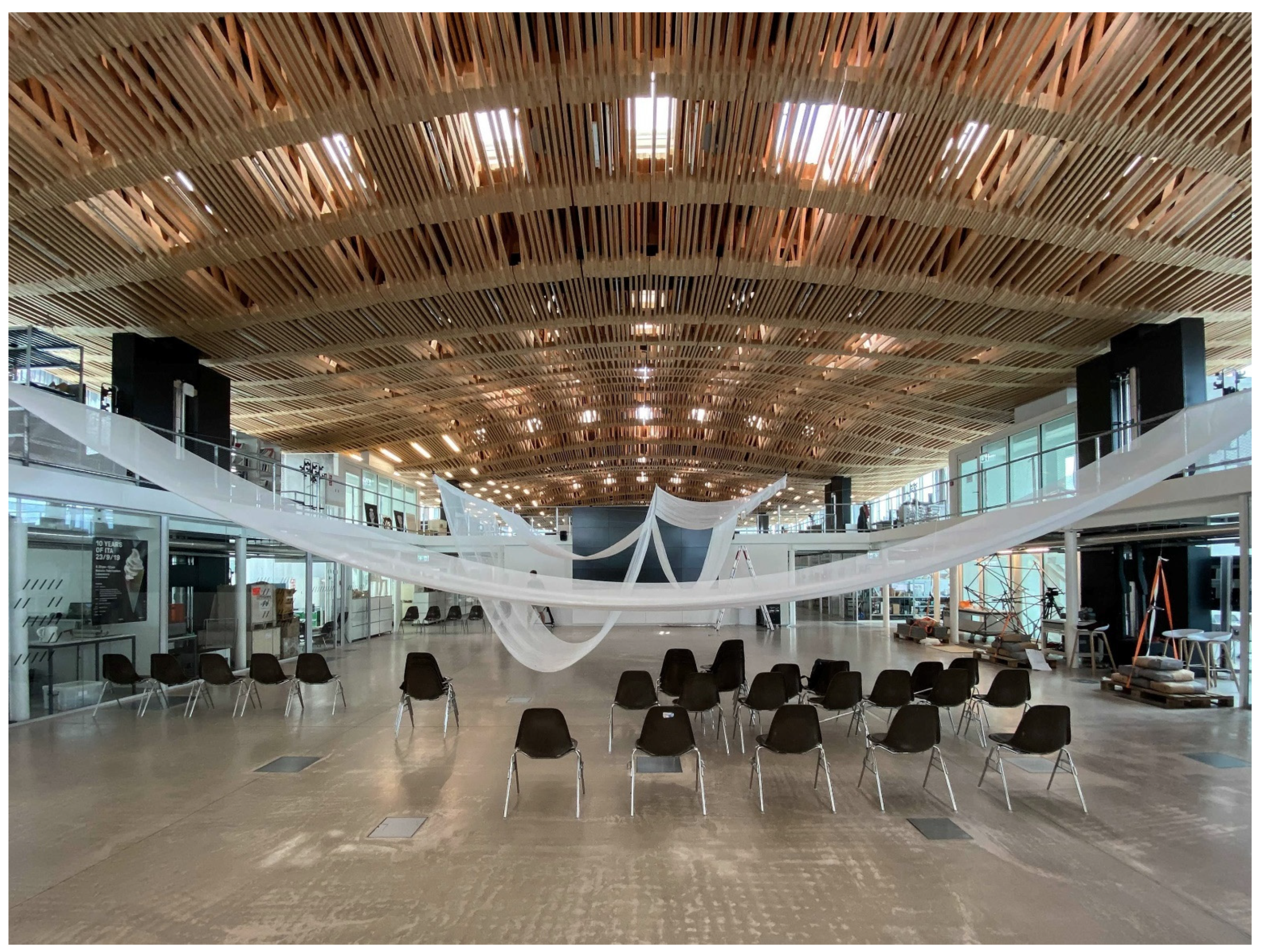
The Canopy (
Figure 1) is a temporary lightweight installation made of wide perforated fabric strips hanging from steel cables inside the
Kiesofenhalle, a former cellulose factory in Attisholz, Switzerland. The project aimed at creating a venue for the 3-day event of the International fib Symposium on “Conceptual Design of Structures” [
1], which was held in September 2021 and hosted over 150 participants. In conjunction with the conference, an exhibition explored the Swiss contribution to structural design looking at design methods and exemplary projects. Particular emphasis was given to the use of physical models for form-finding and graphic statics, represented by the work of renowned Swiss engineers such as Heinz Isler (1926–2009) and Robert Maillart (1872–1940).
The objective of this paper is to illustrate the design, fabrication, and erection processes of
The Canopy. Drawing inspiration from the work of Sekler [
2], this paper elaborates on the strategy to integrate and balance the relationship between structure, construction, and tectonics. These three aspects are addressed from three perspectives throughout
The Canopy’s design process: conceptual design, fabrication and assembly, and final spatial expression. The paper shows the instrumental role of graphic statics in unfolding the relationship between form and forces and thus in reconciling spatial artistic needs and structural requirements from the conceptual design phase. Graphic statics provides an ideal medium for integrating the design of structure, construction, and tectonics, with the aim of fostering a collaborative and creative interaction between architecture and engineering.
The Canopy’s design process exemplifies the significance of this collaboration.
2. Background
The
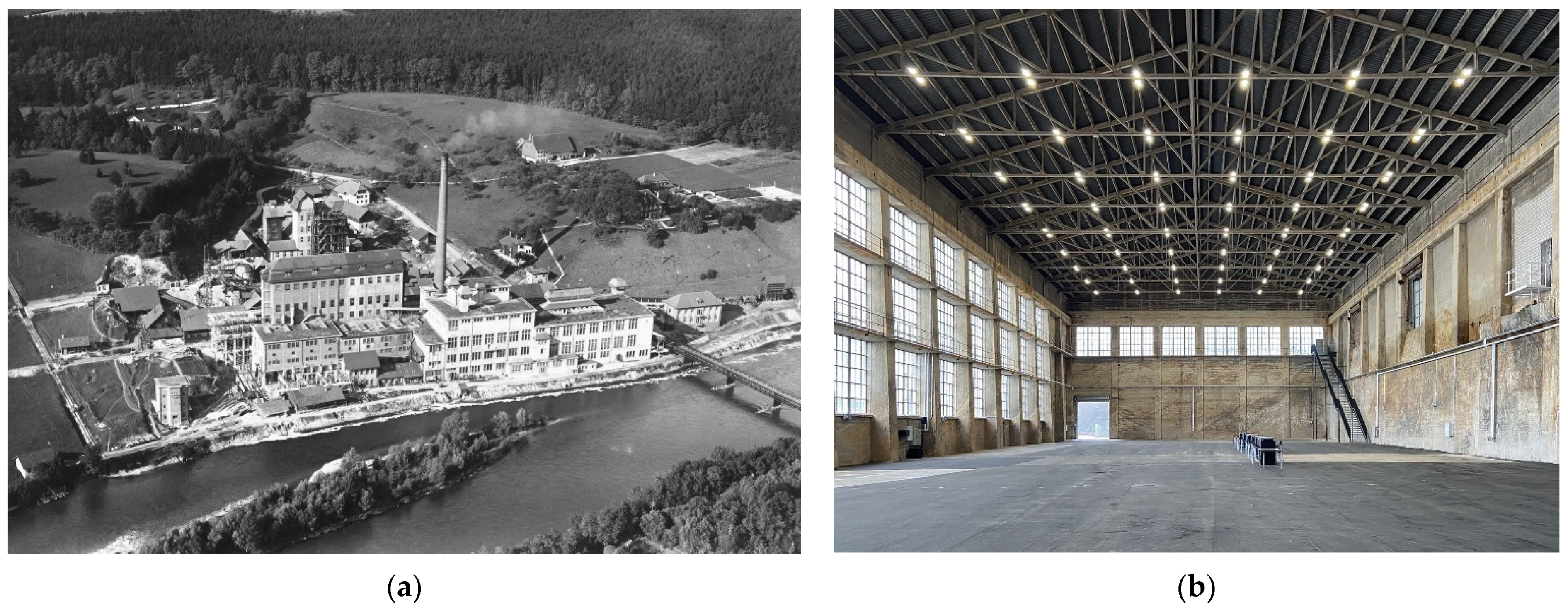
Kiesofenhalle is a former industrial hall located inside the industrial estate of Cellulose Attisholz AG, a company that operated for over 100 years in the paper production industry. The company was founded in 1881, merged with the Balsthal paper mill in 1914, and finally was acquired the German company Hakle in 1983 [
3]. Since the end of 2016, in collaboration with the municipality of Riedholz and the Canton of Solothurn, the area has gone through radical transformation that aimed to turn it into a mixed-use artistic and cultural district while preserving the original cultural values of the industrial buildings [
4] (
Figure 2a).
The overall size of
Kiesofenhalle (
Figure 2b) exceeds 3000 m
2 and reaches a maximum height of 17.5 m. The hall served as a storage for raw material whose chemical properties greatly enhanced the risk of corrosion of metal elements. For this reason, even the roof slender trusses are in fact made of concrete, thus remarking the strong industrial expression of the hall. Furthermore, the building’s exceptionally tall scale and large, continuous south-facing windows contribute to the creation of an almost sacred spatial experience similar to a modern concrete church.
The enormous size of the hall called for a series of interventions that would frame the space and create a human-scale venue to accommodate the different functions required by the organizer of the conference. In particular, it was necessary to separate the hall into a conference space, an exhibition area, and a registration and catering area.
Apart from a limited amount of time for on-site assembly—only three days—another requirement was to intervene on the existing structure as little as possible. This excluded the possibility of using the existing roof trusses as supports, or anchoring elements to the ground. Moreover, the possibility to introduce high external forces in the walls was also limited. Because of these constraints, the design was defined as a lightweight structure made of parallel steel cables and perforated fabric strips hanging from above. The undulating geometry of the fabric allowed for a continuous generation of vertical partitions and of horizontal surfaces with different heights above ground. Thanks to this simple logic, the elements could be pre-fabricated off-site and easily transported and assembled in the given time frame. In this sense, the combination of cables and textile elements represented a suitable way to generate the desired spaces, while complying with the given requirements, as demonstrated by several reference projects [
5,
6,
7,
8].
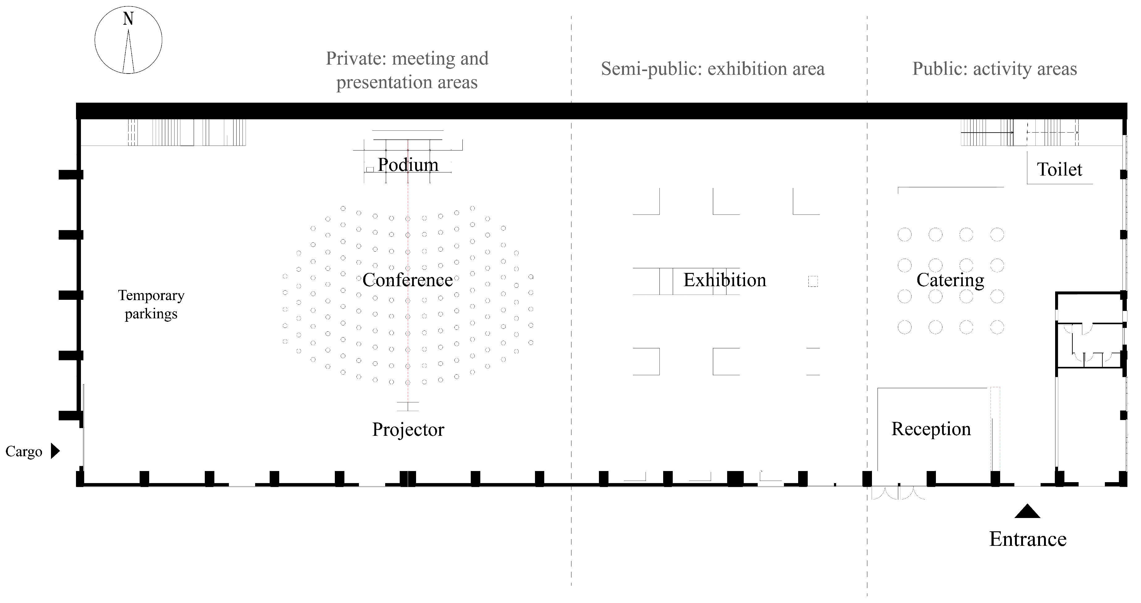
In response to the conference’s functional requirements, the hall was divided into three main areas based on different privacy levels: a public area with registration desks and a catering area; a semi-public exhibition area; and a relatively intimate auditorium for lectures and discussions (
Figure 3). In the auditorium, the height of the fabric had to be higher than 4.8 m to avoid obstructing the projector but less than 7 m in order to create the feeling of an enclosed space. Conversely, the more public character of the exhibition and reception areas called for more open spaces, with fabric heights reaching up to 11 m above ground. The division between these three functional areas was achieved solely through the geometry of
The Canopy. As better explained in
Section 4.1.1, by manipulating the lower boundary line of the fabric sags, it was possible to create a subtle spatial division between the different areas, thus suggesting a new spatial order to the enormous hall. Aspects related to the acoustics of the diverse spaces were not considered as integral part of the design process since the Symposium program did not include parallel sessions, and the catering and exhibition areas were not used during the presentations.
Based on the design concept, to achieve the sensation of lightness and a floating effect,
The Canopy’s supporting structure had to be designed to be as invisible as possible. Therefore, when conceiving the structural system, we sought to minimize both the size and number of components. The slender and clear supporting structure for
The Canopy was made of simple steel cables. The catenary line that they draw as they span over the hall recalls the historical methods of form-finding using hanging models, also relating to the content of the exhibition. The use of hanging models as a design tool to determine the optimal form for structures is a technique used by many architects and engineers, especially before the introduction of analytical methods. Antoni Gaudí (1852–1926) already used the hanging model as a three-dimensional design tool to determine the optimal form for structures subjected to purely compressive loads at the turn of the 20th century, and ultimately obtained the structural form of the
Sagrada Familia [
9]. Later on, the Swiss engineer Heinz Isler has been a key protagonist in the use of this technique to determine the optimal shape for shell structures [
10]. For them, the physical model entails not only a method for determining the ideal shape, but also a method of thought and operation [
11]. Similarly, graphic statics was used as a key method in the design of
The Canopy. 3. Methodology
In the design process of
The Canopy, the simultaneous requirements related to form and forces were reconciled using graphic statics. Graphic statics is a set of geometric rules that allow unfolding in a diagrammatic way the relationship between the form of a structure in static equilibrium and the forces within it [
12,
13,
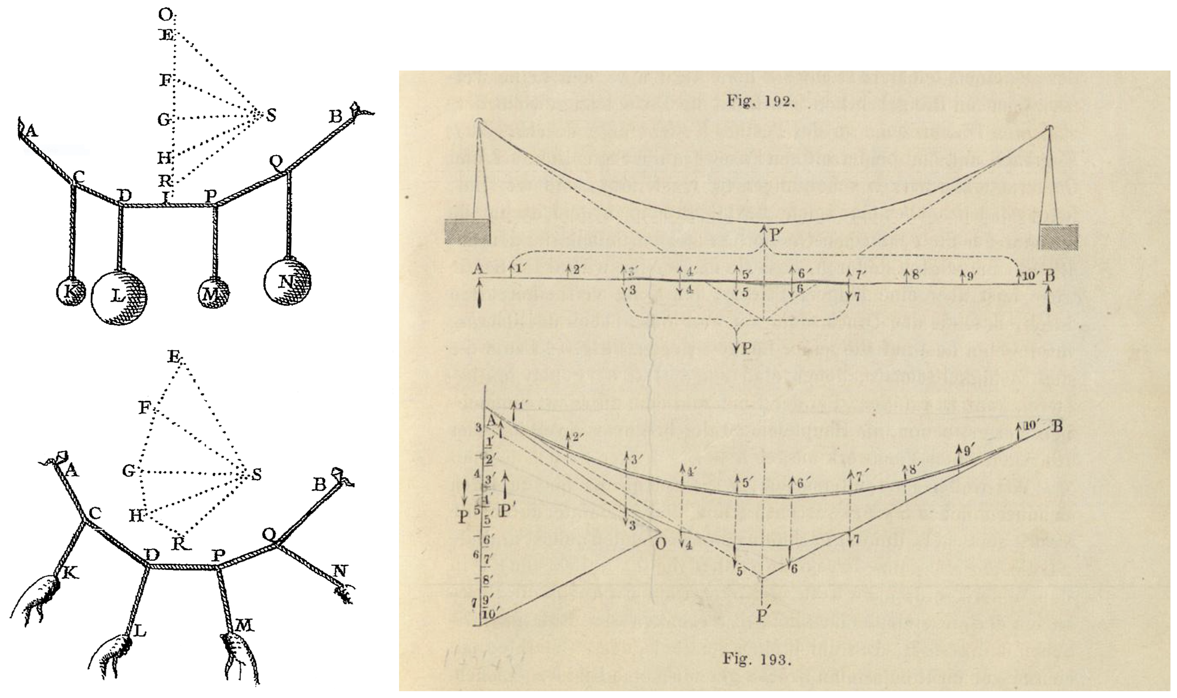
14]. Several scientists contributed to the development and formalization of graphic statics starting from the 16th century. Interestingly, many of the early works related to graphic statics make use of the hanging models under given loads to illustrate the basics of the method [
15,
16,
17] (
Figure 4a). Graphic statics was eventually formalized and expanded by the German engineer and ETH Professor Karl Culmann in his two volumes of
Die Graphische Statik [
18] (
Figure 4b). His work on graphic statics significantly influenced renowned Swiss engineers such as Robert Maillart (1872–1940) [
19], and this legacy remains an integral part of the teaching of structures at ETH Zurich to these days [
20]. The use of graphic statics as the structural design tool for the canopy is a tribute to this legacy.
It is worth mentioning that this approach is radically different compared to conventional Finite Element Analysis (FEA) software for structural engineering. In fact, unlike graphic statics, FEA software is based on analytical models that are solved through numerical techniques [
21]. When used for design purposes, FEA shows several shortcomings as it generally tends to conceal the relationship between form and forces. This often hinders the possibility to operate on a conceptual level and to create an effective dialogue between architects and engineers [
20]. Conversely, the diagrammatic nature of graphic statics offers a common ground between disciplines and an effective design tool for the conceptual design phase of a structure [
22]. Additionally, it also facilitates the early integration of the art and technology of structures as part of the architectural design process by reducing the design of load-bearing structures to basic equilibrium concepts and by translating calculations into simple geometric operations [
23,
24].
In addition to its visual nature, the constructive and generative nature of the vector-based operations of graphic statics enables easy integration with digital design methods that began to emerge in architecture in the early 2000s [
25,
26,
27,
28]. Digital implementations of the method allowed for overcoming the inherent limitations of manual applications and proved effective for the creation of architectural spaces informed by form and forces simultaneously [
29,
30,
31]. A simple digital implementation of graphic statics has also been used in the design of
The Canopy for rapid form-finding and calculation of forces using Grasshopper3D.
4. Case Presentation: Structure, Construction, and Tectonics
To elaborate
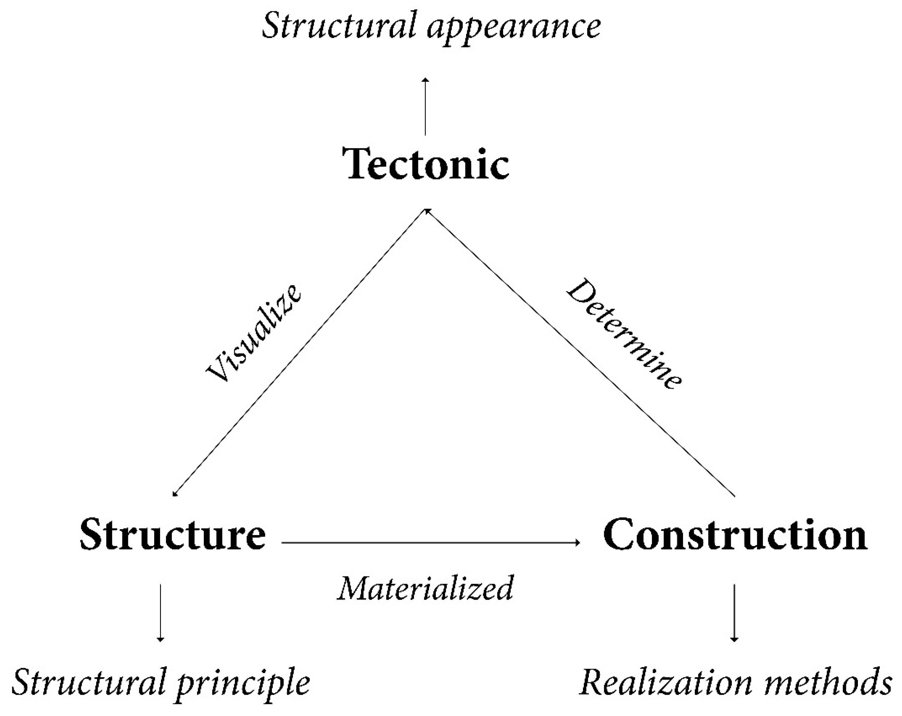
The Canopy’s design and fabrication methods, this paper utilises Eduard F. Sekler’s critical aspects of structural design to dissect its embedded structural thinking: structure, construction, and tectonics [
2]. In his article, Structure, Construction, and Tectonics, Sekler defines structure as an “intangible concept” that is “realized through construction and visualized through tectonics” [
2]. Thus, structures are bonded to the construction technique and the perceptual representation of the tectonic form (
Figure 5). Based on this understanding, the following section of the paper describes how graphic statics was used to inform the design in order to facilitate early collaboration between the architects and engineers.
4.1. Structure: A Lightweight and Minimal Intervention
The most challenging aspect of intervening in the building was transforming the over-scale floor height into a human-scale exhibition and lecture space with the least amount of means. This led to the main design concept: designing a small, nested space within the building with a limited height above ground that separates three functional areas with varying dynamic and static partitioning. Due to the spatial qualities of the original structure, it was decided early on to create this enclosure out of a translucent or perforated material. As such, the installation would limit the space while preserving the context of the surrounding scene. The three main functional areas were identified based on the main entrance’s location, located in the south-east corner of the building (
Figure 3).
The project was conceived as a lightweight spatial installation, a translucent, abstract, white fabric canopy that floats within the hall in a gradual wave pattern. Each fabric fold corresponds to the axis of the building’s original concrete trusses, achieving geometric and visual continuity. While defining the space beneath it, the fabric separates the different functions of the private density through the fluctuating height changes of the fabric in the vertical direction, linking the entire space in a holistic and continuous form while meeting the requirements for the conference activities. The free-falling, hanging form of the fabric seeks to recall the image of paper rolls that were once produced at Attisholz and the logic of the catenary curve as a pure structurally-informed shape. This interplay between form and force was also addressed repeatedly in the exhibition that was organized in conjunction with the conference.
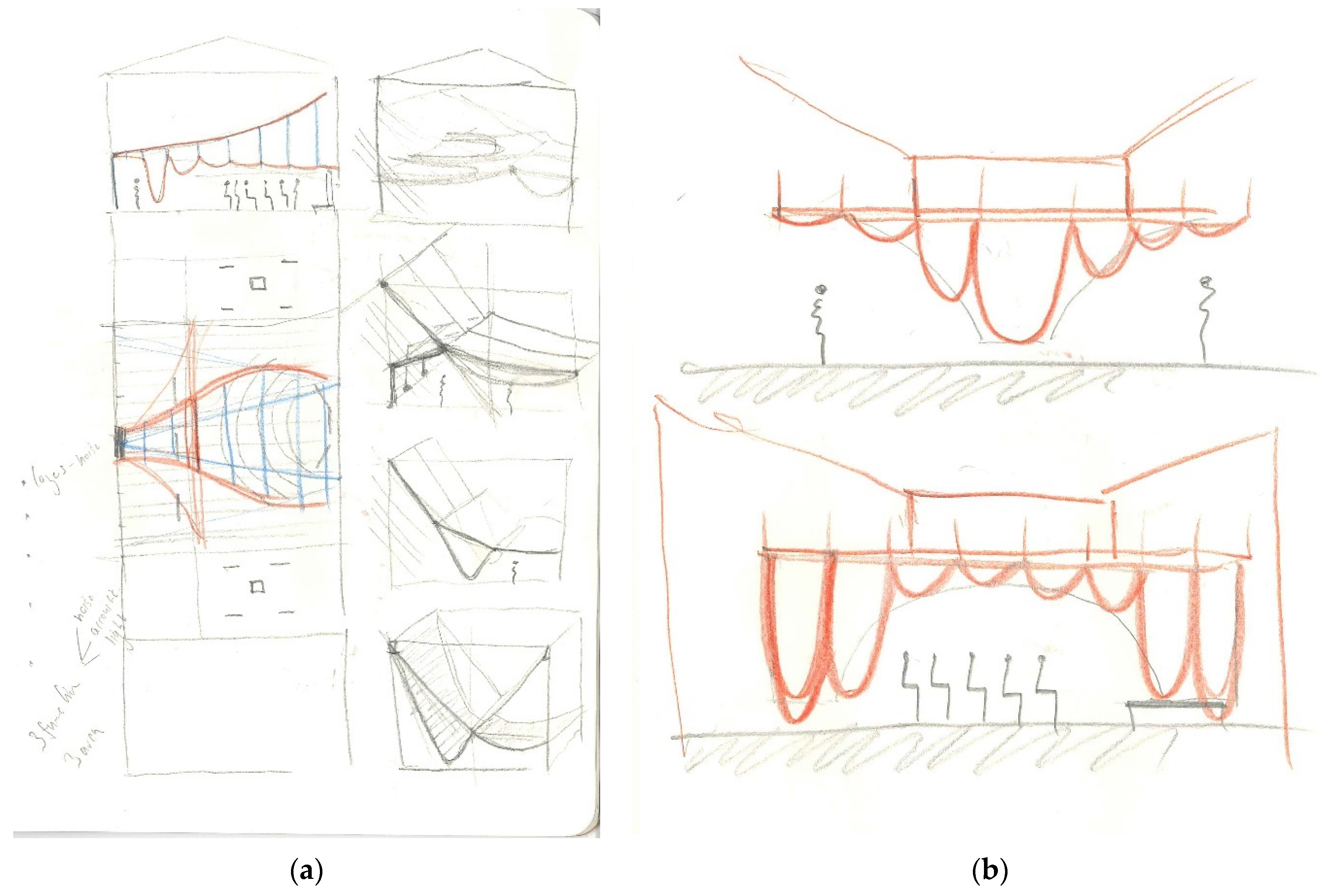
From the beginning of the design process, the diagrammatic nature of graphic statics allowed for the intuitive expression, rapid communication, and visual definition of these structural forms during the design brainstorming phases (
Figure 6).
Due to the enormous size of the canopy, with the fabric sagging up to 6.5 m, the choice of fabric properties such as porosity, weight, and elasticity had a significant impact on the final result. To simulate the material as realistically as possible, several 1:1 mock-ups were built and tested (
Figure 7). In particular, these tests showed that fabrics that were too light could not easily result in a precise catenary geometry for the lack of sufficient self-weight. Heavier fabrics, despite generating cleaner catenary lines, proved to be excessively opaque, thus considerably weakening the desired architectural image and the relationship with the context. Additionally, fire safety represented an additional requirement that excluded the possibility to use several types of materials. The final choice was a polyethylene 2-m wide white mesh of 5 mm and a weight of 0.1 kg/m
2.
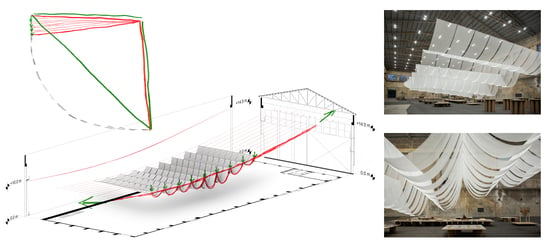
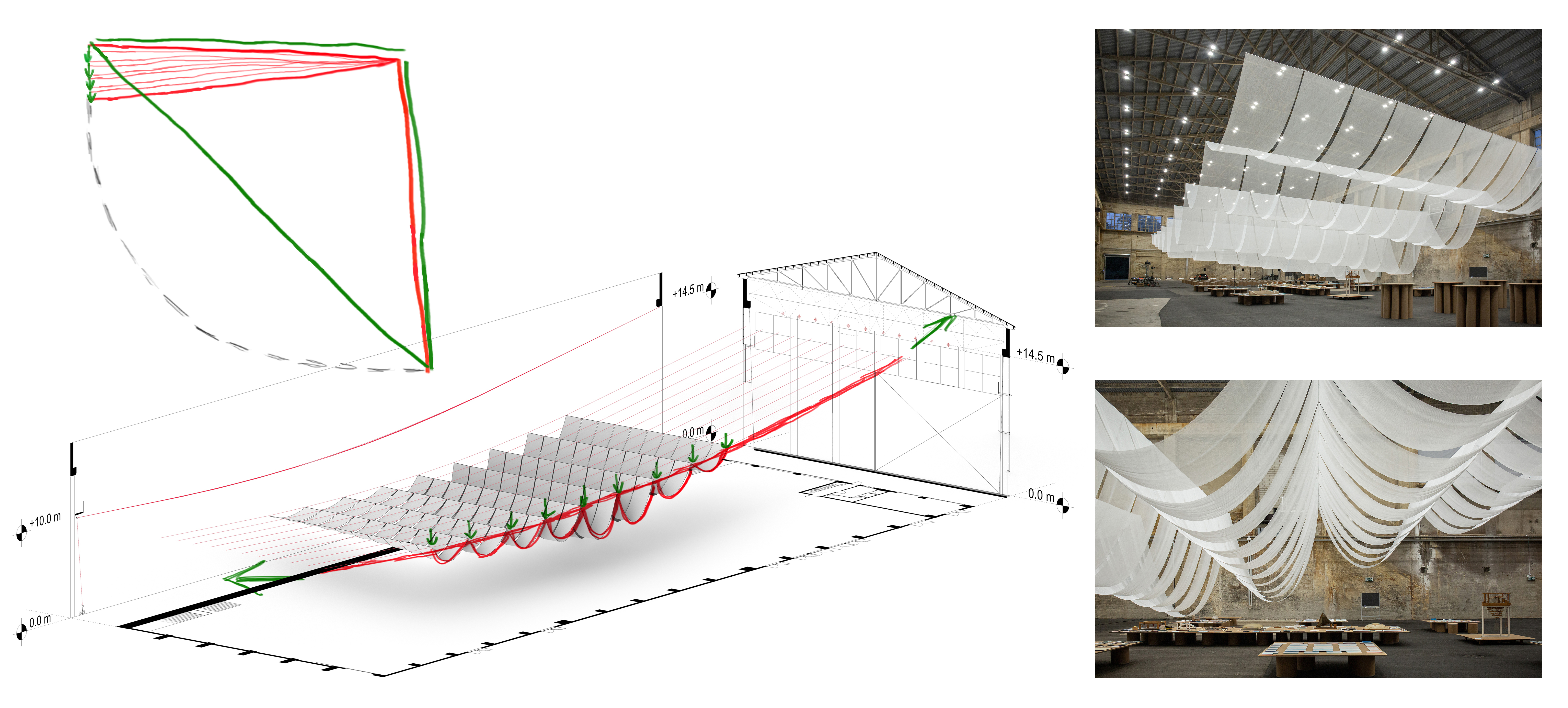
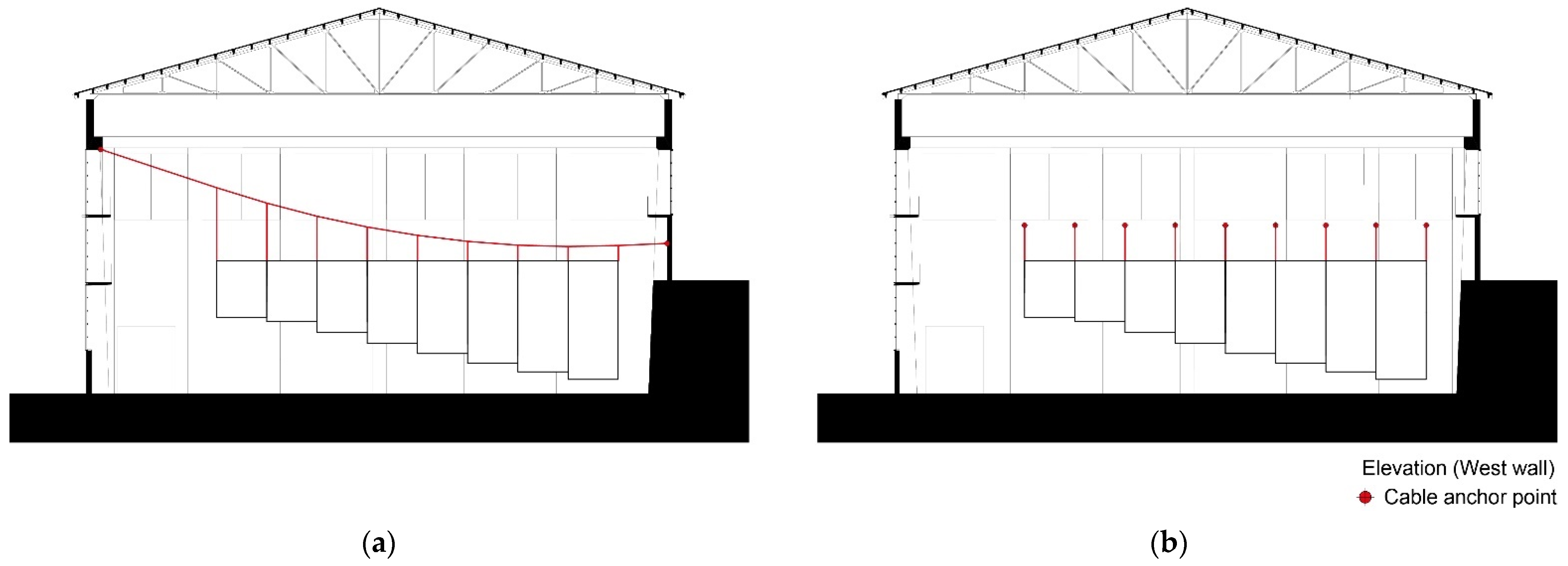
Before the detailed design of the hanging structure, a crucial design step was to decide whether to suspend the fabric using longitudinal or transversal rows of cables in the
Kiesofenhalle. Even though the building footprint is symmetrical in its short section, the north side of the façade is almost entirely closed with a solid retaining wall, whereas the south side of the building has stunning continuous windows that give the building a sense of breathing. Due to the shorter transversal distance, the first test comprised an array of parallel cables along this direction (
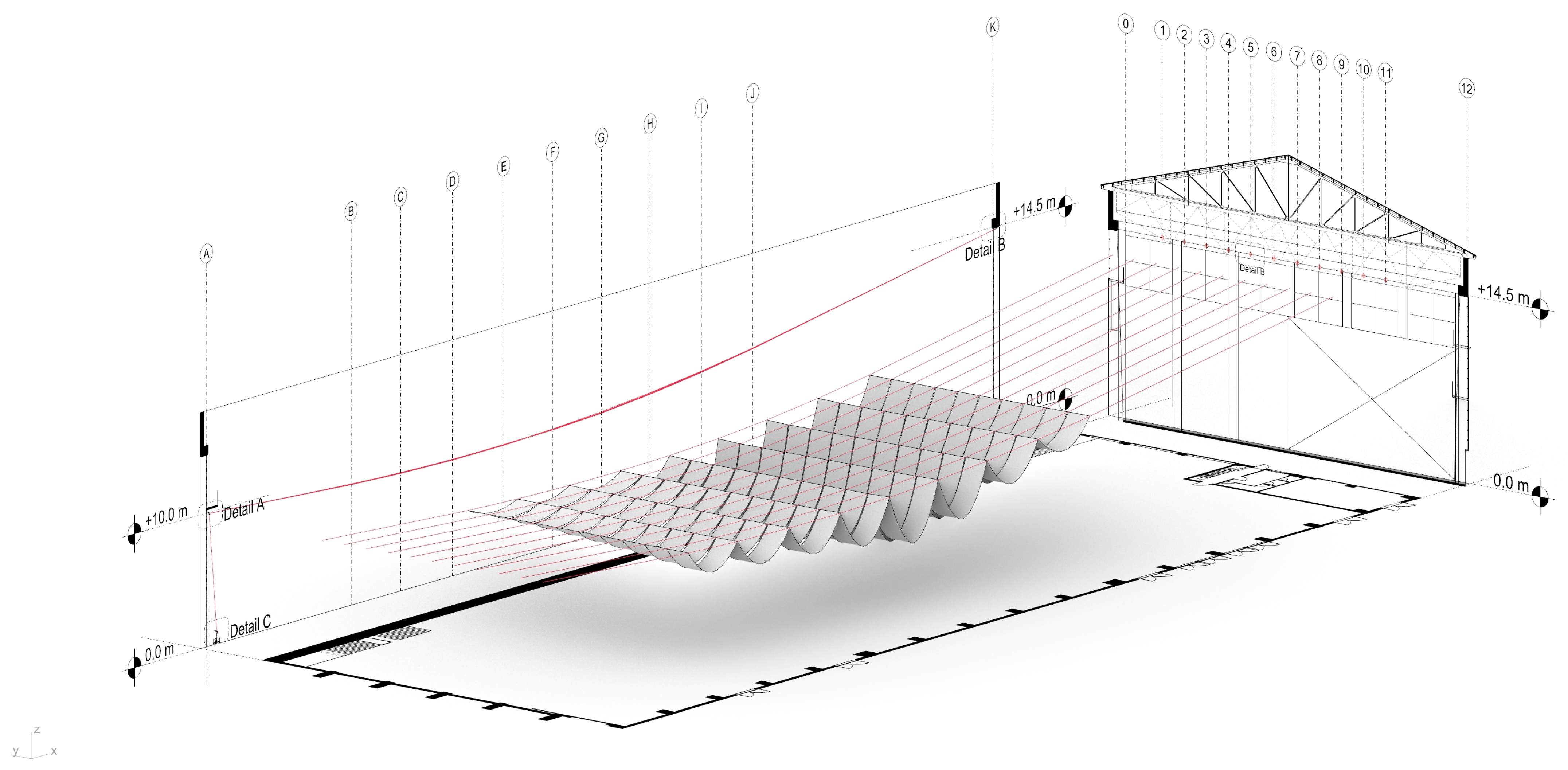
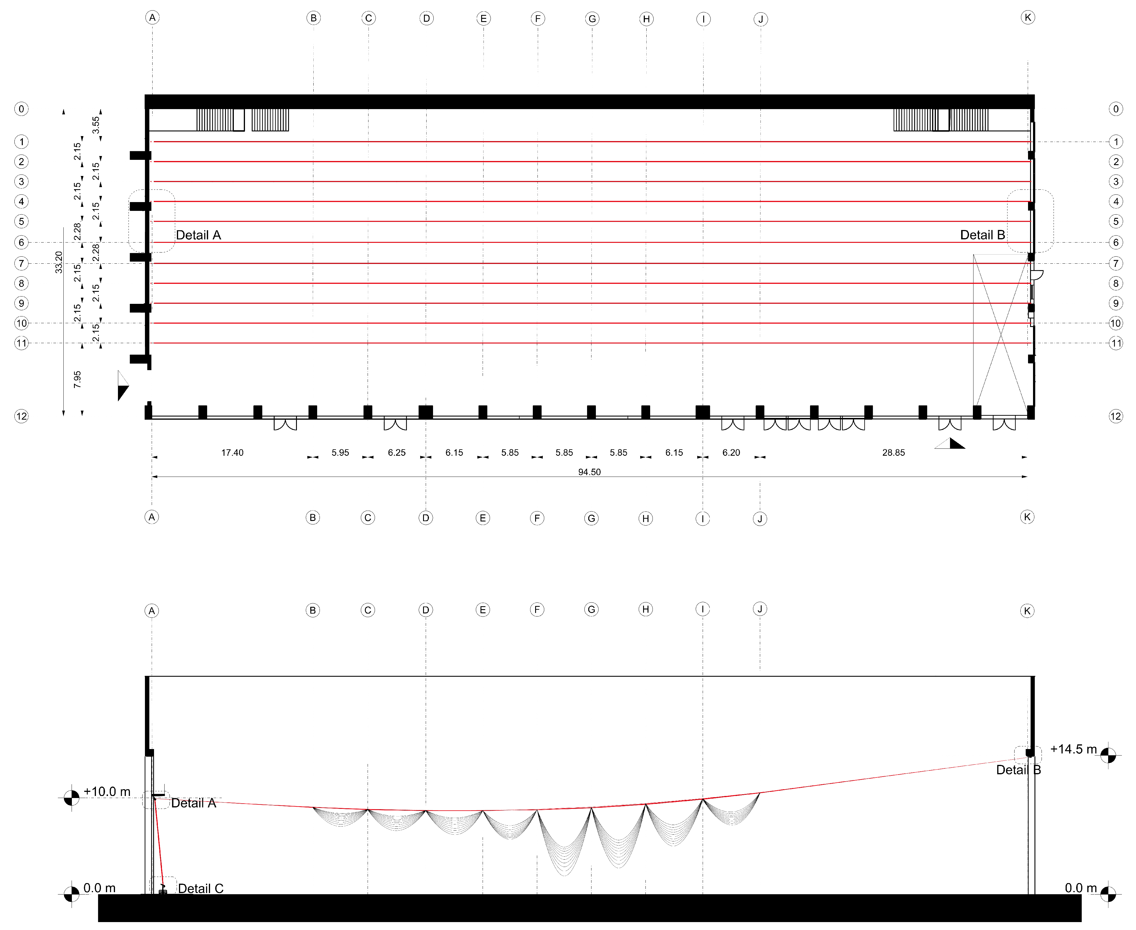
Figure 8a). However, the presence of windows heavily limited the freedom in choosing locations for the hanging structure’s anchor points. Moreover, because of the inevitable sagging of the cable when spanning, it was difficult to maintain the same height for fabric strips that belong to the same row. This would have called for the need to add a second array of cables in addition to the main one, which would have significantly affected the simplicity and abstraction of the overall form. Therefore, we ultimately decided to suspend the fabrics along the building’s longitudinal axis (
Figure 8b,
Figure 9 and
Figure 10). This decision results in four direct benefits:
It provides more freedom in the placement of anchor points on the walls;
The anchor points of each cable are placed further away one from each other, thus evoking a sense of ambiguity due to The Canopy’s incomprehensible structural logic as users cannot see both arrays of anchor points simultaneously;
The cables span the entire 94.5-m-long hall, elongating The Canopy longitudinally, expanding the covered area, and enhancing the dialogue with the building;
The longitudinal anchorage allows the lower portion of the fabric to remain horizontal in the vertical direction while slightly lifting the sides due to its own sagging, giving the sides of the building a geometry that follows the interior circulation more closely.
4.1.1. Form-Finding through Graphic Statics
After the definition of the hanging direction, graphic statics was used to investigate the geometry of the cables that would support the fabric strips, as well as to control the forces in the supports.
The Canopy’s catenary line is not just a formal translation of the form diagram of graphic statics. Instead, it is an attempt to retrace the design logic of graphic statics as a method and integrate it with the site and functional needs of the conference. Therefore, the interaction and synergy between the force diagram and the form diagram were used in many ways as the leading logic in designing the structures of
The Canopy. The use of graphic statics allows for a clear illustration of the relationship between form and forces to control the relationship between the height of each fabric strip, as well as their length.
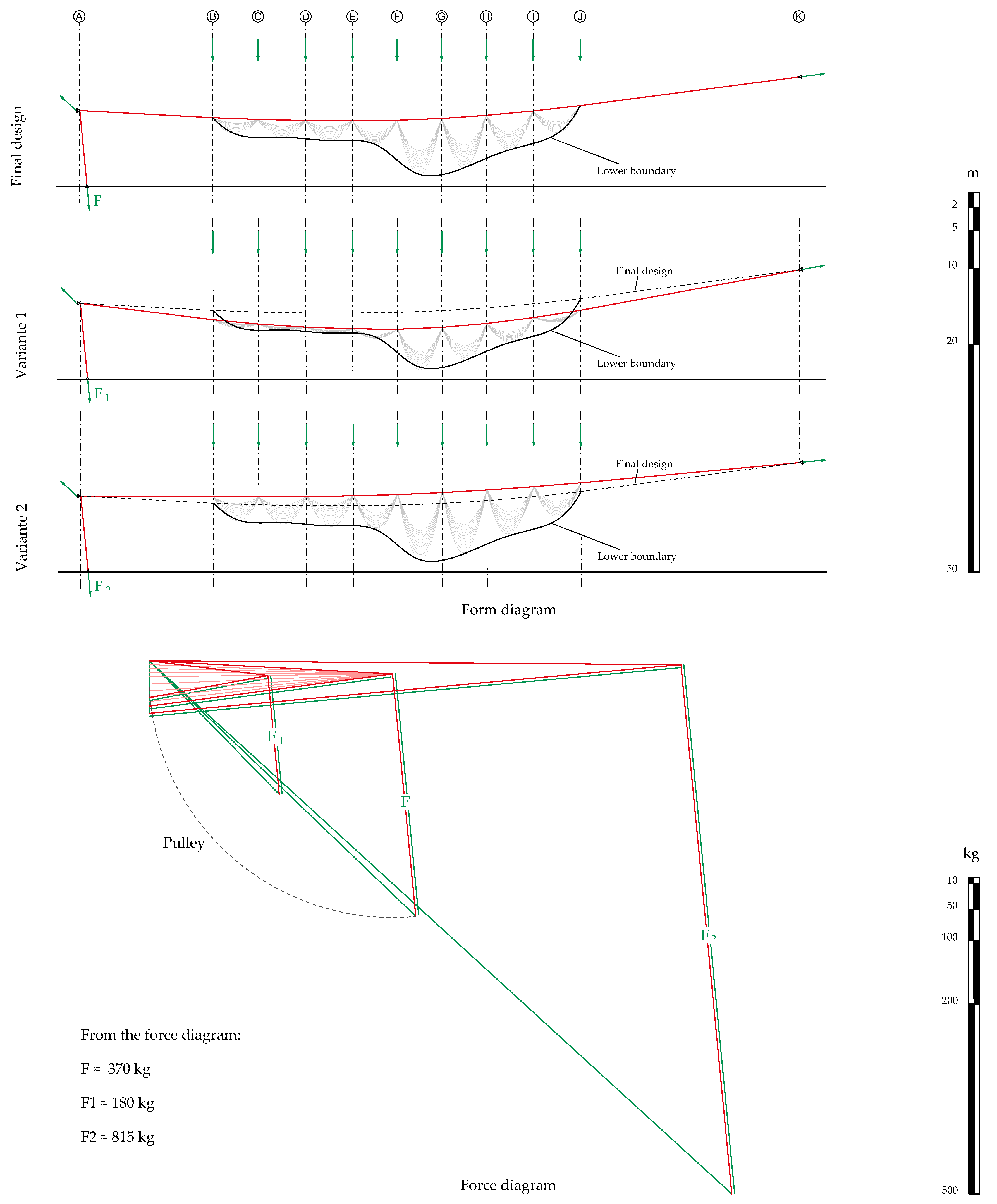
Figure 11 shows the final geometry, as well as two variants with a slightly lower (Variante 1) and higher (Variante 2) cable. The corresponding force diagrams show the change of the force F in the cable connected to the counterweight according to the three different geometries. It is worth mentioning how the force in the cable is extremely sensitive to changes in cable height and vice-versa. Thanks to the use of graphic statics, this dependency between design parameters (i.e., depth of the cable sag, force in the cable, and reaction forces) is represented in an explicit manner. The manipulation of form and force diagrams represented an extremely important design tool that allowed controlling the form of the cable and the resulting forces in the walls jointly. The geometric lower boundary of the installation is determined by the separation function that the fabric needs to provide. The final design is, therefore, a tradeoff that enhances the expressiveness of the canopy and its functional aspects, while keeping the forces under control.
Because of the undulating form, the weight distribution at each point where the fabric and the cable are connected were different. The magnitude of the force at each connection point informed the geometry of the cable and, consequently, the relative height between each strip and the adjacent strip of the fabric. This necessarily results in an iterative form-finding process in which the shape of the fabric and the cable are interdependent. Thanks to the use of parametric tools (i.e., Grasshopper3D), it was possible to instantly update the relative relationship between the form of the fabric and the force on the cable, as well as provide immediate feedback on the magnitude of the force and the corresponding form. As a result, the folding positions of the ten fabrics waves corresponded to the positions of the concrete trusses on the roof, and the precise control of the forces enabled the structural elements to be as thin as possible, thus enhancing the dialogue between The Canopy and the existing structure.
Due to production and transportation constraints, the longest dimension of a fabric roll was limited to 75 m. Therefore, we implemented a simple optimization algorithm to approximate as closely as possible the relationship between the desired undulating form and the total length of the fabric, in the attempt to minimize the need for cuts and overall material waste. This optimization problem was solved using Galapagos [
32], a native Grasshopper3D component.
4.1.2. Structural Detailing
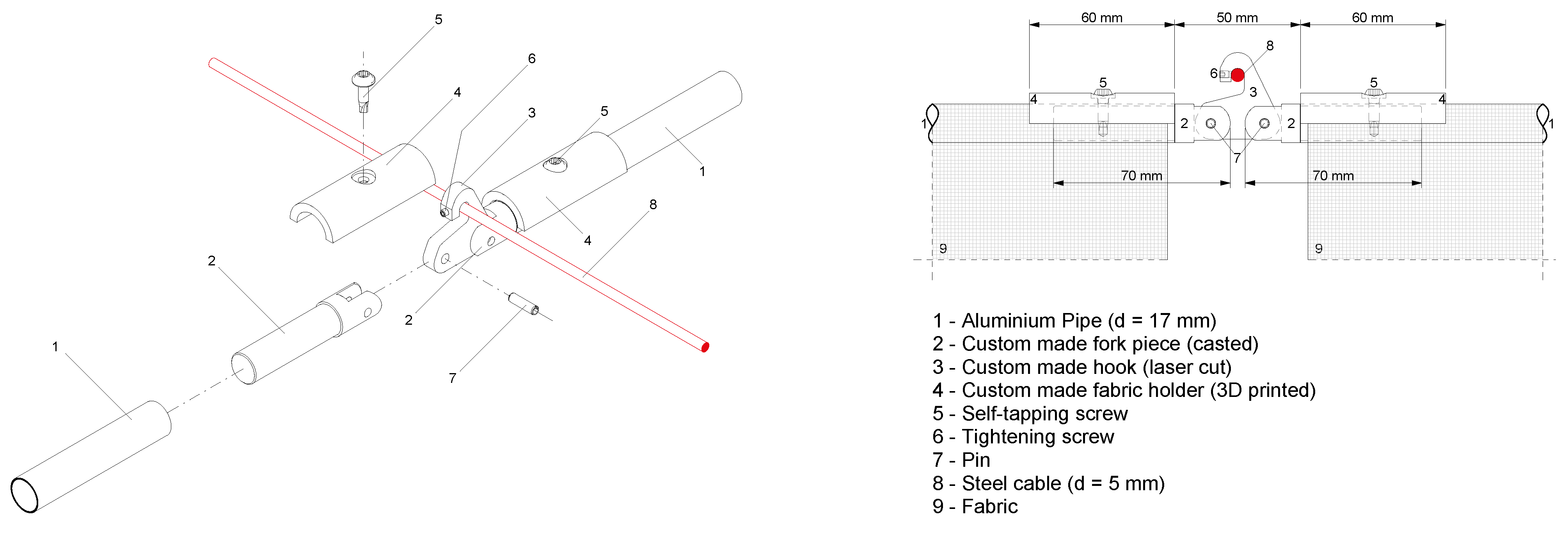
Once the overall force distribution pattern was determined, it was necessary to develop a connection system between extremely thin steel cables (⌀ 5 mm) and aluminum pipes (⌀ 17 mm) on which the fabric is folded. The system had to be easy to produce and it had to allow for simple adjustments on site also considering that neighboring pipes might result in misalignments along the vertical direction. For this reason, the joint between the cable and the pipes was designed as a hook that is pin-jointed to the pipes in order to guarantee the necessary tolerances with respect to vertical movements. The connection between fabric strips and pipes was solved using 3D printed holders to be screwed directly onto the pipe (
Figure 12 and
Figure 13). To meet the constraints of a three-day construction period and a one-day dismantling period,
The Canopy was designed in such a way that all the components could be pre-fabricated and partially pre-assembled in the workshop. The following section illustrates the pre-fabrication process and how the assembly was then carried out on site.
4.2. Construction: A Convenient and Flexible System
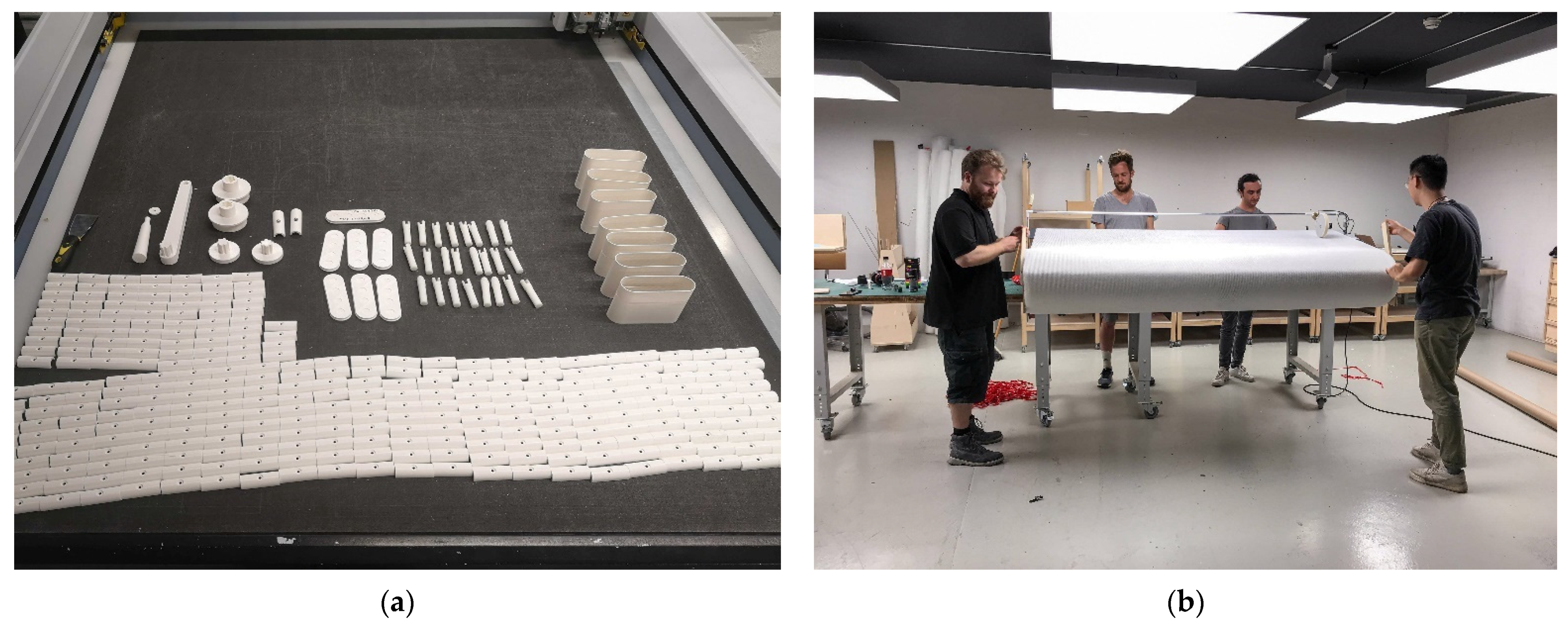
The Canopy’s entire structure was pre-fabricated at ETH Zurich and partially assembled before transporting it to the site. The components of the nodes were custom made-using 3D printing and laser cutting, and pre-assembled onto the pipes (
Figure 14a). This made it possible to quickly hang and adjust them on-site during construction. To ensure that the fabric folding position could be precisely measured and that the aluminum pipes could be fastened without creating creases or discoloration of the fabric from repeated fabrication processes, a customized rolling machine was developed at the Raplab at ETH (
Figure 14b). This allowed for precise measurements of the fabric strips and for an easy installation of the pipes at the right location along the strips.
Eventually, the 10 fabric rolls—with pipes already installed on them—were transported on site. At that point, 11 pairs of anchor points were installed on both walls. Due to the structure’s extreme lightness, the anchor points for the cable consisted of 22 mm threaded bars and stainless steel rings. The 22 anchor points represent the sole direct intervention on the existing structure.
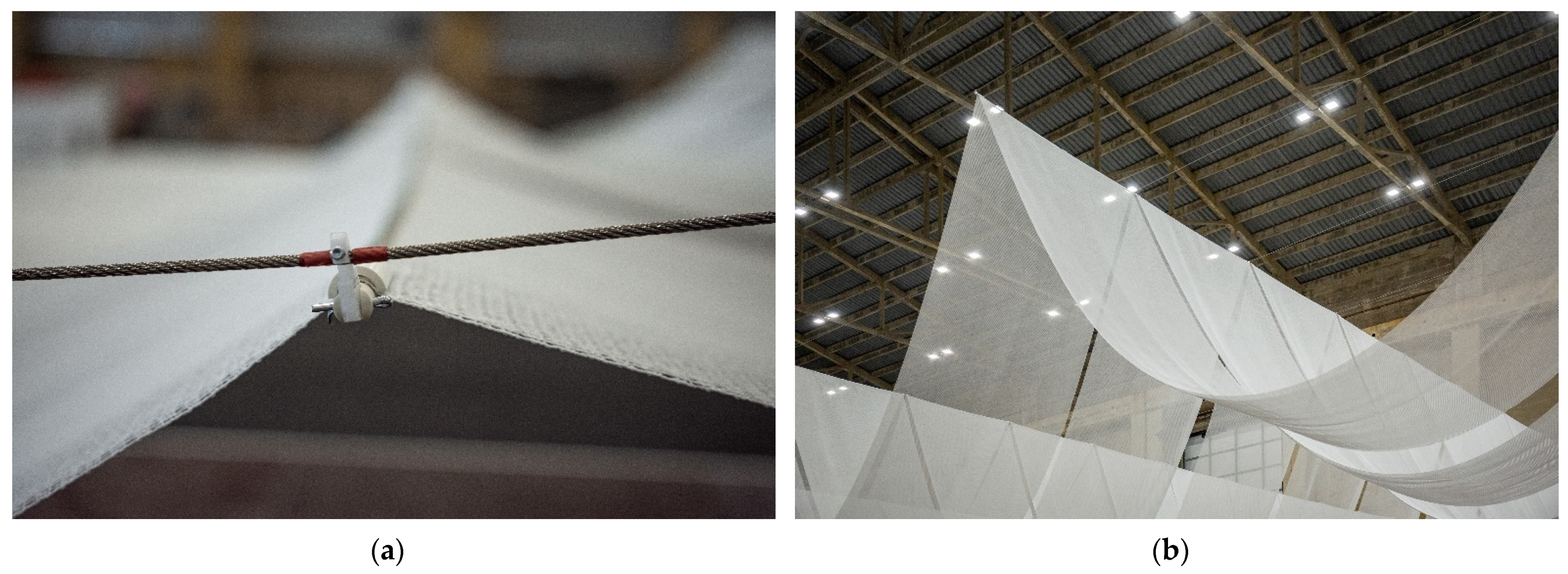
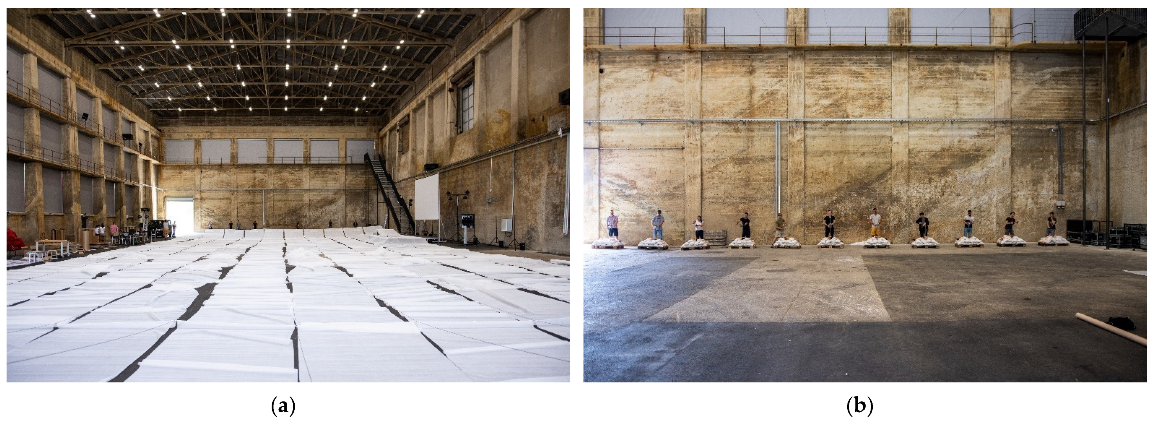
The stainless steel cables were connected on one end directly to the anchor points on the wall, whereas the other end is redirected to a set of counterweights placed on the ground using a pulley. The counterweights were created on site using sandbags. To facilitate the assembly process, the counterweights were equipped with a hand-operable winch to control the length of the cables, and thus their height above ground. Once the cables were arranged, the 10 fabric strips were unrolled on the ground and connected to the cables using the hooks (
Figure 15a). The erection process consisted of a simultaneous rise of the 11 cables until they reached their final position (
Figure 15b). The overall erection process was carried out in less than two days, whereas the final disassembly required only three hours, including the process of rerolling the fabric for future reuse.
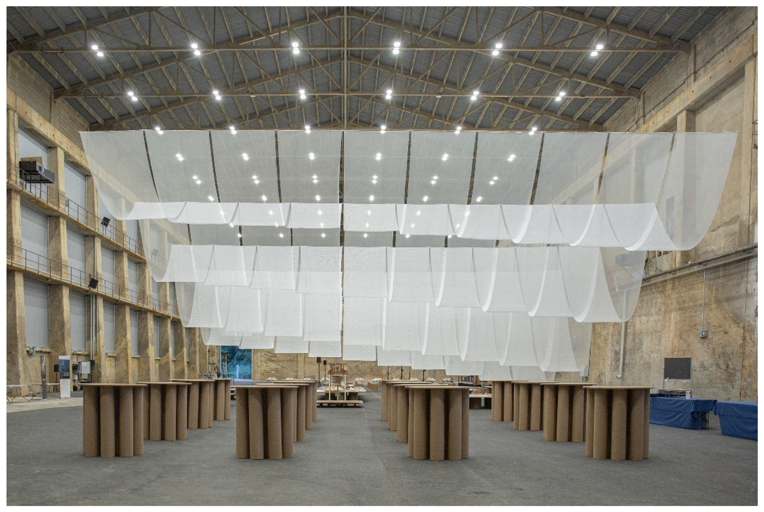
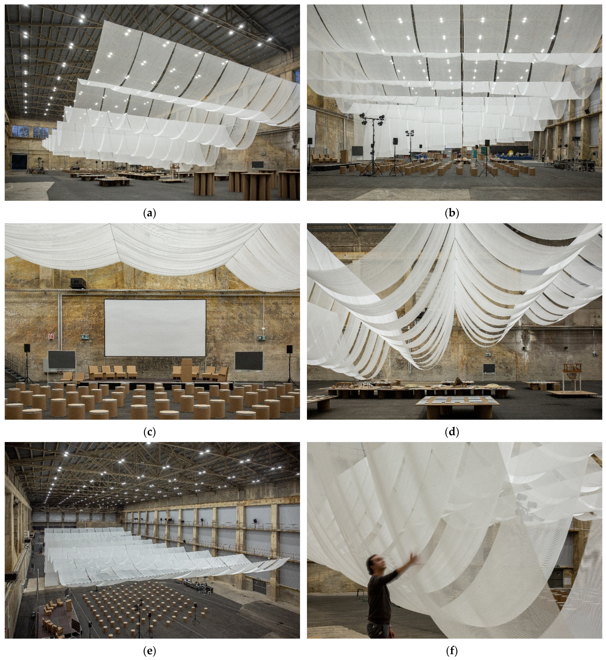
4.3. Tectonic: An Abstract Floating Cloud
Due to the in-depth consideration of the structure, the final expression of
The Canopy appears as a temporary cloud floating in the
Kiesofenhalle in a pure and ethereal way, showing ever-changing levels of transparency as the user moves in the space. The user’s perception is challenged, as the structural logic is not evident at first glance. This was achieved thanks to the extremely thin cables that almost disappeared in the height of the hall. This ambiguous structural expression also invites users to discover and explore the entire installation from all sides, inadvertently echoing the conference’s intention to refine and stimulate conceptual thinking about structures through a multidisciplinary exchange. Furthermore, the long side of
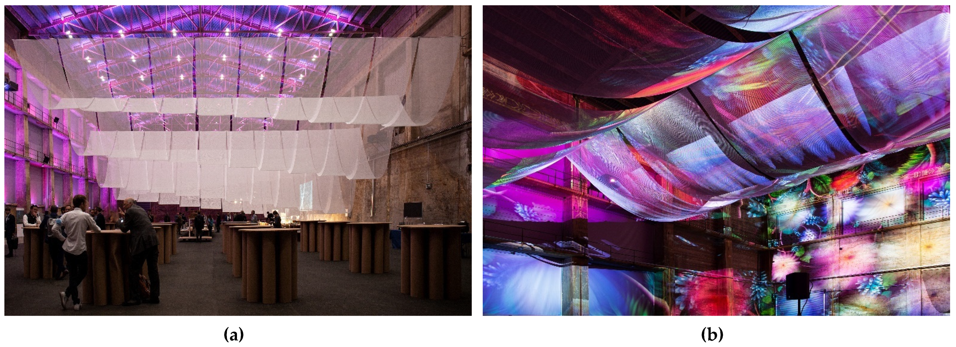
The Canopy, with its gaps between the fabrics, exposes as much as possible of the original walls, thus defining the scale of the space primarily in terms of height. This enhanced the existing architectural quality of the space and gave it new life subtly and reverently, swiftly transforming it into a new functional space (
Figure 16). Interestingly, the
Kiesofenhalle is also used for cultural events and exhibitions, and it featured an indoor immersive light show that was displayed at the end of the conference (
Figure 17). Although it was not considered in the design process, such a unique lighting condition greatly enhanced the floating image of
The Canopy.
5. Discussion
The final materialization of
The Canopy demonstrated that all the design intentions, functional requirements, and site constraints were met. The thinking process behind this project reflects the interaction between form and force, creating a space of “Strong Structures” [
33] through a synergy of structure, construction, and tectonic aspects with an extremely lightweight and minimal intervention.
The Canopy ultimately succeeded in providing an attractively proportioned and functionally partitioned temporary space for the conference, always respecting the existing space in which it was immersed. By considering the structure from multiple scales and perspectives, the design concept and the intended function of the space are achieved.
The use graphic statics enabled simultaneous control of form and forces during each design phase, and helped to reconcile structural constraints, functionality, and spatial expression of the factory building. The development of the form and force diagrams in 2D, as in the case of The Canopy, is in fact very simple to the point that it can also be conducted by hand. However, the development of a 3D structure soon results in more demanding graphical constructions as the geometric complexity significantly increases. This might represent the sole limitation of the method proposed in this paper, meaning that three-dimensional applications are often possible only with the help of 3D modelling software or specific digital implementations.
Finally, the workflow of
The Canopy shows that the pursuit of structural art is not about letting the structure’s sound overshadow the building itself [
34]. We can instead find an interdependent and solid balance between the two by utilizing the proper design medium and process [
35,
36]. Obviously, achieving this equilibrium requires multiple iterations of the design process instead of allowing the structure to realize the building’s form in a “post-rationalization” manner.
6. Conclusions
This paper described the design, fabrication, and erection process of The Canopy, a temporary spatial installation created as part of the International fib Symposium on “Conceptual Design of Structures”. The Canopy is the result of a multidisciplinary design process in which spatial, structural, and functional needs were reconciled using graphic statics. The diagrammatic and intuitive nature of graphic statics enabled the rapid communication and definition of structural concepts using both qualitative hand-sketches in the conceptual design phase and digital implementations of the method in the form-finding stage. The diagrammatic and cross-scale nature of graphic statics also clarifies the subsequent detail processing and construction process, enabling the structural concept to be systematically linked to the construction, thereby harmonizing the relationship between structure, construction, and tectonic in the design and reinforcing their relevance. The design process of The Canopy demonstrates the significance of collaboration and the use of common and practical design methods in structural design such as graphic statics. In fact, without the establishment of an effective common ground between architects and structural engineers The Canopy’s final spatial expression would not have been possible.
At the end of the conference, the company currently managing the Kiesofenhalle expressed the desire to preserve The Canopy and reuse it for future events. The Canopy is currently stored in the warehouse adjacent to the hall and will be re-erected in the hall to recreate, with extremely simple means, that space-within-a-space that allowed a radical, yet respectful transformation of the Kiesofenhalle.


