Article

Investigation of the Thermal Performance of Lightweight Assembled Exterior Wall Panel (LAEWP) with Stud Connections

1
Department of Civil Engineering, Xi’an Jiaotong-Liverpool University, 111 Ren’ai Road, Suzhou 215123, China
2
Institute for Sustainable Materials and Environment, Xi’an Jiaotong-Liverpool University, 111 Ren’ai Road, Suzhou 215123, China
3
Shanghai Jun Dao Residential Industry Co., Ltd., 438 Jinwei Road, Baoshan District, Shanghai 201901, China
*
Author to whom correspondence should be addressed.
Buildings 2022, 12(4), 473; https://doi.org/10.3390/buildings12040473
Submission received: 9 March 2022 / Revised: 1 April 2022 / Accepted: 7 April 2022 / Published: 12 April 2022
(This article belongs to the Topic Energy Efficiency, Environment and Health)

Abstract

:
One of the most effective ways to improve building energy efficiency and consumption is to increase the thermal insulation of the building envelope and reduce the heat loss through walls. A new type of thermal insulation wall panel, consisting of a lightweight assembled exterior wall panel, was investigated in this research through experimental and numerical analyses. The feasibility of achieving the anticipated thermal performance through finite element modeling using ABAQUS® was verified. Good agreement between numerical simulation and experimental measurement was found, and the accuracy is 98.8%. To further reduce the heat transfer coefficient (U-value) of the panel to improve its thermal performance, parametric analyses were conducted utilizing the validated finite element model. The simulation shows that changing the insulation material is the best option, and the U-value reduction percentage reached 13.2%. Moreover, the combination of reducing the number of steel studs, decreasing the size of steel studs, implementing the opening of the light-gauge steel, and improving the insulation material led to a 23.7% reduction in the U-value at 0.695 W·m−2·K−1.

1. Introduction

Enhancement of energy efficiency in the construction industry has become China’s national priority [1] due to the increased weighting of building energy consumption in the past decades [2,3,4]. To achieve sustainable development goals, building energy conservation shall be achieved through the improvement of building design, construction, and usage. The exterior wall is one of the main components of a building, and its structure and materials directly affect the building’s energy consumption. It has been estimated that 34% of the energy consumption of residential buildings is attributed to the exterior walls [5]. Therefore, to improve building energy efficiency and reduce energy consumption, the most effective way is to increase the thermal performance of the exterior building walls to reduce heat loss [6]. Lightweight assembled exterior wall panel (LAEWP), a new type of lightweight thermal insulation wall, usually consists of light-gauge steel, exterior slabs such as stone soundboard or oriented strand board, and interior insulation materials such as rock wool or thermal insulation mortar. Usually, the light-gauge steel frames serve as the main structural component. LAEWP is proposed to accelerate construction by reducing onsite work and was proved to be structurally sound [5]. However, its thermal performance is in doubt due to the light-gauge steel frame and steel studs as connectors.
Light-gauge steel has great mechanical properties, high strength, secure processing, and better connection. For the reason that the thermal conductivity of light-gauge steel is around 50 W·m−1·K−1, which is much higher than that of thermal insulation material (thermal conductivity of rock wool is usually less than 0.05 W·m−1·K−1), the thermal bridge will form and thus dramatically increase building energy consumption [7,8]. Condensation due to temperature differences will cause mildew and dripping off the wall, which would also deteriorate the thermal insulation performance of the insulation material and affect the everyday use of the wall panels. Therefore, thermal performance is a crucial factor for the implementation of LAEWP in addition to structural requirements.
In recent years, numerous studies have been focused on the thermal insulation performance of the assembled wall. Gorrell stated that condensation is the major problem in prefabricated composite building walls [9]. The main reasons identified were, for example, exfiltration of warm, moist indoor air, water vapor diffusion, and inadequate separation and/or insulation [9]. Fantozzi et al. conducted a detailed analysis and discussion on the dynamic thermal performance of the lightweight wall. They found that the thermal insulation performance of prefabricated exterior wall panels can be significantly improved through the lumped parameter method [10]. By comparing the conventional plate, Song et al. adopted the heat insulation bracket and improved aluminum die to reduce the phenomenon of the thermal bridge on the thermal performance of the metal curtain wall system [8]. Bamonte et al. analyzed the influence of the thermal performance of the wall panel with phase change material using the finite element method (FEM), and the wall panels with phase change materials led to a 20% reduction in the energy required for the indoor physical environment in the hot season [11]. Pekdogan and Basaran pointed out that more heat loss can be decreased in different climates and directions by adding the thermal insulation of the sandwich wall. The heat loss can also be dramatically reduced by 65% [12]. Hachim and Abed introduced a new design method of a sandwich wallboard designed by adding layers of insulation material to the wall, which can effectively save electricity [13].
Chu et al. analyzed the condensation problem of precast concrete sandwich insulation exterior wall panels and they found that all types of precast concrete sandwich insulation wall panels have condensation inside though the area was small [14]. Pan et al. used the infrared thermal imaging method to test the exterior envelope structure of the assembled building. The results showed that the defect of the envelope structure of the assembled building is more minor, which is beneficial for the building energy saving [15]. Bu et al. investigated the thermal insulation performance of the expanded polystyrene (EPS) modular shear wall structure system, and it was found that the insulation layer thickness on both sides of the EPS module system is 60 mm and the heat transfer coefficient is only 0.27 W·m−2·K−1, which shows that the system has excellent thermal insulation performance [16]. Li et al. analyzed the thermal insulation performance of sandwich ventilation walls. Compared with the heat transfer coefficient with a non-thermal insulation cover, the thermal insulation performance of the sandwich wall can be further improved by 12.3% [17]. Wang et al. stated that the polystyrene particle insulation mortar could adequately compensate for the shortcomings of the high thermal conductivity of steel bars and effectively reduce the thermal bridge effect and maintain the indoor temperature stability [18]. To decrease the heat transfer coefficient of the wall, Jin et al. put forward a reasonable web openings parameter and spacing, which provided design suggestions for engineering practice [19]. According to the simulation results presented by Li et al., it was found that when the number of web openings is five, the proportion of web opening is 50%, the height of the keel cross section is 200 mm, and more layers of gypsum board are added, the thermal insulation effect is better [20].
The LAEWP investigated in this research utilized a new type of high-strength concrete to reduce the thickness of the exterior concrete layer and, therefore, the self-weight of the pane was decreased. The decrease in panel weight will reduce the transportation cost and simplify the installation process. Although the panel is structurally adequate, the thermal performance is affected by adopting a 50 mm thick exterior concrete layer and steel head studs connecting the concrete slab and supporting light-gauge steel. The primary focus of the research was to determine an improved insulation solution for the proposed LAEWP, for which a combined approach will be presented.

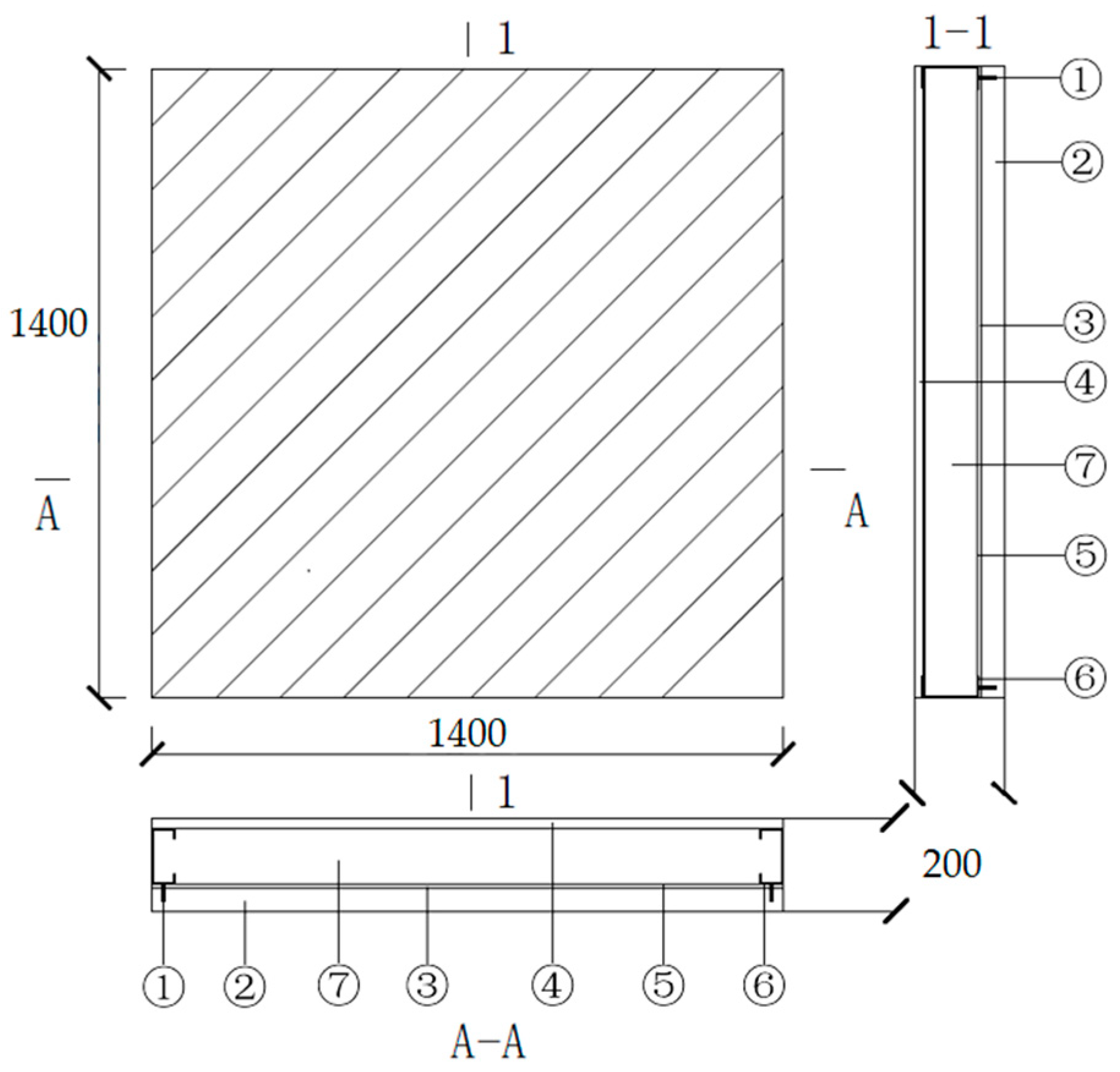
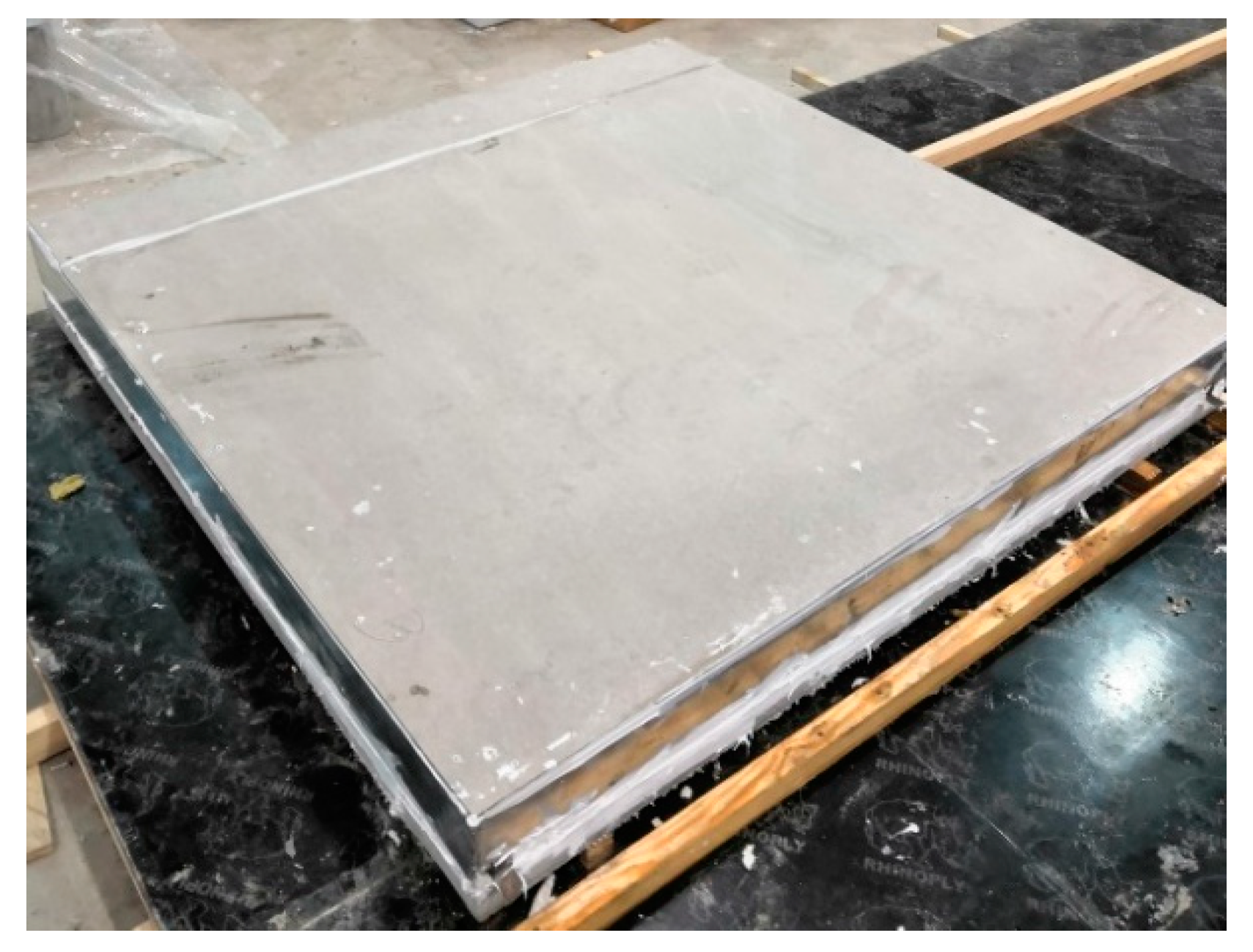
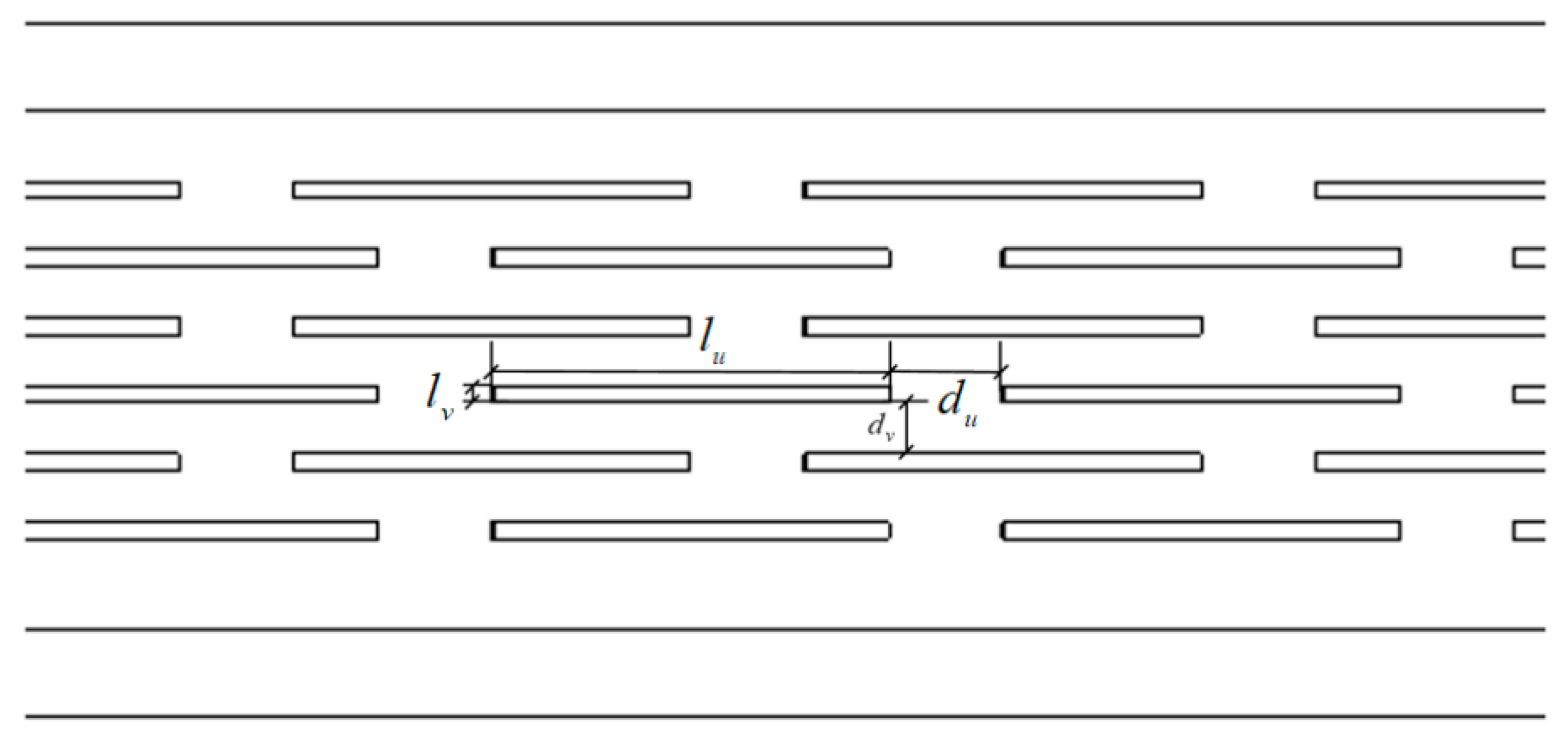
2. LAEWP Configuration

The configuration of the proposed LAEWP can be seen in Figure 1. The overall dimension of the panel is 1400 mm × 1400 mm × 200 mm and includes seven components, as shown in the figure legends. The dimensions are consistent with the thermal performance experiment, while the stud and light-gauge steel frame configuration is equivalent to the full-size panel. The exterior layer adopted high-strength concrete with compressive strength of over 140 MPa. The concrete layer was connected to the light-gauge steel by steel-headed studs whose diameter and length are 10 mm and 40 mm, respectively. A 10 mm thick air layer was maintained between the concrete and light-gauge steel by adjusting the embedment depth of the steel studs. Two types of light-gauge steel members, namely, the C-shape and U-shape, were used in the panel. The dimension of the C-shape and U-shape light-gauge steel members are 120 mm × 50 mm × 15 mm × 2 mm and 120 mm × 50 mm × 2 mm, respectively. The whole thickness of high-strength concrete is 50 mm. The 20 mm thick fibrous concrete board was utilized as the back panel, while sprayed EPS insulation material or polystyrene particle mortar with 120 mm thickness was used to fill the space between the front and back concrete panel and the space between the light-gauge steel frames. The fully prepared LAEWP specimen is shown in Figure 2.

3. Thermal Performance Testing

The heat transfer coefficient of the LAEWP was measured according to BS EN ISO 8990:1996 [21] by a certified third party testing service provider. The heat flow due to moisture transfer or redistribution was prevented in the experiment by controlling the moisture in the testing environment and maintaining an initial dry condition of the specimen. The measured heat transfer coefficient for the two panels with polystyrene particle mortar and EPS foam are shown in Table 1. The heat transfer coefficient of the panel with EPS foam (0.9 W·m−2·K−1) was smaller than that of the panel with polystyrene particle mortar (1.15 W·m−2·K−1). Because the experiment is expensive and time-consuming, numerical simulation was adopted to assess the various improvement approaches and further optimization.

4. Thermal Performance Simulation

4.1. Method Verification

Thermal simulation results from previous research [22] were used to verify the simulation method used in the paper. It is stated that the steady-state heat transfer of the wall can be approximated as a one-dimensional steady-state heat transfer problem [23]. Therefore, a 3D model was created in ABAQUS® using 3D BH240 elements to simulate the masonry unit. The XY plane geometric dimensions of the new 3D BH240 model were acquired based on the geometry of 2D BH240 model in reference [22] and the length of the model in the Z direction is set as 190 mm, where the thickness of the air layer is 40 mm. All the boundary conditions, thermal conductivity of different materials, and simulation parameters of the new 3D BH240 model were obtained according to reference [22]. The third boundary condition of the steady-state heat conduction was used as the boundary condition of finite element analysis. Furthermore, a tie constraint was used for all contacts between components. The thermal conductivity of different materials and air interlayers in the FEM model are shown in Table 2. The indoor and outdoor ambient temperatures and surface conditions were obtained as shown in Table 3.
Through steady-state heat transfer analyses in ABAQUS®, the maximum and minimum temperature values of the hot and cold sides of the model were 15.050 °C and 0.953 °C, respectively. The maximum and minimum heat flux values of the model were 114.50 W·m−2 and 6.20 W·m−2, respectively. The temperature distribution and heat flux distribution of the 3D model were similar to those in the literature, as shown in Figure 3a.
The heat transfer coefficient equals the heat of the unit area of the wall in a unit time when the temperature difference between the two sides of the wall is 1 °C. In the steady-state heat transfer process, the total heat flux of each layer of heat transfer surface in the vertical direction is equal. Therefore, the heat transfer coefficient of the wall can be calculated by the average temperature difference between the two sides of the wall and the average heat flux density of any section perpendicular to the heat flow direction. The calculation formula is shown in Equation (1):
K = q Δ T
q is the average heat flux of the heat transfer layer in the vertical direction of heat flow; Δ T is the average temperature difference on both sides of the wall. Based on the results of ABAQUS®, the average temperature difference is 14.097 K, so the heat transfer coefficient of the model can be obtained only by knowing the average heat flux. Because the heat flux distribution is the same along the thickness direction in any section perpendicular to the heat flow direction. The heat flow distribution on the section can be represented by any heat flow distribution path along the Y direction. Therefore, two different paths were created in the model, and then heat flux data of all nodes can be obtained in each path. Therefore, the average heat flux can be calculated through the average left and right heat flux values. Each path and the heat flux of each node can be shown in Figure 3 and Figure 4.
The average heat flux values of the left and the right path in the 3D model are 31.25 W·m−2 and 32.09 W·m−2, respectively, so the average surface heat flux is 31.67 W·m−2. Therefore, the heat transfer coefficient between the FEM model and the reference can be shown in Table 4, and the difference is only 1.5%. Thus, the method for obtaining the heat transfer coefficient was verified based on the 3D BH240 model and will be used to calculate the heat transfer coefficient.

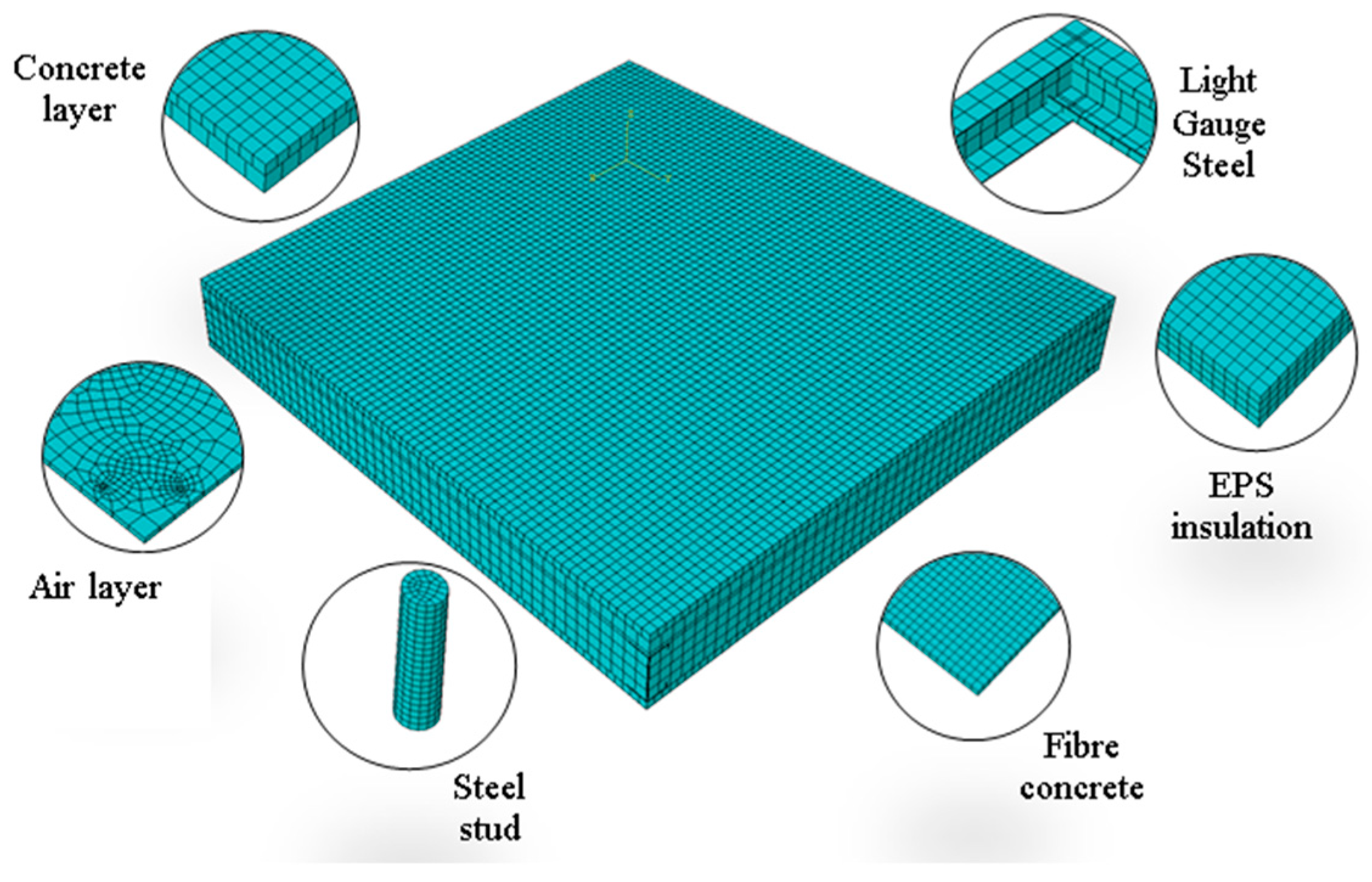
4.2. FEM Model of the LAEWP

The FEM models of the LAEWP and each component are shown in Figure 5. All elements were considered as homogeneous solids, and the element type selected was the DC3D8 linear thermal analysis element. In practice, because light-gauge steel and concrete are connected by studs, it is necessary to accurately simulate the stud holes in concrete in the ABAQUS® modeling process. Due to the occurrence of an air layer in the actual model, the heat flow cannot be transferred typically if the air layer model is not established in ABAQUS®. Therefore, it is necessary to establish the air layer according to the arrangement of studs.

4.3. Material Property

The thermal conductivity of concrete is estimated to be 1.62 W·m−1·K−1 [24]. According to EN ISO 6946: 2017 [25], when the thickness of the air layer d was 10 mm, the thermal resistance R T equals 0.15 m−2·K−1·W−1. Therefore, the thermal conductivity of the air layer λ can be calculated using Equation (2), which equals 0.067 W·m−1·K−1.
R T = d λ
Based on the results obtained from the literature, the thermal conductivity of the EPS insulation material and light-gauge steel were 0.036 W·m−1·K−1 and 50 W·m−1·K−1, respectively [26]. The thermal properties of the steel stud were the same as that of light-gauge steel. As per GB 50176-2016 [27], the thermal conductivity of fiber concrete was 0.85 W·m−1·K−1. The thermal conductivity of different materials adopted for the LAEWP is summarized in Table 5.

4.4. Boundary Conditions

The external and internal temperatures were set equal to −20 °C and 20 °C, respectively. According to EN ISO 6946: 2017 [25], for horizontal heat flow, the convective surface heat transfer coefficient for the external and internal environment h e and h i can be set as 25 W·m−2·K−1 and equals 7.69 W·m−2·K−1, respectively. The tie constraint was used for all contacts between components, and steady-state heat transfer analyses were conducted based on heat conduction.

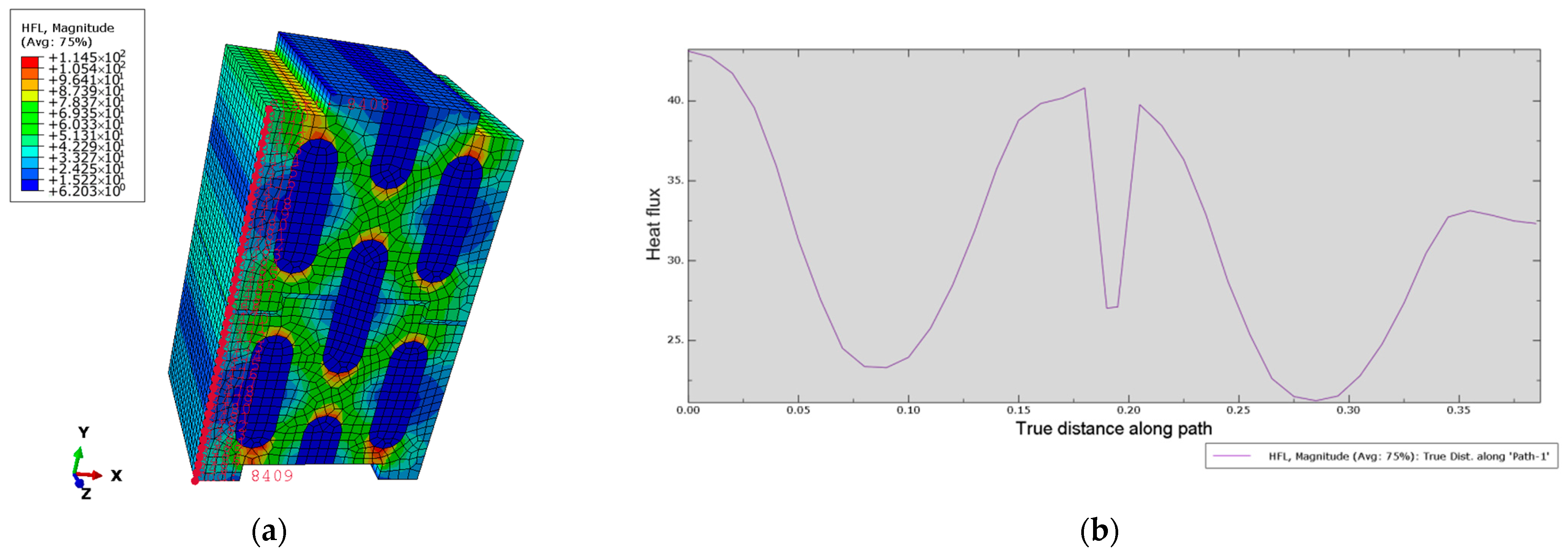
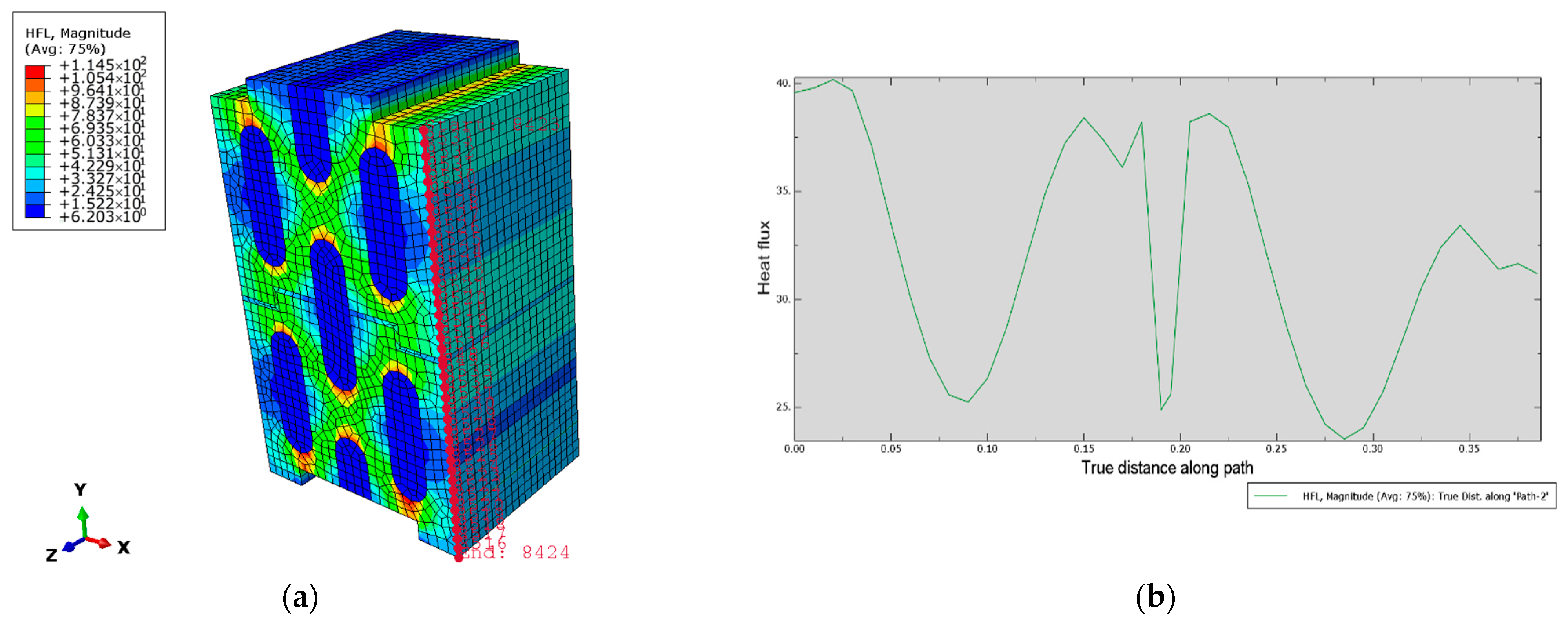
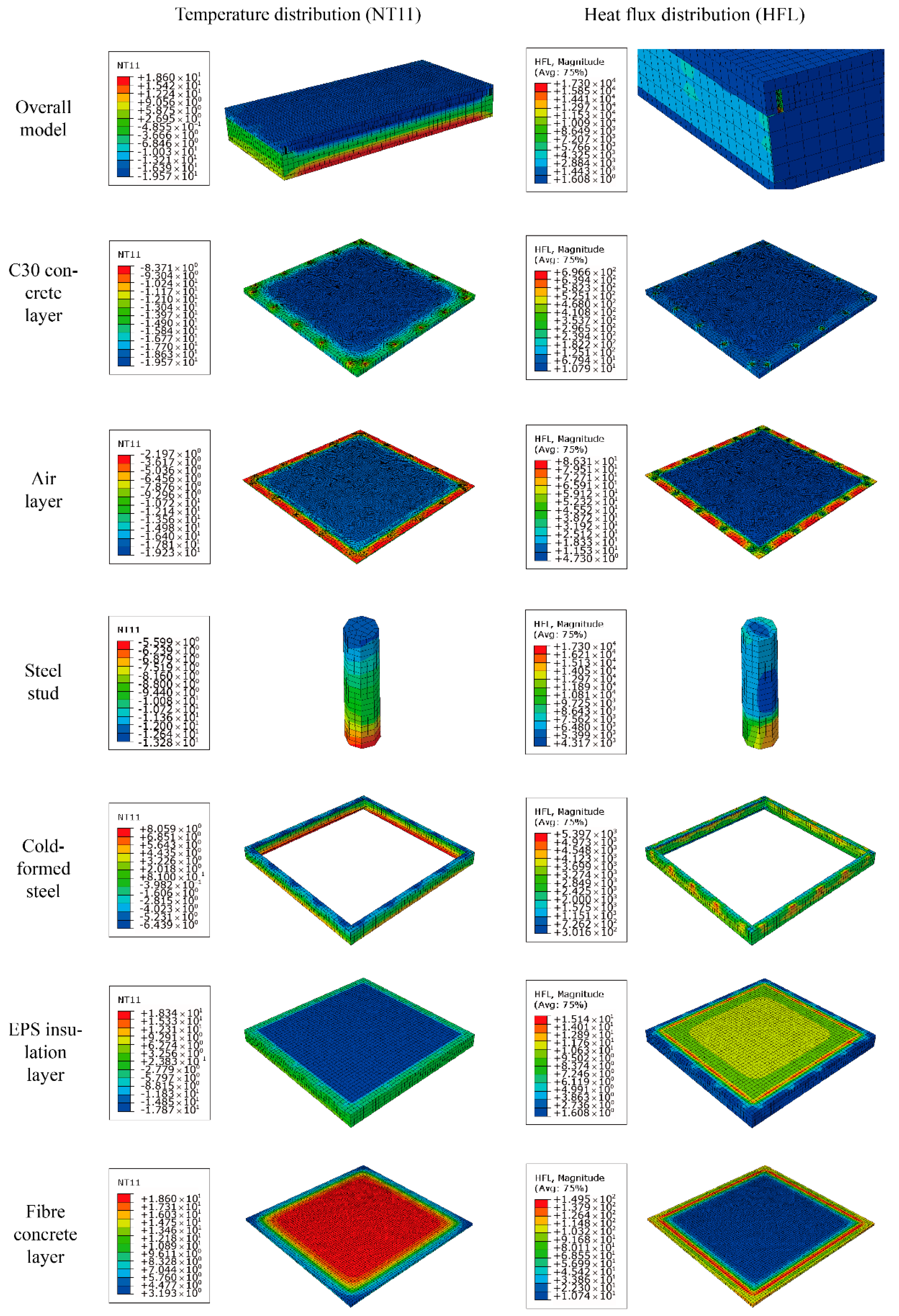
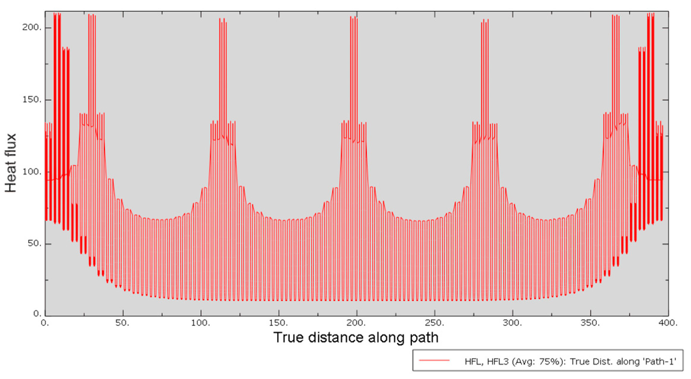
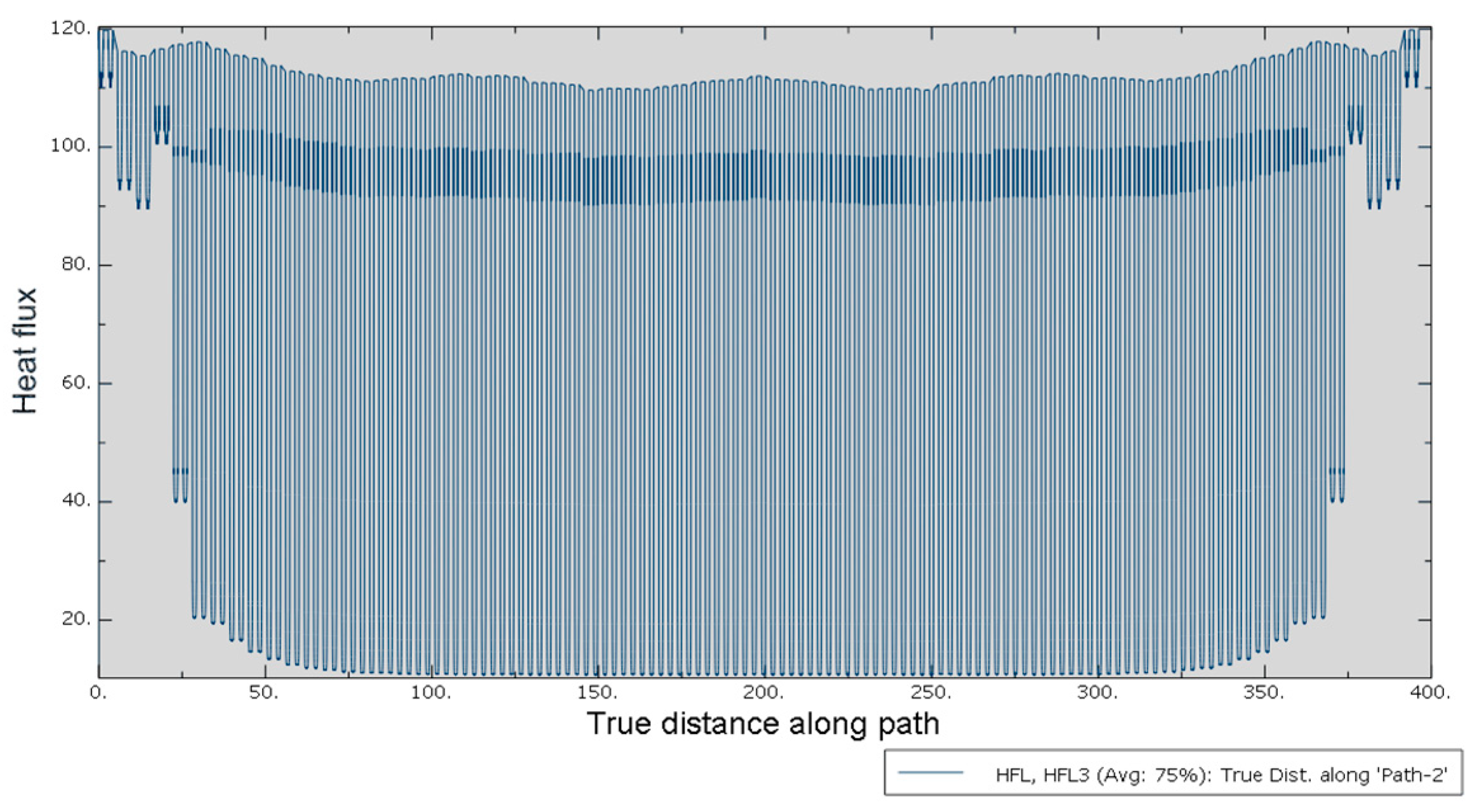
4.5. Results and Analysis

The distribution of temperature (NT11) and heat flux (HFL) of the LAEWP and different components are shown in Figure 6, and the extreme values of temperature and heat flux are summarized in Table 6. The maximum heat flow occurs at the connection between the steel stud and the light-gauge steel because the thermal conductivities of both materials are much higher than those of others, and there is a large amount of heat flow transfer when they are in contact. The minimum heat flow occurs around the EPS insulation layer because the thermal conductivity of EPS is the lowest, and a large amount of heat flow is transferred through the light-gauge steel.
According to Equation (1), to obtain the heat transfer coefficient of the LAEWP, the average heat flux q and the corresponding temperature difference Δ T need to be calculated. Because the total heat flow at any section perpendicular to the direction of heat flow is equal, the value of HFL3 will be taken as the actual heat flow rather than the HFL magnitude. The integration point algorithm will be numerically carried out to obtain the average heat flux in this process. Then, the average heat flux of concrete and fiber concrete were obtained from the numerical model as shown in Figure 7 and Figure 8, which equal 30.8465827 W·m−2 and 30.8465868 W·m−2, respectively. The temperature difference Δ T was also be calculated based on the average temperature of all nodes of concrete and fiber concrete, which equal −18.505 K and 15.373 K, respectively. With an average heat flux of 30.847 W·m−2 and a temperature difference of 33.878 K, the heat transfer coefficient of the LAEWP equals 0.911 W·m−2·K−1, which is in good agreement with the experimental result of 0.9 W·m−2·K−1 and the accuracy is 98.8%. The numerical result is sufficient to serve as the benchmark for further optimization work. The potential reasons for the overestimation can be inaccurate thermal conductivities and partial heat loss in the practical test. Furthermore, in the actual specimen construction process, due to the filling of EPS insulation materials, the thickness of the air layer may have decreased. However, in the numerical simulation model, an air layer of 10 mm was set, and the thermal conductivity of the air layer is almost twice that of EPS, which will also lead to an increase in the U value in the numerical simulation and have an impact on the insulation performance of the panel. Therefore, this is also an optimization factor that we need to consider in the later optimization process.

5. Improvement of the LAEWP

5.1. Univariate Improvement Approaches

To further improve the thermal performance of the LAEWP, several improvement approaches were proposed, such as reducing the stud size, reducing the stud number, application of web openings, and enhancing the thermal conductivity of various insulation materials. The effectiveness of several of those approaches was evaluated through the FEM model. Details of the models are explained, as shown in Table 7.
Web openings of light-gauge steel were introduced to extend the heat transfer path and decrease the equivalent thermal conductivity. The LAEWP is a non-bearing structure, so according to the reference [19,28], the dimension of the web openings can be 70 mm × 3 mm × 20 mm × 9 mm (length l u × height l v × horizontal spacing d u × vertical spacing d v ). The ratio of web opening is set as 50%, and the end distance of the web opening is recommended to be 0 mm, as shown in Figure 9.
The extreme values of temperature and heat flux of the LAEWP under different improvement scenarios are summarized in Table 8. All six improvement approaches have limited influence on the extreme temperature values of the LAEWP. Only three improvement approaches, SNR, TCL, and FWO, can reduce the thermal bridge effect of the LAEWP to some extent.
The heat transfer coefficient and the performance of different improvement methods can be obtained, as shown in Table 9. From the improvement approach labeled AAL, it was found that the final U value is decreased to 0.829 W·m−2·K−1 when the air layer was replaced entirely by EPS material. The final U value was smaller than the experimental result, 0.9 W·m−2·K−1, which also validates the estimation in Section 4.5. From Table 9, all six improvement approaches can reduce the heat transfer coefficient of the LAEWP and improve its thermal insulation performance. However, the first three (SSR, SNR, and TCL) have less impact when compared with the rest of the approaches (AAL, FWO, and IME). The minimal heat transfer coefficient of all six models is 0.791 W·m−2·K−1, which indicates that the improvement of the insulation material has the greatest impact on the insulation performance of the LAEWP.

5.2. Multivariate Improvement Approaches

As can be seen from the above, several univariate improvement approaches can effectively improve the insulation performance of the LAEWP to some extent. To further improve the thermal performance of the panel, the combination of several improvement approaches were investigated. The combination cases and results can be found in Table 10. From the point of view of optimizing cost and facilitating panel installation, the multivariate improvement approach labeled SSR + SNR + FWO was firstly carried out compared with other approaches because the labeled TCL will lead to the change of panel size and weight and bring construction difficulties. The labeled AAL and IME will lead to the increase in optimization cost, respectively. The result of the labeled SSR + SNR + FWO was below expectation, so the labeled AAL and IME can be respectively considered based on the result of the labeled SSR + SNR + FWO. All three multivariate improvement approaches can decrease the heat transfer coefficient of the LAEWP and better optimize the experimental result, where the approach labeled SSR + SNR + FWO + IME has been shown to give the best reduction percentage of the U-value by 23.7%. The heat transfer coefficient is 0.695 W·m−2·K−1.

6. Conclusions

To increase building energy efficiency, a new thermal insulation wall panel, consisting of a lightweight assembled exterior wall panel, was introduced to achieve sustainable development and decrease building energy consumption. Experimental and numerical analyses were carried out to study the thermal insulation performance of the LAEWP. The main conclusions can be summarized as follows:
  • The thermal insulation of the LAEWP with EPS foam (0.9 W·m−2·K−1) was found to have better performance than that of the LAEWP with polystyrene particle mortar (1.15 W·m−2·K−1);
  • The heat transfer coefficient of LAEWP found numerically was 0.911 W·m−2·K−1, which is in good agreement with the experimental result and the accuracy is 98.8%. Therefore, the FEM result is close enough to serve as the benchmark to evaluate the effectiveness of various improvement approaches. Reasonable overestimation of the heat transfer coefficient was also validated in the later improvement stage;
  • All six improvement approaches analyzed led to a reduction in the heat transfer coefficient of the LAEWP, ranging from 0.9% to 13.2%. The relative effectiveness methods are enhancement of insulation material and air layer, as well as the implementation of a web opening;
  • The multivariate improvement approach labeled SSR + SNR + FWO + IME was found to have the best insulation performance. The best reduction percentage of the U-value is 23.7%, and the heat transfer coefficient of LAEWP was recorded as 0.695 W·m−2·K−1.
The paper presents the 3D FEM simulation tool that was verified to be as effective and accurate as the 2D FEM model. The 3D simulation model on LAEWP was further validated through the comparison with experimental results. Thus, the effectiveness of various optimization methods can be preliminarily assessed. The proposed tool provides a novel investigation method for the future optimization of the panel, which saves the time and effort of repeating the physical tests. However, it shall be noted that the actual performance of the panel may also be subject to its working environment, for example, the indoor and outdoor moisture contents and the moisture content in the specimen itself. Although prior research concluded that change in humidity mainly affects the radiation between air layers and has little effect on heat conduction and convection for the composite wall [29], the thermal performance of LAEWP is worth further investigation, especially its performance in the actual application through onsite monitoring.

Author Contributions

Conceptualization, P.S.; methodology, P.S.; validation, J.X.; formal analysis, T.L.; investigation, T.L.; resources, P.S.; writing—original draft preparation, T.L.; writing—review and editing, J.X., C.S.C. and P.S.; visualization, T.L.; supervision, J.X. and C.S.C.; project administration, J.X.; funding acquisition, C.S.C. All authors have read and agreed to the published version of the manuscript.

Funding

The authors acknowledge the financial support from Xi’an Jiaotong-Liverpool University and Shanghai Jun Dao Residential Industry Co., Ltd. under Grant Number RDS10120170090.

Institutional Review Board Statement

Not applicable.

Informed Consent Statement

Not applicable.

Data Availability Statement

The data presented in this study are available on request from the corresponding author.

Conflicts of Interest

The authors declare no conflict of interest.

References

  1. Wang, J.; Li, L. Sustainable energy development scenario forecasting and energy saving policy analysis of China. Renew. Sustain. Energy Rev. 2016, 58, 718–724. [Google Scholar] [CrossRef]
  2. Nagy, B.; Stocker, G. Numerical Analysis of Thermal and Moisture Bridges in Insulation Filled Masonry Walls and Corner Joints. Period. Polytech. Civ. Eng. 2019, 63, 446–455. [Google Scholar] [CrossRef] [Green Version]
  3. Yüksek, I. The Evaluation of Building Materials in Terms of Energy Efficiency. Period. Polytech. Civ. Eng. 2015, 59, 45–58. [Google Scholar] [CrossRef] [Green Version]
  4. Zhang, Y.; He, C.-Q.; Tang, B.-J.; Wei, Y.-M. China’s energy consumption in the building sector: A life cycle approach. Energy Build. 2015, 94, 240–251. [Google Scholar] [CrossRef]
  5. Ye, Z. The Development Status and Trend of Prefabricated Composite Wallboard of Industrialization of Construction Industry. Fujian Constr. Sci. Technol. 2016, 1, 28–30. [Google Scholar] [CrossRef]
  6. Cao, S. New Technologies of Buildling Energy Efficiency in Contemporary. Sci. Technol. Inf. 2012, 15–16. [Google Scholar] [CrossRef]
  7. Song, J.-H.; Lim, J.-H.; Song, S.-Y. Evaluation of alternatives for reducing thermal bridges in metal panel curtain wall systems. Energy Build. 2016, 127, 138–158. [Google Scholar] [CrossRef]
  8. Song, J.-H.; Lim, J.-H.; Kim, Y.-I.; Song, S.-Y. Thermal Insulation Performance of Metal-exterior Curtain Wall Panel Systems with Thermal Bridges in Winter. Procedia Eng. 2016, 146, 8–16. [Google Scholar] [CrossRef] [Green Version]
  9. Gorrell, T.A.; Kaskel, B.S.; Kudder, R.J.; Mitchell, M.R.; Link, R.E. Condensation Problems in Precast Concrete Cladding Systems in Cold Climates. J. Test. Eval. 2011, 39. [Google Scholar] [CrossRef]
  10. Fantozzi, F.; Galbiati, P.; Leccese, F.; Salvadori, G.; Rocca, M. Thermal analysis of the building envelope of lightweight temporary housing. J. Phys. Conf. Ser. 2014, 547, 012011. [Google Scholar] [CrossRef] [Green Version]
  11. Bamonte, P.; Caverzan, A.; Kalaba, N.; Tornaghi, M.L. Lightweight Concrete Containing Phase Change Materials (PCMs): A Numerical Investigation on the Thermal Behaviour of Cladding Panels. Buildings 2017, 7, 35. Available online: https://www.mdpi.com/2075-5309/7/2/35 (accessed on 2 September 2019). [CrossRef] [Green Version]
  12. Pekdogan, T.; Basaran, T. Thermal performance of different exterior wall structures based on wall orientation. Appl. Therm. Eng. 2017, 112, 15–24. [Google Scholar] [CrossRef]
  13. Hachim, D.M.; Abed, Q.A. Thermal Analysis of Light Weight Wall Made from Sandwich Panels in The Aspect of Thermal Insulation Design for Sustainable. In Proceedings of the 6-th International Conference on Thermal Equipment, Renewable Energy and Rural Development TE-RE-RD, Moieciu de Sus, Romania, 8–10 June 2017. [Google Scholar]
  14. Chu, H.; Wu, Z.; Pu, H.; Zhu, Q.; Li, C. Study on Internal Condensation of Assembled Concrete Sandwich Insulation Exterior Wall Panel. China Concr. Cem. Prod. 2017, 60–63. [Google Scholar] [CrossRef]
  15. Pan, Z.; Yu, S.; Feng, G.; Li, H.; Zheng, S.; Ding, H. Analysis of The Influence of Insulation Capacity on Energy Conservation of Prefabricated Buildings. Energy Conserv. 2015, 4, 51–55. [Google Scholar] [CrossRef]
  16. Bu, Y.; Ci, Q. Rural Housing with EPS Module Concrete Shear Wall Structure System. Archit. Eng. Technol. Des. 2015, 11, 1706–1708. [Google Scholar] [CrossRef]
  17. Li, R.; Wei, X.; Li, H.; Zhu, J. Experimental Study on Ventilation and Thermal Performance of Exterior Sandwich Wall Based on Hot Box Method. Procedia Eng. 2017, 205, 2771–2778. [Google Scholar] [CrossRef]
  18. Wang, L.; Sun, J.; Fu, S. Numerical Simulation Analysis of Temperature Effects of a New Type of Insulation Sandwich Panel. Build. Sci. 2017, 33, 103–109. [Google Scholar] [CrossRef]
  19. Jin, X.; Yang, H.; Li, M.; Sun, P.; Sun, J.; Yan, Y. Key Parameters of Heat Transfer Performance of Light Steel Wall with Web Openings. Low Temp. Archit. Technol. 2014, 10, 4–6. [Google Scholar] [CrossRef]
  20. Li, M.; Wang, Y.; Sun, Y.; Sun, P. Numerical Simulation Analysis of Thermal Distribution of Slotted Light-gauge Steel Stud Walls Exposed to Fire. J. Archit. Civ. Eng. 2015, 32, 89–95. [Google Scholar] [CrossRef]
  21. BS EN ISO 8990:1996; Thermal Insulation—Determination of Steady-State Thermal Transmission Properties—Calibrated and Guarded Hot Box. B S I Standards: London, UK.
  22. Yang, Z. Study on the Thermal Performance of Cross-Hole Interlocking Concrete Block Wall. China Concr. Cem. Prod. 2019, 7, 71–74. [Google Scholar] [CrossRef]
  23. Wei, L.; Xiao, T. Effect of Masonry Method on Thermal Performance of Concrete Hollow Blocks. China Concr. Cem. Prod. 2014, 12, 70–74. [Google Scholar] [CrossRef]
  24. Zhang, F.; Xiao, J.; Song, Z. The Prediction Models of Thermal Conductivity of Concrete and Their Application. Ready-Mixed Concr. 2009, 2, 23–26. [Google Scholar]
  25. EN ISO 6946:2017; Building Components and Building Elements-Thermal Resistance and Thermal Transmittance-Calculation Method. European Committee for Standardization: Brussels, Belgium, 2017.
  26. Roque, E.; Santos, P.; Pereira, A.C. Thermal and Sound Insulation of Lightweight Steel-Framed Façade Walls. Sci. Technol. Built Environ. 2019, 25, 156–176. [Google Scholar] [CrossRef]
  27. GB 50176-2016; Code for Thermal Design of Civil Building. MOHURD: Beijing, China, 2016.
  28. Liu, F.; Fu, F.; Wang, Y.; Liu, Q. Fire performance of non-load-bearing light-gauge slotted steel stud walls. J. Constr. Steel Res. 2017, 137, 228–241. [Google Scholar] [CrossRef]
  29. Fang, W. Research on Air Humidity Affecting Heat Transfer of Thin Air Layer of Thermal Insulation Wall of Building. Master’s Thesis, Anhui Jianzhu University, Hefei, China, April 2015. [Google Scholar]
Figure 1. Configuration of LAEWP (unit: mm). ① steel stud, ② high strength concrete, ③ U-shape light-gauge steel, ④ fiber concrete board, ⑤ air layer, ⑥ C-shape light-gauge steel, and ⑦ EPS insulation layer.
Buildings 12 00473 g001
Figure 2. LAEWP specimen.
Buildings 12 00473 g002
Figure 3. (a) Left calculation path in the 3D model; (b) heat flux (W·m−2) of each node in the left path.
Buildings 12 00473 g003
Figure 4. (a) Right calculation path in the 3D model; (b) heat flux (W·m−2) of each node in the right path.
Buildings 12 00473 g004
Figure 5. Mesh of the LAEWP and each component.
Buildings 12 00473 g005
Figure 6. Temperature (°C) and heat flux (W·m−2) distribution of NT11 and HFL of the LAEWP and all parts.
Buildings 12 00473 g006
Figure 7. Heat flux (W·m−2) of each node of concrete.
Buildings 12 00473 g007
Figure 8. Heat flux (W·m−2) of each node of fiber concrete.
Buildings 12 00473 g008
Figure 9. The layout of web openings of C light-gauge steel.
Buildings 12 00473 g009
Table 1. Two different test results of the exterior wall panel.
ItemsInsulation MaterialHeat Transfer Coefficient (W·m−2·K−1)
1Polystyrene particle mortar1.15
2EPS foam0.90
Table 2. Thermal conductivity values.
ItemsThermal Conductivity
(W·m−1·K−1)
Concrete1.5100
Masonry mortar0.9300
Air interlayer—40 mm0.0845
Table 3. Simulation parameter values.
ItemsValue
Indoor ambient temperature (°C)18.0
Outdoor ambient temperature (°C)0.0
Indoor surface film condition (W·m−2·K−1)8.7
Outdoor surface film condition (W·m−2·K−1)23.3
Table 4. Heat transfer coefficient between the model and reference.
ItemsAverage Heat Flux
(W·m−2)
Average Temp. Difference
(K)
Heat Transfer Coefficient
(W·m−2·K−1)
3D model31.6714.0972.247
Reference [22]31.9013.9792.282
Table 5. Thermal property of different materials of the LAEWP.
ItemsThermal Conductivity
(W·m−1·K−1)
Density
(kg·m−3)
Specific Heat
(kJ·kg−1·K−1)
Concrete [24]1.6202500.000.92
Air layer [25]0.0671.291.00
EPS [26]0.03620.002.41
Steel stud [26]50.0007850.000.48
Light-gauge steel [26]50.0007850.000.48
Fiber concrete [27]0.8501500.001.05
Table 6. Extreme values of temperature and heat flux.
ItemsMaximumMinimum
Temperature (°C)18.60−19.57
Heat flux (W·m−2)1.730 × 1041.608
Table 7. Description of Improvement Approaches.
LabelApproachesDetails
1 (SSR)Stud size reductionThe diameter and length of studs reduced from 10 mm and 40 mm to 8 mm and 30 mm, respectively
2 (SNR)Stud number reductionThe number of studs on each edge frame reduced from 5 to 4
3 (TCL)Thicker concrete layerThe thickness of concrete/fiber concrete changed from 50 mm/20 mm to 60 mm/30 mm
4 (AAL)Avoid air layerThe material property of the air layer (0.067 W·m−1·K−1) changed to EPS (0.036 W·m−1·K−1)
5 (FWO)Frame web openingSee Figure 9 and corresponding explanation
6 (IME)Insulation material enhancementThe thermal conductivity changed to 0.02 W·m−1·K−1, which is an average number for aerogel insulation material
Table 8. Description of Improvement Approaches.
LabelTemperature T (°C)Heat Flux q (W·m−2)
MaximumMinimumMaximumMinimum
1 (SSR)18.60−19.571.934 × 1041.556
2 (SNR)18.60−19.571.601 × 1041.334
3 (TCL)18.60−19.571.696 × 1041.572
4 (AAL)18.64−19.582.079 × 1041.349
5 (FWO)18.60−19.571.532 × 1040.567
6 (IME)19.18−19.991.743 × 1040.892
Benchmark18.60−19.571.730 × 1041.608
Table 9. Heat transfer coefficient of univariate improvement approaches.
Label q ¯ of LAEWP
(W·m−2)
Δ T
(K)
Heat Transfer Coefficient K
(W·m−2·K−1)
Reduction
(%)
Benchmark30.84733.8780.911-
1 (SSR)30.16033.9210.8892.4%
2 (SNR)30.27933.9980.8912.2%
3 (TCL)30.44633.7030.9030.9%
4 (AAL)28.48834.3510.8299.0%
5 (FWO)28.89034.2700.8437.5%
6 (IME)27.31834.5280.79113.2%
Table 10. Heat transfer coefficient of univariate improvement approaches.
Label q ¯ of LAEWP
(W·m−2)
Δ T
(K)
Heat Transfer Coefficient K
(W·m−2·K−1)
SSR + SNR + FWO27.94534.3760.813
SSR + SNR + FWO + AAL25.43134.8920.729
SSR + SNR + FWO + IME24.36935.0460.695
Publisher’s Note: MDPI stays neutral with regard to jurisdictional claims in published maps and institutional affiliations.

