Article

Structural Efficiency of Non-Prismatic Hollow Reinforced Concrete Beams Retrofitted with CFRP Sheets

by
Ahmad Jabbar Hussain Alshimmeri
1,
Esraa Kamal Jaafar
2,
Lina Abdulsalam Shihab
2,
Hadi Naser Ghadhban Al-Maliki
2,
Ali Al-Balhawi
2,* and
Binsheng Zhang
3,*
1
Department of Civil Engineering, University of Baghdad, Baghdad 10070, Iraq
2
Department of Civil Engineering, Mustansiriyah University, Baghdad 10047, Iraq
3
Department of Civil Engineering and Environmental Management, School of Computing, Engineering and Built Environment, Glasgow Caledonian University, Glasgow G4 0BA, UK
*
Authors to whom correspondence should be addressed.
Buildings 2022, 12(2), 109; https://doi.org/10.3390/buildings12020109
Submission received: 15 December 2021 / Revised: 12 January 2022 / Accepted: 21 January 2022 / Published: 23 January 2022
(This article belongs to the Collection Advanced Concrete Structures in Civil Engineering)

Abstract

:
Non-prismatic reinforced concrete (RC) beams are widely used for various practical purposes, including enhancing architectural aesthetics and increasing the overall thickness in the support area above the column, which gives high assurance to services that this will not result in the distortion of construction features and can reduce heights. The hollow sections (recess) can also be used for the maintenance of large structural sections and the safe passage of utility lines of water, gas, telecommunications, electricity, etc. They are generally used in large and complex civil engineering works like bridges. This study conducted a numerical study using the commercial finite element software ANSYS version 15 for analysing RC beams, hollow longitudinally sectioned and retrofitted with carbon fibre reinforced polymers (CFRPs), which were subjected to concentrated vertical loads. The numerical analysis results on the simulated beam models were in excellent agreements with the previous experimental test results. This convergence was confirmed by a statistical analysis, which considered the correlation coefficients, individual arithmetic means and standard deviations for all the calculated deflections of the simulated beam models. A proposed numerical simulation model with the hypotheses can be considered suitable for modelling the behaviours of simple supported non-prismatic RC beams under vertical concentrated loads. The numerical results showed that altering the cross-section from solid to hollow could reduce the load carrying capacities of the beams by up to 53% and increase the corresponding deflections by up to 40%, respectively. Using steel pipes for making recesses could enhance the loading capacity by up to 56%, increase the ductility, and reduce the corresponding deflections by up to 30%, respectively. Finally, it was found that bonding the CFRP sheets in the lower middle tensile areas of the hollow beams could improve the resistance and reduce the deformations by up to 27%. The failure patterns for all the numerical models were shear failure. The cylinder compressive strength could be used as a mechanical parameter for modelling and assessing the structural behaviours of the beam models, as its increase could improve the load carrying capacities and reduce the deflections by 30–50%.

1. Introduction

Hollow structural sections are widely used for various practical purposes, including enhancing architectural aesthetics and increasing the overall thickness in the support area above the column, which gives high assurance to services. These sections are commonly used in various types of structures, i.e., tall buildings, marine facilities, ports and towers [1,2,3,4,5,6]. One of the popular hollow sections is the RC beam, which can be used for the passages of sewage and water drainage services, water transfer, power transmissions, communications, etc. It is better than extending these services through suspended false ceilings [4,5,6,7]. For decades, concrete has been used in various constructions due to the availability of raw materials, good durability, lower maintenance, and acceptable construction cost. It has good mechanical properties in terms of high compressive strength compared to other constructions materials, such as steel structures, but concrete has a low tensile resistance compared to its heavy weight [7,8]. Therefore, reducing the weight of heavy concrete is carried out in various ways, including using lightweight or recycled components [9,10], or hollow sections and slots within the concrete sections [7,11].

1.1. Non-Prismatic Beams

Non-prismatic beams are structural elements subjected to various types of loadings, including bending, shear and torsion. Different types of services can run through these beams by utilising the provided openings [4,5]. This provides options to reduce the heights of the ceilings according to the construction requirements, which results in a reduction in construction costs and used materials. The non-prismatic cross-section beams can also be used in the ground foundations of housing projects or complexes that conflict with linking old services with new ones [6].

1.2. Literature Review

This section reviews the previous studies in relation to the solid, hollow, regular and irregular RC beams. Most of the experimental and numerical studies have explored solid and hollow RC beams by taking into account many parameters, including the type and shape of cavities, the steel reinforcement ratio, and retrofitting with CFRP under concentrated loads. These parameters have been used for comparison purposes between the numerical and experimental results. Several studies have investigated the behaviour of RC beams with taking into account the locations of the openings, i.e., on webs of beams [11,12,13,14,15,16,17,18,19,20,21]. However, other studies have explored the behaviours of RC beams that contain longitudinal holes along their cross sections [2,3,4,5,7,22,23,24,25,26,27,28,29,30,31]. Some recent studies are cited here in details because they are related to the current study. Abbass et al. [27] experimentally studied the structural behaviour of solid and hollow RC beams under the applied loading due to several parameters, such as the longitudinal reinforcement ratio, steel fibres, the reducing ratio of the hollow size, and the used stirrups. It was indicated that adding the steel fibre content by 1% and reducing an area by 45% through the opening could be equivalent to the original load carrying capacity of the solid beam due to the enhanced ductility, toughness and strength of the hollow beam. El-kassas et al. [28] investigated the structural performances of RC deep beams subjected to concentrated loading by considering the influence of longitudinal openings through variations in shape, size and location. The structural behaviours of beams were directly affected by the size and position of openings, i.e., the decreased loading capacity. However, there was an ignorable effect on the structural behaviours of beams in terms of opening shape. Vijayakumar and Madhavi [29] studied experimentally the performance of hollow RC beams reinforced with fibres and subjected to two-point loading. They stated that the reinforced hollow specimens had higher load carrying capacities due to the addition of fibres.
The structural behaviours of hollow RC beams under the applied loading were experimentally and numerically studied by Elamary et al. [30], with the studied parameters as the location and area of openings, i.e., cores. There was an ignorable influence on the failure load for a core area less than 10% of the total cross section area. However, increasing the crack size and height could be related to the presence of the opening.
Al-Maliki et al. [31] numerically investigated the structural behaviours of the hollow RC beams under the applied loading with the studied parameters on the shear reinforcement ratio and size of opening. They found an improvement in the flexural and shear resistances of the beams when the shear reinforcement ratio was increased. Additionally, the failure modes of some beam models were flexural failure, while others had combined failure modes of shear and bending.
In general, hollow beams have a net space between the supports and can withstand uniformly distributed and concentrated loads. The resistances of non-prismatic beams vary with the used sections, i.e., solid or hollow. There are differences in the behaviours of RC beams under positive and negative moments, which determine the required ratio of the longitudinal reinforcement to the transverse reinforcement. Therefore, hollow sections need to be strengthened by using carbon fibres reinforced polymers (CFRPs), which are characterised by high strength, light weight and lower density compared to other strengthening methods. Hollow beams have poor resistance against shear forces in comparison with solid beams due to the presence of openings, which leads to the early occurrence of cracks, especially when the cavities are close to supports or under the applied loads. The size and shape of the cavities have an effect on the strengths and other mechanical parameters of RC beams [30]. The thickness, shape and quantity of the hollow section affect the shear resistance of RC beams, because the increase in openings reduces the stiffness of the beams and boosts the cracks and deformations [32]. A sudden failure can occur as a result of the decrease in the stiffness of beams [33]. Hollow beams can be reinforced with CFRPs, which can delay failure, increase resistance and generate cracks at a safe angle of 45° with the beam axis [34]. The important engineering principle when designing an element is to find a balance between cost and performance for any facility. Al-Maliki et al. [35] numerically studied the structural behaviours of RC hollow deep beams under the applied loading by using the commercial finite element software ANSYS [36], with the conducted parameters as the layer and orientation of CFRPs and the size of openings. Their results indicated that the use of CFRPs could enhance the deteriorated resistances of hollow beams due to the openings.

1.3. Significance of the Study

So far, many conducted studies in the literature have investigated conventional shapes of RC beams in terms of different issues. The current study numerically investigated the behaviour of non-prismatic RC solid and hollow beams, retrofitted with CFRPs by using ANSYS [36] under concentrated loads. The obtained structural behaviours included the maximum loading capacity, deflections, ductility, plasticity index and cracking patterns. Furthermore, the basic hypotheses for simulating the experimental results were taken from the previous study [23] in order to validate the numerical models and further explore the conducted parameters, including the type and shape of the recessed sections and the effective shear reinforcement ratio.

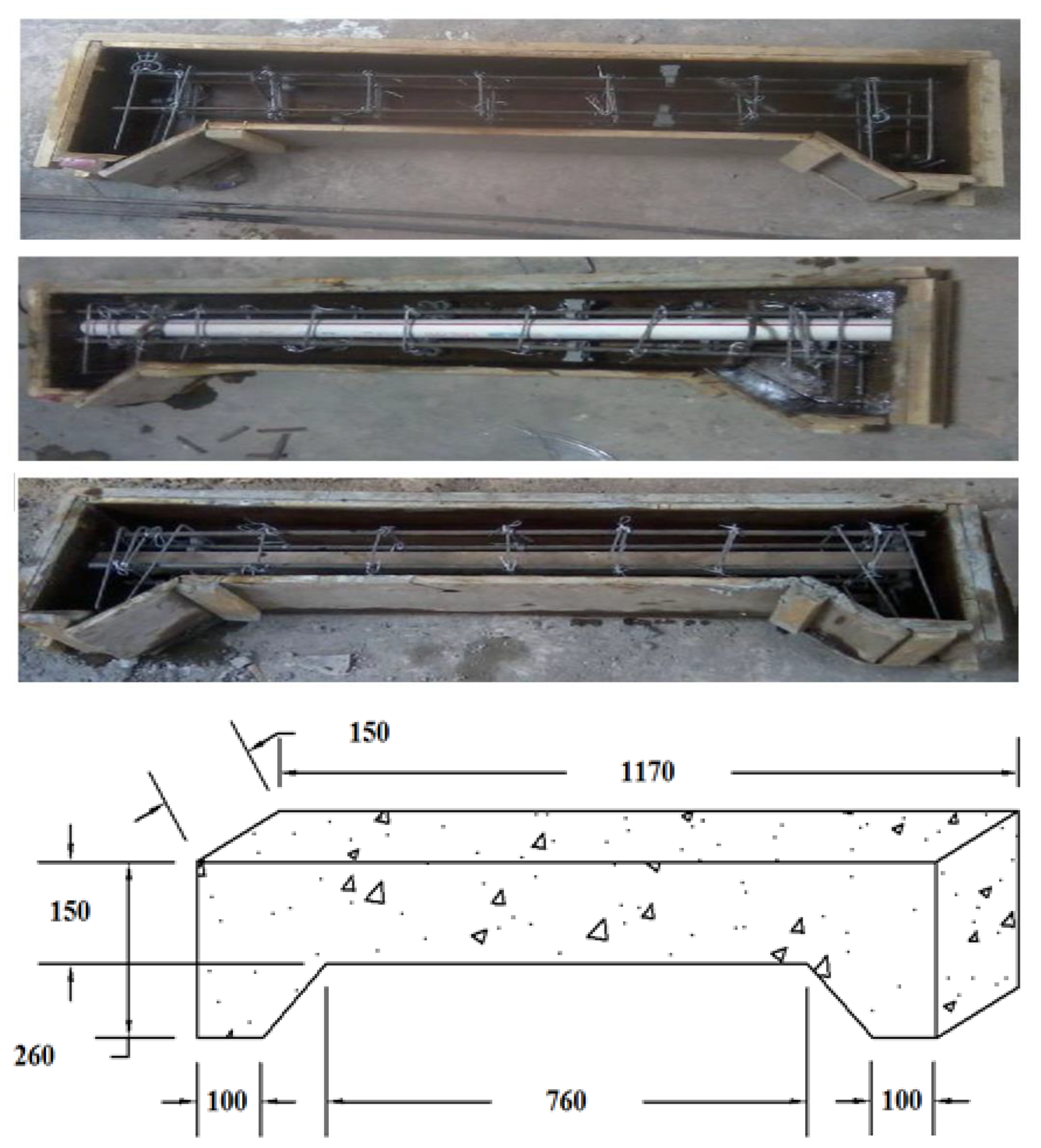
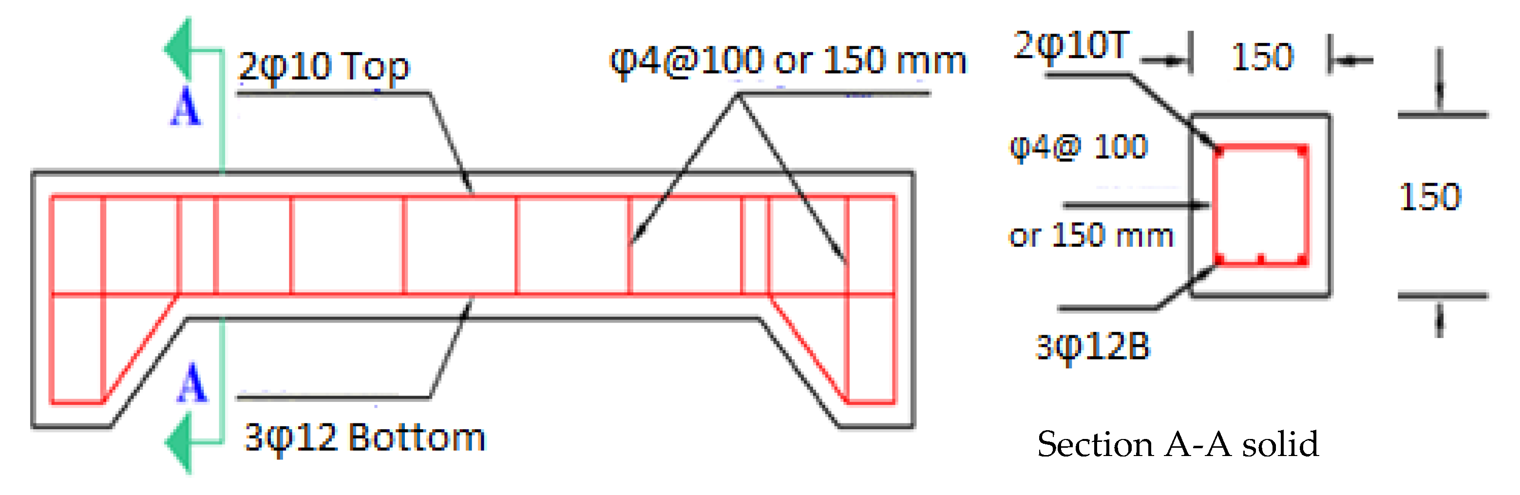
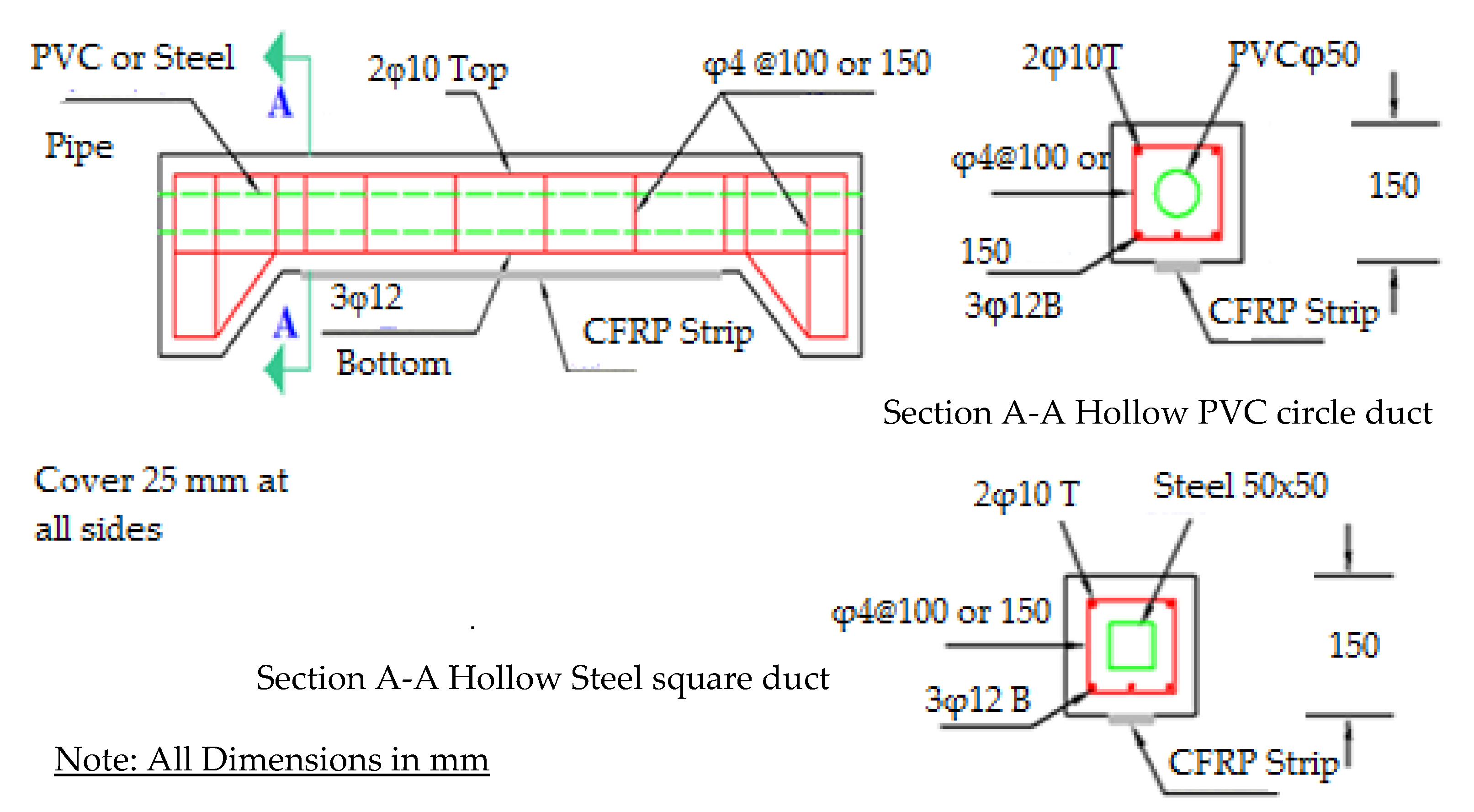
2. Profiles of the Numerical Beam Models

Dimensions and characteristics of the simulated models of non-prismatic beams and hollow cross sections were taken from the previous study [23]. Hence, these models were designed according to ACI-318 [37]. Moreover, the layers of CFRPs were added to the flexural region of the models according to ACI-440-2R [38]. The detailed design of these beams can be found in the previous experimental study [23]. Further, these models were simulated by using ANSYS [36]. The models consisted of a set of beams with a total length of 1170 mm, a width of 150 mm, and a depth of 260 mm. However, the depths were irregular at the ends of the supports. Some models were hollow in the middle of the section, i.e., in the core of the model, and the cavities were different in terms of shape, size and type. The characteristics and profiles of the non-prismatic RC beam models are listed in Table 1. There were two groups of non-prismatic and hollow beam models using a longitudinal recess along the length of the models using a plastic duct with a diameter of 50 mm. However, the second group included a longitudinal recess of a square steel tube with dimensions of 50 mm × 50 mm for each side. These models were retrofitted with CFRPs and compared with the solid model, which is considered here as a reference model for comparison in order to obtain an equivalent load bearing capacity for the hollow models. The main parameters in this study included shear steel reinforcement, the shape and type of the recess created in the models. Hence, the dimensions of the recess were specified as a ratio of the transversal cross-section of the beams to ensure a durable concrete cover, as stated in [23]. The main reinforcements included 3Ø12 mm bars (AS) at the bottom against tension, and 2Ø12 mm bars (AS’) at the top against compression for all models, as stated in the previous study [23].

2.1. Mechanical Properties of Materials

The mechanical properties of the used materials to form the non-prismatic RC beams were taken from the previous study [23]. These properties for concrete, reinforcing steel and CFRPs are listed in Table 2, Table 3 and Table 4. These properties were used as the input data for the numerical models that were simulated by using ANSYS [36]. The moulds, steel reinforcements, the locations and arrangements of the recesses are shown in Figure 1, Figure 2 and Figure 3 for the solid and hollow sections, respectively [23].

2.2. Assumptions

The basic assumption in this numerical study for analysing solid and hollow non-prismatic beams retrofitted with CFRPs, was that both concrete and reinforcing steel materials were homogeneous and isotropic. Full bonding between the reinforcing steel bars and concrete within the specified elements was considered, and they were only connected by nodes. In addition, in the numerical simulations, CFRPs were linked as specified areas with the model nodes of concrete beams to ensure full bonding within the elements [35]. In addition, it was assumed that a plane would remain plane and the stress–strain relationship of the reinforcing steel was assumed to be elastic-perfectly plastic. The concrete was represented by nonlinear characteristics through a homogeneous multiphase simulation model, i.e., multilinear and isotropic. An imposed model can accept stresses and strains for many points within the plastic range as a result of adopting the mechanical properties of concrete. Hence, the increases of stresses with strains were simulated in accordance to a plastic model that obstructs a point or a curve when its slope is less than zero, which is unacceptable. Numerically, to simulate numerical models using ANSYS [36], the bilinear model was used to predict the nonlinear behaviours of steel rebars, which were defined by the mechanical properties of steel including the yield stress. The rebar diameter and elastic modulus was predefined within the ANSYS program. However, to the simulated CFRPs, their mechanical properties were also defined within the program by the yield stress, elastic modulus and thickness.

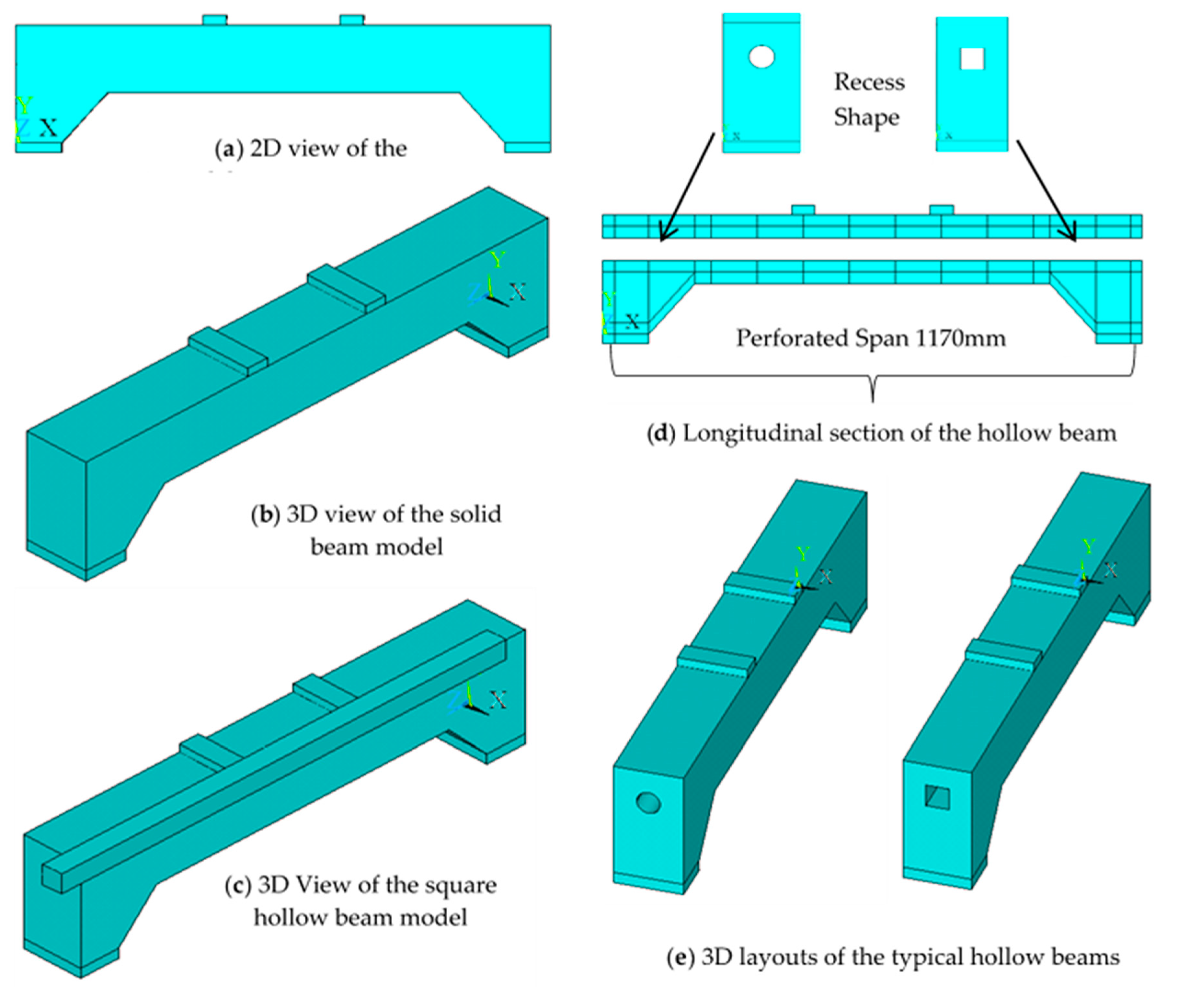
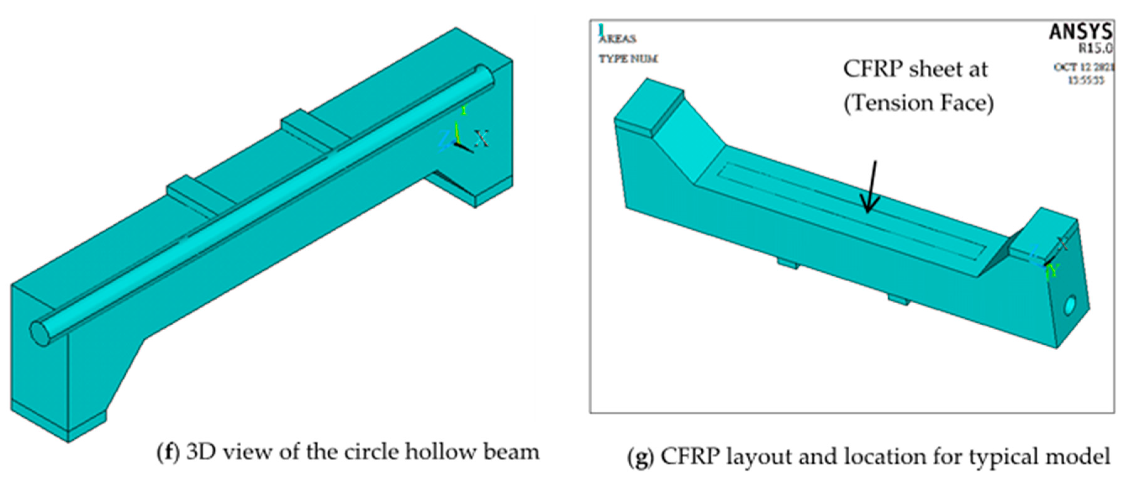
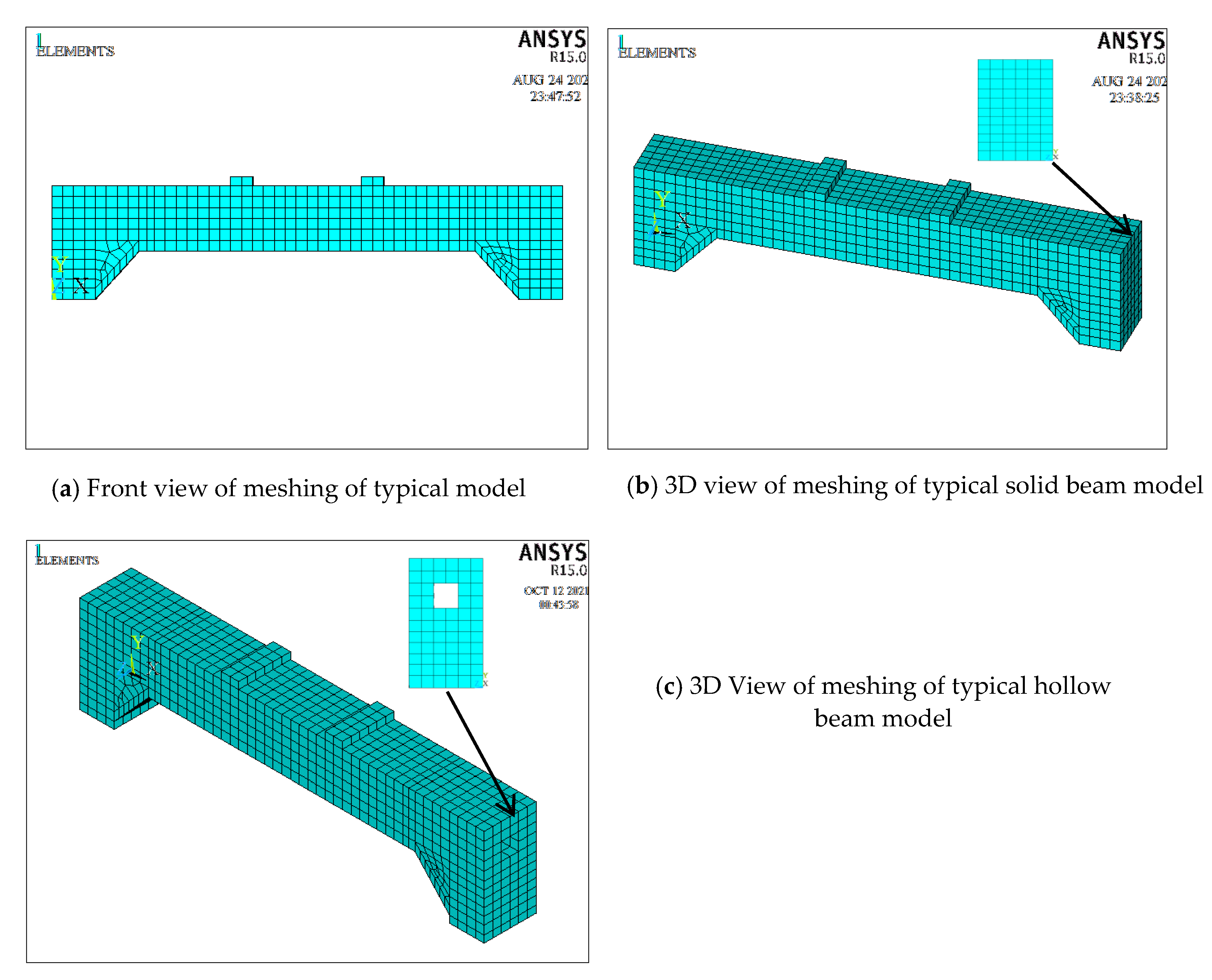
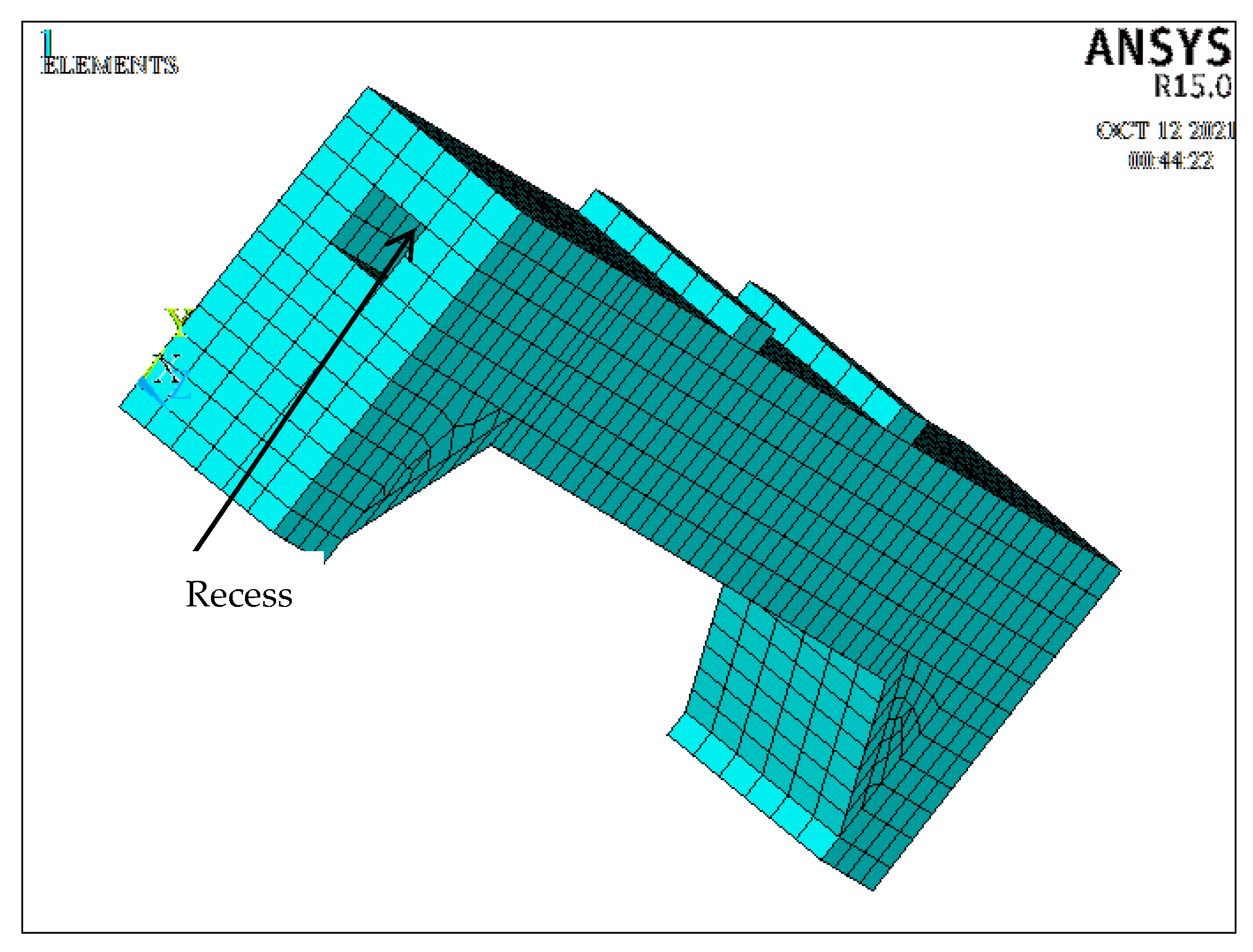
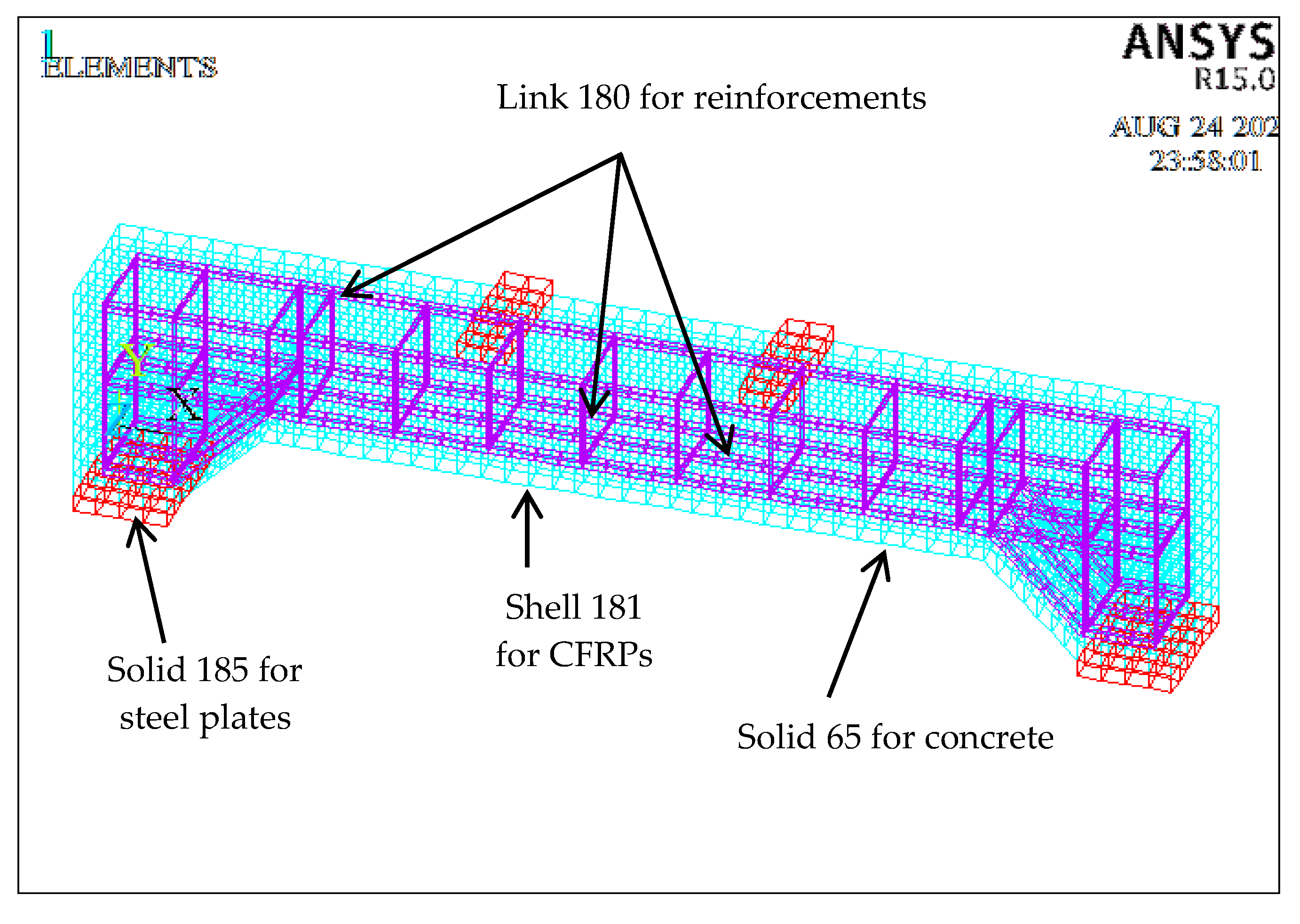
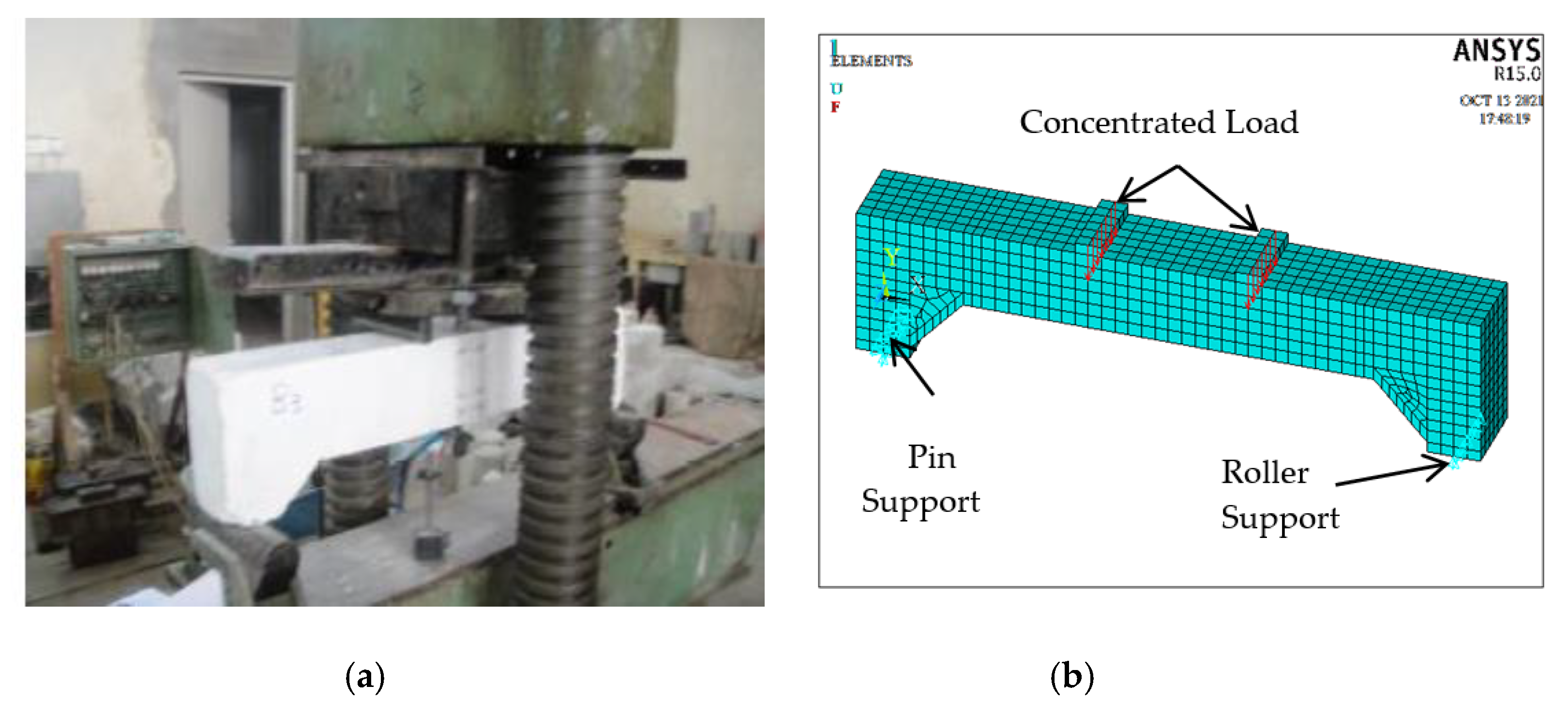
3. Finite Element Modelling

The established numerical models were analysed by using ANSYS [36]. Elements were selected within the program to closely represent the actual models of the materials that make up the non-prismatic beams. Different characteristics were determined for the beams, loading cases and supports. The materials for the RC beam models were simulated including concrete, steel plates, steel reinforcement and CFRPs. The solid element 65 was used to model concrete, which has three degrees of freedom at each node. Reinforcing steel bars with various diameters were modelled by using the link element 180 which had double nodes with three degrees of freedom for each note. The solid element 185 was used to model steel plates under the supports and applied loads, and has eight nodes, with three degrees of freedom for each node. Finally, the CFRPs were represented by shell element 181, which has eight nodes with three degrees of freedom at each node [22,35]. The modelling process was carried out by dividing the model through meshing to get small elements, with the length of an element being 25 mm in each direction. These elements were connected to each other by means of nodes, which connect each of the reinforcing steel to concrete components, or link CFRPs to the model elements. Thus, the bond between different materials was simulated by means of nodes within a model, which were merged to one node during the simulation. Therefore, completely full bonding was assumed between all parts and components of the simulated model.
The simulated models were modified in comparison with the previous experimental results [23]. Behaviours of comparative models, i.e., solid and hollow models retrofitted with CFRPs, were simulated by applying deflections. The coefficients for defining opening and closing concrete cracks need to know and were set as 0.2 and 0.7, respectively. The characteristic stress–strain relationships of both concrete and steel materials were assumed to be elastic-perfectly plastic.
The stress–strain curve of concrete for the RC beam components was formulated by the program. This constitutive law assumed the stress–strain relationship was linear up to 0.85 fc’ and then became completely plastic until the concrete strain reached 0.003. Furthermore, the main assumptions specified that a plane section remained plane before and after loads were applied, the model was homogeneous, full bonding of concrete with reinforcements and CFRPs was maintained, and the self-weight of the RC beams model was neglected. Figure 4, Figure 5 and Figure 6 show the wireframes for all parts of the non-prismatic RC beam models, their dimensions and details, including longitudinal and transverse reinforcing steel, locations, shape and type of cavities, steel plates at supports, retrofitting CFRPs, support conditions, and loading patterns that were modelled and simulated for the numerical analysis using the ANSYS software [36].
The following steps include the meshing of the simulated models with the ANSYS [36] through the mesh tools, and the inclusion of the appropriate properties and elements for each material within the model and the constants within the formulation, where the formed volumes were initially divided into small elements, each being 25 mm long in all directions, as shown in Figure 5 and Figure 6. These figures show the representations of non-prismatic RC beams by finite elements by indicating the front, side and three dimensional views of the models and the locations of individual elements.
Figure 7 illustrates the representations of individual simulated materials. As for the finite element types, the solid element 65 was used to represent concrete, the solid element 185 was used to represent steel plates below the supports and at the loading points, the link element 180 was used to model longitudinal and transverse reinforcements, and the shell element 181 was used to model CFRPs.
Figure 8 illustrates the layouts of the experimental and numerically modelled supports and loadings. Similar to the actual test specimens, the right end support was restricted in a direction perpendicular to the loadings so that it was simulated as a roller support, while the left end support was restricted in the vertical direction, and the longitudinal direction was parallel to the specimen length of the model and, hence, was simulated as a hinge support. Two concentrated loads were placed at the intermediate nodes for the steel plates, as shown in Figure 8. Numerically, the loading increment was every 5 kN till the first cracking and failure loads. This step is similar to those in the experimental study [23].

4. Results and Discussion

Five models of non-prismatic solid and hollow RC beams were numerically analysed by using the ANSYS finite element program [36]. The simulations of these models were performed by defining the mechanical properties and constants for all the materials that formed those beam models, as well as the loading and support conditions to represent the specimens from the previous experimental investigations [23].
This section will explain the basic relationships of the models that were simulated in order to analyse and then compare the obtained responses with the reference model. In this study, the structural behaviours of RC beams depended on many parameters, such as the configuration of the section, i.e., solid or hollow, shear reinforcement and CFRP retrofitting.
The obtained numerical results showed that all the models failed in shear, but with different intensities according to the characteristics and parameters of individual simulated models. It is clear that all beam models had cracks. In particular, the beam models with a recess in their cores had more cracks than the solid beam models, because the solid concrete core had an effect on increasing the load ability and reducing cracks according to the utilised total area of the section [22,35].
Figure 9 and Figure 10 illustrate the distributions of the hydrostatic stress for typical solid and hollow beam models, where the stresses are diagonal, depending on the type, direction and location of the applied loadings [31,35]. These stresses are concentrated at the mid-span, top chord, and supports of the beams. Additionally, the stresses are larger when the model is hollow because it is weak and less stiff under the same loading, which leads to the larger stress concentrations in that section, in particular around the core of the beam model, in comparison to the solid model, by 21 to 33% [35,39,40]. During the analysis, it is also found that that the shear reinforcement, as well as the retrofitting CFRPs, decreased the values of these stresses, i.e., improving the stress distribution state so as to enhance the load resistance by 12 to 18%. This effect of using transverse shear reinforcement on the distribution of stresses and ductility of RC beams was also stated in [41,42].
Figure 11 and Figure 12 illustrate the von Misses stresses and strains of typical RC solid and hollow beam models. It is noticed that these stresses increased in the regions of supports, loading areas and recess locations within the beam models. These behaviours were caused by the way of distributing the stresses that come from the applied loads within the models [31,35,36,39,40].
In general, during the numerical analysis process, it was observed that the resulted deflections increased when the sections of the non-prismatic RC beams contained a recess, in comparison to the solid section, due to the existence of a recess that would reduce the load carrying capacity and increase the corresponding deflections. It was also found that the increase in shear reinforcement has an enhancing effect on developing and improving the behaviours of the beam models by reducing deflections and increasing loading carrying capacity. For hollow sections, however, it was found that increasing the shear reinforcement could hold the concrete parts together and compensate the deficiency caused by the presence of the recess to some extent. This could also improve the load carrying capacity and reduce the deformations or deflections of the beam models. Similar behaviours were also observed when strengthening beam models with CFRPs. These behaviours of the numerically analysed beam models were identical to those of the actual RC beams in the previous experimental examinations [23]. Contour lines of deflection values for typical RC sections can be shown in Figure 13 and Figure 14.
Figure 15 illustrates the cracking patterns and their distributions within the numerical beam models by the ANSYS program [36], as well as from those from the previous experimental investigations [23]. The crack patterns of the beam models were taken for the controlled solid and hollow RC beam models. From a numerical analysis, the failure modes of the beams all showed shear failure patterns which are identical to the experimental results [23]. The specific types of finite elements helped to achieve accurate predictions of failure patterns where the cracks were concentrated near the supports and extended in a diagonal direction towards the points of the applied concentrated loads. These cracks became less tense in the middle parts of the beam models and were affected by the type of cross section, i.e., solid or hollow. It was also found that increasing the transverse reinforcement as a link belt for the concrete parts could reduce the number of cracks. Moreover, strengthening or retrofitting with CFRPs could enhance the load carrying capacity of the beam models and, consequently, decrease the number of cracks.
The conducted numerical analysis included the applied loads, which were taken as the same loads in the previous experimental investigations [23] with a gradual load increment of 5 kN. The numerical responses of the numerical beam models were evaluated in terms of the deflections at the middle span of beams, i.e., 585 mm from each support. Thus, these locations matched the positions of the dial gauges on the previous tested beams [23], as shown in Figure 16.
Figure 17, Figure 18, Figure 19 and Figure 20 illustrate the comparisons of the numerical load versus mid-span deflection curves of the non-prismatic RC beam models with the experimental curves under the applied concentrated loads for different influencing parameters. As stated, these parameters included the beam section configuration, i.e., solid or hollow section, the recess type and shape, the reinforcement ratio and the retrofitting CFRPs. The deflections in all loading stages were calculated and evaluated. It was found that the deflections increased by 18–26% with the use of the hollow sections, as a result of weakening the sections and reducing the load carrying capacities. As for the recess type, it was found that a circular recess could produce a higher resistance than a square recess as a result of the higher moment of inertia of the circular shape than that of the square one. This would increase the resistances and reduce the stresses by 10–13%. An increase in the percentage of shear reinforcement could help to hold the concrete parts and other components together, which led to higher resistances by 20–31% and lower corresponding deflections by 16–22%. Retrofitting CFRPs could strengthen and hold the concrete parts in the tensile area so as to increase the maximum load bearing capacities and decrease the corresponding deflection. These benefits of increasing the shear reinforcement and utilising the retrofitting CFRPs in the hollow beams could produce the equivalent load bearing capacities and stiffness to the solid beam sections. Further, in terms of stiffness for the simulated beams, this property is larger and more varied at the supports for the solid beam than in other positions of the beam due to its varied depth at the supports. However, the stiffness is smaller in the hollow beams than in the solid ones due to the effect of the hollow core.
Figure 21 and Figure 22 illustrate the comparisons of the experimental and numerical results of the strains in the tensile and compressive regions at failure, respectively. It is noticed that the strains increased by 20–25% when the cross sections of the numerical beam models changed from solid to hollow. The hollow sections with steel pipes caused smaller strains in comparison to the other sections due to the contributions of the steel pipes towards the increased stiffness and reduced deformations. Hence, the beam model with a circular recess showed a higher load carrying capacity than the square one, due to its higher moment of inertia, while a square recess formed with a steel tube could produce an additional resistance of 56% in comparison with other hollow sections, i.e., circle PVC pipe, due to the composite effects of concrete components and steel materials.
Table 5 illustrates the comparisons of the experimental and numerical results in terms of the deflections at the first cracking and failure loads, while Table 6 illustrates the results of the statistical analysis by including the mean and standard deviation values of the deflections at the first cracking and failure loads along with the ductility index, which was defined as the ratio of the deflection at the failure load to the one at the first cracking load. It is noticed that the standard deviations became larger when the applied loads increased, and the presence of recesses in the longitudinal sections of the RC beam models also increased the standard deviations with the increasing applied loads. This is compatible with both the arithmetic mean and the standard deviation values of the ductility indexes when comparing the numerical analysis results with the experimental results, as shown in Table 6. Further, the correlation coefficient, termed as R2, between the experimental and numerical deflection values at first cracking load is 0.9891. However, at failure load the correlation coefficient, R2 is 0.9975. Statically, these high values indicate an excellent agreement between the experimental and numerical behaviours of the beams.
It can also be noted that the arithmetic mean value of the relative ductility index, i.e., the ratio of the numerical ductility index to the experimental ductility index, was 1.018. This indicates that the ductility index could be influenced by other parameters, including the shear reinforcement ratio, the section configuration (solid or hollow), the shape and type of recess, etc. It was found that increasing the shear reinforcement could enhance the load bearing capacities of the beam models and decrease the corresponding deflections. Meanwhile, the hollow sections could decrease the load bearing capacities of the sections by up to 50% and increase the corresponding deflections by 23–40%. The obtained numerical results of the ductility index show an excellent agreement with the experimental ones [23]. The ductility index values were low when the cross-section changed from solid to hollow. Finally, it can be noted that the specific types of finite elements that were utilised for the numerical modelling, using the ANSYS program [36], helped to obtain excellent good agreements of the numerical results with those from the experimental study [23]. This provides the opportunity to conduct numerical studies on the effects of other parameters, i.e., the cylinder compressive strength of concrete was adopted here as a parameter for numerically analysing models. Further, this study can be extended by considering other parameters that are not discussed here and can be used for the purposes of future construction and design.

5. Other Studied Parameters

This study also explored some other parameters that could have effects on the structural behaviours of non-prismatic hollow and solid RC beams. The compressive strength of concrete was chosen as an important parameter due to its direct role in governing the performance of the beam section. Numerical analyses on ten additional RC beams were conducted as shown in Table 7. The selected compressive strength values were 26.63, 42.00 and 55.00 MPa, respectively.
The obtained numerical results in comparison with the previous experimental results [23] by adopting the maximum loads and the corresponding deflections are illustrated in Table 7 and Figure 23. The increase in the concrete strength enhanced the maximum loading capacities of the beams by 23 to 29% and decreased the corresponding deflections by 31 to 45%. Hence, the use of higher concrete strength could have a vital role in reducing deformations and improving the ductility.

6. Conclusions

In this study, a numerical analysis was conducted using the ANSYS software [36] on the solid and hollow non-prismatic RC beams subjected to two equal concentrated loads. The numerical results were compared with the experimental results from the previous study and the following conclusions can be drawn:
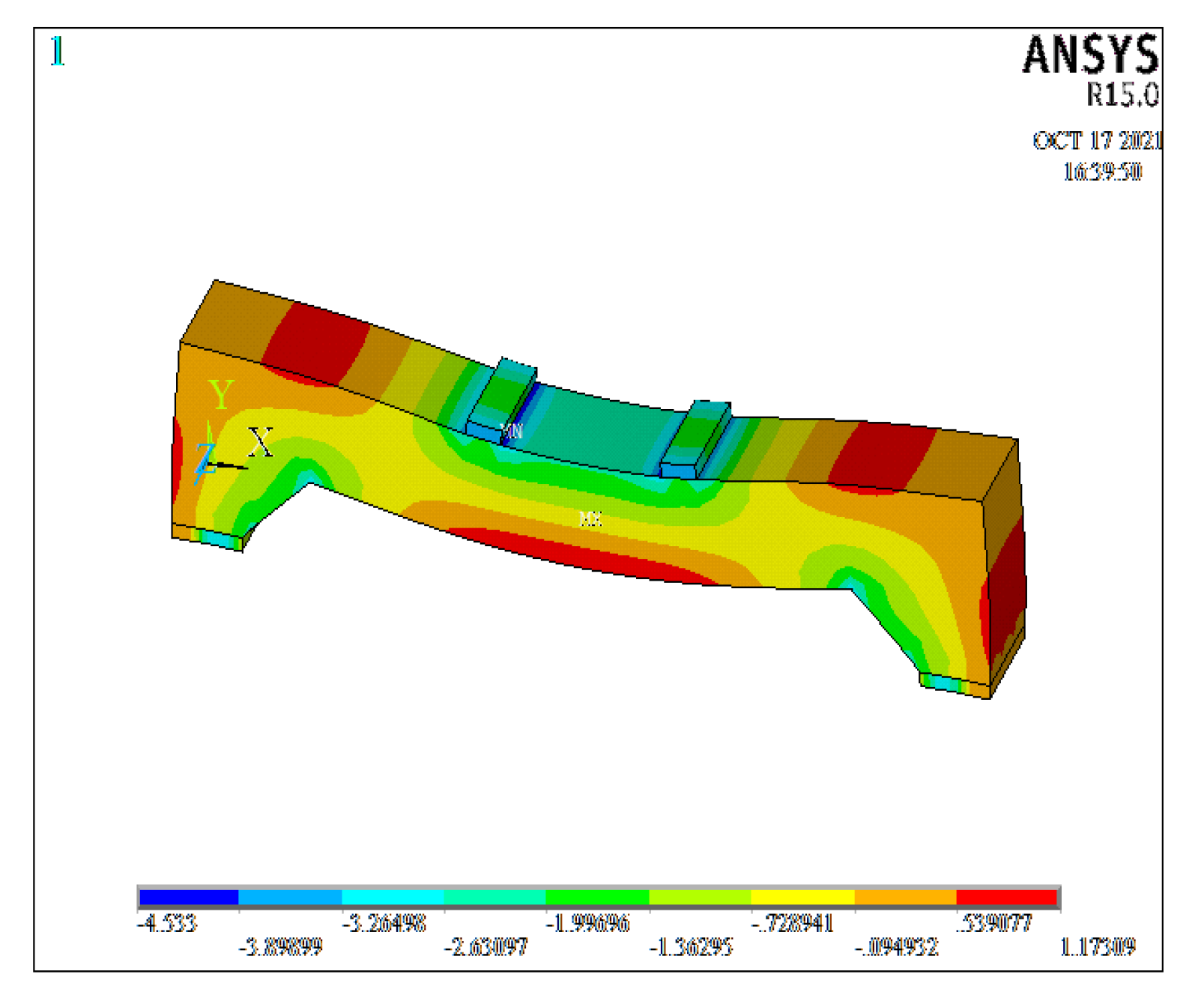
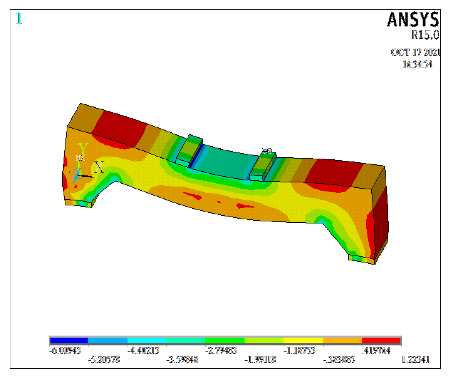
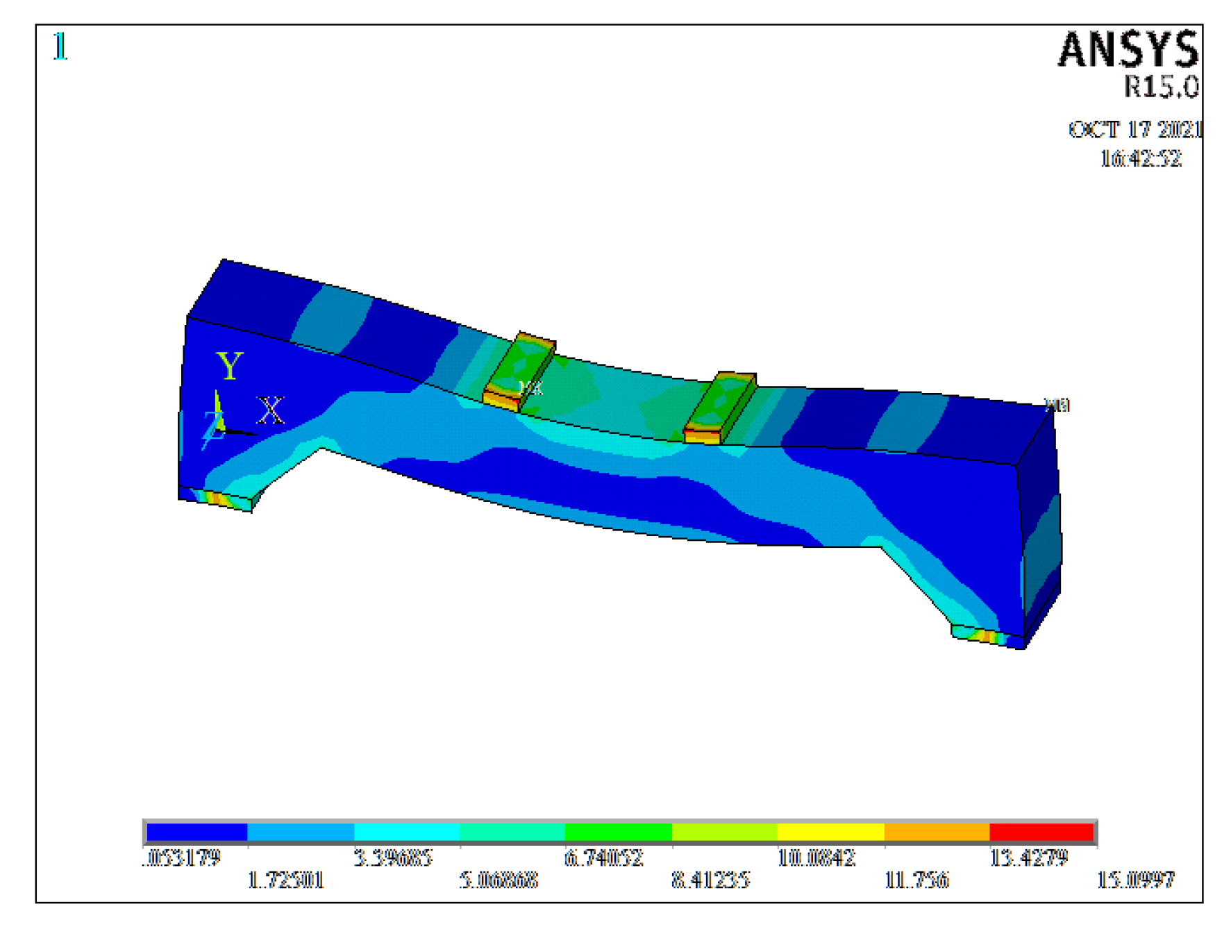
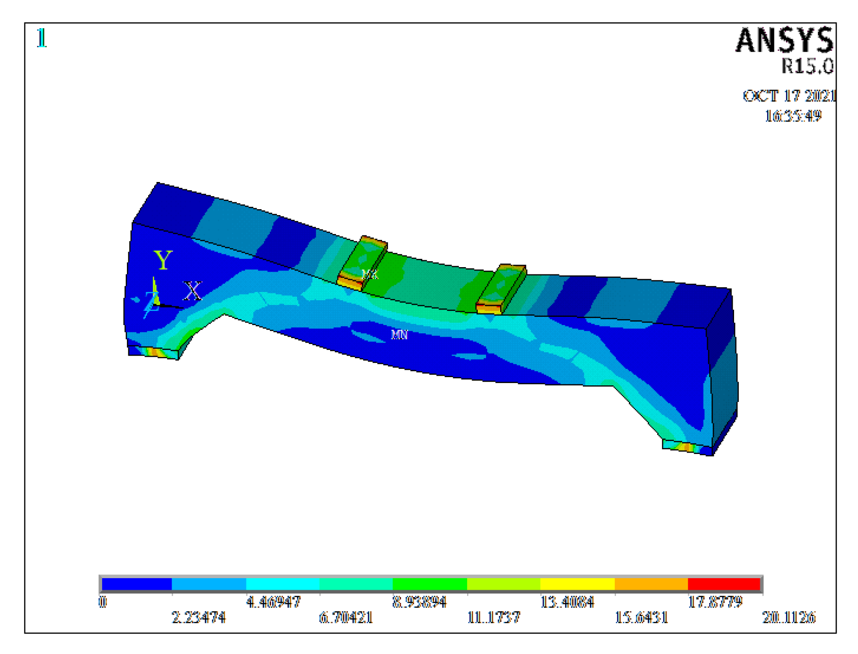
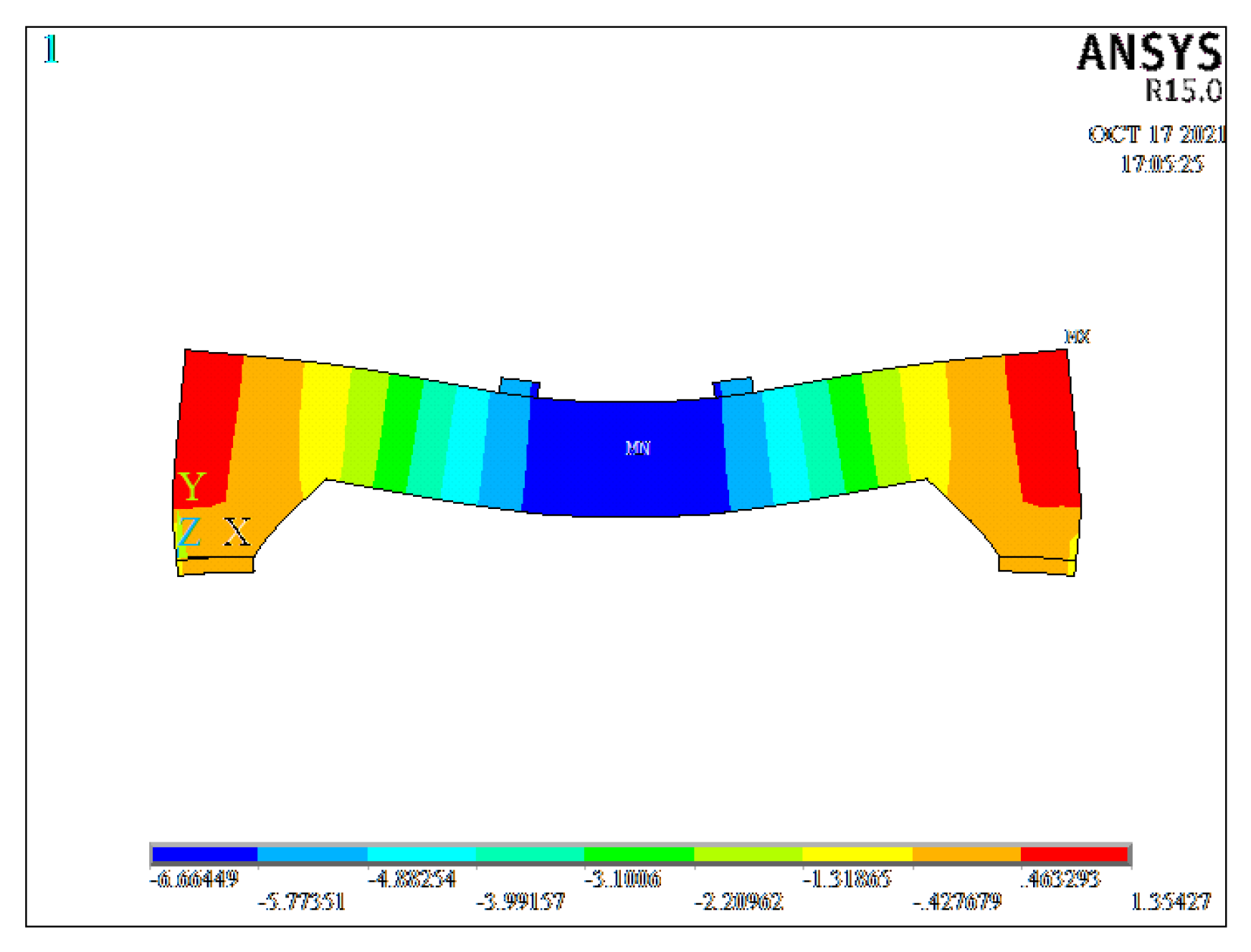
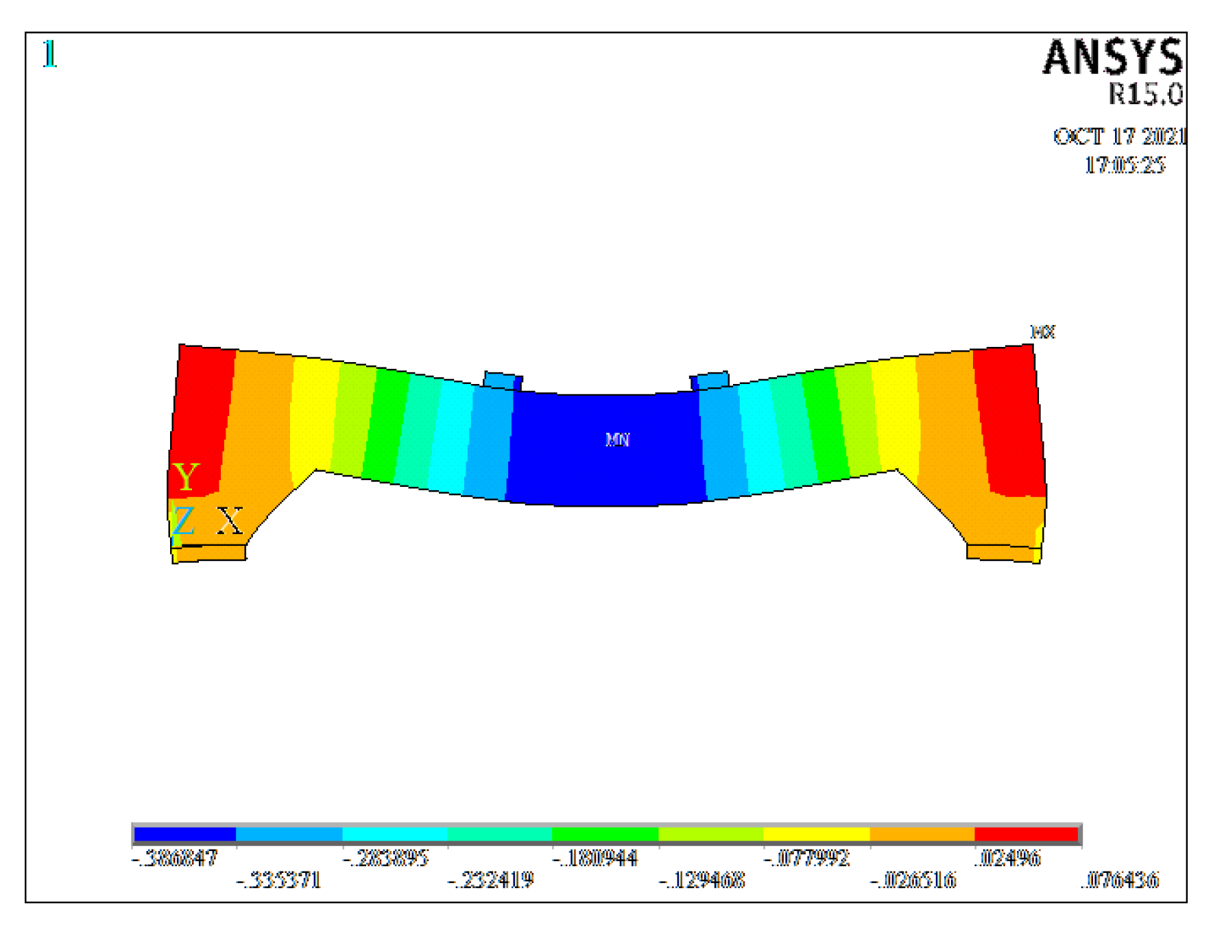
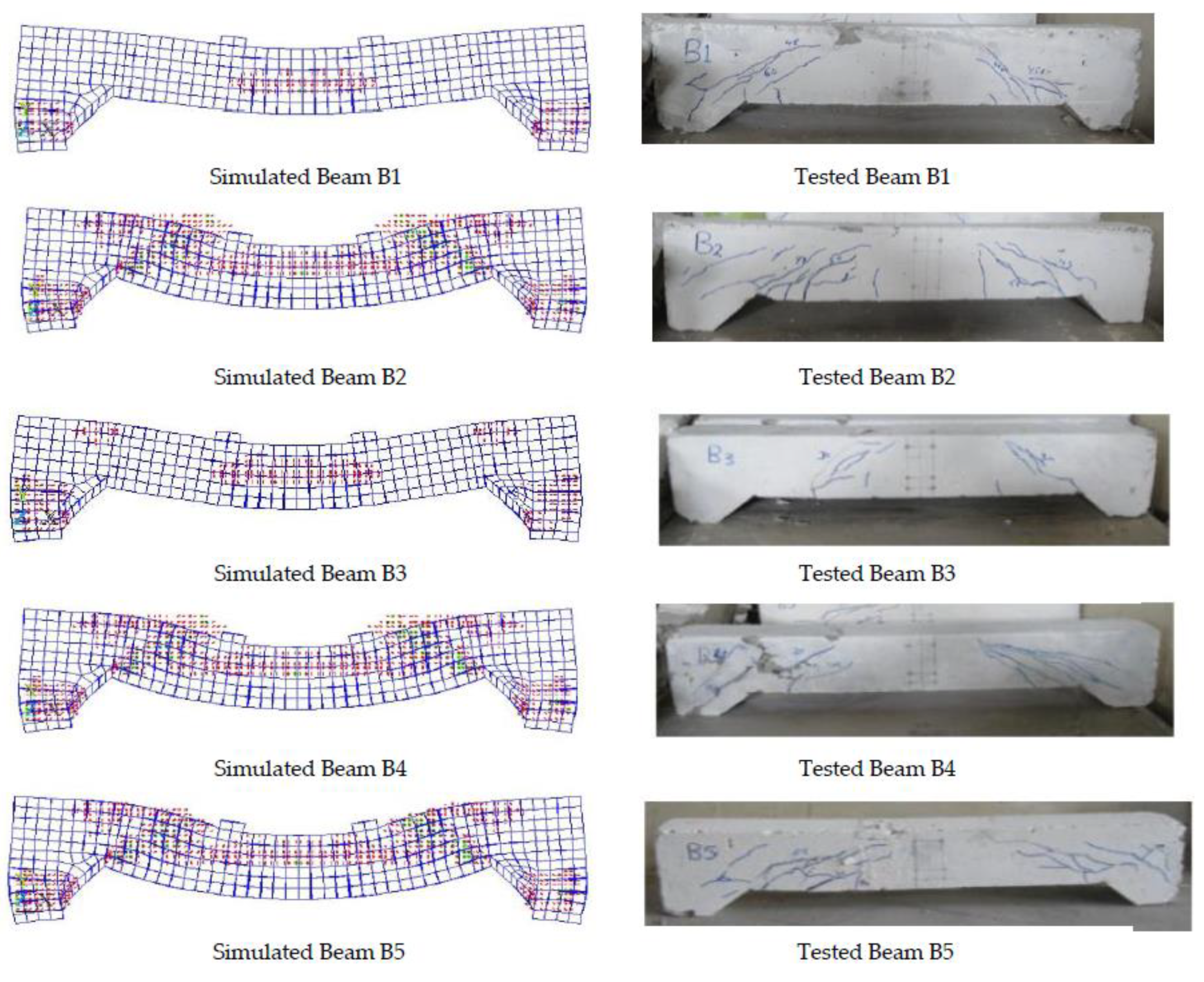
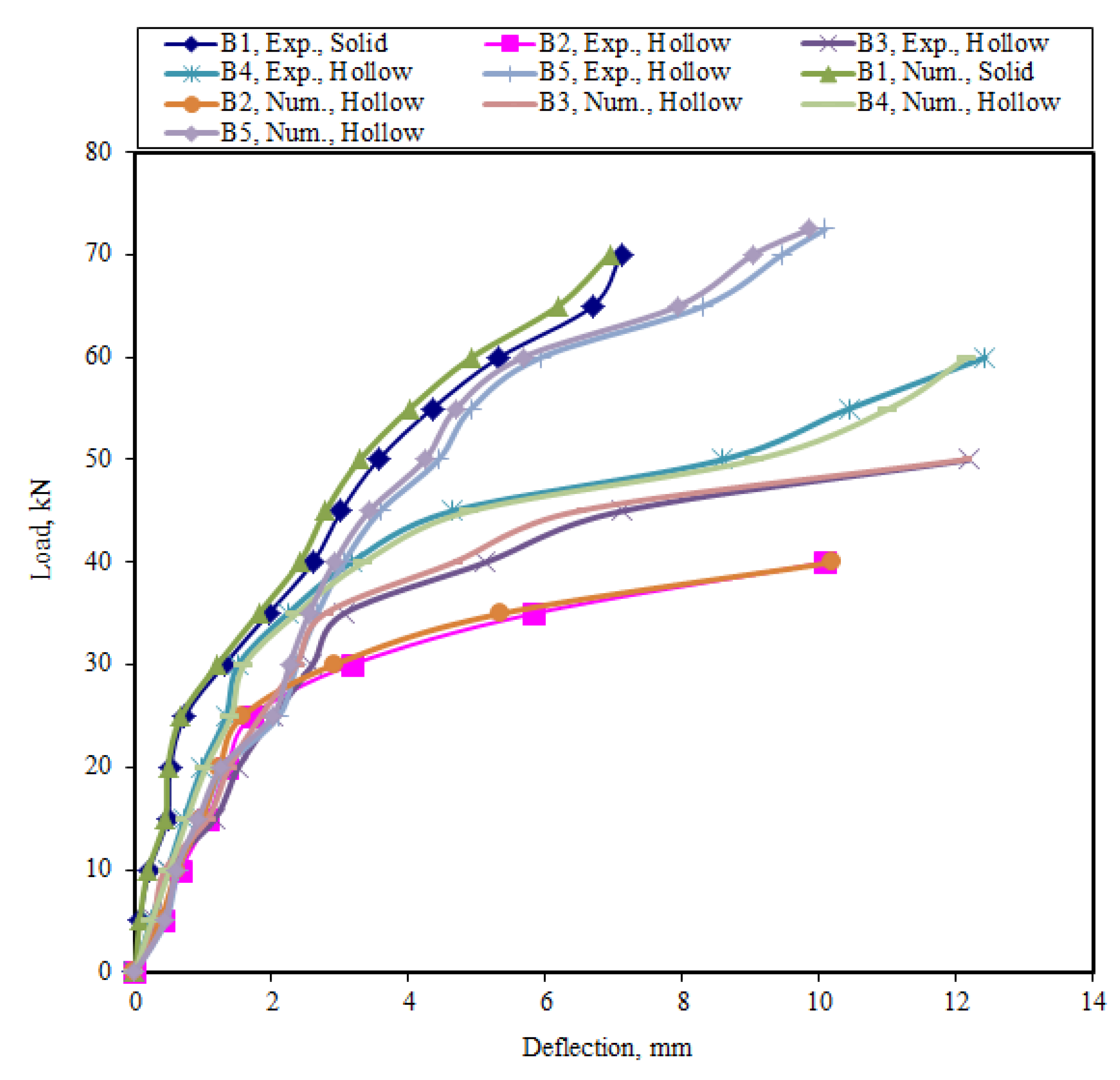
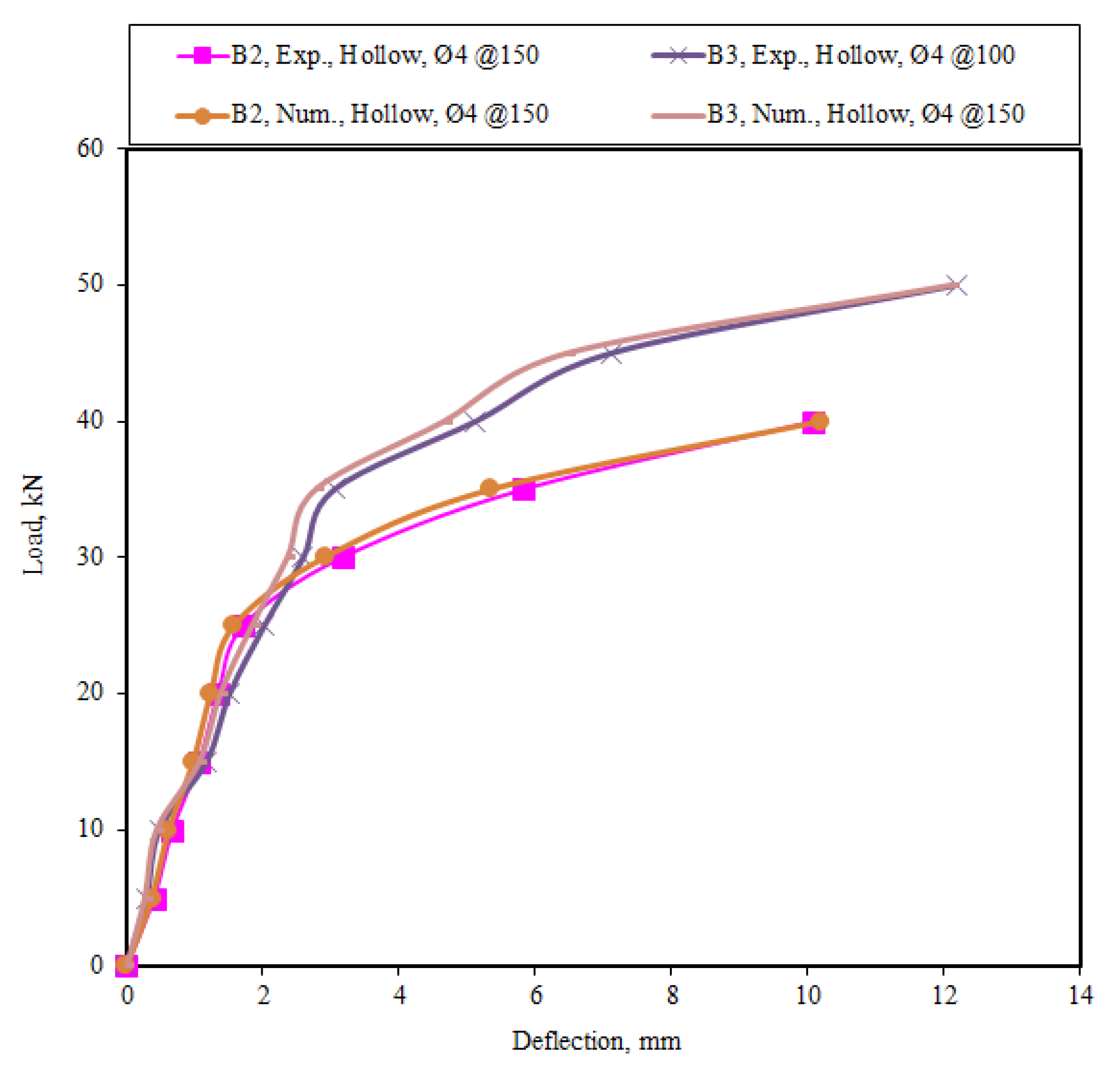
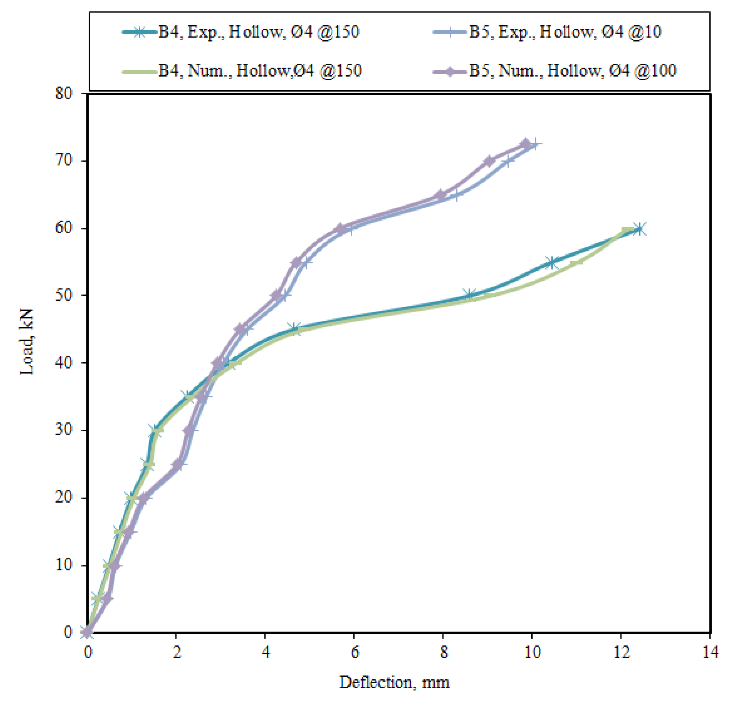
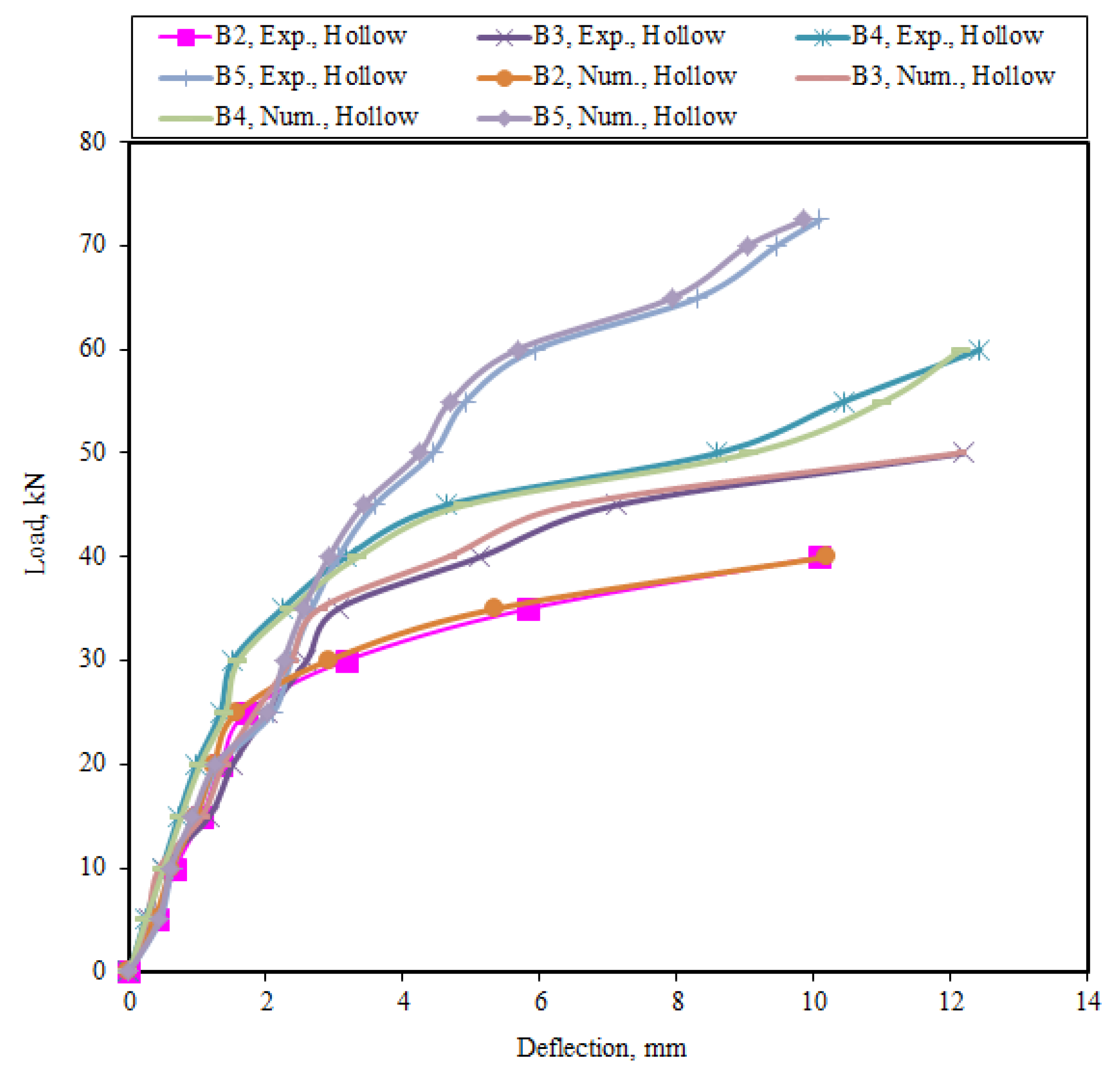
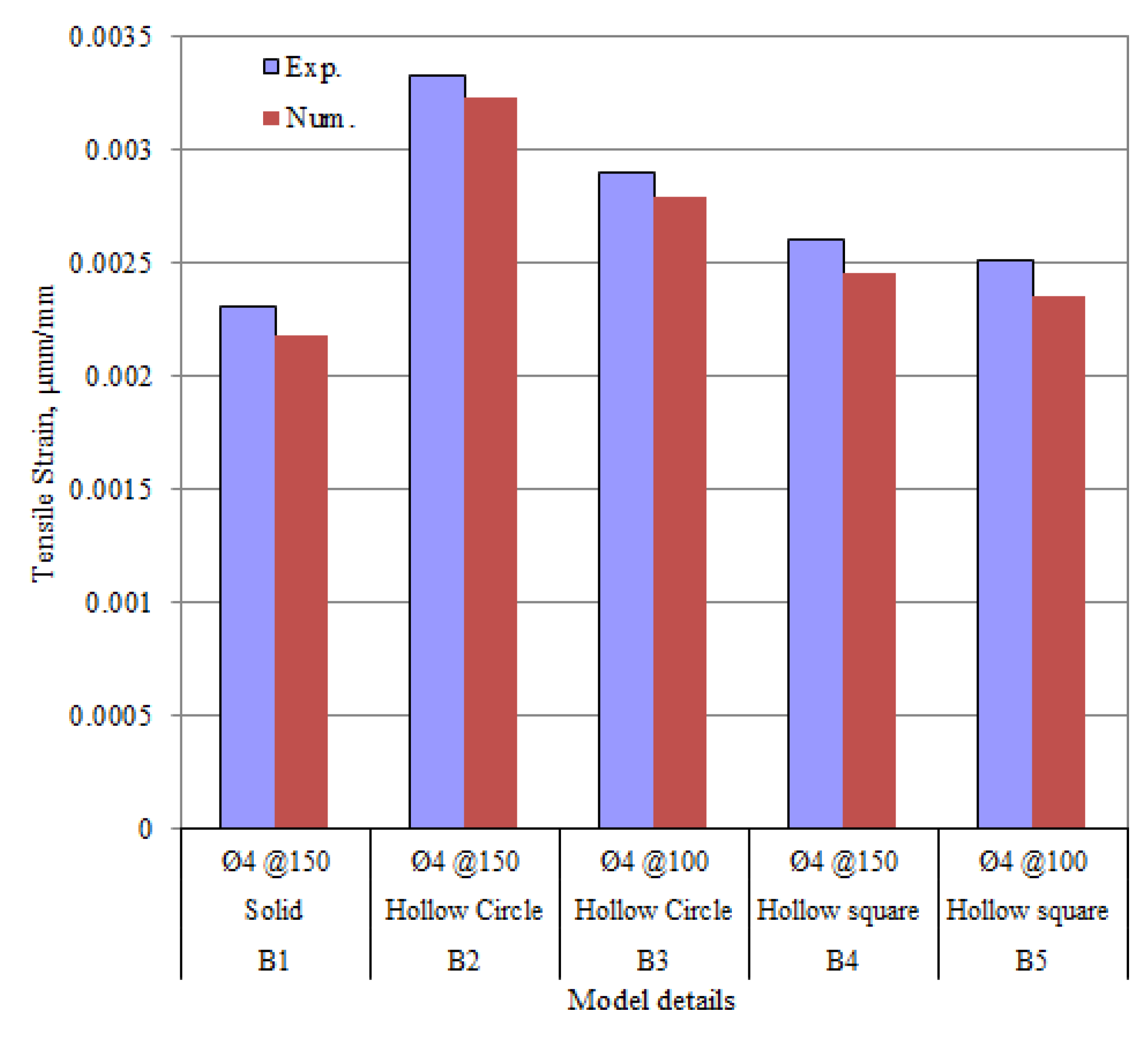
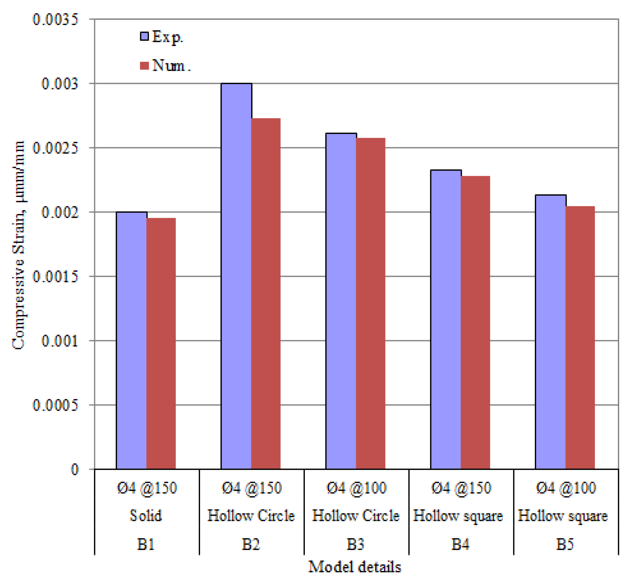
  • The numerically simulated results could accurately predict the structural behaviours of the RC beam models and showed excellent agreements with the experimental results in the previous study.
  • The maximum load carry capacities of the solid beam models were larger than those of the hollow ones by 17–53% for the same characteristics due to their better ductility performances.
  • The mid-span deflections of the RC beam models increased by 33–40% when the sections changed from solid to hollow. Meanwhile, the surface strains increased by 21–25% in both numerical analysis and experimental test results in the hollow RC beams with recesses.
  • An increase in shear reinforcement by 50% could increase the load carrying capacities of the beam models by 30% and decrease the corresponding deflections by 24%. Meanwhile, this could enhance the ductility of all RC beam models by 22–40% while keeping other characteristics unchanged.
  • The CFRPs sheets attached in the tensile part in the middle regions of the RC beams could improve the load carrying capacities of the beam models and decrease the corresponding deflections.
  • The failure modes for all the simulated beam models were in shear failure patterns and were identical with the experimental investigations.
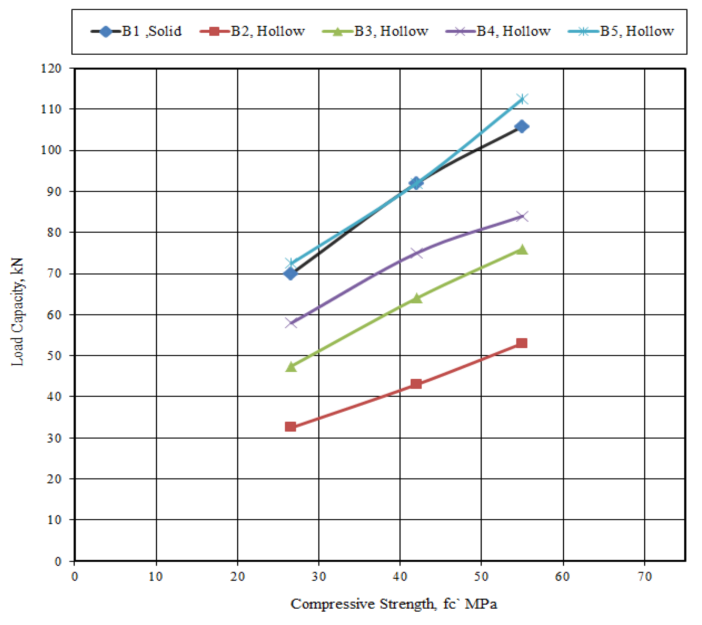
  • The further numerical analysis indicated that the compressive strength of concrete had an important effect on enhancing the load carrying capacities of the RC beam models.

Author Contributions

Conceptualization, A.J.H.A. and H.N.G.A.-M.; data curation, A.J.H.A., E.K.J., L.A.S. and H.N.G.A.-M.; formal analysis, H.N.G.A.-M.; funding acquisition, A.J.H.A., E.K.J. and L.A.S.; investigation, A.J.H.A., E.K.J., L.A.S. and H.N.G.A.-M.; methodology, A.J.H.A., E.K.J., L.A.S. and H.N.G.A.-M.; resources, A.J.H.A., E.K.J., L.A.S., H.N.G.A.-M., A.A.-B. and B.Z.; validation, H.N.G.A.-M.; visualization, H.N.G.A.-M.; Writing—original draft, H.N.G.A.-M.; Writing—review & editing, A.A.-B. and B.Z. All authors have read and agreed to the published version of the manuscript.

Funding

This research received no external funding.

Data Availability Statement

The data are available upon request from the first author of the paper.

Acknowledgments

The authors would like to thank Mustansiriyah University, (https://uomustansiriyah.edu.iq/) (accessed on 15 December 2021) and University of Baghdad, (https://uobaghdad.edu.iq/) (accessed on 15 December 2021), Baghdad, Iraq, for their support in the present work. Also, the authors from these universities are very grateful for the cooperation with Glasgow Caledonian University in Scotland, UK.

Conflicts of Interest

The authors declare no conflict of interest.

References

  1. Park, R.; Paulay, T. Reinforced Concrete Structures; John Wiley & Sons: New York, NY, USA, 1975. [Google Scholar]
  2. Alnuaimi, A.S.; Bhatt, P. Direct design of hollow reinforced concrete beams, Part II: Experimental investigation. Struct. Concr. J. 2004, 5, 147–160. [Google Scholar] [CrossRef]
  3. Al-Nuaimi, A.S.; Bhatt, P.; Al-Jabri, K.S.; Hago, A. Comparison between solid and hollow reinforced concrete beams. Mater. Struct. 2008, 41, 269–286. [Google Scholar] [CrossRef]
  4. Hassan, N.Z.; Ismael, H.M.; Salman, A.M. Study behavior of hollow reinforced concrete beams. Int. J. Curr. Eng. Technol. 2018, 8, 1640–1651. [Google Scholar] [CrossRef]
  5. Balaji, G.; Vetturayasudharsanan, R. Experimental investigation on flexural behaviour of RC hollow beams. Mater. Today Proc. 2020, 21, 509–516. [Google Scholar] [CrossRef]
  6. Hemzah, S.A.; Alyhya, W.S.; Hassan, S.A. Experimental investigation for structural behaviour of self-compacting reinforced concrete hollow beams with in-place circular openings strengthened with CFRP laminates. Structures 2020, 24, 99–106. [Google Scholar] [CrossRef]
  7. Abbass, A.; Abid, S.; Özakça, M. Experimental investigation on the effect of steel fibers on the flexural behavior and ductility of high-strength concrete hollow beams. Adv. Civ. Eng. 2019, 2019, 8390345. [Google Scholar] [CrossRef]
  8. Mansur, M.A. Effect of openings on the behaviour and strength of R/C beams in shear. Cem. Concr. Compos. 1998, 20, 477–486. [Google Scholar] [CrossRef]
  9. Katzer, J. Strength performance comparison of mortars made with waste fine aggregate and ceramic fume. Constr. Build. Mater. 2013, 47, 39. [Google Scholar] [CrossRef]
  10. Abid, S.R.; Nahhab, A.H.; Al-aayedi, H.K.; Nuhair, A.M. Expansion and strength properties of concrete containing contaminated recycled concrete aggregate. Case Stud. Constr. Mater. 2018, 9, 201. [Google Scholar] [CrossRef]
  11. Abdalla, H.A.; Torkey, A.M.; Haggag, H.A.; Abu-Amira, A.F. Design against cracking at openings in reinforced concrete beams strengthened with composite sheets. Compos. Struct. 2003, 60, 197–204. [Google Scholar] [CrossRef]
  12. Amiri, J.V.; Bygie, M.H. Effect of small circular opening on the shear and flexural behavior and ultimate strength of reinforced concrete beams using normal and high strength concrete. In Proceedings of the 13th World Conference on Earthquake Engineering, Vancouver, BC, Canada, 18 August 2004. [Google Scholar]
  13. Yang, K.H.; Eun, H.C.; Chung, H.S. The influence of web openings on the structural behavior of reinforced high-strength concrete deep beams. Eng. Struct. 2006, 28, 1825–1834. [Google Scholar] [CrossRef]
  14. Altun, F.; Haktanir, T.; Ari, K. Experimental investigation of steel fiber reinforced concrete box beams under bending. Mater. Struct. 2006, 39, 491–499. [Google Scholar] [CrossRef]
  15. Hassan, R.F.; Jaber, M.H.; Al-Salim, N.H.; Hussein, H.H. Experimental research on torsional strength of synthetic/steel fiber reinforced hollow concrete beam. Eng. Struct. 2020, 220, 110948. [Google Scholar] [CrossRef]
  16. Fayyadh, S.; Yilmaz, M.C. Behaviour and strength of RC beams with regular triangular or circular web openings. J. Fac. Eng. Archit. Gazi Univ. 2011, 26, 711–718. [Google Scholar]
  17. Mahmoud, A.M. Strengthening of concrete beams having shear zone openings using orthotropic CFRP modeling. Ain. Shams. Eng. J. 2012, 3, 177–190. [Google Scholar] [CrossRef] [Green Version]
  18. Aykac, B.; Aykac, S.; Kalkan, I.; Dundar, B.; Can, H. Flexural behavior and strength of reinforced concrete beams with multiple transverse openings. ACI Struct. J. 2014, 111, 267–277. [Google Scholar]
  19. Jabbar, S.; Hejazi, F.; Mahmod, H.M. Effect of an opening on reinforced concrete hollow beam web under torsional, flexural, and cyclic loadings. Lat. Am. J. Solids Struct. 2016, 13, 1576–1595. [Google Scholar] [CrossRef] [Green Version]
  20. Jabbar, D.N.; Al-Rifaie, A.; Hussein, A.M.; Shubbar, A.A.; Nasr, M.S.; Al-Khafaji, Z.S. Shear behaviour of reinforced concrete beams with small web openings. Mater. Today Proc. 2021, 42, 2713–2716. [Google Scholar] [CrossRef]
  21. Salih, R.; Abbas, N.; Zhou, F. Experimental and numerical investigations on the cyclic load behavior of beams with rectangular web openings strengthened using FRP sheets. Structures 2021, 33, 655–677. [Google Scholar] [CrossRef]
  22. Al-Nuaimim, A.S.; Bhatt, P. 2D idealisation of hollow reinforced concrete beams subjected to combined torsion, bending and shear. J. Eng. Res. 2005, 2, 53–68. [Google Scholar] [CrossRef] [Green Version]
  23. Al-Maliki, H.N.G. Experimental behavior of hollow non-prismatic reinforced concrete beams retrofit with CFRP sheets. J. Eng. Dev. 2013, 17, 224–237. [Google Scholar]
  24. Hauhnar, L.; Rajkumar, R.; Umamaheswari, N. Behavior of reinforced concrete beams with circular opening in the flexural zone strengthened by steel pipes. Int. J. Civ. Eng. Technol. 2017, 8, 303–309. [Google Scholar]
  25. Murugesan, A.; Narayanan, A. Influence of a longitudinal circular hole on flexural strength of reinforced concrete beams. Pract. Period. Struct. Des. Constr. 2017, 22, 307. [Google Scholar] [CrossRef]
  26. Murugesan, A.; Narayanan, A. Deflection of reinforced concrete beams with longitudinal circular hole. Pract. Period. Struct. Des. Constr. 2018, 23, 356. [Google Scholar] [CrossRef]
  27. Abbass, A.A.; Abid, S.R.; Arna’ot, F.H.; Al-Ameri, R.A.; Ozakca, M. Flexural response of hollow high strength concrete beams considering different size reductions. Structures 2020, 23, 69–86. [Google Scholar] [CrossRef]
  28. El-kassas, A.I.; Hassan, H.M.; Arab, M.A.E.S. Effect of longitudinal opening on the structural behavior of reinforced high-strength self-compacted concrete deep beams. Case Stud. Constr. Mater. 2020, 12, e00348. [Google Scholar] [CrossRef]
  29. Vijayakumar, A.; Madhavi, T.C. Behaviour of self compacting concrete with hybrid fibers in hollow beams. Mater. Today Proc. 2020, 11, 193. [Google Scholar] [CrossRef]
  30. Elamary, A.S.; Sharaky, I.A.; Alqurashi, M. Flexural behaviour of hollow concrete beams under three points loading: Experimental and numerical study. Structures 2021, 32, 1543–1552. [Google Scholar] [CrossRef]
  31. Al-Maliki, H.N.G.; Al-Balhawi, A.; Alshimmeri, A.J.H.; Zhang, B. Structural efficiency of hollow reinforced concrete beams subjected to partial uniformly distributed loading. Buildings 2021, 11, 391. [Google Scholar] [CrossRef]
  32. Abdul-Razzaq, K.S.; Ihsan, H.; Abdul-Kareem, M.M. A new strengthening technique for deep beam openings using steel plates. Int. J. Appl. Eng. Res. 2017, 12, 15935–15947. [Google Scholar]
  33. Amiri, S.; Masoudnia, R.; Ameri, M.A. Review of design specifications of opening in the web for simply supported RC beams. J. Civ. Eng. Constr. Technol. 2011, 2, 82–89. [Google Scholar]
  34. Chegeni, I.B.; Dalvand, A. Finite element study of reinforced concrete deep beams with rectangular web openings. J. Eng. Appl. Sci. 2016, 11, 3167–3176. [Google Scholar]
  35. Al-Maliki, H.N.G.; Abbass, M.M.; Al-Kaabi, J.J. Simulation nonlinear of structural behavior of hollow reinforced concrete deep beams strengthened by CFRP. Mater. Sci. Eng. 2020, 928, 1145. [Google Scholar] [CrossRef]
  36. ANSYS, Inc. ANSYS Fluent User’s Guide; Release 15; ANSYS, Inc.: Irvine, CA, USA, 2013. [Google Scholar]
  37. American Concrete Institute (ACI) Committee 318. Building Code Requirements for Reinforced Concrete; American Concrete Institute: Farmington Hills, MI, USA, 2011. [Google Scholar]
  38. American Concrete Institute (ACI) Committee 440.2R. Guide for the Design and Construction of Externally Bonded FRP Systems for Strengthening Concrete Structures; American Concrete Institute: Farmington Hills, MI, USA, 2002. [Google Scholar]
  39. Cheng, C.-T.; Yang, J.-C.; Yeh, Y.-K.; Chen, S.-E. Seismic performance of repaired hollow-bridge piers. Constr. Build. Mater. 2003, 17, 339–351. [Google Scholar] [CrossRef]
  40. Pinto, A.V.; Molina, J.; Tsionis, G. Cyclic tests on large scale models of existing bridge piers with rectangular hollow cross-section. Earthq. Eng. Struct. Dyn. 2003, 32, 1995–2012. [Google Scholar] [CrossRef]
  41. Laterza, M.; D’Amato, M.; Thanthirige, L.P.; Braga, F.; Gigliotti, R. Comparisons of codal detailing rules for curvature ductility and numerical investigations. Open Constr. Build. Technol. J. 2014, 8, 132–141. [Google Scholar] [CrossRef] [Green Version]
  42. Mander, J.B.; Priestley, M.J.N.; Park, R. Theoretical stress-strain model for confined concrete. J. Struct. Eng. ASCE 1988, 114, 1804–1826. [Google Scholar] [CrossRef] [Green Version]
Figure 1. Moulds, steel reinforcement, recess locations and the dimensions of the non-prismatic RC beams. Reprinted from Ref. [23].
Buildings 12 00109 g001
Figure 2. Solid non-prismatic RC beams with reinforcements and section details. Reprinted from Ref. [23].
Buildings 12 00109 g002
Figure 3. Hollow non-prismatic RC beams with reinforcements and section details. Reprinted from Ref. [23].
Buildings 12 00109 g003
Figure 4. Modelling procedures for typical non-prismatic RC beam models.
Buildings 12 00109 g004aBuildings 12 00109 g004b
Figure 5. Meshing details of typical non-prismatic RC solid and hollow beam models.
Buildings 12 00109 g005
Figure 6. 3D view of typical meshed hollow beam model.
Buildings 12 00109 g006
Figure 7. Details of various element for all materials of a typical RC beam model.
Buildings 12 00109 g007
Figure 8. Experimental and numerical modelling layouts of supports and loadings of a typical non-prismatic RC beam. (a) Experimental setup. Reprinted from Ref. [23]; (b) Numerical modelling setup.
Buildings 12 00109 g008
Figure 9. Contour of the hydrostatic stress for the typical non-prismatic RC beam model B1 (solid).
Buildings 12 00109 g009
Figure 10. Contour view of the hydrostatic stress for the typical non-prismatic RC beam model B2 (hollow).
Buildings 12 00109 g010
Figure 11. Contour of the von Misses stress for the typical non-prismatic RC beam model B1 (solid).
Buildings 12 00109 g011
Figure 12. Contour of the von Misses stress for the typical non-prismatic RC beam model B2 (hollow).
Buildings 12 00109 g012
Figure 13. Contour of the deflection of the typical RC beam model B1 (solid).
Buildings 12 00109 g013
Figure 14. Contour of the deflection of typical RC beam model B2 (hollow).
Buildings 12 00109 g014
Figure 15. Cracking patterns and failure modes comparisons of the numerical simulated and tested RC beams.
Buildings 12 00109 g015
Figure 16. Positions of the dial gauges in the previous test. Reprinted from Ref. [23].
Buildings 12 00109 g016
Figure 17. Experimental and numerical load versus mid-span deflection curves of all the RC beams.
Buildings 12 00109 g017
Figure 18. Experimental and numerical load versus mid-span deflection curves of the RC beams B2 and B3 (hollow circle).
Buildings 12 00109 g018
Figure 19. Experimental and numerical load versus mid-span deflection curves of the RC beams B4 and B5 (hollow rectangular).
Buildings 12 00109 g019
Figure 20. Experimental and numerical load versus mid-span deflection curves of the hollow RC beams (circle and rectangular).
Buildings 12 00109 g020
Figure 21. Comparison of experimental and numerical tensile strains of all RC beams.
Buildings 12 00109 g021
Figure 22. Comparison of experimental and numerical compressive strains of all RC beams.
Buildings 12 00109 g022
Figure 23. Load carrying capacity versus concrete compressive strength relationships.
Buildings 12 00109 g023
Table 1. Characteristics of the numerical beam models. Adapted from Ref. [23].
Beam ModelAV
D/s (mm)
CFRP Size (mm × mm)Section TypeRecess Size (mm)Recess Ratio (%)
B1∅4/150-S/-
B2∅4/15050 × 700H∅50 C8.73
B3∅4/10050 × 700H∅50 C8.73
B4∅4/15050 × 700H50 × 50 R11.11
B5∅4/10050 × 700H50 × 50 R11.11
Note: B—Beam, Av—Shear Reinforcement, D—Diameter, s—Bars spacing, S—Solid section, H—Hollow section, C—Circle shape, R—Rectangular shape.
Table 2. Mechanical properties of the concrete. Adapted from Ref. [23].
Mix Nofc
(MPa)
fr
(MPa)
ft
(MPa)
Ec
(MPa)
vc
126.633.252.9623,8930.2
Note: fc′—Cylinder compressive strength of concrete, fr—Modulus of rupture of concrete, ft—Tensile strength of concrete, Ec—Elastic modulus of concrete, vc—Poisson’s ratio of concrete.
Table 3. Mechanical properties of the reinforcing steel. Adapted from Ref. [23].
db
(mm)
fy
(MPa)
fu
(MPa)
Es
(MPa)
vs
∅4395480205,0000.30
∅10421520
∅12480570
Note: db—Bar diameter of reinforcement, fy—Yield stress of reinforcement, fu—Ultimate stress of reinforcement, ES—Elastic modulus of reinforcement, vs—Poisson’s ratio of reinforcement.
Table 4. Mechanical properties of the CFRPs. Adapted from Ref. [23].
tcf
(mm)
fyf
(MPa)
Elongation
(%)
Ecf
(MPa)
vcf
1.228001.7165,0000.3
Note: tcf—Thickness of CFRPs, fyf—Yield stress of CFRPs, Ecf—Elastic modulus of CFRPs, vcf—Poisson’s ratio of CFRPs.
Table 5. Comparison of the experimental and numerical results of the mid-span deflections of the RC beam models.
Model
No.
Section
Type
Exp. & Num.
Loads (kN)
Deflection Exp. (mm)Deflection Num. (mm)Num./Exp.
Defl. Ratio
FirstFailureFirstFailureFirstFailureFirstFailure
B1solid30701.017.100.966.930.9510.976
B2hollow1532.51.5810.081.5110.100.9551.001
B3hollow14.547.52.0212.181.9612.100.9710.993
B4hollow25581.3312.421.2412.150.9320.978
B5hollow2572.50.9710.001.019.851.0410.985
Mean0.9710.987
STD0.0420.018
Table 6. Comparison of the experimental and numerical results of the ductility indexes based on the mid-span deflections of the RC beam models.
Model
No.
Experimental
Deflection (mm)
Ductility
Index, DI
Numerical
Deflection (mm)
Ductility
Index, DI
Relative
DI
FirstFailureExp.FirstFailureNum.Num./Exp.
B11.017.107.030.966.937.221.026
B21.5810.086.381.5110.106.691.048
B32.0212.186.031.9612.106.171.024
B41.3312.429.341.2412.159.791.049
B50.9710.0010.311.019.859.750.945
Mean1.018
STD0.042
Table 7. Effects of the concrete cylinder compressive strength on the ultimate loads and mid-span deflections.
Model
No.
Variable
fc
AV D/s (mm)CFRP size (mm × mm)Hollow
Section
Recess
Ratio (%)
Pu, num
(kN)
num
(mm)
B1 *26.63∅4/150---------707.10
B1.142.00926.85
B1.255.00105.86.78
B2 *26.6315050 × 700Ø50
Circle
8.7332.510.08
B2.142.004310.05
B2.255.005310.01
B3 *26.6310050 × 700Ø50
Circle
8.7347.512.18
B3.142.006412.03
B3.155.007611.94
B4 *26.6315050 × 70050 × 50
rectangular
11.115812.42
B4.142.007512.11
B4.255.008412.08
B5 *26.6310050 × 70050 × 50
rectangular
11.1172.510.00
B5.142.00929.78
B5.255.00112.59.74
* Experimental beam specimens [23], represented by the ANSYS software [36] for comparison purposes.
Publisher’s Note: MDPI stays neutral with regard to jurisdictional claims in published maps and institutional affiliations.

