Article

A Novel Path Generation Approach for Robotic Spatial Printing of Branching Geometry

1
iSMART, College of Architecture and Urban Planning, Qingdao University of Technology, Qingdao 266033, China
2
Faculty of Environmental Engineering, The University of Kitakyushu, Fukuoka 808-0135, Japan
3
Piaggio Fast Forward Co., Ltd., Boston, MA 02129, USA
4
School of Architecture, Tianjin Chengjian University, Tianjin 300380, China
*
Authors to whom correspondence should be addressed.
Buildings 2022, 12(12), 2247; https://doi.org/10.3390/buildings12122247
Submission received: 17 November 2022 / Revised: 6 December 2022 / Accepted: 12 December 2022 / Published: 16 December 2022

Abstract

:
Although robotic spatial printing (RSP) has demonstrated a new way of fabricating building components with a good stiffness-to-weight ratio, the complexity of the applied geometries is still limited. Among them are branching geometries, which refer to the bio-inspired branching structures (BIBSs) in the building industry. This paper presents a cutting-edge approach to tackle this bottleneck problem, in which we propose an automated printing path generation (APPG) approach for the RSP of branching geometries, including an original hierarchical framework of printing node permutations and a linear workflow that incorporates five core algorithms: the heat method, graph generation, graph traversal, curve adjustment, and lattice generation. Through the execution of this workflow, a lattice structure and its corresponding printing path can be generated. This work is validated by the simulation of three prototypes: two-branch geometry, multi-branch geometry, and multi-level-branch geometry. Printing expenses are compared with each of the related algorithms to validate the efficiency of this proposed approach. Along with the appropriate APPG solutions, an analytical tool for topological type is also presented in this paper.

1. Introduction

1.1. Branching Structure in Architecture

The bio-inspired branching structure (BIBS) is commonly employed in supporting structures due to its minimal load path, large supporting area, and uniform internal force distribution [1]. The BIBS incorporates forces over long distances into self-stabilizing systems, providing unobstructed space close to the foundation by adopting closely spaced supports at the roof level. With its outermost branches, the branching system divides and carries loads from the roof structure through each layer to the foundation. These features make it both spatially and mechanically efficient.
In the construction field, the BIBS is a primary type of output structure in topology optimization [2,3], graphic statics [4], and fractal design [5]. These generation methods of BIBSs have been implemented at various scales, and a number of BIBS-based projects have been constructed including Stuttgart Airport Terminal [1], Tote Restaurant and Qatar National Convention Center [2]. However, the complexity of its geometry also increases, resulting in an increased number of product types; therefore, the amount of nodes, which are components in the cost function of a structure, enlarges the expenses [3].
Moreover, the fabrication method of nodes between different branches can affect the overall structural performance. Studies have investigated the related variables based on the sensitivity factor. The sensitivity factor denotes the relative importance of each random variable to the failure probability or the reliability index. The most sensitive of them is the nodal deflection between different branches, with the highest sensitivity factor being up to 0.85 [1]. Consequently, a holistic and cost-effective fabrication method without hinges is preferred.

1.2. 3D Printing Configuration and RSP in Architecture

Additive manufacturing (AM), also known as 3D printing (3DP), has revolutionized various design fields and construction industries [4,5,6,7]. Complex and sophisticated products can be easily manufactured by this unique fabrication technique, which were previously impossible with a standard industrial workflow [8,9]. One of the most prominent AM technologies is fused deposition modeling (FDM) [10] (originally proposed by Scott Crump, the co-founder of Stratasys) [11]. The majority of FDM extrusion systems utilize thermal plastic (e.g., PLA, PETG, ABS), which is largely recyclable and inexpensive. However, the conventional FDM method has numerous limitations, some of which are the result of its three-axis configuration, which produces the part layer by layer while the extrusion head maintains a fixed z-direction, in the direction of gravity. When applying this process, supporting structures are required to ensure the printed parts with overhang features have support from underneath [12]. In addition to wasting printing material and time, this approach results in poor surface quality and probable product damage when removing the supporting structure. Some research on infill lattices aims to reduce the supporting structure, such as an adaptively subdividing rhombic grid [13] and a Voronoi diagram of ellipses [14]. However, these printing solutions are all still limited by the three-axis printing configuration, and would all require at least some form of support structure for the overhangs.
3DP based on a robot arm with a five- or six-axis configuration provides a new possibility to manufacture distinct non-planar parts with varying printing directions, which is achieved by either tilting or rotating the table or nozzle. Keating et al. [15] and Wang et al. [16] introduced a path planning strategy for fixing the nozzle but moving the printing table. This configuration is beneficial for the filament adhesion with the help of gravity. Other studies focused on the tilting and rotating nozzle configuration [17,18]. This procedure enables designers to slice the input geometry into non-planar layers while maintaining a smooth extrusion head direction change from layer to layer. This partially solves the overhang part production problem, as the previous layer is no longer necessarily directly below the current printing layer in the z-direction. In addition, 3D printing based on a robot arm is one of the approaches to enable large-area additive modeling (LAAM) due to its extended workspace and the possibility of utilizing a high-capacity extrusion system such as fused pellet modeling (FPM) [19]. With this configuration, the nozzle size can range from 2 mm to 10 mm in diameter, achieving a maximum layer height of 5 mm [6], which is more efficient for LAAM compared to 3D printing machines with a layer height of 0.2–0.8 mm [20]. Experiments on the overhang and bridge features of this technology have been conducted [21], as well as compressive deformation analysis [22], and materials such as ABS, PLA, and PETG have all been tested under these circumstances with positive experimental outcomes [6]. However, the above-mentioned LAAM experimental research is still confined to layer-based printing, which does not fully utilize the degree of freedom of the robot arm.
Robotic spatial printing (RSP), also known as spatial extrusion or lattice cellular printing, presents a solution that fully realizes the potential of 3D printing with a robot arm platform. RSP fabricates lattice structures composed of repeating cells with struts and nodes. It resembles the infill lattice of conventional 3D printing, but its printing process is entirely unique. In the RSP process, the extrusion head extrudes the thermoplastic in an unsupported space with the aid of a cooling system that reduces the temperature of the printing material to below its glass transition temperature, resulting in a layer-less production. In addition to the properties already inherent in lattice structures (such as superior absorption, thermal and acoustic performance) [23], RSP offers its own substantial advantages over other manufacturing methods. The compression strength of the printed sample was 224% higher than that of the pure thermoplastic resin counterpart. It reached a compressive strength σ = 1.24 MPa [24], while the lattice structures using the same material conducted by Xu’s method reached a result of σ = 0.12 MPa [25].
The emerging RSP configuration is drawing attention from numerous academic disciplines. This technology confronts numerous problems including the appropriate tool path planning strategies, stiffness evaluation, structure organization, and adaptivity to geometries [26]. Tongji University has constructed a prototype called Cloud Pavilion [27] and conducted a comprehensive study on printing path design and structural analysis, explaining how the tool path design affects its overall structural stiffness. Tsinghua University proposed a multi-nozzle extrusion head mounted on a six-axis robot arm to produce free-standing geometries, emulating the natural construction principles of a spider [28]. This research implies the possibility of RSP to print free-standing geometries, but the prototypes are constrained in a linear way. Mueller et al. [29] introduced their wireframe technique performed on various objects including bottles, telephones and spheres, further expanding the input geometries of RSP. However, the connection part of the branching geometry did not conform to other parts, causing structural instability. In addition, RSP has been integrated with the topology optimization principle of stress line analysis while fabricating cantilever beams [26,30]. Although the experimental results indicated that the RSP material and extrusion system was stable, the design of the printing path remains a major challenge.

1.3. Printing Path Generation Method

In the layer-based 3D printing field, numerous studies have been performed to enable overhang model printing without supporting structures. Xiao et al. [31] introduced an automated path planning method that allows reorienting the part during the build using a five-axis machine. The reorientations still allow the part to be built using traditional planar deposition but without the use of supports. This feature enlarges the method’s applicability. The path planning strategies are also aimed to automatically avoid collision, ensuring connectivity during the printing procedure [32,33]. Moreover, specific process planning has been developed for hybrid manufacturing that combines additive manufacturing (AM) and subtractive machining (SM), addressing the issues of feature resolution, surface finish, and tolerance by subtractive machining [34,35]. Various strategies for printing path planning have been proposed to facilitate non-planar 3D printing. Dai et al. [16] introduced a volume decomposition method for the support-free printing of solid models, which is suitable for large overhangs and high-genus topologies. However, the input voxel-based model hampered the computing performance. In contrast to Dai’s method, Xu et al. [18] developed a path planning algorithm for support-free printing based on a mesh surface, in which the printing contours are generated by adopting a shape-constrained geodesic distance field. There are two potential limits to Xu’s method: (1) potential interference between different curve layers; (2) tremendous overall processing time because of the constantly changing nozzle orientation. Crane et al. [36] developed the heat method, which conquered the curve interference problem by utilizing a heat diffusion field. This method is not limited to a particular data structure or even dimension. Instead, it provides a generic principle that is applicable to a broad sector. Diverse strategies have been proposed to transfer the heat diffusion field to curve layers that might be used for 3D printing [37,38]. Furthermore, numerous studies have taken the boundary condition into consideration, including spiral pocketing via the linear morphing method proposed given by Romero et al. [39], impact paths defined by isolines of scalar functions [40], and a Laplace-based spiral contouring method [41]. Mitropoulou et al. [42] applied Crane’s heat method to a non-planar robotic printing process and attained a satisfactory prototype of various topological types. Li et al. [17] also employed the heat method in their path planning and included an infill lattice generation algorithm.
In terms of the RSP path generation method, Chen et al. [27] generated a lattice structure from UV grids of an input NURBS surface. Gramazio et al. [43] followed similar procedures and implemented experiments on various prototypes. The generation method based on the NURBS surface is simple to execute; however, the input geometry is restricted to a surface without self-intersection, which cannot satisfy all production requirements. Soler et al. [44] proposed a lattice generation method based on a cell sorting algorithm, which can be applied to input volumes but is unsuitable for more intricate topological geometries. To address this limitation, Huang et al. [33,45] introduced a feasible fabrication sequence for general RSP procedures based on strut sorting. Huang’s approach can be applied to a variety of topological geometry types but demands a huge computational cost due to the nature of strut sorting. Consequently, his approach is incapable of producing large-scale structures with a vast number of struts.
In summary, there is still a lack of effective printing path planning and design methods for RSP to deal with complex branching geometries. Each proposed method has a limitation in terms of the path generation algorithms, computation expenses, and applicability to complex shapes. Therefore, an efficient and adaptable automated printing path generation (APPG) approach still needs to be developed.

2. Methodology

2.1. Programming Setup

The APPG workflow began with an input mesh geometry model on the computer-aided design software Rhinoceros. Within Rhinoceros, a parametric modeling interface called Grasshopper (GH) was used to process algorithms and the robotic simulations. The five primary algorithms applied in this paper were developed in C# using the code editor Visual Studio. After completion, these codes were wrapped in a plugin compatible with GH. To simulate the RSP process, the KUKA|PRC GH plugin was utilized.
The majority research on RSP restricts input geometries to NURBS surfaces, extracting UV grids to generate lattices [27,43]. However, due to its limited topological complexity, the NURBS surface cannot represent branching geometry. Therefore, we utilized mesh geometries in our research.
As shown in Figure 1, three prototypes of mesh models were designed to depict two-branch geometry, multi-branch geometry and multi-level-branch geometry, respectively. Each model shown is an open mesh with naked edges.

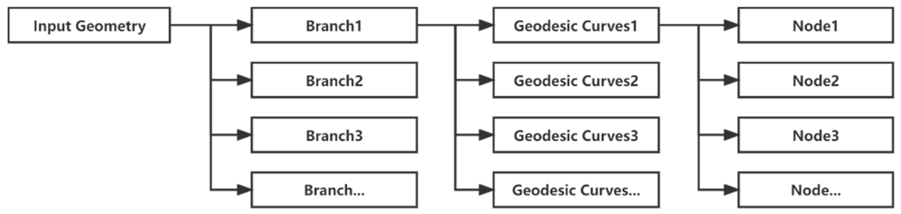
2.2. A Hierarchical Framework of the Printing Node Permutation
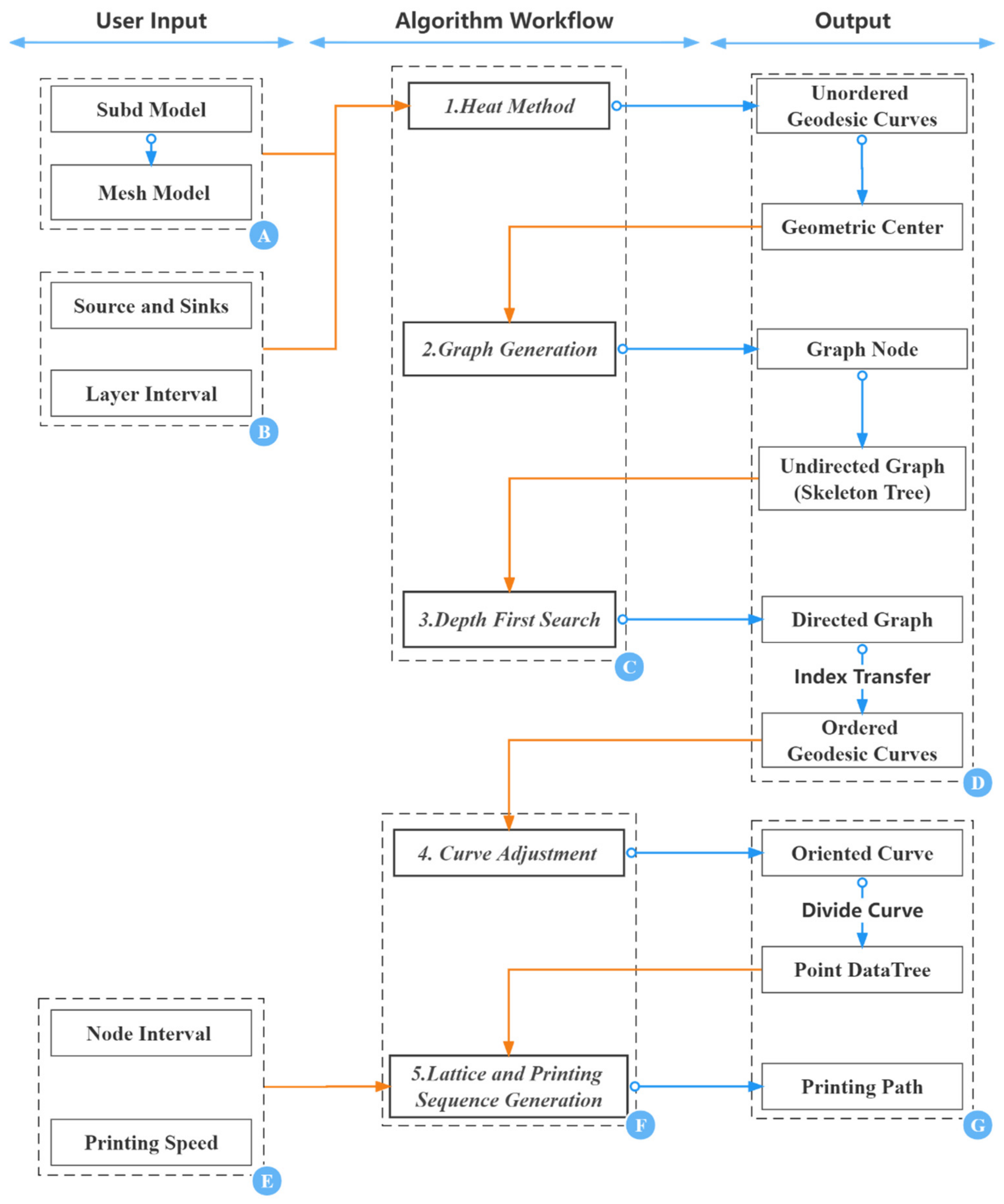
The RSP lattice structure consists of two fundamental components: the node and the strut. Since the entire structure is printed by moving the extrusion head from one node to the next, the printing node permutation determines the actual printing path. As a lattice structure might have a high number of disordered nodes, visiting these nodes individually incurs a substantial computing cost. As illustrated in Figure 2, we proposed a hierarchical framework of printing node permutation to ease the computing cost of the model.
This approach links the tree data structure (DataTree) to the 3DP BIBS, storing and visiting all the printing nodes needed in a printing process in a hierarchical framework. The nodes are first arranged into curve layers, which are then organized into branches, with each branch including a specific number of curve layers and each curve layer containing a specific number of nodes. Instead of visiting the nodes individually, our approach firstly determines the order of the branches B = b i , i = 1 , 2 , , B , then the permutation of the curve layers within each branch C = c i j , i = 1 , 2 , , B ; j = 1 , 2 , , C , and finally the permutation of the printing node in each curve layer N = n i j k , i = 1 , 2 , , B ; j = 1 , 2 , , C ; k = 1 , 2 , , N , allowing an efficient and feasible sequence of printing nodes to emerge from an otherwise complex geometry.

2.3. The Workflow

The proposed APPG approach incorporates three main phases: initial geometry design, algorithm workflow and printing design. This linear workflow system requires the user to set key algorithm parameters of the initial geometry design and printing design. The approach is classified into seven modules as shown in Figure 3A–G. The modules can be classified as follows:
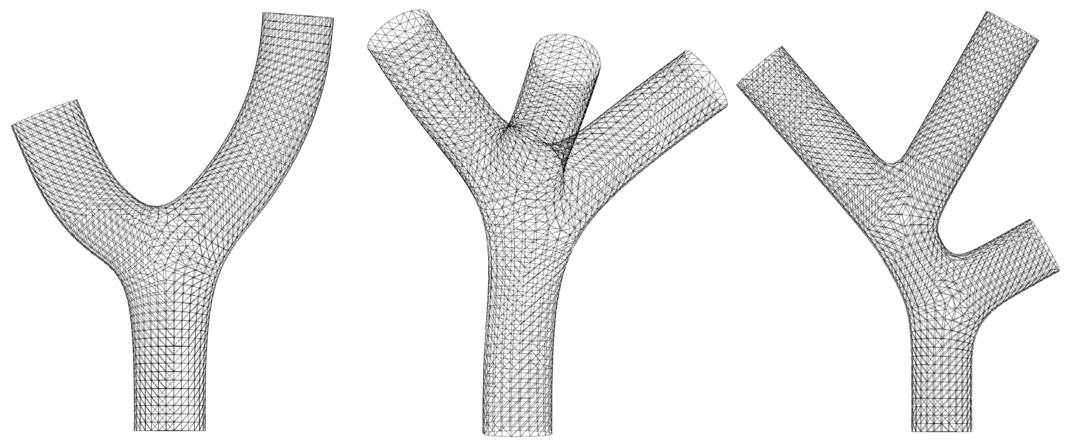
  • The user input of their initial model geometry. The user should use the SubD command multipipe in Rhinoceros to generate a branching geometry in SubD format and use the Quadremesh command to convert the SubD model into a mesh model (Section 3.1).
  • The user input for the heat method, including the source and sink classification and layer interval. The user should determine the layer interval and choose which mesh edge is the source and which is the sink according to the practical printing situation (Section 3.1).
  • Algorithms that generate the curve permutation as printing layers. The heat method is utilized to generate the geodesic curves and the graph method is used to determine the order of the curves (Section 3.2 and Section 3.3).
  • Output of different stages of the curve permutation including the graph to analyze the curves’ topological structure. The output of the heat method is unordered geodesic curves. To transform them into ordered curves, the graph method is applied (Section 3.2 and Section 3.3).
  • User input of the printing parameters, including the node interval and printing speed (Section 3.4 and Section 3.5).
  • Algorithms that generate the final printing node permutation. The curve adjustment includes the orientation adjustment and the seam adjustment, which provides the necessary foundation for the lattice generation (Section 3.4 and Section 3.5).
  • Output of different stages of the printing node permutation. The points embedded in the oriented curve are first stored in the DataTree, and then are used to generate the printing path for the lattice structure (Section 3.4 and Section 3.5).
These key algorithms, along with the inputs and outputs, are described in further detail in following sections.

3. Experiment

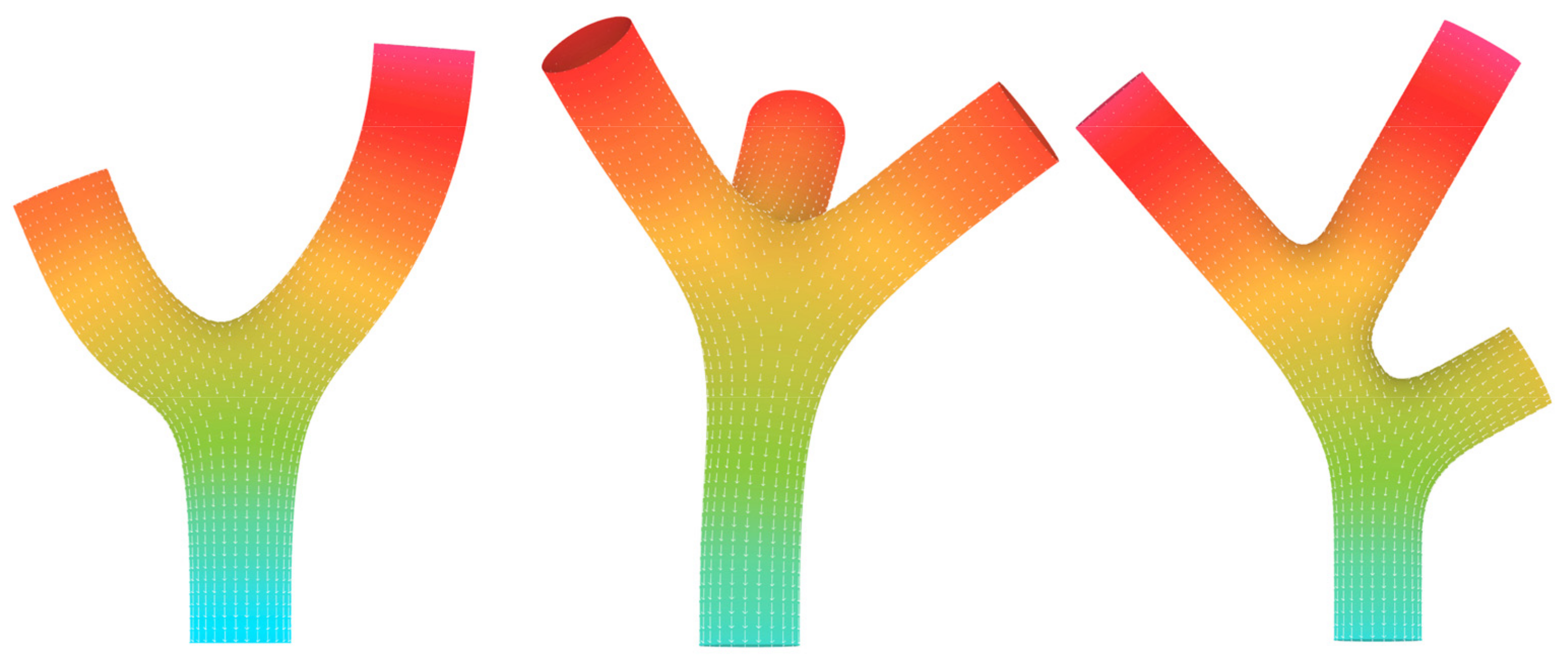
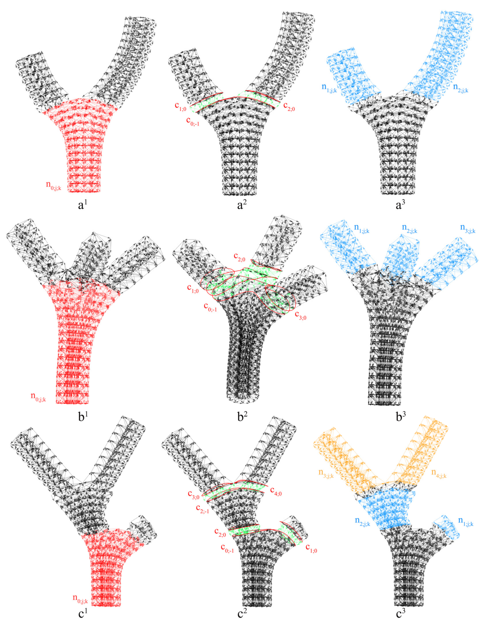
3.1. Geodesic Distance-Field-Based Slicing

To apply the geodesic distance field generation method, the start and end targets should be specified so that the interpolated geodesic curves can be formed between these targets. In the geodesic distance field, the start targets are set as the source and the end targets as the sinks. The source boundary should be perfectly perpendicular to the printing platform. As Figure 4 shows, Crane’s heat method [46] is applied to the triangulated mesh to calculate the temperature field for each, and each mesh’s texture coordinate is reset according to the temperature field. The source and sink boundary edges will fix the boundary values to produce a temperature field perpendicular to the boundaries. The reset texture coordinate is used to generate geodesic curves, and the input value curve interval decides the number of vertex groups containing mesh vertices that share the same range of y-values [36]. To equalize the distance between geodesic curves, the boundary values are swapped throughout the iteration, resulting in a greater number of geodesic curves on the longer branches and a smaller number on the shorter ones.

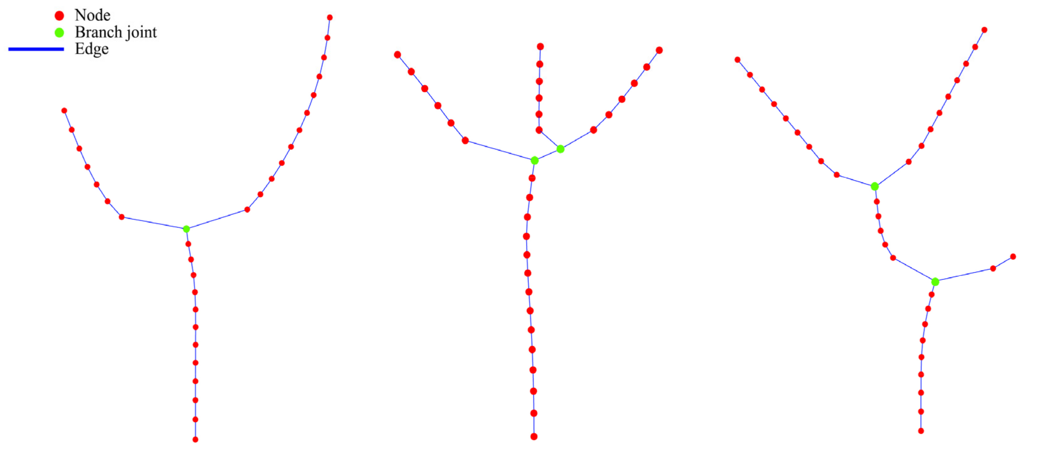
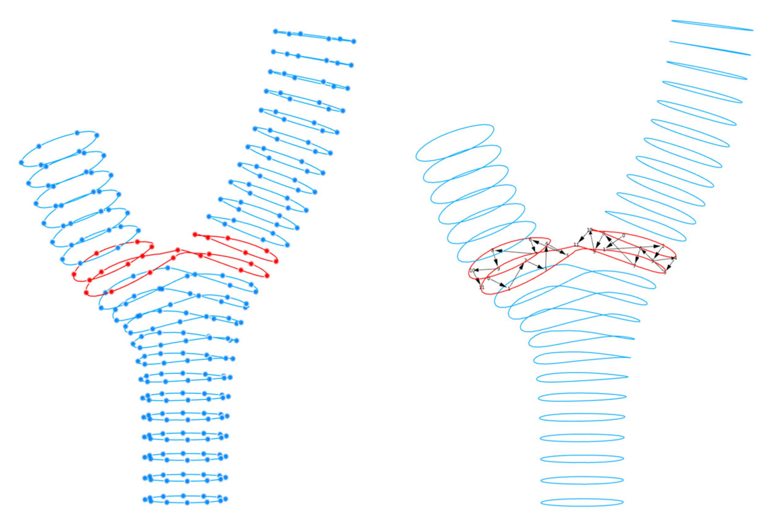
3.2. Graph Generation

The graph is a mathematical representation of a geometry’s topological type, consisting of a set of nodes (N) and the edges (E) interposed between them [47]. After decomposing the input geometry into geodesic curves, the algorithm generates an undirected graph (skeleton tree) [17] to illustrate the topological relationship among the curves. The corresponding pseudocode is given in Algorithm 1: Graph Generation.
Algorithm 1. Graph Generation
Input: List < Point3d > points
Output: int [,]adjacency Matrix; List < Line > Edge; List < Point3d > articulation Points
for pointi in List points;
  if pointj is adjacent to pointi
    adjacency Matrix [i, j] = 1 && adjacency Matrix [j, i] = 1
  end
end
for adjacency Matrix [i, j]
  if adjacency Matrix [i, j] = 1|| adjacency Matrix [j, i] = 1
    build Edge between pointi and pointj 
  end
end
for pointi in List points;
  if Edge[pointi] > = 3
    articulation Point = pointi
To represent the curve permutation and its topological structure with a graph, a point for each curve that is in proximity to its geometric center is calculated. Thus, the index data of the curves are transferred to the list of central points. There are two elements in the undirected graph: nodes and edges. Each central point in this undirected graph represents a node N g = n j g , j = 1 , 2 , , N g . If there is an edge between two nodes, then that means these two nodes are adjacent.
To establish this graph, firstly an adjacency matrix is created. Then, we initialize each member of its two-dimensional elements to 0. The line number and the column number of this matrix represent the index of the graph node N g . For example, if n 3 g and n 4 g are adjacent, then the matrix elements (3,4) and (4,3) will both equal to 1. By traversing this matrix, an edge is constructed between nodes when the matrix element that represents them is equal to 1. In the undirected graph, when node b is connected to node a by an edge and b’s z-value is larger than a’s, we call b an “upper node” and a is called a “lower node.” To verify that the graph is complete, we traverse each node to identify its upper and lower nodes. Figure 5 shows the undirected graph generated from the three prototypes.

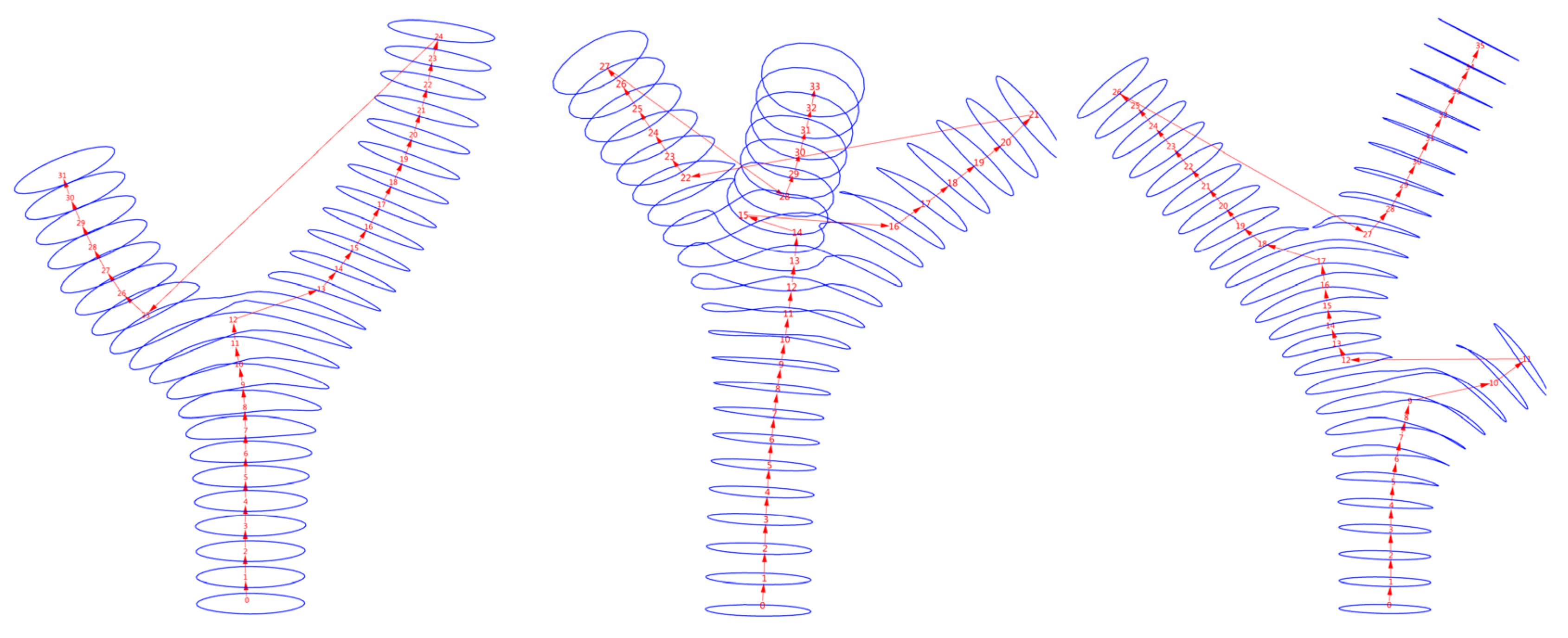
3.3. Graph Traversal

The goal of the graph traversal approach is to provide a single printing sequence that conforms to any branching geometry. Considering the printing process, the graph traversal method should satisfy the following two criteria:
Criteria 1: A printing sequence should conform to the graph; only if there is an edge between two nodes may these two nodes be printed continuously.
Criteria 2: A layer can only be printed if the previously printed layer is underneath it.
Layer-first search (LFS) and depth-first search (DFS) are two typical search techniques for undirected graphs. Both search algorithms conform to the two basic criteria previously outlined; however, their priorities differ. The LFS generates a printing sequence that considers the layer’s z-value first. The DFS generates a sequence in which one branch printing procedure should be completed before it prints the next. The DFS method provides a printing sequence that minimizes the extrusion head movement between necessary printing paths [17], so it is the one we adopted in our research. Our articulation of this algorithm is illustrated in Algorithm 2 and the result of its implementation on the prototypes is shown in Figure 6.
Algorithm 2. DFS Graph Traversal
Input: List < Point3d > points; int [,] adjacency Matrix; Point3d heatPoint;
Output: List < Point3d > DFS sorted points;
while (unsortedPoints.Count > 0)
  currentPoint = heatPoint
  currentPoint = currentPoint.findNext
  unsortedPoints.Remove(currentPoint)
  DFS sorted points.Add(currentPoint)
  if currentPoint.findNext == null
    unsortedPoints.findlowestPoint
    currentPoint = lowestPoint.findNext
    unsortedPoints.Remove(currentPoint)
    DFS sorted points.Add(currentPoint)
  end
end
static int findNext()
  for pointi in List points;
    if adjacency Matrix [i, j] = 1|| adjacency Matrix [j, i] = 1
      if pointj.Z > pointi.Z
        nextPoint = pointj 
      end
    end
  end
  return nextpointIndex
  end

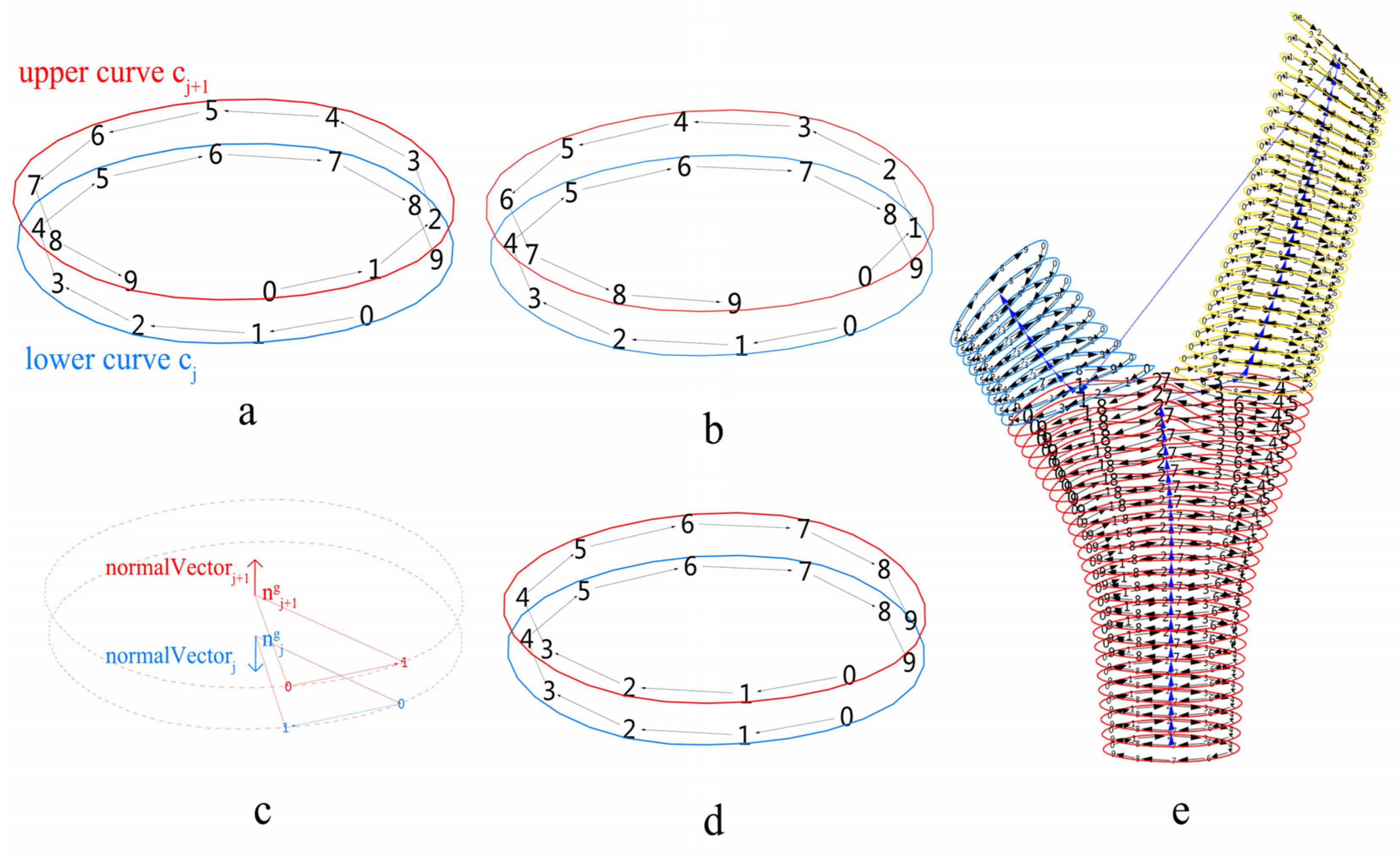
3.4. Curve Adjustment

Algorithm 2 gives the curve permutation. Nevertheless, as shown in Figure 7a, different curves will likely have distinct seams and orientations. To keep the printing path continuous, in one specific branch C = c i j , i = 1 , 2 , , B ; j = 1 , 2 , , C where the index i is identical, the seams of the upper curve c j + 1 and the lower curve c j should be as close as possible. To achieve this, the seam point of the lower curve c j is considered to be the reference point, and we utilize the ClosestPointAt Method to retrieve a point on the upper curve c j + 1 , which is the closest point to the reference point. Following this method, the curve index j and the reference point are updated. This procedure is continued until all of the curves in this branch are traversed, as shown in Figure 7e. To determine if a closed curve in the Euclidean coordinate system is oriented clockwise or counterclockwise, normal vectors are compared. As shown in Figure 7c, for curve c j , v e c t o r j 1 = n j g , n j k and v e c t o r j 2 = n j g , n j k + 1 are generated, as well as n o r m a l V e c t o r j = v e c t o r j 1 × v e c t o r j 2 . By calculating if n o r m a l V e c t o r j · n o r m a l V e c t o r j + 1 > 0 , we can determine if the upper curve c j + 1 shares the same orientation as the lower curve c j , otherwise the orientation of the upper curve c j + 1 should be flipped. This algorithm is demonstrated in Algorithm 3.
Algorithm 3. Curve Adjustment
Input: List < Curve > Geodesic Curves; DataTree < Point3d > Divide Points
Output: List < Curve > Oriented Curves
for (int i = 1; i < Geodesic Curves.Count; i++)
refPoint = Geodesic Curves [0].CurveSeam
refPoint = curves[i].ClosestPoint(refPoint)
curves[i].ChangeClosedCurveSeam(refPoint)
end
for (int i = 0; i < Geodesic Curves.Count −1; i++)
dotProduct = Vector3d.Multiply (normalVector[i], normalVector [i + 1])
if (dotProduct < 0)
Geodesic Curves [i + 1].Reverse()
   end

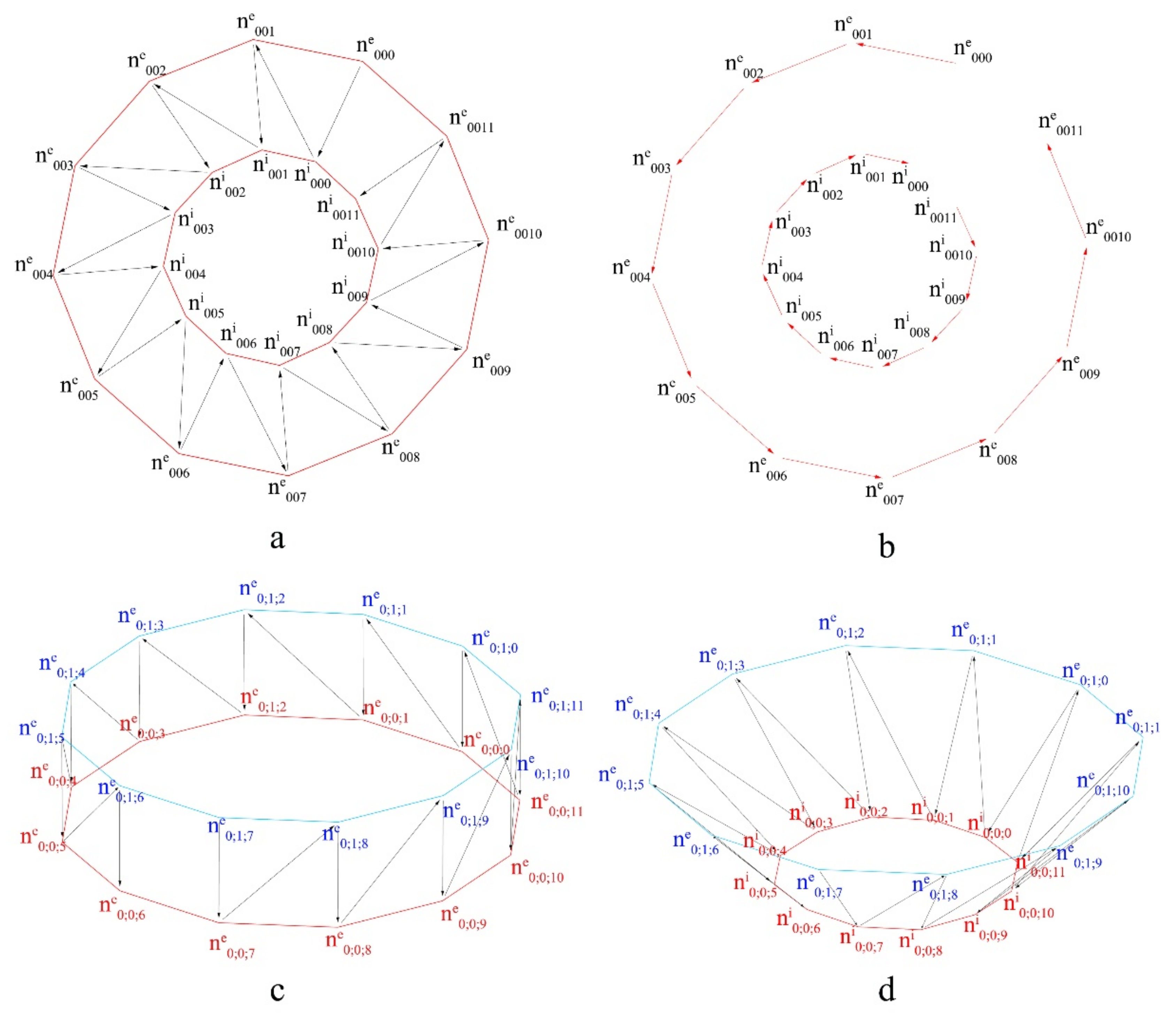
3.5. Lattice Generation

The above content illustrates how we obtained a hierarchical permutation of the data structure of the printing nodes N = n i j k , i = 1 , 2 , , B ; j = 1 , 2 , , C ; k = 1 , 2 , , N . In this section, the permutation of this data tree is employed to construct the lattice structure and its corresponding printing path. For nodes in the same layer, v e c t o r j k = n j g , n j k is generated, and each node moves along this vector for a printable distance (which in this case is 30 mm), forming a new node system with the same data structure as the formal nodes; we identify these two node systems by their relative positions, the formal nodes are labeled as internal N i = n i j k i , i = 1 , 2 , , B ; j = 1 , 2 , , C ; k = 1 , 2 , , N , and the nodes generated later are labeled as external; N e = n i j k e , i = 1 , 2 , , B ; j = 1 , 2 , , C ; k = 1 , 2 , , N . A weaving method is used to generate a path between N i and N e and between different layers of N i and N e .
Figure 8 illustrates the four strut types of the lattice structure, each of which is generated by a distinct weaving mechanism. The weaving method traverses two lists of data by a specific weaving pattern (in this situation the weaving pattern is {0;1}), which means the traversal procedure goes through two input streams, taking one element from the first list and then one element from the other list, combining two lists to generate a new one. Figure 8a,b shows the weaving structure that forms the horizontal zigzag printing path between n 0 ; 0 ; k i and n 0 ; 0 ; k e . Figure 8c illustrates the weaving structure between the upper layer n 0 ; 1 ; k e and the lower layer n 0 ; 0 ; k e , forming the vertical zigzag printing path; this type of weaving structure is constructed both internally and externally. Figure 8d represents the zigzag pattern between internal lower layer n 0 ; 0 ; k i and external upper layer n 0 ; 1 ; k e , constructing an inclined zigzag printing path that binds the internal and external structure tightly.
One issue with this weaving method is the branch joint articulation. At the joint of different branches, one base layer has to correspond with the multiple layers of the upper branches. In the case of two branches as shown in Figure 9, the top layer of the root n 0 ; 12 ; k e is connected to two upper layers n 1 ; 0 ; k e and n 2 ; 0 ; k e . The correspondence of the nodes in these layers should be articulated first before the lattice generation method can be implemented.
If two branches share the same root, then the node count k of each layer in these two branches should be half of that in the root. At the first layer of these two branches, the ClosestPointAt Method is used to find best-corresponding nodes in the base layer. Each node of n 1 ; 0 ; k e and n 2 ; 0 ; k e has one correspondent node and index, and these correspondent nodes and their indices serve as these two branches’ true base layers and are used to generate the lattice for the joint of the branches, as shown in Figure 9.

4. Results

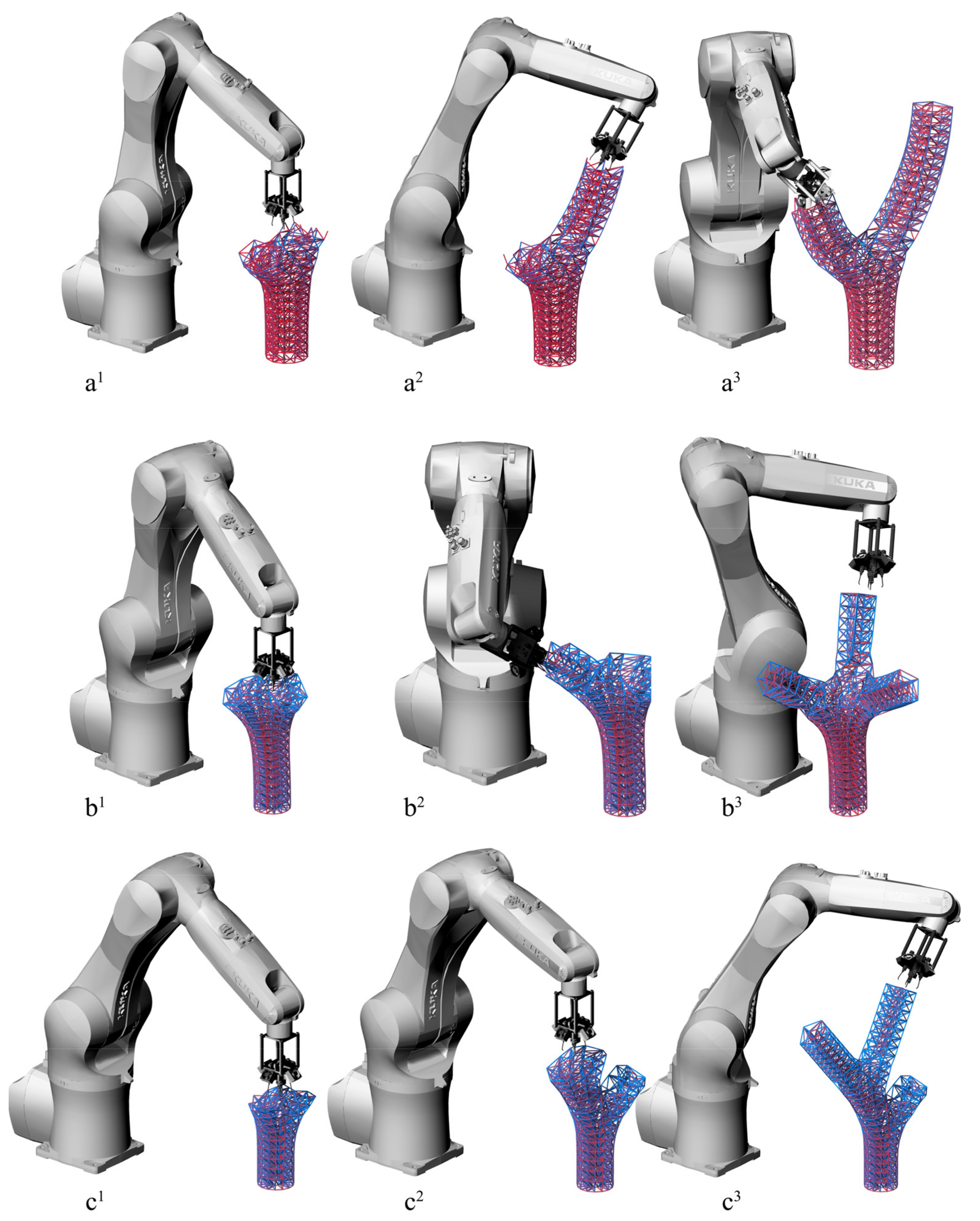
4.1. Printing Simulation Setup

The printing procedure simulation was configured on the Rhinoceros platform using the KUKA|PRC plugin. In this example, a KUKA Agilus KR6 R900 Robot was adopted. The sizes of the input prototypes were adjusted to correspond with the robot arm’s operational capability. The geodesic contours were generated using the tool’s printable strut length, which ranges from 10 mm to 80 mm. The linear movement command was utilized to convert the points our algorithm generated to the robot’s movement procedure, which in this case accounted for the size and offset of the extrusion head. The extrusion head was configured to move at a rate of 0.03 m/s in accordance with the practical printing procedure. Printing speed was the key parameter that affected the overall printing time, as analyzed below.

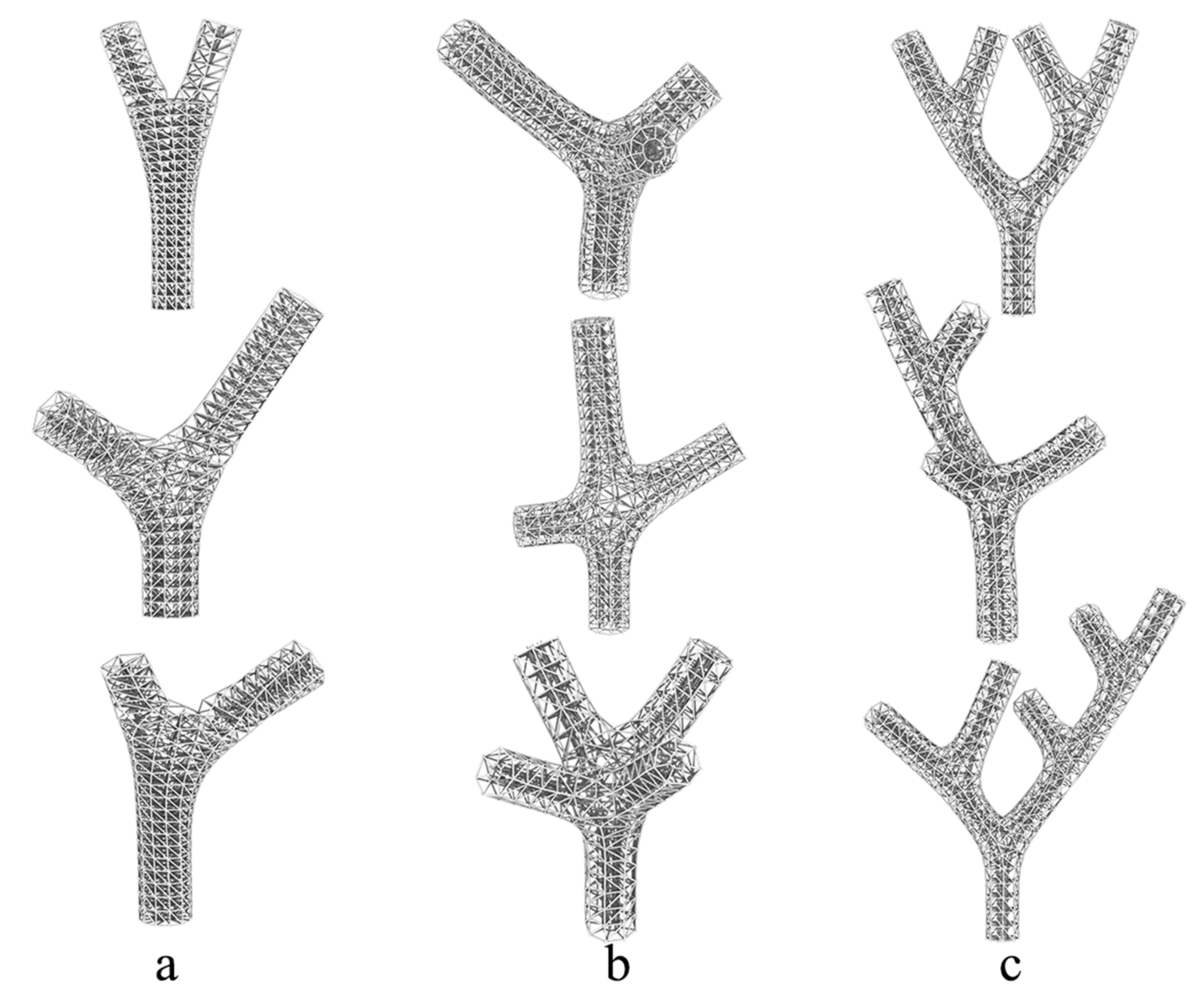
4.2. Prototypes Implementation

The final results of the lattice generation and the printing node permutation of the aforementioned three prototypes using our approach are illustrated in Figure 10. The approach was optimal for these basic types: two branch geometry, multi-branch geometry and multi-level-branch geometry. These three prototypes demonstrate the fundamental elements of tree-like geometries and can be combined to form more complicated geometries that belong to this topological type.
Figure 10a1–c1 emphasize the root formulation of these prototypes in red, and a2–c2 demonstrate typical branch joint design solutions for various prototypes.
There are three geodesic curves for generating the branch joint in the two-branch prototype labeled a2. C0; −1 is the last curve of the root branch; C1;0 and C2;0 are the first curves of the first and second branch, respectively.
In the multi-branch prototype labeled as b2, there are two subdivisions: C1; 0 and C2; 0 are initially divided from C3;0, and then they are separated from each other to form their own branches.
For the multi-level branch prototype labeled as c2, there are two levels of branch joints: the first level is generated from the curves C0; −1, C1;0 and C2; 0, and the second level is generated from C2; −1, C3; 0 and C4; 0.
All the branch joints conform to the lattice structure of the root branches to which they connect, and the printing node permutations are appropriately organized to maintain rigidity. Figure 10a3–c3 illustrate the branches highlighted in blue and sub-branches highlighted in yellow.
In addition to the three prototypes proposed, the APPG approach is able to be implemented on various branching geometries. Figure 11 demonstrates the possible extensions of the three original prototypes: (a) two-branch geometry prototype, (b) multi-branch geometry prototype, and (c) multi-level-branch geometry prototype. Figure 11 depicts these examples with varying branching angles, lengths, branch numbers, and branch levels. They provide confirmation of the solution’s general applicability.

4.3. Fabrication Expenses

Table 1 lists the fabrication expenses of the basic prototype with the height of 700 mm. Here they are compared with other frontier algorithms including Li’s support-free planar printing algorithm (SFP) [17] and Huang’s RSP algorithm (SAMP) [45], both implemented on two-branch structures. The computational time (CT) of each prototype revealed that our algorithm was the most time-efficient, requiring only 2.4 s to calculate the permutation of 2628 printing nodes. The SAMP required 35 s to calculate the permutation of 91 printing nodes, which is clearly unsuitable for large-scale printing. Although the SFP method could also deal with a high number of nodes, the planar printing method resulted in a redundant printing path length of 49,765 mm, which limits the scale of its production.

4.4. Printing Validation

Figure 12 demonstrates the printing process simulation of the three prototypes, each of which features distinct branches and corresponding printing orientations. Printing orientation is a key parameter influencing the quality of the printed products because it confronts the following issues: (a) materials being extruded that are still at their glass transition temperature will be unexpectedly deformed by the pressure from the end-effector; (b) there might be a collision between the end-effector and the solid material that has been extruded; (c) the robot arm motion should be kept smooth. Optimizing the printing orientation while keeping a modest angle with the direction of gravity and adhering to the normal vector direction of distinct layers is the optimal solution for these problems. To achieve that, the directed graph discussed earlier was employed to generate the printing orientation. When the angle between the printing orientation and gravity direction exceeded 30 degrees, it was adjusted to be 30 degrees, which is the optimal angle determined empirically through formal experimentation.
In Figure 12, the three protypes are labeled a, b and c. When calculating the angle between struts and horizontal plane, we utilized a red-to-blue gradient to indicate the angle’s value. As the angle increased, the color gradually moved from red to blue. As shown in Figure 12, the struts in the root branches typically have a relatively modest angle, whereas larger angles can be found in upper branches’ struts. These angle transitions were determined by the orientation of the branch boundary curve. In our method, the extrusion head direction was adjusted to accommodate this transition in order to create a successfully printed outcome.

5. Summary and Future Research

This research presents a cutting-edge attempt to implement robotic spatial printing (RSP) on branching geometries. The research proposes a novel automated printing path generation (APPG) approach containing a new hierarchical framework of data and a workflow of algorithms. Due to the topologically difficult and computationally expensive nature of branching geometries, related studies have been limited in small-scale layer-based printing. Studies on large-scale RSP are rarely found. The hierarchical framework presented in this paper addresses this problem by combining the highly ordered branching structure’s node permutation with the DataTree structure in the Grasshopper plugin. Therefore, it is possible to print branching geometry by extruding materials directly in 3D space.
Along with the hierarchical system, the simulation results are presented with a comparison of computational cost that demonstrates the efficiency of the APPG approach. This enables it to be implemented on permutations with a large number of disordered nodes, thereby improving the large-scale RSP procedure in the construction industry. This paper also introduces a useful analytical tool for topological analysis of input geometries, including undirected graph (skeleton tree) generation and branching joint articulation. The related codes are packaged into an easy-to-use GHA file.
The branching geometry prototypes proposed in this paper are based on topology theory. These prototypes and their combinations represent a vast library of geometries and indicate the algorithm’s potential to be used to generate an appropriate printing path for more complex branching geometries that have been topologically optimized. Even still, there are limitations to this study. A few areas that should be expanded or investigated further are outlined as follows.
Input geometries: The algorithm provided in this study does not take into account all of the topological types that can be printed; instead, it focuses on the branching geometries known as “Trees” in graph theory, which is an undirected graph with no torus. When the printing procedure encounters input geometries with a torus, the printing path should be modified. The printing orientation at the torus’s joint may still present significant challenges.
The combination of APPG with a mechanical optimization method such as topology optimization [48] and 3D graphic statics [49]: As one of the conventional 3D printing configurations, RSP is also suitable for the manufacture of topology optimization or 3D graphic statics results. To fully enable this method in combination with topology optimization, input geometries should be further extended as mentioned above. It is critical to consider how to integrate these two methods in order to achieve a more efficient computation procedure and a more efficient output for both mechanical properties and printing procedure.

Author Contributions

Conceptualization, X.S. and D.W.; methodology, X.S., Y.L., T.K.P. and D.W; software, Y.L. and H.Z.; resources, T.K.P.; writing—original draft preparation, Y.L.; writing—review and editing, T.K.P., W.C. and D.W.; visualization, Y.L. and H.Z.; supervision, D.W. and W.C.; project administration, X.S.; funding acquisition, X.S. and W.G. All authors have read and agreed to the published version of the manuscript.

Funding

This research was funded by (the Key Technology Research and Development Program of Shandong) grant number (2019GSF110004), and (the research program of National Natural Science Foundation of China Youth Science Fund Project) grant number (52008224).

Institutional Review Board Statement

Not applicable.

Informed Consent Statement

Not applicable.

Data Availability Statement

Not applicable.

Acknowledgments

We are very grateful to Haining Zhou and Kang Bi (Faculty of Environmental Engineering, The University of Kitakyushu, Japan) for their generous advice and help in the research process, as well as the DAMlab (Digital Architecture and Manufacture Laboratory) in Qingdao University of Technology for providing highly qualified equipment support during this study.

Conflicts of Interest

The authors declare no conflict of interest.

References

  1. Li, H.-J.; Wang, Z.-Z.; LI, Z.-C. Reliability and Sensitivity analysis of dendriform structure. Int. J. Space Struct. 2013, 28, 75–86. [Google Scholar]
  2. Peng, X. Structural Topology Optimization Method for Morphogenesis of Dendriforms. Open J. Civ. Eng. 2016, 6, 526–536. [Google Scholar] [CrossRef] [Green Version]
  3. Kripakaran, P.; Gupta, A.; Baugh, J.W. A novel optimization approach for minimum cost design of trusses. Comput. Struct. 2007, 85, 1782–1794. [Google Scholar] [CrossRef]
  4. Daminabo, S.C.; Goel, S.; Grammatikos, S.A.; Nezhad, H.Y.; Thakur, V.K. Fused deposition modeling-based additive manufacturing (3D printing): Techniques for polymer material systems. Mater. Today Chem. 2020, 16, 100248. [Google Scholar] [CrossRef]
  5. Yuan, P.F.; Beh, H.S.; Yang, X.; Zhang, L.; Gao, T. Feasibility study of large-scale mass customization 3D printing framework system with a case study on Nanjing Happy Valley East Gate. Front. Archit. Res. 2022, 11, 670–680. [Google Scholar] [CrossRef]
  6. Nieto, D.M.; López, V.C.; Molina, S.I. Large-format polymeric pellet-based additive manufacturing for the naval industry. Addit. Manuf. 2018, 23, 79–85. [Google Scholar]
  7. Nadal, A.; Cifre, H.; Pavón, J.; Liébana, Ó. Material use optimization in 3D printing through a physical simulation algorithm. Autom. Constr. 2017, 78, 24–33. [Google Scholar] [CrossRef]
  8. Weeger, O.; Kang, Y.S.B.; Yeung, S.-K.; Dunn, M.L. Optimal Design and Manufacture of Active Rod Structures with Spatially Variable Materials. 3d Print. Addit. Manuf. 2016, 3, 204–215. [Google Scholar] [CrossRef]
  9. Dong, G.; Tang, Y.; Li, D.; Zhao, Y.F. Design and optimization of solid lattice hybrid structures fabricated by additive manufacturing. Addit. Manuf. 2020, 33, 101116. [Google Scholar] [CrossRef]
  10. Gao, W.; Zhang, Y.; Ramanujan, D.; Ramani, K.; Chen, Y.; Williams, C.B.; Wang, C.C.L.; Shin, Y.C.; Zhang, S.; Zavattieri, P.D. The status, challenges, and future of additive manufacturing in engineering. Comput.-Aided Des. 2015, 69, 65–89. [Google Scholar] [CrossRef]
  11. Masood, S.H. Intelligent rapid prototyping with fused deposition modelling. Rapid Prototyp. J. 1996, 2, 24–33. [Google Scholar] [CrossRef]
  12. Tamburrino, F.; Graziosi, S.; Bordegoni, M. The Design Process of Additively Manufactured Mesoscale Lattice Structures: A Review. J. Comput. Inf. Sci. Eng. 2018, 18, 040801. [Google Scholar] [CrossRef]
  13. Wu, J.; Wang, C.C.L.; Zhang, X.; Westermann, R. Self-supporting rhombic infill structures for additive manufacturing. Comput.-Aided Des. 2016, 80, 32–42. [Google Scholar] [CrossRef]
  14. Lee, M.; Fang, Q.; Cho, Y.; Ryu, J.; Liu, L.; Kim, D.-S. Support-free hollowing for 3D printing via Voronoi diagram of ellipses. Comput.-Aided Des. 2018, 101, 23–36. [Google Scholar] [CrossRef]
  15. Keating, S.; Oxman, N. Compound fabrication: A multi-functional robotic platform for digital design and fabrication. Robot. Comput.-Integr. Manuf. 2013, 29, 439–448. [Google Scholar] [CrossRef]
  16. Dai, C.; Wang, C.C.L.; Wu, C.; Lefebvre, S.; Fang, G.; Liu, Y.-J. Support-free volume printing by multi-axis motion. ACM Trans. Graph. 2018, 37, 134. [Google Scholar] [CrossRef] [Green Version]
  17. Li, Y.; Tang, K.; He, D.; Wang, X. Multi-Axis Support-Free Printing of Freeform Parts with Lattice Infill Structures. Comput.-Aided Des. 2021, 133, 102986. [Google Scholar] [CrossRef]
  18. Xu, K.; Li, Y.; Chen, L.; Tang, K. Curved layer based process planning for multi-axis volume printing of freeform parts. Comput.-Aided Des. 2019, 114, 51–63. [Google Scholar] [CrossRef]
  19. Wang, R.L.Z.; Sparks, T.; Liou, F. Large-Scale Deposition System by an Industrial Robot (I): Design of Fused Pellet Modeling System and Extrusion Process Analysis. 3d Print. Addit. Manuf. 2016, 3, 39–47. [Google Scholar] [CrossRef]
  20. Nomani, J.; Wilson, D.; Paulino, M.; Mohammed, M.I. Effect of layer thickness and cross-section geometry on the tensile and compression properties of 3D printed ABS. Mater. Today Commun. 2020, 22, 100626. [Google Scholar] [CrossRef]
  21. Roschli, A.; Gaul, K.T.; Boulger, A.M.; Post, B.K.; Chesser, P.C.; Love, L.J.; Blue, F.; Borish, M. Designing for Big Area Additive Manufacturing. Addit. Manuf. 2019, 25, 275–285. [Google Scholar] [CrossRef]
  22. Trejo, E.M.; Jimenez, X.; Billah, K.M.M.; Seppala, J.; Wicker, R.; Espalin, D. Compressive deformation analysis of large area pellet-fed material extrusion 3D printed parts in relation to in situ thermal imaging. Addit. Manuf. 2020, 33, 101099. [Google Scholar]
  23. Nguyen, J.; Park, S.-I.; Rosen, D.W.; Folgar, L.; Williams, J. Conformal lattice structure design and fabrication. In Proceedings of the 2012 International Solid Freeform Fabrication Symposium, Austin, TX, USA, 6–8 August 2012. [Google Scholar]
  24. Liu, S.; Li, Y.; Li, N. A novel free-hanging 3D printing method for continuous carbon fiber reinforced thermoplastic lattice truss core structures. Mater. Des. 2018, 137, 235–244. [Google Scholar] [CrossRef]
  25. Xu, B.; Yin, S.; Wang, Y.; Li, H.; Zhang, B.; Ritchie, R.O. Long-fiber reinforced thermoplastic composite lattice structures: Fabrication and compressive properties. Compos. Part A Appl. Sci. Manuf. 2017, 97, 41–50. [Google Scholar] [CrossRef]
  26. Tam, K.-M.; Marshall, D.J.; Gu, M.; Kim, J.; Huang, Y.; Lavallee, J.; Mueller, C.T. Fabrication-aware structural optimisation of lattice additive-manufactured with robot-arm. Int. J. Rapid Manuf. 2018, 7, 120–168. [Google Scholar] [CrossRef]
  27. Chen, Z.; Zhang, L.; Yuan, P.F. Innovative design approach to optimized performance on large-scale robotic 3d-printed spatial structure. 2019. Intelligent & Informed. In Proceedings of the 24th International Conference of the Association for Computer-Aided Architectural Design Research in Asia (CAADRIA) 2019, New Zealand, 15–18 April 2019; Volume 2, pp. 451–460. [Google Scholar]
  28. Yuan, P.F.; Meng, H.; Yu, L.; Zhang, L. Robotic Multi-dimensional Printing Based on Structural Performance. In Robotic Fabrication in Architecture, Art and Design 2016; Springer: Cham, Switzerland, 2016; pp. 92–105. [Google Scholar]
  29. Mueller, S.; Im, S.; Gurevich, S.; Teibrich, A.; Pfisterer, L.; Guimbretière, F.; Baudisch, P. WirePrint. In Proceedings of the 27th Annual ACM Symposium on User Interface Software and Technology, Honolulu, HI, USA, 5–8 October 2014; pp. 273–280. [Google Scholar]
  30. Tam, K.-M.M.; Mueller, C.T. Additive Manufacturing Along Principal Stress Lines. 3d Print. Addit. Manuf. 2017, 4, 63–81. [Google Scholar] [CrossRef]
  31. Xiao, X.; Joshi, S. Process planning for five-axis support free additive manufacturing. Addit. Manuf. 2020, 36, 101569. [Google Scholar] [CrossRef]
  32. Xiao, X.; Xiao, H. Autonomous Robotic Feature-Based Freeform Fabrication Approach. Materials 2021, 15, 247. [Google Scholar] [CrossRef]
  33. Huang, Y.; Garrett, C.R.; Mueller, C.T. Automated sequence and motion planning for robotic spatial extrusion of 3D trusses. Constr. Robot. 2018, 2, 15–39. [Google Scholar] [CrossRef] [Green Version]
  34. Xiao, X.; Joshi, S. Decomposition and Sequencing for a 5-Axis Hybrid Manufacturing Process. In Volume 1: Additive Manufacturing; Advanced Materials Manufacturing; Biomanufacturing; Life Cycle Engineering; Manufacturing Equipment and Automation; American Society of Mechanical Engineers: New York, NY, USA, 2020. [Google Scholar]
  35. Zhang, J.; Ruan, J.; Liou, F. A process planning strategy for multi-axis hybrid manufacturing process. Int. J. Rapid Manuf. 2013, 3, 130–153. [Google Scholar] [CrossRef]
  36. Crane, K.; Weischedel, C.; Wardetzky, M. The heat method for distance computation. Commun. ACM 2017, 60, 90–99. [Google Scholar] [CrossRef]
  37. Belyaev, A.G.; Fayolle, P.-A. On Variational and PDE-Based Distance Function Approximations. Comput. Graph. Forum 2015, 34, 104–118. [Google Scholar] [CrossRef]
  38. Nguyen, T.; Karciauskas, K.; Peters, J. C(1) finite elements on non-tensor-product 2d and 3d manifolds. Appl. Math. Comput. 2016, 272, 148–158. [Google Scholar] [CrossRef] [PubMed]
  39. Romero-Carrillo, P.; Torres-Jimenez, E.; Dorado, R.; Díaz-Garrido, F. Analytic construction and analysis of spiral pocketing via linear morphing. Comput.-Aided Des. 2015, 69, 1–10. [Google Scholar] [CrossRef]
  40. Kout, A.; Müller, H. Quantitative improvement of tool impact paths defined by isolines of scalar functions on triangular mesh workpiece surfaces. Int. J. Adv. Manuf. Technol. 2013, 70, 237–255. [Google Scholar] [CrossRef]
  41. Chuang, J.-J.; Yang, D.C.H. A laplace-based spiral contouring method for general pocket machining. Int. J. Adv. Manuf. Technol. 2006, 34, 714–723. [Google Scholar] [CrossRef]
  42. Mitropoulou, I.; Bernhard, M.; Dillenburger, B. Print Paths Key-framing. In Symposium on Computational Fabrication; ACM Digtal Library: New York, NY, USA, 2020; pp. 1–10. [Google Scholar]
  43. Hack, N.; Lauer, W.V. Mesh-mould: Robotically fabricated spatial meshes as reinforced concrete formwork. Archit. Des. 2014, 84, 44–53. [Google Scholar] [CrossRef]
  44. Soler, V.; Retsin, G.; Garcia, M.J. A generalized approach to non-layered fused filament fabrication. ACADIA Proc. 2017. [Google Scholar] [CrossRef]
  45. Huang, Y.; Zhang, J.; Hu, X.; Song, G.; Liu, Z.; Yu, L.; Liu, L. FrameFab: Robotic Fabrication of Frame Shapes. ACM Trans. Graph. 2016, 35, 1–11. [Google Scholar] [CrossRef]
  46. Crane, K.; Weischedel, C.; Wardetzky, M. Geodesics in heat. ACM Trans. Graph. 2013, 32, 152. [Google Scholar] [CrossRef] [Green Version]
  47. Vecchio, F.; Miraglia, F.; Rossini, P.M. Connectome: Graph theory application in functional brain network architecture. Clin. Neurophysiol. Pract. 2017, 2, 206–213. [Google Scholar] [CrossRef] [PubMed]
  48. Xie, Y.M.; Steven, G.P. Basic evolutionary structural optimization. In Evolutionary Structural Optimization; Springer: Berlin/Heidelberg, Germany, 1997; pp. 12–29. [Google Scholar]
  49. Bolhassani, M.; Akbarzadeh, M.; Mahnia, M.; Taherian, R. On Structural Behavior of a Funicular Concrete Polyhedral Frame Designed by 3D Graphic Statics. Structures 2018, 14, 56–68. [Google Scholar] [CrossRef]
Figure 1. Three prototypes of input meshes.
Buildings 12 02247 g001
Figure 2. Hierarchical framework of printing node permutation.
Buildings 12 02247 g002
Figure 3. Overview of the workflow.
Buildings 12 02247 g003
Figure 4. Temperature field of three prototypes.
Buildings 12 02247 g004
Figure 5. Undirected graph of the three prototypes.
Buildings 12 02247 g005
Figure 6. Depth-first traversal.
Buildings 12 02247 g006
Figure 7. Curve Adjustment: (a) original different seams and orientations between upper and lower curve; (b) modified seams and orientations with different curve normalVector; (c) illustration of curve’s normalVector; (d) corrected seams and orientations between upper and lower curve; (e) traversed for all curves in this branch.
Buildings 12 02247 g007
Figure 8. Lattice Generation: (a) horizontal zigzag printing; (b) horizontal printing; (c) vertical zigzag printing; (d) zigzag pattern between internal lower layer and external upper layer.
Buildings 12 02247 g008
Figure 9. Branch Articulation.
Buildings 12 02247 g009
Figure 10. Prototype Lattice Generation: (a) two-branch geometry; (b) multi-branch geometry; (c) multi-level-branch geometry.
Buildings 12 02247 g010
Figure 11. Examples of possible inputs and their generated lattice: (a) two-branch geometry; (b) multi-branch geometry; (c) multi-level-branch geometry.
Buildings 12 02247 g011
Figure 12. Printing process simulation: (a) two-branch geometry; (b) multi-branch geometry; (c) multi-level-branch geometry.
Buildings 12 02247 g012
Table 1. Data for a printing simulation: computational time (CT), path length (Lpath), unit height printing time (Timeunit), number of layers (Nlayer), number of nodes (Nnode), and average strut length ( L s t r u t ¯ ). Results are shown for Li’s support-free printing algorithm (SFP) [17], Huang’s sequence and motion planning algorithm (SAMP) [33], and the APSP method presented in this paper.
FactorCT (s)Lpath (mm)Timeunit (s)Nlayer Nnode
InputAPSPSFPSAMPAPSPSAMPAPSPSFPSAMPAPSPSFPSAMPAPSPSFPSAMP
Prototype2.43335106,73949,765507855311458262817,14891
Publisher’s Note: MDPI stays neutral with regard to jurisdictional claims in published maps and institutional affiliations.

