Article

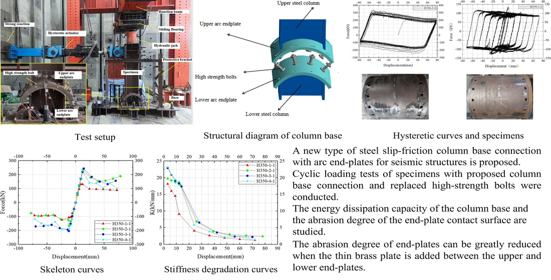
Experimental Study on Seismic Behavior of Steel Column Base Connections with Arc End-Plates Slip-Friction

1
School of Urban Construction, Wuhan University of Science and Technology, No.947 Qingshan Heping Road, Wuhan 430081, China
2
Hubei Provincial Engineering Research Center of Urban Regeneration, Wuhan University of Science and Technology, No.947 Qingshan Heping Road, Wuhan 430081, China
3
School of Civil and Hydraulic Engineering, Huazhong University of Science and Technology, No.1037 Luoyu Road, Wuhan 430074, China
*
Author to whom correspondence should be addressed.
Buildings 2022, 12(11), 2012; https://doi.org/10.3390/buildings12112012
Submission received: 25 October 2022 / Revised: 8 November 2022 / Accepted: 15 November 2022 / Published: 17 November 2022
(This article belongs to the Special Issue Prefabricated and Modular Steel Structures)

Abstract

:
This paper proposes a new type of steel slip-friction column base connections with arc end-plates. Two arc end-plates of the steel column base, which can slide between each other to some extent, were set at the position where the column base is subject to plastic deformation. Thus, the sliding-friction energy dissipation between the arc end-plates can effectively minimize or eliminate the energy dissipation of the traditional column base connections. Cyclic loading tests were conducted to study the hysteretic performance and energy consumption performance of the proposed connections. Considerations have been given to different axial compression ratios, Belleville springs (Bes), brass plates, and horizontal loading protocols. The test results show no obvious deformation or damage during the radial cyclic loading test. The curve shape of the test measurement approximates a parallelogram, showing good force performance. The proposed connections with the increasing axial compression force can increase the energy dissipation ability and load-carrying capacity. Therefore, the proposed connection has perfect seismic behavior.

Graphical Abstract

1. Introduction

The steel column base is a vulnerable part of steel structures. In the 1994 Northridge Earthquake [1] in the United States and the 1995 Hanshin Earthquake [2] in Japan, quite a lot of the buildings were damaged or collapsed due to large deformation or damage to the steel column bases. Repairing, dismantling, or even terminating the use of these structures will cause huge losses, economic losses, and negative social impacts. In order to reduce structural damage and the secondary effects of earthquakes, many scholars have begun to focus on the seismic performance of steel column bases. Suzuk et al. [3] carried out tests on conventional column base joints and showed that flexural deformation of conventional column base joints leads to axial shortening of the steel column which in turn leads to a reduction in the bending capacity and axial load-carrying capacity of the steel column. It is therefore necessary to control the damage to the column base connection.
Friction connection is a low-damage connection, SFC (Symmetry Friction Connect) and AFC (Asymmetric Friction Connect) were originally used in beam-column connections [4,5]. By providing friction dampers at the joint instead of the traditional rigid connection, seismic energy is dissipated and damage to the main structure is reduced [6,7]. In recent years, the use of friction mechanisms for column base connections has received attention from scholars. Borzouie et al. [8,9] designed a sliding asymmetric friction connection. Tests have demonstrated that the frictional column base connection shows no significant strength degradation and can achieve low loss performance of the main structure, which can be widely used in seismic-resistant structures. Liu et al. [10] conducted an experimental study of a new type of elastic rocking (IRR) column with replaceable steel seam dampers. The experimental results showed that the IRR column had good ductility and hysteretic properties, with no significant strength and stiffness degradation, and that the damage was mainly to the dampers. The steel seam dampers can be repaired quickly and the performance after the repair is essentially the same as before the repair. Freddi et al. [11,12] proposed a swaying column base connection with a friction device, which is connected to the foundation by the friction device, and the friction device dissipates energy during the column swaying process so that the main body of the column base remains undamaged. Elettore et al. [13,14] proposed a self-centered lossless column base connection, where the steel column slides. The frictional load generated between the column end and the friction plate dissipates energy to achieve a low and lossless structure. Li et al. [15,16] proposed a new sliding frictional column base connection that achieves a lossless performance of the structure by replacing the energy dissipated by the conventional column base connection with the frictional dissipation between the curved end plates at the column end.
Based on the previous studies [15,16], an innovative kind of steel column base connection with arc end-plates slip-friction was proposed (in Figure 1) to achieve damage-free energy dissipation. This column base connection is composed of the steel column, upper and lower arc end-plates, high-strength bolts, top plate, and base plate. Among them, the upper steel column is welded with the upper arc end-plate and the top plate. The lower steel column is welded with the lower arc end-plate and the base plate, the upper and lower arc end-plates are connected using high-strength bolts. The pre-compression between the upper and lower arc end-plates is produced by applying a pre-tension force to the high-strength bolts. Oblong bolt holes are set in the upper arc end-plate so that the upper part of the connection can rotate about the oblong holes. Circular bolt holes are made in the lower arc end-plate. Because the arc end-plate of the connection is set at the position where the plastic hinge is easy to appear at the bottom of the column. The seismic energy is dissipated by rotating sliding friction instead of consuming the yield energy of traditional members. The main structure remains undamaged, so as to achieve the design goal of undamaged energy consumption. The maximum rotation angle of the connection can be controlled by the size of the oblong bolt hole on the upper arc end-plate. Therefore, the prominent advantage of the proposed connection is that when the arc end-plate of the connection does not slip, the connection is equivalent to the traditional steel column. However, when the connected arc end-plate slides, the seismic energy is dissipated by arc end-plates and the rotational friction between the arc end-plates and bolts. The sliding-friction energy dissipation is used to replace the energy dissipation caused by the material yielding of the traditional connection. The steel column base connections with arc end-plates slip-friction proposed in this paper is a non-damage connection mode applied by SHJ to the column base, the axial compression force can effectively increase the friction force between the arc end-plates of the column base slip friction connection proposed in this paper.
This paper describes an experimental research plan, including eight groups of tests of four full-scale specimens under two loading systems, to study the effects of axial pressure, Bes, and brass plate on the seismic behavior of steel column base connections with arc end-plates slip-friction.
This paper answers the following questions through eight groups of experimental results:
1. What is the seismic performance of steel column base connections with arc end-plates slip-friction under different parameters?
2. What are the reasons for the column base connection post-sliding loss of bolt pre-tension force? What is the influence of configurations of BeSs in the connection bolt assemblage on maintaining the post-sliding connections’ loss of bolt pre-tension force?
3. What is the influence of assembling BeSs and brass plates at the column base connection on the sliding surface wear of the column base connection?
4. After the test, whether the connection meets the requirements of a no-damage design?

2. Test Description

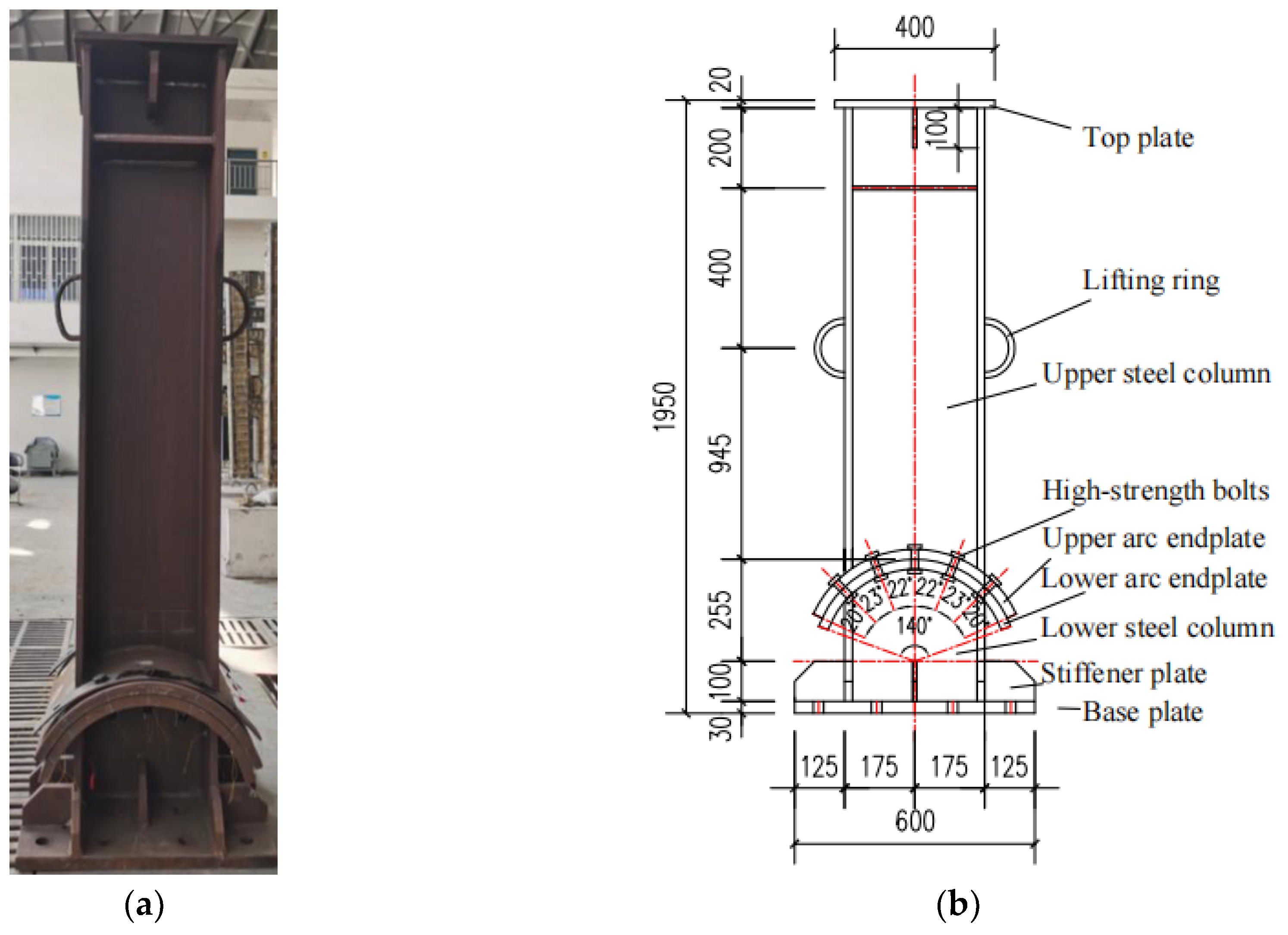
2.1. Specimen Design

The column base connection specimen with arc end-plate slip friction consists of a steel column, upper and lower arc end-plate, high-strength bolts, top plate and base plate. The section dimensions of the steel column are HW 350 mm × 350 mm × 12 mm × 19 mm (as shown in Figure 2 and Figure 3) and the total height of the specimen is 1950 mm. The width (W) of the arc end-plate is 550 mm, the thickness of the arc end-plate is 25 mm and the inner radius (R) is approximately 0.7 H (H is the height of the steel column section, i.e., 350 mm). The slip performance of the column base connection is most stable when the radius of the arc end-plate is 0.7 H [15,16]. The length of the rectangular bolt hole in the upper arc end-plate is 45 mm (Figure 4). The circular bolt holes in the lower arc end-plate have a diameter of 22 mm. The upper and lower arc end-plates are connected using S8.8M20 high-strength bolts and more design details of the connection can also be found in Figure 3. Taking into account the Chinese Code [17], a total of four full-size specimens with sliding friction steel column base connections with arc end-plates were designed to analyze the effects of the axial compression ratio, the setting of belleville springs (Bes) at the bolts, the setting of brass plates between the arc plates and different horizontal load protocols on the force performance of the specimens. The main parameters of the specimens are shown in Table 1. The specimen number H350 indicates the section dimension of the H-beam column. The first number indicates the parameter classification. The second number indicates the different loading regimes, where 1 is a variable amplitude constant loading protocol and 2 is a constant amplitude loading protocol. Two cycles of loading are carried out on each specimen. After the first test, the friction surface of the curved end-plate is cleaned and repaired, and then the second test is conducted. Take H350-1-1 to H350-4-1 as an example. Specimen H350-1-1 is the reference specimen with an axial compression ratio of 0.1 and no bass spring. H350-2-1 and H350-3-1 are set up with a bass spring and axial compression ratios of 0.2 and 0.3, respectively. H350-4-1 is based on H350-3-1 and a brass plate is set up between the curved end plates.

2.2. Material Properties and Determination of Anti-Slip Coefficient

According to the test requirements, the steel used for the sample is Q345B. The material properties of the main parts of the specimen were tested by referring to ng the Chinese Code [18]. The test mechanical properties of steel are reported in Table 2, where fy and fu are the yield strength and maximum strength, respectively. Δ is the elongation. The anti-sliding coefficient of the steel sliding surface of the specimen is measured referring the Chinese Code [19], and the steel friction coefficient is also listed in Table 3, where the friction coefficient μ is determined by the formula μ = NV/(nf·∑Pi). NV is the slip load, nf is the number of friction surfaces, μ is the friction coefficient, and ∑Pi is the sum of the measured values of the preload of the high-strength bolt when the specimen slips.

2.3. Testing Devices and Loading Regimes

The test loading device is shown in Figure 5 and the column bottom is fixed to the foundation using high-strength bolts. The axial pressure is applied through a hydraulic jack placed at the top of the column. The axial compression ratio can be calculated by the formula, n = N/(fy A), where N is the axial load, fy and A are the yield stress of the steel, and the section area of the column, respectively. A stainless-steel sliding bearing with a coefficient of friction of 0.01 is provided between the jack and the reaction beam so that the jack rotates together with the steel column during the stressing process.
The horizontal displacement load is applied through the actuator, the distance between the height of the loading center of the actuator and the center of the inner diameter of the upper curved end-plate is 1600 mm, the maximum stroke of the hydraulic actuator is ±150 mm and the load range is 500 KN. The horizontal loading protocol refers to the Chinese code for the seismic design of buildings [20], and two loading protocols of displacement control method are used. The first loading mode is a constant variable amplitude loading scheme. The specimens are loaded at 0.25Δy, 0.5Δy and 0.75Δy before sliding, cycling each stage only once. After the specimen slides, it is changed to equal displacement increment control and loaded according to 1.0Δy, 2.0Δy, 3.0Δy, …, nΔy. The loading was carried out to 6.0Δy. Each stage was cycled three times (as shown in Figure 6a). Δy is the horizontal loading displacement of the loading center of the electro-hydraulic servo actuator when the arc end-plate of the specimen slides. The second loading method is a constant equal amplitude loading protocol, where the specified displacement Δy2 is given as 5–6 times Δy and the load cycle is repeated 30 times (Figure 6b). The test loading is stopped if the load drops below 85% of the peak load or if the specimen is visibly damaged.
Before the test begins, the upper and lower arc end-plates should be aligned, and then the bolt preload should be applied to make full contact with the contact surface of the arc end plates. S8.8M20 high-strength bolts are used for this experiment, with a bolt preload of 125 kN, applied through a torque spanner, and a final construction torque of 330 N-m. Before the formal test, the specimen is preloaded and the test device and measuring equipment are checked for normal operation.

3. Description and Analysis of Experimental Phenomena

During the test, the specimen experienced two stages, i.e., the elastic stage and the rotational sliding-friction stage. The column base connection proposed in this paper is equivalent to the traditional steel column in the elastic stage. However, the upper and lower arc end-plates of column base connection are equivalent to friction dampers in the arc end-plate sliding-friction stage, in which the friction resistance was used to dissipate energy, in the arc end-plate sliding-friction stage, the specimen made different degrees of sound and vibration. After the test, it was observed that the surface of the arc end-plate had different degrees of abrasion. The specific phenomena and analysis are as follows.

3.1. Connection Rotation Slip-Friction

At the initial stage of the loading process, there is no rotation between the arc end-plates. At this time, the test specimen is in a state of elastic stress. When the loading reaches a certain degree, the rotation between the arc end-plates occurs, the static friction between the arc end-plates changes to dynamic friction, and the thrust of the hydraulic actuator decreases instantaneously. In the subsequent continuous loading process, intermittent slip rotation occurs between the arc-shaped end-plates, accompanied by varying degrees of sound and vibration. With the increase in cycle times, the degree of sound and vibration decreases, and the frequency increases. When it is loaded to 5 or 6 times the slip displacement Δy, the test is completed due to the connection rotation angle reaching 0.05 rad. The appearance of the test piece has no obvious deformation or damage.

3.2. The Abrasion of Arc End-Plate

Figure 7 shows the wear of the lower arc end-plates of specimens H350-1-1, H350-2-1 and H350-3-1 at the end of the test after the mixed constant and variable amplitude loading protocol. The arc end-plate of specimen H350-1-1 showed less wear and the wear was mainly distributed between the 1st and 2nd row of bolts from left to right, the 4th and 5th row of bolts, and near the bolt holes as well, as shown in Figure 7a. As the axial compression ratio increases, the area of the lower arc end-plate wear increases, gradually spreading from both sides of the end-plate to the middle area, the wear degree increases, and the grooves on the surface of the arc end-plate further deepen as shown in Figure 7b,c.
H350-4-1 added a thin brass plate between the arc end-plates based on the test condition of H350-3-1, as shown in Figure 8a. At the end of loading, specimen H350-4-1, the surface of the brass plate in contact with the lower arc end-plate showed uneven plough groove-like wear. The wear was mainly distributed between the 1st and 2nd row of bolts from left to right, and the 4th and 5th row of bolts, as shown in Figure 8b. The lower arc end-plate of specimen H350-4-1 shows less wear than specimen H350-3-1, with a large amount of copper powder adhering to the contact area where the wear is more severe with the brass plate, as shown in Figure 8c. This is mainly because the brass plate material is soft, and the profile material is hard. Under the action of axial compression load and bolt preload, the brass plate is in full contact with the profile and the micro-convexity on the surface of the profile will be embedded in the brass plate. During the loading process, the steel column rotates and the harder micro bumps plough through the softer brass plate, causing eventual ploughing of the brass plate. However, the sound and vibration level of specimen H350-4-1 was louder and more pronounced than that of specimen H350-3-1.
As shown in Figure 9, under the constant-amplitude horizontal loading protocol, the sliding abrasion area of the arc-shaped end-plate of the sample is expanded and the abrasion degree is increased. However, the abrasion area and degree near the bolt hole of the arc end-plate increase slightly. It can be seen from Figure 9 that after cyclic loading, a large number of abrasion iron chips are produced.
As shown in Figure 10, an enlarged view of the abrasion part of the arc end-plate. the steel plate has an obvious convex abrasion when the axial compression ratio equals 0.3 (in Figure 10c). According to the tribology principle [21]: abrasion refers to the surface damage and shedding of two solid surfaces in sliding, rolling, or impact motion. Generally, inter-metal abrasion is divided into abrasive abrasion, adhesive abrasion, surface fatigue abrasion, and corrosion abrasion. In this test, the abrasion between arc end-plates is mainly adhesive wear and abrasive wear. According to the principle of friction [22], the sliding friction between metals is a process of adhesion and sliding alternately, and the friction force is the sum of resistance caused by the Adhesion Effect and Furrow Effect. With the increase in axial pressure, the friction force between sliding interfaces increases, so the Adhesion Effect and Furrow Effect increase, which leads to the serious abrasion of arc end-plates. During the test, a thin brass plate was added between the arc end-plates. Compared with steel plate, the friction force between steel plate and brass plate under the same pressure is less than that between steel plate and steel plate, so the Adhesion Effect and Furrow Effect between steel plate and brass plate are lower than that between steel plate and steel plate. Because of the material properties, the abrasion of the brass plate is greater than that of the steel arc end-plate (shown in Figure 8b).

3.3. Loss of Preload and Deformation of Bolt

The washers used in the tests were Bes and normal high-strength bolt washers. The high-strength bolts were subjected to a construction torque applied by a torque spanner to produce a preload, with a final construction torque of approximately 330 N.m. The loss of preload after the high-strength bolt test was measured by an ultrasonic measuring device and a torque spanner. Normal high-strength bolt washers were used for specimens H350-1-1 and H350-1-2, where the load-displacement was reset to the initial position at the end of the loading test and the measured loss of construction torque was between 50% and 58.3%. Considering the severe loss of preload, Bes disc spring washers were used in subsequent tests and specimens with Bes disc spring washers showed a loss of construction torque of 0–50%, the extent of the loss of preload is shown in Table 4.
The main reason for the loss of bolt preload is the interaction of bending moment, shear force and axial force (MVP) for the high-strength bolts connected at the column base proposed in this paper [23]. The friction between the bolt and the bolt hole causes the clamping length of the bolt to become longer, resulting in a decrease in the preload force of the high-strength bolt. At the same time, the interaction of the MVP and the mutual friction between the bolt and the bolt hole leads to the deformation of the bending moment of the high-strength bolt. Another reason for the decrease in the preload force of the high-strength bolts was that the connection of the curved end-plate is an asymmetric friction connection [24]. During the continuous loading test, the upper curved end-plate drove the bolts to rotate together as they turned. The bolt hole on the screw extrusion, shear effect, and the test piece rotation will cause vibration, so that the high-strength bolts loosen, reducing their preload. After the test, the bolt was removed and the bolt was found to be bent and deformed, as shown in Figure 11. Under the same axial pressure, the sliding vibration of specimen H350-4-1 between the connected curved end plates increased by the copper plate was greater than that of specimen H350-3-1, so the preload loss of the connected bolt increased after the copper plate was assembled.

4. Test Results and Discussion

The hysteresis curve, also known as restoring force curve, is the load-displacement curve of the specimen under cyclic displacement loading. It is the basis for the analysis of specimen stiffness degradation, energy consumption, and seismic performance.

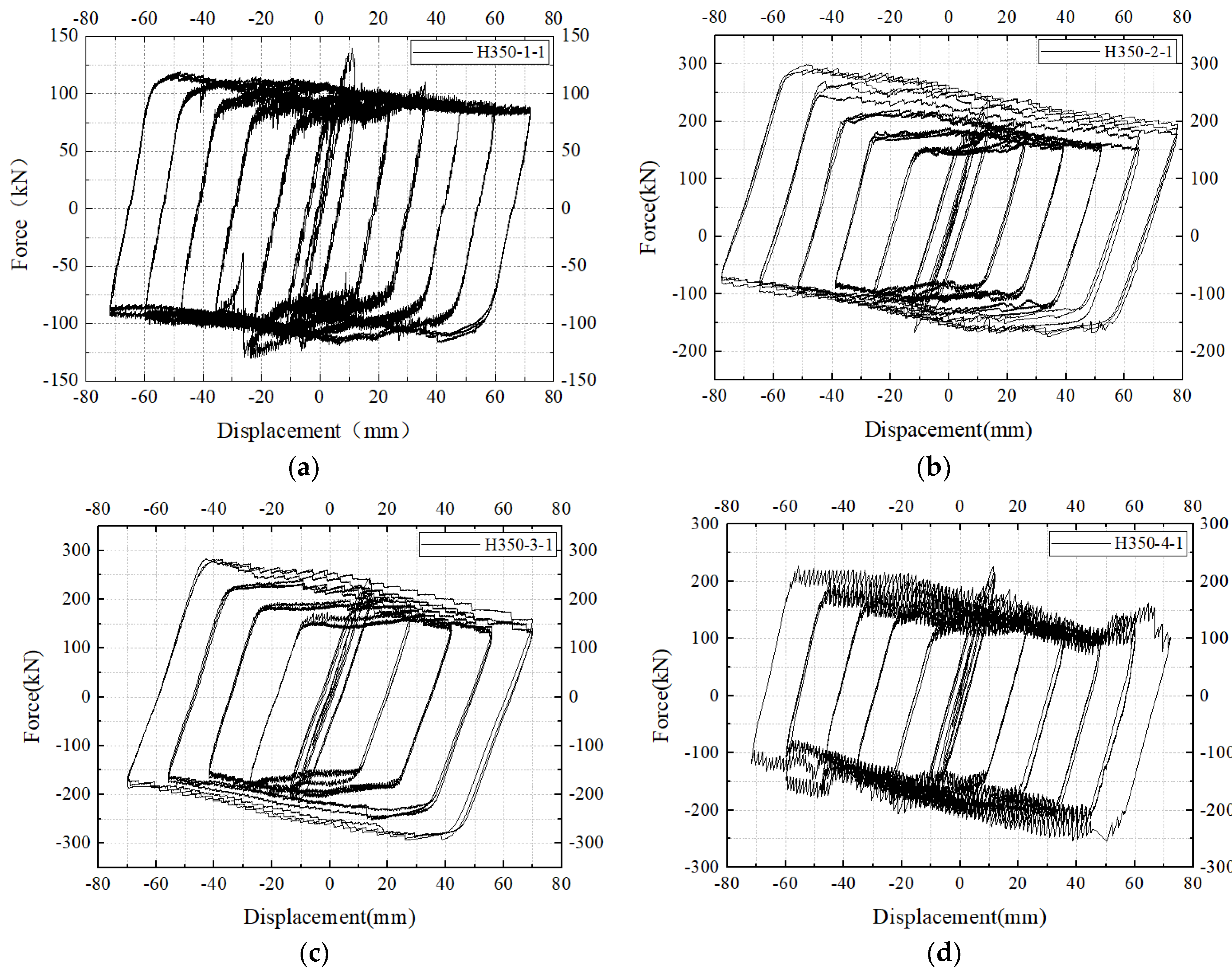
4.1. Hysteretic Curve
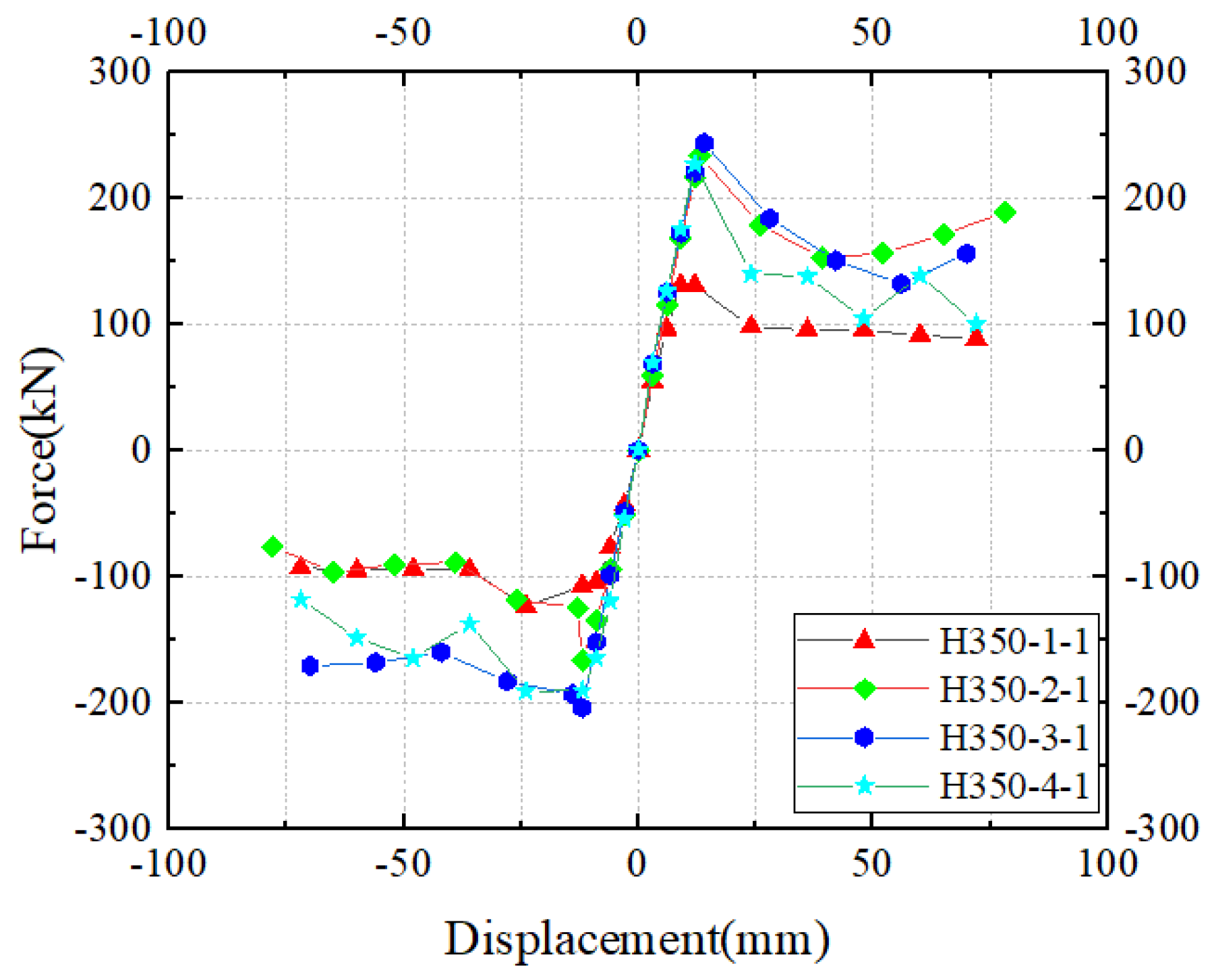
The Hysteresis curves from the variable amplitude constant-amplitude horizontal loading test were shown in Figure 12. The arc end-plates did not slide relative to each other during the initial loading period. The specimens were in the elastic state before the arc end-plate began to slip. Thus the load-displacement curves were approximated in a straight line. After the arc end-plate of the specimen slides, the slip section appears in the hysteretic curve, with the loading test, the load-displacement hysteretic curve is similar to the parallelogram. From Figure 12, the sliding load of the arc end-plate of the specimen increases with the axial pressure ratio. At the same time, after the circular end-plate slides, the curve slope in the slip stage of the hysteretic curve also increases. After the application of the brass plate, the buffeting amplitude of the specimen in the slip stage of the hysteretic curve increases significantly, the load-carrying capacity decreases, and the curve slope of the slip stage of the hysteretic curve decreases.
The horizontal load of each specimen showed different degrees of jitter, which was due to the influence of the adhesion mechanism and wear mechanism of friction when the objects in contact with each other and squeezed each other showed relative sliding, resulting in an unstable friction coefficient during the sliding process and thus an unstable jitter in the bearing capacity [22]. Compared with specimens H350-2-1 and H350-3-1, the hysteresis curve of specimen H350-1-1 was more dramatic in its jittering phenomenon, and the load showed a huge change when the horizontal displacement was loaded to −30 mm. The main reason for this is that there is a large amount of rust on the frictional contact surface of the specimen, and the sliding mechanism and friction mechanism are more complicated during the stressing process of the specimen. The high horizontal load on the specimen at the beginning of loading is mainly due to the fact that the horizontal load is mainly provided by the axial load and the static friction between the members. After the sliding of the arc end-plates, the static friction between the members turns into dynamic friction and the load-carrying capacity decreases rapidly. As the test progresses, the horizontal load-carrying capacity of the specimen increases. The main reason for this is that the specimen drives the bolts to slide together during the sliding process and a certain degree of tensile action occurs between the specimen and the bolts. On the other hand, errors in the assembly of the specimen prior to the test caused the upper and lower arc plates to not be perfectly aligned. Moreover, due to the complex mechanism of friction, the test piece was not completely reset during the sliding process, and there was an in-plane or out-of-plane deflection, resulting in an increase in the load-bearing capacity of the test piece during the stressing process.
The hysteresis curves from the constant-amplitude horizontal loading test were shown in Figure 13. With the progress of cyclic loading, the horizontal force of the hydraulic actuator continues to decrease. When the test load is cycled to 10 times Δy2, the horizontal force decreases more and more slowly. When the load is cycled to 20 times Δy2, the decrease in the horizontal force is negligible. The load-carrying capacity of the specimen also decreases more and more slowly. It can also be seen from the figure that the decline rate of the load-carrying capacity of the specimen slows down after using Bes. The reason is the pressure and the Bes reduce the decrease in the pre-tension force of high-strength bolts due to the cyclic loading of large displacement. As the number of cyclic tests increase, the pre-tension force of high-strength bolts continues to decrease. When the test load is cycled to 10 times Δy2, the reduction range of the pre-tension force of high-strength bolts decreases, and the supply of pressure between arc end-plates by high-strength bolts continues to decrease. When the load is cycled to 20 times Δy2, the decrease in the pre-tension force of high-strength bolts is also negligible. At this time, although the pressure between arc end-plates is provided by axial pressure and the pre-tension force of high-strength bolts, the effect of axial pressure is greater than that of the pre-tension force of high-strength bolts. After adding brass between the arc end-plates, although the load-carrying capacity of the specimen with brass plate is reduced, the decreased rate of the load-carrying capacity of the sample is lower than that of the sample without brass.

4.2. Skeleton Curve

Specimens H350-1-1, H350-2-1, H350-3-1, H350-4-1 were selected for analysis. The force-displacement skeleton curves were shown in Figure 14, and the characteristic values of the skeleton curves were reported in Table 5.
From Figure 14 and Table 5, the skeleton curves of each specimen at the elastic stage coincide. The slip threshold and slip displacement of the specimen increase with the increase in axial pressure ratio, and the slope of the curve increases in the slip stage. After using the brass plate, the slip threshold and slip displacement of the specimen is reduced.

4.3. Stiffness Degradation

Specimens H350-1-1, H350-2-1, H350-3-1, and H350-4-1 were selected for analysis. Figure 15 shows the stiffness degradation curves of the specimens. The secant stiffness K is used to represent the stiffness degradation of the connection. At the initial stage of loading, the arc end-plate of the specimen did not slip, and the stiffness degradation of the connection was insignificant. After the arc end-plate of the connection slipped, the stiffness decreased significantly. Meanwhile, the stiffness degradation slows down gradually when the loading displacement increases. It can also be seen from the figure that the initial stiffness increased along with the increase of the axial compression ratio and the brass plate has no obvious effect on the initial stiffness of the connection when the axial pressure is the same.

4.4. Energy Dissipation Behavior

To study the effect of vertical load and other variables on the energy dissipation ability of the connections, the equivalent viscous damping ratio and energy dissipation coefficient were calculated for the column base connections with slip-friction. The energy dissipation coefficient Ed [21,22] is calculated by the following formula,
h e = 1 2 π E d
Specimens H350-1-1, H350-2-1, H350-3-1, and H350-4-1 were selected for analysis. The calculated he and Ed are listed in Table 6. The energy dissipation performance of the connections can be improved due to the application of the brass plates. Loss of the bolt preload can also be reduced by using the Bes, while energy dissipation performance is insignificantly effective. However, the energy dissipation performance of the connection is improved significantly when the vertical pressure increases. From the table, the connections have good energy consumption performance.

5. Conclusions

The seismic performance of steel column base connections with arc end-plates slip-friction was studied by conducting the test. The main conclusions are as follows:
(1) The steel column base connection with sliding arc end-plates has a good load-carrying capacity and hysteresis performance. The specimen dissipates seismic energy through the frictional behavior of the upper and lower arc end-plates, achieving a non-destructive performance of the column base connection, and the specimen can be used continuously after bolt replacement.
(2) Axial pressure is beneficial to the connection proposed in this paper. which can improve the load-carrying capacity, energy consumption performance, sliding threshold, and initial stiffness and reduce the loss of the pre-tension force of high-strength bolts.
(3) With the application of brass plate, although the load-carrying capacity of the connection decreases, the energy dissipation performance, Adhesion Effect and Furrow Effect of the steel column-based connection with arc end-plates the sliding-friction has been effectively improved, while the initial stiffness of the connection has no obvious influence.
(4) The use of Bes in connection can reduce the loss of pre-tension force of high-strength bolts, but it cannot avoid the deformation of high-strength bolts and has no significant impact on the seismic performance of the connection.

Author Contributions

Conceptualization, C.L. (Chengyu Li) and A.Z.; Methodology, C.L. (Chengyu Li) and A.Z.; Software C.L. (Cong Luo); Validation, C.L. (Chengyu Li) and C.L. (Cong Luo); Formal analysis, C.L. (Cong Luo); Investigation, C.L. (Chengyu Li). and A.Z.; Resources, C.L. (Chengyu Li); Data curation, C.L. (Chengyu Li) and C.L. (Cong Luo); Writing-original draft, C.L. (Cong Luo); Writing-review and editing, C.L. (Chengyu Li); Visualization, C.L. (Cong Luo); Supervision, C.L. (Chengyu Li) and A.Z.; Project administration, C.L. (Chengyu Li); Funding acquisition, C.L. (Chengyu Li). All authors have read and agreed to the published version of the manuscript.

Funding

This work was financially supported by the National Natural Science Foundation of China (Granted number: 51878522).

Institutional Review Board Statement

Not applicable.

Informed Consent Statement

Not applicable.

Data Availability Statement

The data presented in this study are available on request from the corresponding author.

Conflicts of Interest

The authors declare no conflict of interest.

References

  1. Miller, D.K. Lessons Learned from the Northridge Earthquake. Eng. Struct. 1998, 20, 249–260. [Google Scholar] [CrossRef]
  2. Mahin, S.A. Lessons from Damage to Steel Buildings during the Northridge Earthquake. Eng. Struct. 1998, 20, 261–270. [Google Scholar] [CrossRef]
  3. Suzuki, Y.; Lignos, D. Collapse Behavior of Steel Columns as Part of Steel Frame Buildings: Experiments and Numerical Models. In Proceedings of the 16th World Conference on Earthquake Engineering (16WCEE), Santiago, Chile, 9–13 January 2017. [Google Scholar]
  4. Yang, T.S.; Popov, E.P. Experimental and Analytical Studies of Steel Connections and Energy Dissipators. Ph.D. Thesis, University of California, Berkeley, CA, USA, 1995. [Google Scholar]
  5. Hsen-Han, K.; Clifton, C.; Butterworth, J.; MacRae, G.; Gledhill, S.; Sidwell, G. Development of the Self-Centering Sliding Hinge Joint with Friction Ring Springs. J. Constr. Steel Res. 2012, 78, 201–211. [Google Scholar]
  6. Cavallaro, G.F.; Francavilla, A.B.; Latour, M.; Piluso, V.; Rizzano, G. Cyclic Response of Low Yielding Connections Using Different Friction Materials. Soil Dyn. Earthq. Eng. 2018, 114, 404–423. [Google Scholar] [CrossRef]
  7. Iyama, J.; Seo, C.Y.; Ricles, J.M.; Sause, R. Self-Centering MRFs with Bottom Flange Friction Devices under Earthquake Loading. J. Constr. Steel Res. 2009, 65, 314–325. [Google Scholar] [CrossRef]
  8. Borzouie, J.; MacRae, G.A.; Chase, J.G.; Rodgers, G.W.; Clifton, G.C. Experimental studies on cyclic performance of column base weak axis aligned asymmetric friction connection. J. Constr. Steel Res. 2015, 112, 252–262. [Google Scholar] [CrossRef]
  9. Borzouie, J.; MacRae, G.A.; Chase, J.G.; Rodgers, G.W.; Clifton, G.C. Experimental studies on cyclic performance of column base strong axis–aligned asymmetric friction connections. J. Struct. Eng. 2016, 142, 04015078. [Google Scholar] [CrossRef]
  10. Liu, X.; Chicchi, R.; Shahrooz, B. An Innovative Resilient Rocking Column with Replaceable Steel Slit Dampers: Experimental Program on Seismic Performance. Eng. Struct. 2019, 183, 830–840. [Google Scholar] [CrossRef]
  11. Freddi, F.; Dimopoulos, C.A.; Karavasilis, T.L. Rocking damage-free steel column base with friction devices: Design procedure and numerical evaluation. Earthq. Eng. Struct. Dyn. 2017, 46, 2281–2300. [Google Scholar] [CrossRef] [Green Version]
  12. Freddi, F.; Dimopoulos, C.A.; Karavasilis, T.L. Experimental evaluation of a rocking damage-free steel column base with friction devices. J. Struct. Eng. 2020, 146, 04020217. [Google Scholar] [CrossRef]
  13. Latour, M.; Rizzano, G.; Santiago, A.; da Silva, L.S. Experimental response of a low-yielding, self-centering, rocking column base joint with friction dampers. Soil Dyn. Earthq. Eng. 2019, 116, 580–592. [Google Scholar] [CrossRef]
  14. Elettore, E.; Freddi, F.; Latour, M.; Rizzano, G. Design and analysis of a seismic resilient steel moment resisting frame equipped with damage-free self-centering column bases. J. Constr. Steel Res. 2021, 179, 106543. [Google Scholar] [CrossRef]
  15. Li, C.; Liu, Q.; Li, G. Seismic behavior of steel column base with slip-friction connections. Materials 2020, 13, 3986. [Google Scholar] [CrossRef] [PubMed]
  16. Li, C.; Lai, Z. Study on Mechanical Performance of Column Base Joint with Slip-Friction Arc Endplates. In Proceedings of the International Conference on Green Building, Civil Engineering and Smart City; Springer: Singapore, 2023; pp. 1030–1038. [Google Scholar]
  17. GB 50017–2016; Code for Design of Steel Structures. Ministry of Housing and Urban-Rural Development of China, Architecture & Building Press: Beijing, China, 2015.
  18. GB/T 228-2010; Metallic Materials Tensile Test Method at Room Temperature. National Standards of the People’s Republic of China, Architecture & Building Press: Beijing, China, 2002.
  19. GB 50011–2010; Code for Seismic Design of Buildings. National Standards of the People’s Republic of China, Architecture & Building Press: Beijing, China, 2010.
  20. JGJ/T 101–2015; Specification of Testing Method for Earthquake Resistant Building. Ministry of Housing and Urban-Rural Development of China, Architecture & Building Press: Beijing, China, 2015.
  21. Wen, S.Z.; Huang, P.; Tian, Y.; Ma, L.R. Principles of Tribology, 5th ed.; Tsinghua University Press: Beijing, China, 2018. [Google Scholar]
  22. Chouery, K.E.; Kui, F.A.N.; Liang-jiu, J.I.A. State-of-the-art review of symmetric and asymmetric friction connections: Seismic behavior and design methods. Eng. Mech. 2021, 38, 22–37. [Google Scholar] [CrossRef]
  23. Ramhormozian, S.; Clifton, G.C.; MacRae, G.A.; Davet, G.P.; Khoo, H.-H. Experimental Studies on Belleville Springs Use in the Sliding Hinge Joint Connection. J. Constr. Steel Res. 2019, 159, 81–94. [Google Scholar] [CrossRef]
  24. Golondrino, J.C.C.; MacRae, G.A.; Chase, J.G.; Rodgers, G.W.; Clifton, G.C. Asymmetric Friction Connection (AFC) design for seismic energy dissipation. J. Constr. Steel Res. 2019, 157, 70–81. [Google Scholar] [CrossRef]
Figure 1. Schematic diagram of column base connection.
Buildings 12 02012 g001
Figure 2. Sectional sizes of H-shaped section (unit: mm).
Buildings 12 02012 g002
Figure 3. Design details of the specimen (unit: mm): (a) Specimen; (b) Dimensional drawings.
Buildings 12 02012 g003
Figure 4. Dimensions of the upper arc end-plate: (a) the arc end-plate; (b) the oblong bolt holes (unit: mm).
Buildings 12 02012 g004
Figure 5. Test set-up.
Buildings 12 02012 g005
Figure 6. Horizontal loading protocol: (a) Variable amplitude constant-amplitude loading protocol; (b) Constant-amplitude loading protocol.
Buildings 12 02012 g006
Figure 7. Influence of axial compression ratio on wear of lower arc end-plates: (a) H350-1-1; (b) H350-1-2; (c) H350-1-3.
Buildings 12 02012 g007
Figure 8. Specimen H350-4-1: (a) H350-4-1; (b) Brass abrasion; (c) Abrasion of lower arc end-plate.
Buildings 12 02012 g008
Figure 9. Wear on the friction surface of the lower arc end-plate of each specimen under an equal amplitude loading protocol: (a) H350-1-2; (b) H350-2-2; (c) H350-3-2;(d) H350-4-2.
Buildings 12 02012 g009
Figure 10. Local wear on the friction surface of the lower arc end-plate of each specimen under an equal amplitude loading protocol: (a) H350-1-1; (b) H350-2-1; (c) H350-3-1; (d) H350-4-1.
Buildings 12 02012 g010
Figure 11. High-stre bolt of specimen: (a) H350-3-2 (b) H350-4-2; (c) Bending deformation of No.1, 9 and No.10 ngth bolts of H350-3-2; (d) Bending deformation of No. 5, No. 7 and No. 8 bolts of H350-4-2.
Buildings 12 02012 g011
Figure 12. Force−displacement curves: (a)H350-1-1; (b)H350-2-1; (c) H350-3-1; (d)H350-4-1.
Buildings 12 02012 g012
Figure 13. Force-displacement curves: (a) H350-1-2; (b) H350-2-2; (c)H350-3-2; (d) H350-4-2.
Buildings 12 02012 g013
Figure 14. Force-displacement skeleton curves.
Buildings 12 02012 g014
Figure 15. Stiffness degradation curves.
Buildings 12 02012 g015
Table 1. Parameters of the specimens.
SpecimenSteel Column Section Size/mmAxial Compression Ratio nWasher TypeWhether to Use Brass PlateNumber of High-Strength BoltsHorizontal Loading System
H350-1-1350 × 350 × 12 × 190.1OrdinaryNo10variable amplitude constant-amplitude loading
H350-2-1350 × 350 × 12 × 190.2BesNo10
H350-3-1350 × 350 × 12 × 190.3BesNo10
H350-4-1350 × 350 × 12 × 190.3BesYes10
H350-1-2350 × 350 × 12 × 190.1OrdinaryNo10constant-amplitude loading
H350-2-2350 × 350 × 12 × 190.2BesNo10
H350-3-2350 × 350 × 12 × 190.3BesNo10
H350-4-2350 × 350 × 12 × 190.3BesYes10
Table 2. Material properties.
TypeThickness (Actual Thickness)/mmfy/MPafu/MPaElongation
δ/%
Web12(11.9)37653229.5
Flange19(18.8)43653730.7
Arc end-plate25(25.1)36951223.2
Table 3. Friction coefficient of steel sliding surface.
Type∑Pi/kNSliding Load NV/kNFriction Coefficient μ
Single bolt specimen12552.40.42
Four bolts specimen500205.60.41
Table 4. Pre-tightening force loss of connecting high-strength bolts.
Specimen I.D.The Pre-Tightening Force of Bolts after Loading/N m
No.1 BoltNo.2 BoltNo.3 BoltNo.4 BoltNo.5 Bolt
H350-1-1125~150125~150125~150125~150125~150
H350-1-2125~150125~150125~150125~150125~150
H350-2-1225~250225~250225~250225~250225~250
H350-2-2150~175175~200175~200175~200150~175
H350-3-1250~275275~300275~300275~300250~275
H350-3-2175~200175~200200~225175~200175~200
H350-4-1175~200250~275250~275175~200175~200
H350-4-2150~175175~200225~250175~200150~175
Table 5. Force and displacement at characteristic points of the skeleton curves.
Specimen I.D.Slip Threshold Fy/kNSliding Displacement Δm/mm
H350-1-1139.911.9
H350-2-1233.412.8
H350-3-1242.813.6
H350-4-1225.111.8
Table 6. The equivalent viscous damping ratios and energy dissipation coefficients.
Specimen I.D.Equivalent Viscous Damping
Ratio/he
Energy Dissipation
Coefficient/Ed
H350-1-10.674.18
H350-2-10.815.08
H350-3-10.825.18
H350-4-10.865.39
Publisher’s Note: MDPI stays neutral with regard to jurisdictional claims in published maps and institutional affiliations.

