Article

Life-Cycle Assessment of Contemporary and Classical Seismic Retrofitting Approaches Applied to a Reinforced Concrete Building in Israel

Department of Civil Engineering, Ariel University, Ariel 40700, Israel
*
Author to whom correspondence should be addressed.
Buildings 2022, 12(11), 1854; https://doi.org/10.3390/buildings12111854
Submission received: 19 September 2022 / Revised: 25 October 2022 / Accepted: 28 October 2022 / Published: 2 November 2022
(This article belongs to the Collection Sustainable Buildings in the Built Environment)

Abstract

:
This study aims to select an eco-friendly earthquake-resistant design using life-cycle assessments (LCAs). The study compares LCAs of three retrofitting cases: concrete shear-wall strengthening (Case 1); reinforced concrete column jacketing with shear-wall strengthening (Case 2); and high-damping rubber bearing base isolation with viscous fluid damping devices (Case 3). These cases were applied to a five-story reinforced concrete building built according to the design principles widely used in Israel in the 1970s. The seismic-bearing capacity of the retrofitted building was improved in all three cases, where Case 3 was observed as being the most effective retrofitting measure. The environmental performance of the retrofitting measures was assessed using the ReCiPe 2016 midpoint, which indicated that Case 3 was the best with the least environmental impact, Case 1 was intermediate with moderate environmental impact, and Case 2 was the worst with the most environmental impact. However, the ReCiPe 2016 endpoint single-score results showed that Case 3 caused significantly less damage than Cases 1 and 2, which caused similar significant environmental damage. These results indicate that LCA should be used to select an eco-friendly earthquake-resistant design.

1. Introduction

Seismic retrofitting of old buildings is a pressing problem in many countries. The conventional retrofitting method involves adding reinforced concrete (RC) stiffening elements to the structure (concrete shear-wall strengthening) [1]. In Israel, for example, this approach is widely used as part of a nationwide statutory plan for improving the seismic capacity of buildings built during the 1970s, also known as Tama 38 [2].
Another well-known RC strengthening strategy is column jacketing. By laminating existing columns with a layer of RC, composite columns are obtained, providing a lateral load-carrying system with better load capacity [3]. After the 1985 El Centro earthquake, this was the preferred alternative for retrofitting of many medium-rise structures affected by this seismic event [4]. As with every other method, this approach has some pros and cons, e.g., while it is beneficial in providing a uniform increase in strength and stiffness [5], it involves severe disruption to the building’s inhabitants during the construction [3].
Over the last few decades, new strategies have been suggested for the seismic retrofitting of structures. One of these methods is based on energy dissipation by viscous fluid dampers, which are known to be effective for seismic structural applications [6,7,8].
An additional retrofitting method is to use base isolation. The main idea is to isolate the structure from ground motion by adding special devices, such as high-damping rubber bearings [1,9,10] between the foundations and the structure [11,12].
However, one of the issues with base isolation systems is their performance under near-fault ground motions. Such motions can cause exhaustion of the isolator’s translation range [13] and other severe problems. It was found that adding dampers to an isolation system effectively reduces the displacement in the isolators and the likelihood of these issues [14,15]. Numerous works that support this fact can be found in the literature [16,17,18]. Additionally, recent works point to base isolation [19] and energy-dissipation [20,21] devices as effective retrofitting techniques for improving the seismic response of existing structures [22]. It was shown that they can prevent the economic and social consequences related to various problems (e.g., collapse of nonstructural elements [19], fire [20], energetic and functional points of view [21]).
However, these retrofitting methods consume substantial amounts of concrete and steel, which might entail significant environmental damage. According to Stengel and Schiessl [23], cement and steel are the leading building materials in terms of carbon dioxide emissions from their manufacturing processes. Their high carbon dioxide emissions are the result of the high energy consumption required for the production of Portland cement and steel [23,24]. In Portland cement production, the calcination of limestone leads to additional CO2 emissions [24].
Therefore, the main sustainability goal of the construction industry is to decrease the quantities of cement and steel as much as possible. This can be approached using a life-cycle assessment (LCA) methodology that can search for more environmentally friendly alternatives for retrofitting problems.
Currently, LCA of building-related retrofitting methods is a growing topic of research in the construction industry. Wei et al. [25] conducted LCA of carbon dioxide emissions caused by a concrete retrofitting jacketing method. Along with environmental impacts, they also evaluated the social and economic aspects associated with the different repair techniques.
Vitiello et al. [26] conducted LCAs of four retrofitting methods applied to a building in Italy: fiber-reinforced polymer (FRP)-based strengthening sheets, FRP-RC jacketing, insertion of RC shear-wall-based strengthening, and insertion of rubber bearings and friction isolators. The friction isolators and rubber bearings were the best solution, with the least environmental damage, whereas the RC shear-wall-based strengthening method was the worst solution, with maximal environmental damage. Salgado et al. [27] studied three seismic retrofitting alternatives for an RC building in the US: RC column jacketing, the addition of RC shear walls, and beam weakening. In these studies, Vitiello et al. [26] and Salgado et al. [27] concluded that shear-wall strengthening was the worst solution, with the maximum environmental damage.
Ribakov et al. [6] continued to conduct LCAs of conventional concrete wall strengthening (CWS) and modern retrofitting methods. The latter accounted for viscous dampers installed via steel chevron braces (VD&SB) and viscous dampers installed via concrete chevron braces (VD&CB). Two additional retrofitting approaches were analyzed by Ribakov et al. [1]: The base isolation using high-damping rubber bearings (HDRBs), and base isolation using seismic isolation columns (SICs). These utilization of these modern methods [1,6] was evaluated for a building in Israel and, compared to the conventional ones, they demonstrated lower environmental damage.
Despite these well-grounded studies, their findings depend on country-specific building designs and the possibility of earthquakes [28]. Therefore, there is a need to study such configurations under local conditions and, thus, to extend the basis of knowledge of how they will perform in local settings with different buildings and the retrofitting approaches applied to them.
Thus, this study continues previous LCA studies of the newer retrofitting methods in Israel (i.e., VD&SB and VD&CB [6], and HDRBs and SICs [1]) by introducing two additional methods: RC column jacketing with shear-wall strengthening, and high-damping rubber bearing base isolation combined with viscous fluid damping devices (HDRB&VD). These structural retrofitting solutions are different from the previously studied retrofitting approaches. Therefore, this study aims to address this research gap by analyzing these two additional methods.
Combining RC columns’ jacketing with shear-wall strengthening is a retrofitting method that has not previously been environmentally evaluated. It uses shear-wall strengthening on the occupied floors in conjunction with jacketing of columns on the ground floor. This enables balanced distribution of additional stiffness on the ground floor, does not involve blocking of openings, and reduces the disturbance to the structure’s occupants. It also intrinsically differs from the previously studied measures that involve energy-dissipation devices or base isolation.
In summary, RC column jacketing, shear-wall strengthening, and hybrid solutions of the HDRB&VD type are known to effectively improve the performance of old buildings in seismic-related scenarios. However, their application to buildings built in Israel during the 1970s has not yet been environmentally evaluated. Furthermore, the analysis here accounts for the structure’s foundation performance, the retrofitting that these foundations require in each alternative, and its significance to the LCA. The purpose of this study is to evaluate three alternatives for earthquake-resistant structures using LCA and to select an environmentally friendly alternative.
Notably, this study presents a conceptual comparison, rather than a detailed one, for pointing out the general implications of each of the methods. Such an observation furnishes a general sense of the environmental impacts of the discussed methods, which is important when considering them for retrofitting. This is why many structural details that are usually mentioned in various case studies are absent here. For the sake of maintaining the strategic level of the discussion, the focus is placed on structural aspects with a major contribution to the studied aspects, while ignoring those with a minor contribution.

2. Materials and Methods

2.1. Research Framework

This study considers three retrofitting alternatives applied to a typical Israeli residential five-story RC building (see [6]): (i) concrete shear-wall strengthening (CWS) (Case 1; Figure 1), (ii) reinforced concrete column jacketing with shear-wall strengthening (Case 2; Figure 2), and (iii) high-damping rubber bearing base isolation with viscous fluid damping devices (Case 3; Figure 3). These cases are explained below. A non-retrofitted version of the original structure serves here as a control case. The structural attributes of this building resemble those of many old buildings built in Israel during the 1970s. Its first floor is open and consists of C20-concrete columns, with a 30 × 30 cm square section. The height of each floor is 2.6 m and the spans are 6 m in both directions. The floor slabs are 30 cm thick and are subjected to dead and live loads of 4.27 kN/m2 and 0.49 kN/m2, respectively. This building and others like it were designed and built before the Israeli standard for earthquake resistance became valid [2]. Consequently, most of them do not comply with the contemporary seismic provisions, are susceptible to earthquakes, and require suitable retrofitting.
Modeling the building’s dynamics requires the presupposition of several engineering premises. Here, it was assumed that the ceilings are rigid and that the building’s mass is lumped at the ceilings. Additionally, it was assumed that the column–floor links are rigid, that the axial stiffness of the columns is much greater than their flexural stiffness, that the floors remain horizontal during the vibration, and that the floors’ centers of mass coincide with their centers of rigidity. Based on the above, each floor has three decoupled DOFs—two lateral and one rotational. Thus, a shear building model with one horizontal DOF on each floor was used for describing the dynamic properties of the structure in its plane of symmetry [29]. Both Case 1 and Case 2 included retrofitting of the shear walls. Figure 1 presents the two types of shear-wall distribution that were used in these cases. They are referred to as type I and type II distributions. Table 1 associates each case and floor with the implemented distribution. In Case 1, the ground floor and the 1st floor were retrofitted by type I distribution and the other floors by type II distribution. All of the walls were set to have the same thickness (15 cm) and percentage of reinforcement (1%). This design was conducted concurrently with the numerical time–history simulations described below in Section 2.2. The walls were designed to reduce the seismic demand on the original structural elements and keep them elastic during the vibration. Additionally, the shear walls’ distribution accounted for three issues related to common retrofitting practice.
The first issue is that many structures in need of retrofitting are already occupied. Consequently, they have limited access to many structural elements and fewer retrofitting options. For this, in many retrofitting solutions, bracings are mainly implemented at the structure’s perimeter and, if necessary, in the internal staircase as well. This issue, however, leads to the second one: Usually, the perimeter of the ground floor is used for parking spots for the residents’ cars. This is because the columns in the inner zones of the ground floor hinder cars from conveniently maneuvering into and out of the parking spots. Additionally, internal zones usually serve for gardening and/or various facilities. In summary, the problem is that on the one hand, the ground floor’s perimeter is the most attractive area for retrofitting, as it is accessible for construction operations and it allows the efficient continuation of the upper diaphragms down to the ground. On the other hand, this kind of retrofitting blocks existing parking spots, conflicting with the residents’ right for car parking. A third issue that is considered here, and was not accounted for in previous publications [1,6], concerns the impact of retrofitting on the structure’s foundation system. During the vibration, the high rigidity of the shear walls creates intensive concentrated reactions at the foundations, thereby necessitating their extensive retrofitting. In the wake of these problems, RC shear walls were embedded in Case 1 only at the circumferential walls, and no retrofitting elements were placed in the internal staircase. As for the second and third issues, by allowing the shear walls to span two bays in the ground floor, the reactions in the foundations were maintained within reasonable limits, keeping the foundations’ retrofitting practical and leaving the other bays free for parking. This, however, was at the expense of those parking spots blocked by the added shear walls. Figure 4 illustrates the change in parking spots between the control case and Case 1. Extensive retrofitting of the foundation system was required for bearing the vertical force demand. More than half of the square foundations of the structure were enhanced to the required capacity. The majority of the work was done in the perimeter of the building, where high vertical loads are exerted by the shear walls. This includes pulling forces, leading to drilling and casting of piles at several locations.
Case 2 combined two retrofitting approaches (Figure 3). On the one hand, the ground floor allowed relatively easy access to structural elements, thereby allowing the use of column strengthening. On the other hand, the building was assumed to be occupied during the retrofitting, making construction activities inside the apartments impossible. Consequently, many retrofitted columns from the ground floor could not be continued into the floors above. Considering this, in Case 2, an integrated solution was utilized. Similarly to Case 1, the design was carried out through time–history simulations. Floors 2–5 were modified using the CWS concept, while the ground floor’s columns were strengthened only by RC jacketing and without any shear walls. A type I shear-wall distribution was used on floors one and two, while type II distribution was used on floors three and four. The walls’ thickness was set to 15 cm and the reinforcement percentage was set to 1.2%. Such a retrofitting retains the advantages of an open ground floor while reducing the disruption to the building’s residents, i.e., the disruption that would have been evoked if RC jacketing had been applied to the rest of the floors. All of the columns on the ground floor were jacketed with an 8 cm thick RC coating, using C30 concrete. The jacketing percentage of the reinforcement was 1.2%. Suitable anchorings for the jacketing’s reinforcing bars were created in the foundations and ceiling. The presence of shear walls on the higher floors created large reactions at the relevant columns; as a result, similarly to Case 1, extensive retrofitting had to be performed at the foundations to allow them to provide the necessary reactions. Compared to the control case, the arrangement of the parking spots remained unchanged.
Figure 4 presents the configuration of Case 3—HDRB base isolation with viscous fluid damping devices. While the installation of dampers in an existing building is quite straightforward, placing the isolators is a somewhat more challenging. These are placed in columns that are already functioning as load-carrying elements and cannot be simply removed and reconstructed. A possible practice in such cases is to retrofit the columns one by one, where hydraulic jacks and temporary supports are used for unloading the column. After the load is transferred from the column to the temporary supports, the column can be incised in order to place the isolator. Next, the load is gradually transferred back to the new column, and the process is repeated on the next column [30]. The high-damping rubber bearings’ properties were set in accordance with those of commercial ones. Each isolator had an effective area of 3317 mm2, rubber thickness of 198 mm, and vertical service load capacity of 1800 kN. Their equivalent stiffness was 656.7 kN/m and their equivalent damping ratio was 22%. The dead load exerted to the isolator limited the shear strain in the rubber to 260%. Two pairs of viscous fluid damping devices were installed on the ground floor. They were coupled with the structure using chevron braces made of C30 concrete. The dampers’ equivalent linear viscous damping was 4000 kNm/s, their allowable stroke was ±12 cm, and their maximum load capacity was 2000 kN. Figure 2 shows the dampers’ distribution on the ground floor. As in Case 1, a time–history design was utilized through simulations of the retrofitted structure to a set of accelerograms. The parameters were set for obtaining a satisfactory seismic performance of the structural elements. Additionally, modifications to the foundations’ system were required to cope with the enlarged vertical reactions during the structural vibration. Another issue was that even though the seismic loading was substantially reduced, the bending stresses in the ground-floor columns were still too close to their capacity. One should bear in mind that these columns have a rather small cross-section and are assumed to be made of low-strength concrete. To solve this problem, column jacketing was applied to this case as well. Here the jacketing’s thickness was 4 cm and the percentage of reinforcement was 1.2%. However, it should be emphasized that unlike Case 2, the jacketing was taken merely as a complementary step and did not play a major role in the seismic retrofitting. The original non-retrofitted building served as a control case.
In all of the retrofitting cases, extensive construction operations were executed on the ground floor, leading to the complete replacement of the asphalt in the parking spaces. However, the scale of asphalt replacement was identical for all of these cases, making it a non-relevant factor for comparison of the alternatives. Hence, the environmental damage associated with the asphalt was not taken into consideration.
Dynamic models of shear buildings were used for Cases 1–3 as well. The masses were lumped at the ceilings and, in Cases 1 and 2, also included the mass added by the retrofitting. Proportional damping was assumed, with damping ratios typical of concrete structures. The lateral stiffness included the rigidity of the original columns, shear walls, and jacketing. In Case 3, the isolators were modelled as linear springs and dashpots connected in series with the ground-floor columns.
Each of the retrofits caused a substantial variation in the structure’s dynamic properties. These are mainly reflected in the modal natural periods and damping ratios shown in Figure 5. The Case 1 and 2 retrofits, which were based on extensively increasing the structural rigidity, led to substantial shortening of the natural periods. Conversely, Case 3 caused an increase in the first two natural periods, but almost no change in the others. This was an anticipated result, considering that this retrofit was based on creating a flexible interface between the ground and the structure. As for damping ratios, the control case, Case 1, and Case 2 had similar damping ratios, whereas Case 3 benefited from increased damping due to the supplementary damping provided by the HDRB isolators and the VDs. The effective modal masses are given in Table 2.

2.2. Seismic Response Analysis

This study places a focus on the environmental performance of Cases 1, 2, and 3. However, first, the seismic effectiveness of each of the alternatives was verified to provide a basis for the correct functional unit in LCA evaluation.
The seismic response was examined by originally developed subroutines written in MATLAB. Then, the LCAs of Cases 1, 2, and 3 were evaluated using ReCiPe 2016 midpoint and endpoint single-score results. Finally, the LCAs of the ReCiPe 2016 endpoint single-score results of Cases 1, 2, and 3 were compared using a two-stage nested mixed ANOVA model.
The natural ground acceleration records of the El Centro, Hachinohe, Kobe, and Northridge earthquakes were chosen as a representative collection of seismic excitations to evaluate each case. Table 3 provides the main data of these accelerograms.
Pertinent equations of motion were written for each case. Next, linear state-space models were formed [31], and suitable time–history response simulations were performed using customary integration methods for linear systems [32].
Usually, when solving a structural design problem, there are many possible solutions. In order to choose an optimal solution out of the available ones, it is first necessary to define the nature of the sought optimum. This should be done by quantifying the desired attribute, which leads to a function, denoted here as the performance index. The performance index is a function, or a functional, that provides a quantitative evaluation of a given solution and reflects its fittingness with the design goals [33].
Fifteen types of performance indices suitable for evaluating the seismic response of controlled structures have been proposed [31]. Here, two representative indices were chosen. Inter-story drift is a common measure among engineers for assessing how a dynamic response affects the structure’s carrying elements [34] (Equation (1)):
J 1 = m a x E l C e n t r o N o r t h r i d g e K o b e H a c h i n o h e { m a x i ( | | d i | | / h i ) | | d n m a x | | }
The index measures the improvement in the maximum Euclidean norm of the inter-story drifts in the retrofitted structure versus the control case. Here, ||…|| stands for a signal Euclidean norm, d i is the inter-story drift on the i -th floor for a prescribed earthquake excitation input, h i is the height of the i-th floor, and d n m a x is the maximum angular inter-story drift over the building’s floors, computed in the control case to the same excitation input as the nominator.
The response intensity is commonly evaluated by inspecting the floor acceleration signals [31]. These accelerations are assessed by the following performance index (Equation (2)):
J 2 = m a x E l C e n t r o N o r t h r i d g e K o b e H a c h i n o h e { m a x i | | x ¨ a i | | | | x ¨ a m a x | | }
This characterizes the improvement of the maximum Euclidean norm of accelerations, generated in the dynamic degrees of freedom of the retrofitted structure, compared to the control case. Here, x ¨ a i is the absolute acceleration in the i -th floor for a prescribed earthquake excitation input, and x ¨ a m a x is the maximum absolute acceleration over the building’s floors, computed in the control case to the same excitation input.
The consumption of materials is summed up in Table 4. Case 1 required 56.6 tons of steel and 1852 tons of concrete in total. Case 2 consumed 2142 tons of concrete and 68 tons of steel in total. In Case 3, 1.6 tons of steel and 6.7 tons of concrete were used for the dampers and the chevron braces. The base isolation system required an additional 40.2 tons of steel and 2.59 tons of high-damping rubber. Another 224.7 tons of concrete and 9.3 tons of steel were required for strengthening the foundations and jacketing the ground floor’s columns. It might seem surprising that the base isolation system consumes such a large amount of steel, but a careful look will reveal that each BIS device comprises approximately 671 kg of steel in its flanges and rubber reinforcement. Given 60 columns that require isolation, this amount is increased by a factor of 60, thereby leading to this figure.

2.3. Environmental Evaluation

2.3.1. LCA Stages

ISO 13315-1 [35] identifies four stages in the evaluation of LCA concrete: (i) design, (ii) production/execution, (iii) usage, and (iv) end of life [35]. Based on the elastic performance, as shown below in Section 3.1, the cases’ lifetime was assumed to be similar. Therefore, in this study, the usage stage was excluded from the evaluation. Specifically, Case 1 and Case 2—concrete shear-wall strengthening and reinforced concrete column jacketing and shear-wall strengthening, respectively—have a design lifetime of 50–70 years, while Case 3—high-damping rubber bearing base isolation with viscous fluid damping devices—has a design lifetime of 50–100 years [36]. The environmental impact associated with the end-of-life stage is negligible [37]. Therefore, we excluded this stage from the scope of this study. For example, Scheuer and Keolian [38] evaluated a six-story, 7300 m2 concrete-based university building and concluded that the end-of-life stage (i.e., demolition and transportation) resulted in only 0.2% of the total LCA. As a result, cradle-to-gate LCAs (production stage only) of Cases 1, 2, and 3 were evaluated in this study.

2.3.2. Functional Units and System Boundaries

The functional unit (FU) refers to the relationship of inputs and outputs [39]. In this study, the FUs for comparison were three cases of building renovations that improve the seismic resistance of the building. For these three cases of building seismic improvements, we evaluated the stages of production (Table 4) and transportation. We assumed 50 km for concrete and 200 km for steel and rubber to transport these materials from the factory to the construction site. The construction stage was excluded from the evaluation, based on the negligible environmental damage associated with this stage [40].

2.3.3. Life-Cycle Inventory

Life-cycle inventory (LCI) of building components—including concrete, steel, asphalt, and their transportation—was based on the EcoInvent v3.2 database (Table 5) [41]. This was due to the lack of local LCI data for study components. The use of the EcoInvent v3.2 database was considered appropriate in this comparison study with mostly the same building materials as in Cases 1-3 (i.e., concrete and steel).

2.3.4. Life-Cycle Impact Assessment

We used ReCiPe 2016 for the life-cycle impact assessment (LCIA) of three cases. [40]. This method includes individualist (I), egalitarian (E), and hierarchist (H) opinions on compensation for damage related to living pollutants: the I view considers only short-term damage (20 years) and the E view considers all possible infinite-term damage (1000 years), while the H view meets the equilibrium between short- and infinite-term damage (100 years) [42]. For these views, ReCiPe 2016 allows midpoint and endpoint single-score evaluations.
The midpoint evaluation results in 22 environmental impacts, such as ionizing radiation, stratospheric ozone depletion, human toxicity, and particulate matter. The endpoint single-score evaluation first leads to damage to human health, ecosystem quality, and resources resulting from the 22 midpoint-evaluated environmental impacts. Then, damage to human health, ecosystem quality, and resources can be weighted considering the importance of these types of damage. Lastly, six endpoint single-score evaluations can be obtained: individualist/average (I/A), hierarchist/average (H/A), egalitarian/average (E/A), individualist/individualist (I/I), hierarchist/hierarchist (H/H), and egalitarian/egalitarian (E/E).
The midpoint evaluation has much higher uncertainty than the endpoint single-score evaluation, whereas the endpoint single-score evaluation is much easier to interpret than the midpoint evaluation with 22 environmental impacts [43]. We used both midpoint and endpoint evaluations. The midpoint H evaluation analyzed global warming potential, terrestrial ecotoxicity, fossil resource scarcity, water consumption, ionizing radiation, terrestrial ecotoxicity, human non-carcinogenic toxicity, and land use (the most significant environmental impacts).
Table 6 shows the resulting LCIA (midpoint H evaluation) for the production of 1 kg of concrete, steel, and rubber and the 1 tkm of transportation for moving these materials to the building retrofitting site.

2.4. Statistical Evaluation

We developed a framework for comparing the ReCiPe 2016 endpoint results using a two-stage nested mixed ANOVA [43]. Figure 6 shows an example of such a comparison for Case 1 and Case 2. [43]. The subunits of the sets of mean and partial weights were arranged in the primary sampling unit, and the scores of the six individual subunits (I/A, H/A, E/A, I/I, H/H, and E/E) were arranged in two subunits. We used this design structure in studies of replacing virgin building materials with industrial byproducts in concretes and green roofs [44,45].
Before statistical analysis, the ReCiPe 2016 endpoint score was multiplied by 103 and converted to log10. To evaluate the statistical differences between the ReCiPe 2016 endpoint results of Cases 1 and 2, we used the neo-Fischer paradigm to interpret p-values [46].

3. Results and Discussion

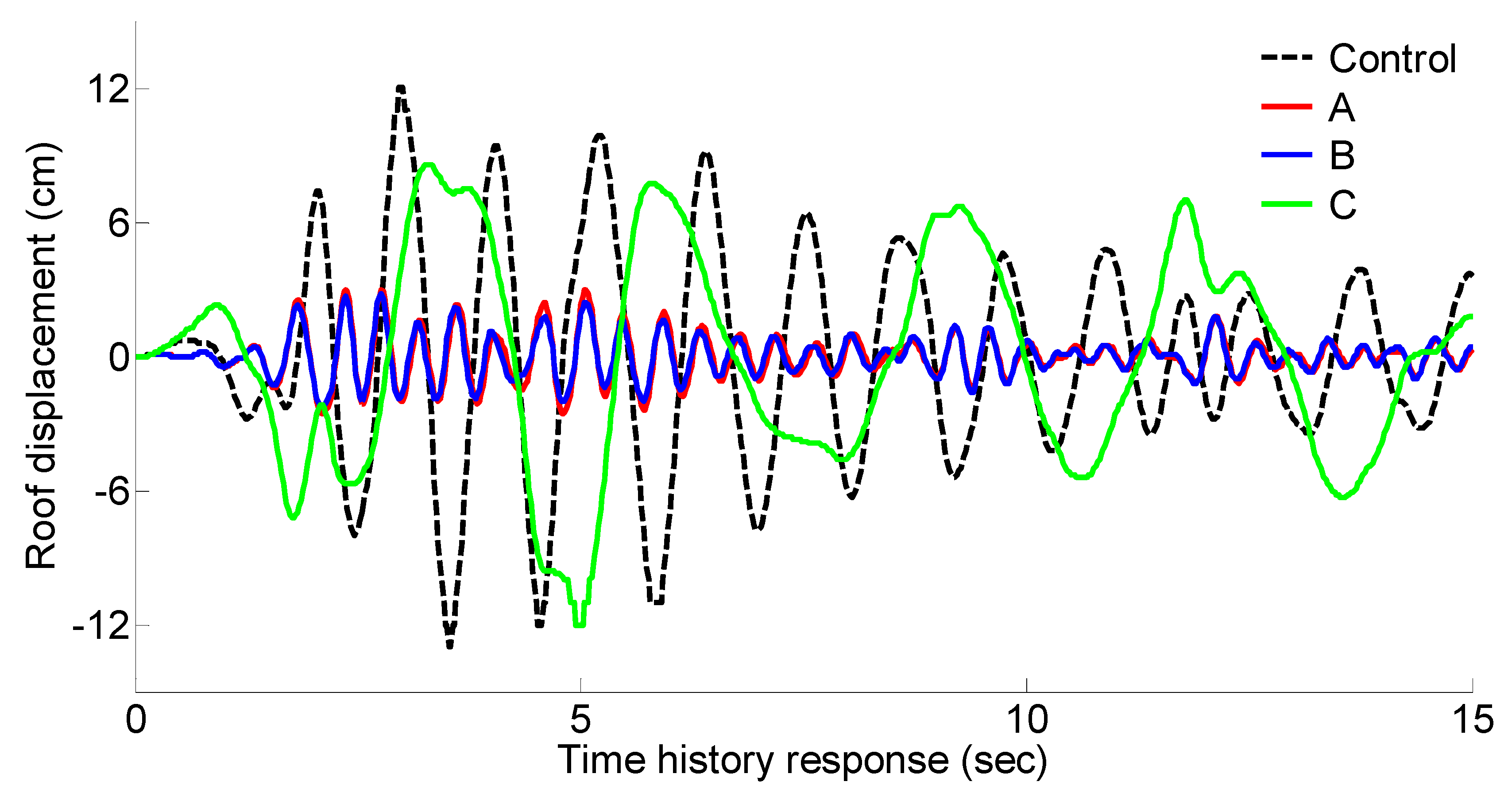
3.1. Seismic Performance

MATLAB [47] code was written for simulating the dynamic responses. Each of the cases constitutes a dynamic system, represented through a suitable set of equations of motion. These are defined by mass, damping, and stiffness matrices pertinent to the case’s attributes and the engineering assumptions. Five horizontal dynamic degrees of freedom were defined at each slab. They are numbered in increasing order, starting on the lowest slab.
For the control case, the mass and stiffness matrices are:
M c = ( 1904 0 0 0 0 0 1904 0 0 0 0 0 1904 0 0 0 0 0 1904 0 0 0 0 0 1332.8 ) , [ ton ]
K c = ( 1316.2 658.1 0 0 0 658.1 1316.2 658.1 0 0 0 658.1 1316.2 658.1 0 0 0 658.1 1316.2 658.1 0 0 0 658.1 658.1 ) ,   [ kN / mm ]
For Case 1:
M 1 = ( 2110.3 0 0 0 0 0 2110.3 0 0 0 0 0 2065.9 0 0 0 0 0 2065.9 0 0 0 0 0 1494.7 ) , [ ton ]
K 1 = ( 11,677 4120.1 61.5 17.6 31.2 4120.1 14,989 11,142 410.3 728.3 61.5 11,142 14,162 2618.9 583 17.6 410.3 2618.9 8675.9 5594.6 31.2 728.3 583 5594.6 5357 ) ,   [ kN / mm ]
and for Case 2:
M 2 = ( 2024.4 0 0 0 0 0 2110.3 0 0 0 0 0 2065.9 0 0 0 0 0 2065.9 0 0 0 0 0 1494.7 ) , [ ton ]
K 2 = ( 11,730 7874.3 34.9 3.52 44.5 7874.3 14,858 7064.9 6 75.6 34.9 7064.9 11,675 4784.2 138.7 3.52 6 4784.2 9285 4510.3 44.5 75.6 138.7 4510.3 4251.7 ) ,   [ kN / mm ]
In Case 3, the mass matrix is identical to the control case. The stiffness matrix, on the other hand, is modified due to the BIS devices that are implemented on the ground floor. Hence:
M 3 = M c
K 3 = ( 697.5 658.1 0 0 0 658.1 1316.2 658.1 0 0 0 658.1 1316.2 658.1 0 0 0 658.1 1316.2 658.1 0 0 0 658.1 658.1 ) ,   [ kN / mm ]
The accelerograms were scaled to a PGA of 0.3 g, in accordance with the peak design value defined in the Israeli standard [34]. This PGA has a probability of 90% to be the highest over a reference period of 50 years. Based on the above data, suitable state-space models were formulated and MATLAB’s lsim command [47] was used for obtaining the state trajectories.
As stated above, inter-story drift response is a common index of the lateral loading exerted on the columns during an earthquake. A summary of the peak inter-story drift responses in all four earthquakes is given in Table 7. In Case 3, the drift represents the lateral deformation of the columns on the ground floor, after offsetting the isolators’ contribution. It can be seen that all of the retrofits effectively reduce the inter-story drifts to small magnitudes, thereby keeping the elements’ response in the elastic zone. It can be seen from Table 7 that all four earthquakes provide similar inter-story trends. As such a resemblance was also observed in the other responses, only El Centro responses are provided hereafter. Figure 7 presents the time–history response of the roof displacement and base shear. High roof displacement was obtained in Case 3 due to the lateral flexibility of the isolators. Such a response was anticipated and reflects the proper operation of the isolation system rather than intensive vibration.
A substantial reduction was observed in Case 3’s base shear response, while there was an increase in Cases 1 and 2, demonstrating the superiority of Case 3. The increase in Cases 1 and 2 was a consequence of the shortening of the natural vibration periods, causing larger accelerations in response. This reflects the extensive retrofitting of the foundation system required in Cases 1 and 2 in order to allow it to bear the increased loads.
The maximal base isolation drift over the four earthquakes was 16 cm, caused during the Hachinohe accelerogram. This generated a shear strain of 81%, out of the allowable 260%.
Table 8 details the seismic performance assessment results by means of J 1 and J 2 .
According to the seismic analysis, all of the cases were found to be effective for enhancing the building’s safety during an earthquake. However, the most effective of them was Case 3, as it reduced the displacements and internal forces in the structure as well as the floors’ accelerations

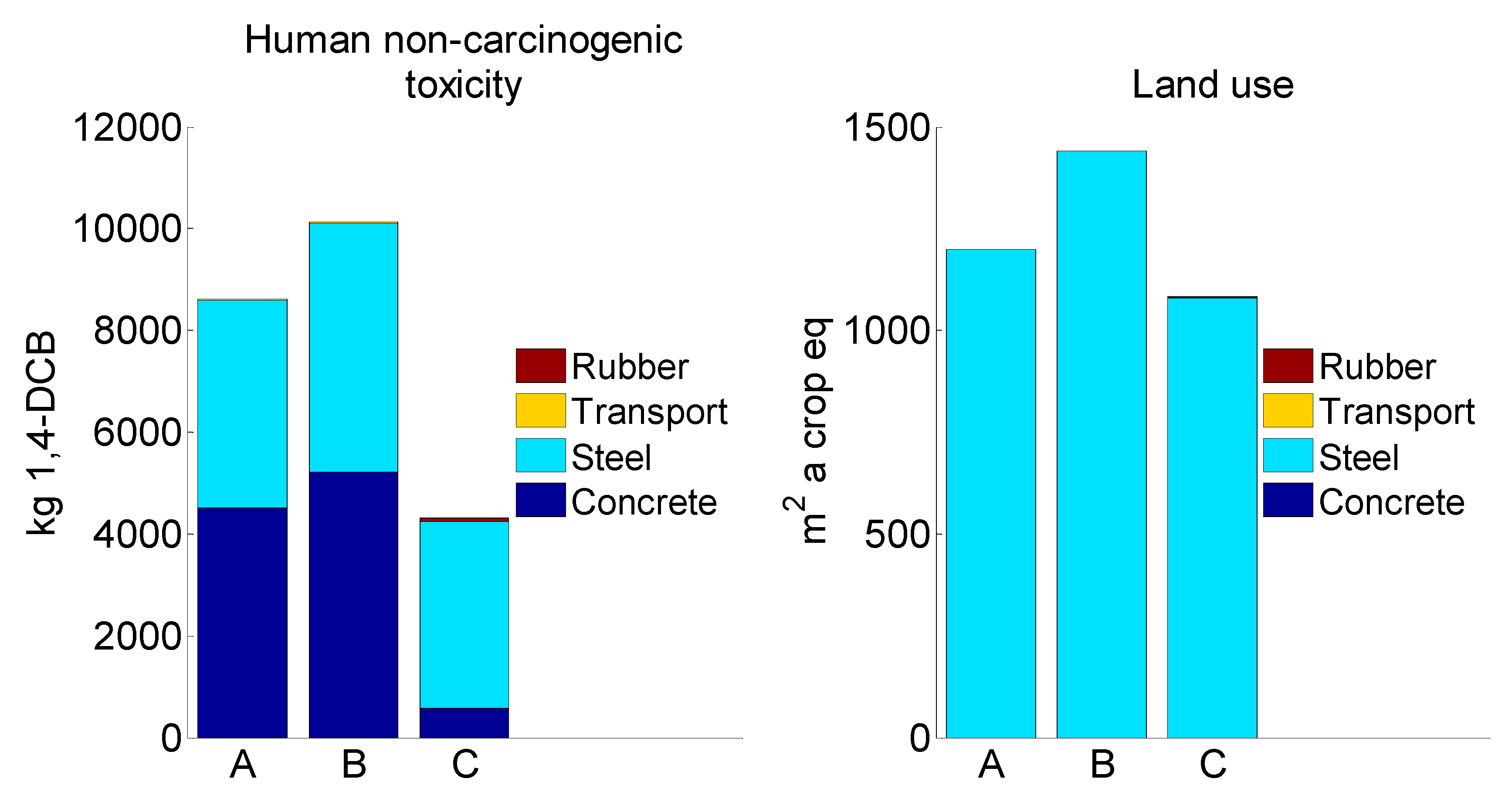
3.2. ReCiPe 2016 Midpoint Results

Figure 8 shows that Case 1 had the lowest water consumption; Case 3 had the lowest global warming potential, mineral resource scarcity, and fossil resource scarcity; and Case 2 had the highest global warming potential, mineral resource scarcity, and fossil resource scarcity.
Figure 9 shows that Case 3 had the lowest ionizing radiation, terrestrial ecotoxicity, human non-carcinogenic toxicity, and land use.
This difference in impact is due to the different quantities of concrete, steel, and rubber needed for the three retrofitting measures (Table 4). Cement is a well-known concrete component that releases high amounts of CO2 emissions during its production [48]. According to many studies, cement is the largest contributor of CO2 in concrete production; relative to the resulting global warming potential associated with concrete production, the share for cement was 74–93% [49,50,51]. Steel production is another high-energy process that has a great environmental impact [52]. The blast furnace process influences global warming potential (40%), abiotic depletion potential (35%), and human toxicity potential (17%) [53].
Therefore, due to the large quantities of concrete and steel used in Cases 1 and 2 (Table 4), these materials were the main contributors to the global warming potential of these two retrofitting measures. However, Case 3, which used the smallest quantity of concrete, was environmentally more attractive than Cases 1 and 2 when evaluating this impact (Figure 8). A similar effect of concrete was also observed for fossil resource scarcity due to the consumption of fossil fuels needed for the high-energy production processes of this material. Steel production requires iron ore depletion [53], thereby increasing mineral resource scarcity. In this respect, Case 3 is more attractive than Cases 1 and 2. The impact of water consumption mostly depended on the rubber for Case 3, making Case 1 and Case 2 more attractive. The impact of the transport component of global warming potential and the scarcity of fossil resources in Case 1 and Case 2 were more evident than in Case 3. This is due to the large amounts of concrete and steel for Case 1 and Case 2 that must be transported from suppliers to the construction site.
Ionizing radiation, terrestrial ecotoxicity, and human non-carcinogenic toxicity mostly depended on the concrete and steel components of the three studied retrofitting measures (Figure 9). Compared to Cases 1 and 2, Case 3 used less concrete, steel, and transport. As a result, Case 3 was more attractive than Cases 1 and 2 with regard to these impacts. Land use depended on the steel component (Figure 9). Compared to Cases 1 and 2, Case 3 used the lowest quantity of steel (Table 4). Therefore, Case 3 was also more attractive than Cases 1 and 2 when evaluating this impact.

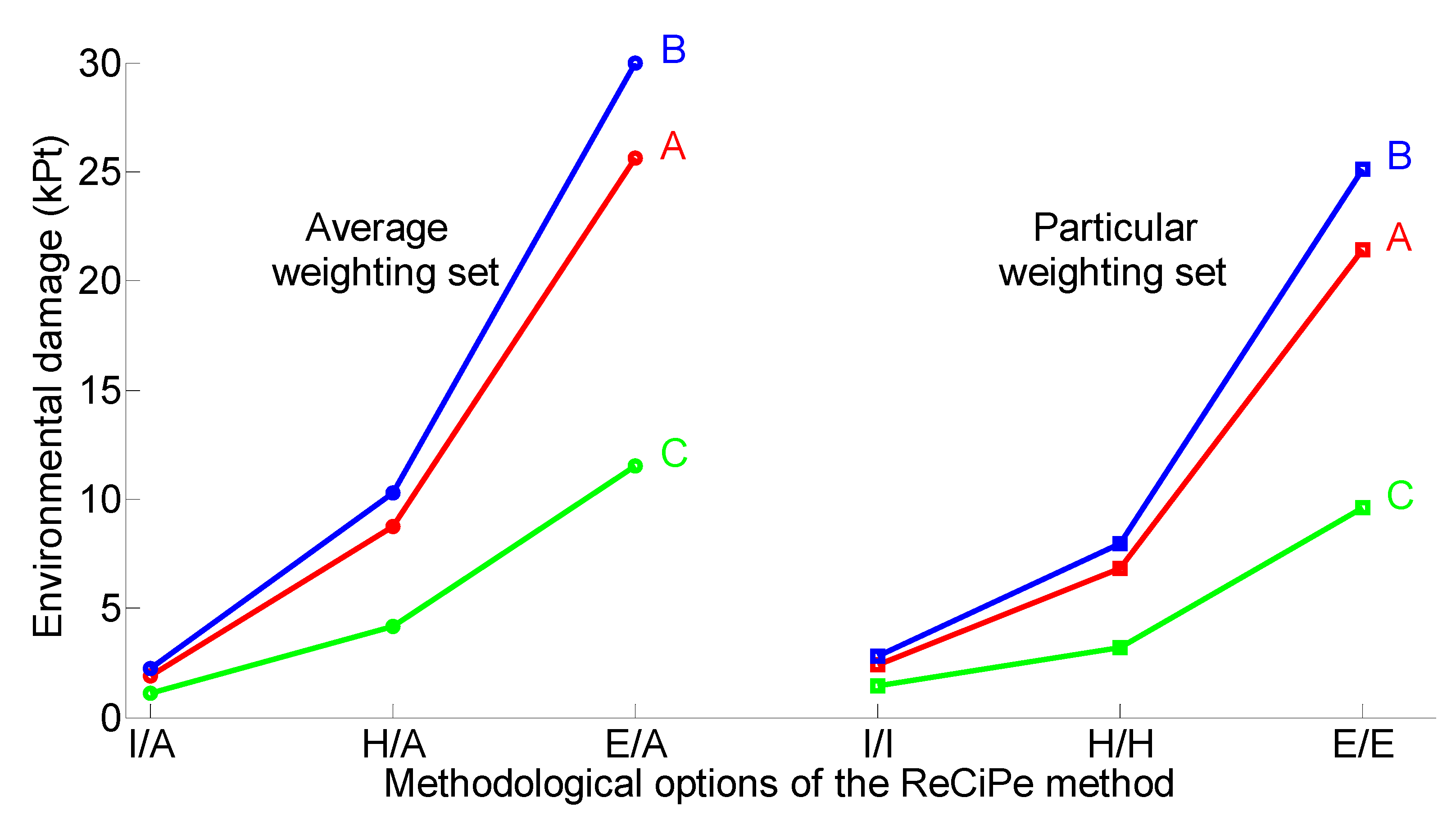
3.3. ReCiPe 2016 Endpoint Single-Score Results

Figure 10 shows the environmental damage of the three retrofitting measures via all methodological options of ReCiPe2016. Compared to Case 3, Cases 1 and 2 were more harmful. This was confirmed for six methodological options.
In particular, the difference between the cases was smallest for I/A and I/I (20-year period, short-lived pollutants), intermediate for H/A and H/H (100-year period, long-lived pollutants), and largest in E/A and E/E (1000-year time horizon, infinite living pollutants). This outlines the necessity of application of the ReCiPe2016 endpoint single-score results with an ANOVA, in which the six methodological options of ReCiPe2015 can be simultaneously evaluated [54,55].
Simultaneous evaluation of the six methodological options resulted in a negative difference between Case 1 and Case 2 and in positive differences between Case 1 and Case 3 and between Case 2 and Case 3 of the compared retrofitting measures (Table 9). This shows that Case 3 is the best measure when evaluating all impacts with the ReCiPe 2016 endpoint single-score method. Cases 1 and 2 were more damaging retrofitting measures with significantly equal environmental damage. It was found that the ecological preference of the three cases does not depend on the applied perspective with regard to different views on the importance of an environmental problem.

3.4. The Effect on the Parking Spots

Each of the retrofitting cases had different implications for the parking spaces. From the viewpoint of the environmental damage emanating from the consumption of materials, this factor was identical for Cases 1, 2, and 3. Therefore, it was omitted from the damage environmental analysis for not contributing to the environmental comparison. However, as explained above, blocking parking spots is a major practical issue in the seismic retrofitting of existing residential buildings. In this context, blocking fewer parking spots is a significant advantage. The original number of parking spots was 24. As shown in Figure 2, the addition of stiffening walls on the ground floor in Case 1 reduced the number of parking spaces by 12 and prevented their recreation inside the building’s perimeter. In Case 2, the original arrangement of parking spaces was retained. In Case 3, the dampers blocked only two parking spots, but they were recreated at another place, thereby maintaining the original number of parking spots inside the building’s perimeter. In this regard, Cases 2 and 3 are superior to Case 1, as they do not require the creation of new parking spots outside the structure’s perimeter. For example, finding new parking places can be quite complex when the building is located in a densely populated area.

4. Conclusions

In this study, we conducted environmental evaluations of three retrofitting measures: (i) concrete shear-wall strengthening (Case 1); (ii) RC column jacketing with shear-wall strengthening; and (iii) high-damping rubber bearing base isolation with viscous fluid damping devices (Case 3). The following was concluded:
  • Based on the seismic analyses, the three cases improved the retrofitted building’s seismic-bearing capacity, with a preference for Case 3 as the most effective method. However, the environmental damage caused by these three cases was completely different.
  • According to the ReCiPe 2016 midpoint results, the production of Case 3 caused the least damage to the environment, while the production of Case 2 caused the most damage to the environment; Case 1’s production caused moderate environmental damage.
  • According to the ReCiPe 2016 endpoint single-score results, the environmental damage in Case 3 was significantly lower than in Cases 1 and 2, which had significantly similar environmental damage.
Notably, because a variety of seismic and environmental factors are involved in these analyses, at this stage the conclusions should be considered as being specific to a local Israeli building, and they may not be pertinent to other countries. Additional investigations should be conducted to obtain more general results. However, the present results suggest that the environmental performance of retrofitting measures needs to be carefully considered.

Author Contributions

Conceptualization, S.P., I.H. and Y.R.; methodology, S.P., I.H. and Y.R.; software, S.P. and I.H.; validation, S.P., I.H. and Y.R.; formal analysis, S.P., I.H. and Y.R.; writing—original draft preparation, S.P. and I.H.; writing—review and editing, S.P., I.H. and Y.R. All authors have read and agreed to the published version of the manuscript.

Funding

This research received no external funding.

Data Availability Statement

Not applicable.

Conflicts of Interest

The authors declare no conflict of interest.

References

  1. Ribakov, Y.; Halperin, I.; Pushkar, S. Seismic resistance and sustainable performance of retrofitted buildings by adding stiff diaphragms or seismic isolation. J. Architect. Eng. 2018, 24, 04017028. [Google Scholar] [CrossRef]
  2. Margalit, T.; Mualam, T. Selective Rescaling, Inequality and Popular Growth Coalitions: The Case of the Israeli National Plan for Earthquake Preparedness. Land Use Policy 2020, 99, 105123. [Google Scholar] [CrossRef]
  3. Kaliyaperumal, G.; Sengupta, A.K. Seismic retrofit of columns in buildings for flexure using concrete jacket. ISET Earthq. Techn. J. 2009, 46, 77–107. [Google Scholar]
  4. Aguilar, J.; Juarez, H.; Ortega, R.; Iglesias, J. The Mexico Earthquake of September 19, 1985-Statistics of Damage and of Retrofitting Techniques in Reinforced Concrete Buildings Affected by the 1985 Earthquake. Earthq. Spectra 1989, 5, 145–151. [Google Scholar] [CrossRef]
  5. Sudha, C.; Sambasivan, A.K.; Rajkumar, P.R.K.; Jegan, M. Investigation on the performance of reinforced concrete columns jacketed by conventional concrete and geopolymer concrete. Eng. Sci. Technol. Int. J. 2022, 101275, in press. [Google Scholar] [CrossRef]
  6. Ribakov, Y.; Halperin, I.; Pushkar, S. Using Eco-indicator 99 and a two-stage nested analysis of variance test to evaluate building mitigation measures under hazard risks. Adv. Struct. Eng. 2016, 19, 860–870. [Google Scholar] [CrossRef]
  7. Halperin, I.; Ribakov, Y.; Agranovich, G. Optimal viscous dampers gains for structures subjected to earthquakes. Struct. Contr. Health Monit. 2016, 23, 458–469. [Google Scholar] [CrossRef]
  8. Tiwari, P.; Badal, P.; Suwal, R. Effectiveness of fluid viscous dampers in the seismic performance enhancement of RC buildings. Asian J. Civ. Eng. 2022. [Google Scholar] [CrossRef]
  9. Naeim, F.; Kelly, J.M. Design of Seismic Isolated Structures: From Theory to Practice, 1st ed.; John Wiley and Sons: Hoboken, NJ, USA, 1999. [Google Scholar]
  10. Chen, B.; Dai, J.; Song, T.; Guan, Q. Research and Development of High-Performance High-Damping Rubber Materials for High-Damping Rubber Isolation Bearings: A Review. Polymers 2022, 14, 2427. [Google Scholar] [CrossRef]
  11. Ribakov, Y. Reduction of structural response to near fault earthquakes by seismic isolation columns and variable friction dampers. Earthq. Eng. Engin. Vib. 2010, 9, 113–122. [Google Scholar] [CrossRef]
  12. Mori, C.; Sorace, S.; Terenzi, G. Seismic assessment and retrofit of two heritage listed R/C elevated water storage tanks. Soil Dyn. Earthq. Eng. 2015, 77, 123–136. [Google Scholar] [CrossRef]
  13. Jangid, R.; Kelly, J. Base Isolation for Near-fault Motions. Earthq. Eng. Struct. Dyn. 2001, 30, 691–707. [Google Scholar] [CrossRef]
  14. Saif, H.; Lee, D.; Retamal, E. Viscous Damping for Base-Isolated Structures, Taylor Devices. 1998. Available online: https://www.taylordevices.com/white-paper/36-viscous-damping-for-base-isolated-structures/ (accessed on 1 November 2022).
  15. Sorace, S.; Terenzi, G.; Magonette, G.; Molina, F.J. Experimental investigation on a base isolation system incorporating steel–Teflon sliders and pressurized fluid viscous spring dampers. Earthq. Eng. Struct. Dyn. 2008, 37, 225–242. [Google Scholar] [CrossRef]
  16. Mohebbi, M.; Noruzvand, M.; Dadkhah, H.; Shakeri, K. Direct displacement-based design approach for isolated structures equipped with supplemental fluid viscous damper. J. Build. Eng. 2022, 45, 103684. [Google Scholar] [CrossRef]
  17. Chen, X.; Xiong, J. Seismic resilient design with base isolation device using friction pendulum bearing and viscous damper. Soil Dyn. Earthq. Eng. 2022, 153, 107073. [Google Scholar] [CrossRef]
  18. Tsipianitis, A.; Tsompanakis, Y. Improving the seismic performance of base-isolated liquid storage tanks with supplemental linear viscous dampers. Earthq. Eng. Eng. Vib. 2022, 21, 269–282. [Google Scholar] [CrossRef]
  19. Mazza, F. Base-isolation of a hospital pavilion against in-plane-out-of-plane seismic collapse of masonry infills. Eng. Struct. 2021, 228, 111504. [Google Scholar] [CrossRef]
  20. Mazza, F. Seismic vulnerability and retrofitting by damped braces of fire-damaged R.C. framed buildings. Eng. Struct. 2015, 101, 179–192. [Google Scholar] [CrossRef]
  21. Mazza, F. Dissipative steel exoskeletons for the seismic control of reinforced concrete framed buildings. Struct. Contr. Health Monit. 2021, 28, e2683. [Google Scholar] [CrossRef]
  22. Sorace, S.; Terenzi, G. Non-linear dynamic design procedure of FV spring-dampers for base-isolation–frame building appications. Eng. Struct. 2001, 23, 1568–1576. [Google Scholar] [CrossRef] [Green Version]
  23. Stengel, T.; Schiessl, P. Life Cycle Assessment (LCA) of Ultra High Performance Concrete (UHPC) Structures. In Eco-Efficient Construction and Building Materials: Life Cycle Assessment (LCA), Eco-Labeling and Case Studies; Pacheco Torgal, F., Cabeza, L.F., Labrincha, J., DeMagalhaes, A., Eds.; Woodhead Publishing: Sawston, UK, 2014; Volume 49, pp. 528–564. [Google Scholar] [CrossRef]
  24. Van den Heede, P.; De Belie, N. Environmental impact and life cycle assessment (LCA) of traditional and ’green’concretes: Literature review and theoretical calculations. Cement Concr. Compos. 2012, 34, 431–442. [Google Scholar] [CrossRef]
  25. Wei, H.H.; Shohet, I.M.; Skibniewski, M.J.; Shapira, S.; Yao, X. Assessing the lifecycle sustainability costs and benefits of seismic mitigation designs for buildings. J. Archit. Eng. 2016, 22, 04015011. [Google Scholar] [CrossRef]
  26. Vitiello, U.; Salzano, A.; Asprone, D.; Di Ludovico, M.; Prota, A. Life-Cycle Assessment of Seismic Retrofit Strategies Applied to Existing Building Structures. Sustainability 2016, 8, 1275. [Google Scholar] [CrossRef] [Green Version]
  27. Salgado, R.A.; Apul, D.; Guner, S. Life cycle assessment of seismic retrofit alternatives for reinforced concrete frame buildings. J. Build. Eng. 2020, 28, 101064. [Google Scholar] [CrossRef]
  28. Welsh-Huggins, S.J.; Liel, A.B. A life-cycle framework for integrating green building and hazard-resistant design: Examining the seismic impacts of buildings with green roofs. Struct. Infrastruct. 2017, 13, 19–33. [Google Scholar] [CrossRef]
  29. Chopra, A.K. Dynamics of Structures: Theory and Applications to Earthquake Engineering; Prentice-Hall: Hoboken, NJ, USA, 1995. [Google Scholar]
  30. Briman, V.; Ribakov, Y. Using seismic isolation columns for retrofitting buildings with soft stories. Struct. Des. Tall Spec. Build 2009, 18, 507–523. [Google Scholar] [CrossRef]
  31. Spencer, B.F., Jr. Next Generation Benchmark Control Problems for Seismically Excited Buildings. In Proceedings of the 2nd World Conference on Structural Control, Kyoto, Japan, 28 June–1 July 1998; pp. 1335–1360. [Google Scholar]
  32. Antsaklis, P.J.; Michel, A.N. Linear Systems, 2nd ed.; Birkhäuser: Boston, MA, USA, 2006. [Google Scholar]
  33. Burl, J.B. Linear Optimal Control-H2 and H∞ Methods; Addison Wesley: Menlo Park, CA, USA, 1999. [Google Scholar]
  34. IS 413. Israeli Standard–413; Design Provisions for Earthquake Resistance of Structures. Standards Institute of Israel: Tel-Aviv, Israel, 1998. (In Hebrew)
  35. ISO 13315-1; Environmental Management for Concrete and Concrete Structures, Part. 1: General Principles. International Organization for Standardization: Geneva, Switzerland, 2012.
  36. Martin, J. Long Term Performance of Rubber in Seismic and Non-Seismic Bearings: A Literature Review; U.S. Department of Commerce National Institute of Standards and Technology, Building and Fire Research Laboratory: Galthenburg, MD, USA, 1991; p. 20899.
  37. Napolano, L.; Menna, C.; Asprone, D.; Prota, A.; Manfredi, G. Life cycle environmental impact of different replacement options for a typical old flat roof. Int. J. Life Cycle Assess. 2015, 20, 694–708. [Google Scholar] [CrossRef]
  38. Scheuer, C.; Keolian, G.; Reppe, B. Life cycle energy and environmental performance of a new university building: Modeling challenges and design implications. Energy Build. 2003, 35, 1049–1064. [Google Scholar] [CrossRef]
  39. ISO 14040; Environmental Management Life Cycle Assessment Principles and Framework. International Organization for Standardization: Geneva, Switzerland, 2006.
  40. Bilec, M.M.; Ries, R.J.; Matthews, H.S. Life-cycle assessment modeling of construction processes for buildings. J. Infrastruct. Syst. 2010, 16, 199–205. [Google Scholar] [CrossRef]
  41. SimaPro, Version 9.0; PRé Consultants: Amersfoort, The Netherlands, 2019; Available online: https://simapro.com/ (accessed on 15 September 2022).
  42. Huijbregts, M.A.J.; Steinmann, Z.J.N.; Elshout, P.M.F.; Stam, G.; Verones, F.; Vieira, M.; Zijp, M.; Hollander, A.; van Zelm, R. ReCiPe2016: A harmonised life cycle impact assessment method at midpoint and endpoint level. Int. J. Life Cycle Assess. 2017, 22, 138–147. [Google Scholar] [CrossRef]
  43. Picquelle, S.J.; Mier, K.L. A practical guide to statistical methods for comparing means from two-stage sampling. Fish Res. 2011, 107, 1–13. [Google Scholar] [CrossRef]
  44. Pushkar, S. The Effect of Different Concrete Designs on the Life-Cycle Assessment of the Environmental Impacts of Concretes Containing Furnace Bottom-Ash Instead of Sand. Sustainability 2019, 11, 4083. [Google Scholar] [CrossRef] [Green Version]
  45. Pushkar, S. Modeling the substitution of natural materials with industrial byproducts in green roofs using life cycle assessments. J. Clean. Prod. 2019, 227, 652–661. [Google Scholar] [CrossRef]
  46. Hurlbert, S.H.; Lombardi, C.M. Final collapse of the Neyman-Pearson decision theoretic framework and rise of the neoFisherian. Ann. Zool. Fenn 2009, 46, 311–349. Available online: https://www.jstor.org/stable/23736900 (accessed on 20 April 2022).
  47. MATLAB; [Computer software]. MathWorks: Natick, MA, USA, 2022.
  48. Chen, C.; Habert, G.; Bouzidi, Y.; Jullien, A. Environmental impact of cement production: Detail of the different processes and cement plant variability evaluation. J. Clean. Prod. 2010, 18, 478–485. [Google Scholar] [CrossRef]
  49. O’Brien, K.R.; Ménaché, J.; O’Moore, L.M. Impact of Fly Ash Content and Fly Ash Transportation Distance on Embodied. Greenhouse Gas Emissions and Water Consumption in Concrete. Int. J. Life Cycle Assess. 2009, 7, 621–629. [Google Scholar] [CrossRef] [Green Version]
  50. Celik, K.; Meral, C.; Petek Gursel, A.; Mehta, P.K.; Horvath, A.; Monteiro, P.J.M. Mechanical Properties, Durability, and Life-Cycle Assessment of Self-Consolidating Concrete Mixtures Made with Blended Portland Cements Containing Fly Ash and Limestone Powder. Cem. Concr. Compos. 2015, 56, 59–72. [Google Scholar] [CrossRef] [Green Version]
  51. Gursel, A.P.; Ostertag, C. Impact of Singapore’s importers on life-cycle assessment of concrete. J. Clean. Prod. 2016, 118, 140–150. [Google Scholar] [CrossRef]
  52. Conejo, A.N.; Birat, J.-P.; Dutta, A. A review of the current environmental challenges of the steel industry and its value chain. J. Environ. Manag. 2020, 259, 109782. [Google Scholar] [CrossRef]
  53. Liang, T.; Wang, S.; Lu, C.; Jiang, N.; Long, W.; Zhang, M.; Zhang, R. Environmental impact evaluation of an iron and steel plant in China: Normalized data and direct/indirect contribution. J. Clean. Prod. 2020, 264, 121697. [Google Scholar] [CrossRef]
  54. Pushkar, S. Using Eco-Indicator 99 to Evaluate Building Technologies under Life Cycle Assessment Uncertainties. J. Architect. Eng. 2014, 20, 04013010-1-10. [Google Scholar] [CrossRef]
  55. Pushkar, S. Life Cycle Assessment of Flat Roof Technologies for Office Buildings in Israel. Sustainability 2016, 8, 54. [Google Scholar] [CrossRef]
Figure 1. Concrete shear walls: two types of wall distribution (Case 1).
Buildings 12 01854 g001
Figure 2. Reinforced concrete columns jacketing with shear walls strengthening (Case 2).
Buildings 12 01854 g002
Figure 3. High-damping rubber bearing base isolation with viscous fluid damping devices (Case 3).
Buildings 12 01854 g003
Figure 4. Arrangement of the parking spots in each of the cases.
Buildings 12 01854 g004
Figure 5. Comparison of the natural frequencies and damping ratios of each mode of vibration: (A) Case 1, (B) Case 2, and (C) Case 3.
Buildings 12 01854 g005
Figure 6. Two-stage analysis of variance (ANOVA) hierarchical design structure for environmental evaluation of Cases 1 and 2 (ReCiPe 2016 single-score evaluations [42]).
Buildings 12 01854 g006
Figure 7. Base shear and roof displacement time–history responses for the El Centro earthquake: (A) Case 1, (B) Case 2, and (C) Case 3.
Buildings 12 01854 g007aBuildings 12 01854 g007b
Figure 8. (A) Case 1, (B) Case 2, and (C) Case 3 evaluated with the ReCiPe 2016 midpoint method [42].
Buildings 12 01854 g008
Figure 9. (A) Case 1, (B) Case 2, and (C) Case 3 evaluated with the ReCiPe 2016 midpoint method.
Buildings 12 01854 g009aBuildings 12 01854 g009b
Figure 10. Environmental damage from three retrofitting measures—(A) Case 1, (B) Case 2, and (C) Case 3—evaluated using the ReCiPe 2016 endpoint single-score method.
Buildings 12 01854 g010
Table 1. Shear wall distribution in Cases 1 and 2.
FloorCase 1Case 2
GroundType I-
1Type IType I
2Type IIType I
3Type IIType II
4Type IIType II
Table 2. Effective modal masses, as percentages of the total mass.
ModeControl CaseCase 1Case 2Case 3
188.3%82.14%91.26%99.93%
28.61%10.24%7.3%0.07%
32.3%7.46%1.07%-
40.66%0.11%0.24%-
50.13%0.05%0.13%-
Note: Negligible values were omitted in Case 3.
Table 3. Accelerogram data for the El Centro, Hachinohe, Kobe, and Northridge records that were used in this study.
ModeEl CentroKobeHachinoheNorthridge
Earthquake nameImperial ValleyKobeTokachi-okiNorthridge
Date (UTC)18 May 194016 January 199516 May 196817 January 1994
Magnitude6.9 Mw6.9 Mw8.3 Mw6.7 Mw
StationEl Centro (No. 117)KJMAHachinohe PortSylmar, county hospital parking lot
Epicentral distance11.5 km14.6 km158 km15.3 km
Original PGA0.349 g0.82 g0.23 g0.84 g
Scaled PGA0.3 g0.3 g0.3 g0.3 g
Record’s duration50.02 s59.98 s36.01 s60.02 s
Note: The scaled PGA is the one used in this study.
Table 4. Material consumption in Cases 1, 2, and 3.
Retrofitting MeasureMaterial per Retrofitting Measure (tons)
ConcreteSteelRubber
Case 1Shear walls58716.6-
Circumferential beams40111.4-
Foundations86428.6-
Total185256.6-
Case 2Columns’ jacketing521.5-
Shear walls48916.6-
Circumferential beams40111.4-
Foundations120138.5-
Total214268-
Case 3Isolators-40.22.59
Dampers6.71.6-
Columns’ jacketing19.70.7-
Foundations2058.6-
Total231.451.12.59
Note: The concrete density was taken as 2500 kg/m3 and that of the steel was taken as 7800 kg/m3. The concrete amounts were increased by 10% to include construction losses. The mass of the isolator’s rubber was computed by offsetting the steel’s mass in each isolator from its overall mass.
Table 5. Life-cycle inventory (LCI) for Cases 1–3: references from the EcoInvent v3.2 database.
Material/ProcessReference
ConcretePre-cast concrete, production mixture C 20/25/RER U
SteelSteel rebar/EU
RubberAcrylonitrile–butadiene–styrene copolymer, ABC, at plant/RER U
TransportationLorry transport, Euro 0, 1, 2, 3, 4 mix, 22 t total weight, 17.3 t
Table 6. Life-cycle impact assessment (LCIA) of Cases 1–3 (EcoInvent v3.2 database and ReCiPe2016 midpoint H evaluation).
Material/ProcessConcrete
(1 kg)
Steel
(1 kg)
Rubber
(1 kg)
Transport
(1 tkm)
GWP (kg CO2)0.1222.314.730.376
MRS (kg Cu eq)-0.049--
FRS (kg oil eq)0.009510.471--
WC (m3)0.00004380.002460.6880.225
IO (kBq Co-60 eq)0.001430.003710.04390.047
TE (kg 1,4-DCB)0.02570.3810.8211.14
HNCT (kg 1,4-DCB)0.002440.07180.02560.0813
LU (m2 a crop eq)-0.02110.00166-
Note: GWP, global warming potential; MRS, mineral resource scarcity; FRS, fossil resource scarcity; WC, water consumption; IO, ionizing radiation; TE, terrestrial ecotoxicity; HNCT, human non-carcinogenic toxicity; LU, land use; 1,4-DCB, 1,4-dichloro-benzine equivalent.
Table 7. Peak inter-story drifts in mm for each of the earthquakes: El Centro, Hachinohe, Kobe, and Northridge.
FloorControlCase 1Case 2Case 3
El CentroHachinoheKobeNorthridgeEl CentroHachinoheKobeNorthridgeEl CentroHachinoheKobeNorthridgeEl CentroHachinoheKobeNorthridge
1364348476799101417196958
23239443710121516567861058
330343531455656786857
422282626911121457794645
510151213344534452222
Table 8. Seismic performance evaluation by means of J1 and J2.
CaseJ1J2
Case 10.321.62
Case 20.341.58
Case 30.280.27
Table 9. The p-values from three retrofitting measures—(A) Case 1, (B) Case 2, and (C) Case 3—evaluated using the ReCiPe 2016 endpoint single-score method.
CaseABC
AX0.08070.0044
B X0.0030
C X
Note: Bold font: seems to be positive; regular font: seems to be negative.
Publisher’s Note: MDPI stays neutral with regard to jurisdictional claims in published maps and institutional affiliations.

