Article

Numerical Simulation Methodology for Prefabricated Shear Walls Considering Stochastic Defects in Grouting Materials

1
School of Civil Engineering, Suzhou University of Science and Technology, Suzhou 215011, China
2
School of Civil Engineering, Southeast University, Nanjing 210096, China
*
Authors to whom correspondence should be addressed.
Buildings 2022, 12(11), 1859; https://doi.org/10.3390/buildings12111859
Submission received: 7 October 2022 / Revised: 14 October 2022 / Accepted: 31 October 2022 / Published: 2 November 2022

Abstract

:
The most used connection form for reinforced steel bars is the grouting sleeve using cement-based grouting materials. Hence, the quality of the grouting sleeve connection determines whether the performance of a precast concrete structure is equivalent to that of a cast in situ concrete structure. However, several existing reasons, namely, insufficient grouting cement or poor construction controls and even stochastic bubble holes, lead to inevitable grouting defects. The behavior of precast concrete structures is affected dramatically. Considering the cost and efficiency of the analysis of precast concrete structures, the finite element method is still the most used method, but the simulation technology of structures considering stochastic defects in grouting materials is not sufficient. Herein, a simulation method considering stochastic defects in precast concrete structures is proposed, and the application of the method to grouting sleeves and shear wall structures is performed to verify its accuracy and feasibility. The construction of stochastic defects in grouting material is first realized through the Python scripter. Secondly, the mechanical parameters are obtained from the refined finite element analysis of grouting sleeves with material defects. Finally, based on the obtained mechanical properties of grouting sleeves, the behaviors of precast shear walls under blast loading are analyzed. The simulations of grouting sleeves under uniaxial tensile loading and precast concrete shear walls under blast loading both indicate that the proposed numerical method is feasible in solving the structural issues with stochastic defects in grouting materials.

1. Introduction

Green, intelligent, and information-based construction is the research frontier all over the world currently. As a kind of green structure, precast concrete structures, with the advantages of low carbon emissions and efficient construction, have been widely used in construction systems, which is and will be the world’s mainstream future construction industrialization [1,2,3,4,5,6]. The core technology of precast concrete structures is the connection between individual components, and after that, the high-quality joints enable effective force transfer to provide bearing capacity and ductility [7,8,9,10,11,12]. Hence, the quality of the connection determines whether the performance of a precast concrete structure is equivalent to that of the cast in situ concrete structure. At present, the most used connection form for reinforced steel bars is the grouting sleeve using cement-based grouting materials. However, several reasons, such as insufficient grouting cement, unreasonable increases in the water–cement ratio, poor construction controls, and even stochastic bubble holes, lead to inevitable grouting defects, which directly affect the performances of precast concrete structures [13,14].
One of the methods to ensure the quality of the grouting sleeve connection is non-destructive testing (NDT) technology [15]. Based on NDT results, the grouting plumpness is evaluated, or reinforcement measures are proposed over time. Li and Liu [16] pointed out the influence of defects in grouting materials on grout sleeves, and the detection method was still insufficient. An ultrasonic guided-wave method was applied to test the defects in grouting materials, and damage index values were put forward. Liu et al. [17] proposed an ultrasonic imaging method for inspecting the grouted splice sleeves in PC structures using the reverse time migration (RTM) algorithm based on an elastic wave equation. Xu et al. [18] proposed a direct stress wave measurement to detect the defects in grouted splice sleeve connectors, and piezoelectric-lead-zirconate-titanate patches were applied as sensors. The feasibility of the proposed approach was validated by four specimens with different defect levels. Although NDTs provide the defect levels, the performance or the behavior of structures with defects in grouting sleeves could still not be evaluated.
The most effective and visual method to assess the behavior of precast concrete structures with defects in sleeves is the laboratory experiment. Guo et al. [13] researched the mechanical properties of the full-grouted sleeve connections with different defects based on a tension experiment. Only two kinds of defects, namely, insufficient grouting material strength and grouting plumpness, were considered. The influences on the tensile strength and elongation were decreased. Xu et al. [19] conducted an experiment on 126 half-grouted sleeve connection specimens with insufficient grouting configurations to evaluate the influence of defects on the failure modes and stress–slip curves. A stress–slip empirical model, which is useful to assess the performance of precast concrete structures with different defect levels, was proposed. Zheng et al. [20] considered vertical grouting defects in grouting sleeves and conducted experiments on 24 specimens under uniaxial tensile loading, high stress, and large-strain cyclic loading, respectively. The failure mode shifted from the tensile fracture of steel bars to the interfacial bond-slip failure. Guo et al. [21] indicated that the various defects in the grouted sleeve connections significantly decreased the precast concrete structure performances. A uniaxial tensile experiment on 42 connections considering multiple kinds of defects was examined and the mechanical properties were compared. Xiao et al. [22] considered the different sizes and positions of defects in grouting sleeves and investigated their influence on the seismic performance of shear walls. A cyclic loading experiment on precast concrete shear walls with defects of different characteristics was performed, and a monolithic cast-in-place wall was compared simultaneously. The loss of seismic performance was evident. Guo et al. [23] conducted a uniaxial tension experiment on 24 specimens considering six different situations of defects in half grouting sleeves. The influences on the tension behaviors and failure modes were explored. Li et al. [24] investigated the seismic performances of four two-story precast concrete frames with grouting defects in columns based on the reversed cyclic loading test. Although the collapse mechanism remained unchanged, the load capacity, stiffness, ductility, and energy absorption were reduced by the defects. Li et al. [25] investigated the seismic performance of prefabricated columns with the defects of semi-grouted sleeve connections. The defects were controlled by changing the length of the anchor bars. The existence of defects reduces the seismic behavior, such as the bearing capacity and energy dissipation ability of the assembled columns. From the aforementioned research, the experimental method seems to be the most used method to analyze the performance of structural elements, joints, and different structures with defects in grouting sleeves. From the perspective of cost, a large number of tests using elements to clarify the influences, especially structures with different defects, could not be realized. Hence, a more effective and cost-saving method should be applied to this engineering issue.
Nowadays, the finite element method [26] is the cheapest and most used approach in structural analysis, let alone the analysis of structures with defects in grouting sleeves. Yao et al. [27] used the echo method and the finite element method to study the internal condition of grouting sleeves. Qiao et al. [28] studied the seismic performance of the inverted exposed grouted sleeve (IEGS) column base joints through experiments and the finite element method. Yan et al. [29] conducted experiments on three different kinds of shear walls and analyzed the influences on seismic performance. Then, a finite element analysis was performed based on the different contact elements in the software of ABAQUS. Kahama et al. [30] analyzed the influences of defects on the performance of the full-grouted sleeve connections based on the numerical method. A friction-based interfacial model was established, and a parametric analysis of defects with 50 different contact surface interactions. The minimum anchorage length, which is eight times the diameter of the steel bar, was proposed.
Existing research on the defects in grouting materials assumes a regional or consecutive distribution either in simulations or in experiments. Hence, the modeling of defects in grouting sleeves usually uses the software functions of contacting elements or the hypothetical friction-based interfacial model. Sometimes, however, the distribution of defects is discontinuous or even stochastic. In particular, for most prefabricated engineering structures, the grouting plumpness is determined by random bubbles or small holes, which are difficult to simulate using the aforementioned simulation methods. Therefore, a more reasonable simulation strategy considering the small and random defects in grouting materials should be proposed to tackle this issue.
In this paper, a simulation method considering stochastic defects in precast concrete structures is proposed, and the application of the method to grouting sleeves and shear wall structures is performed to verify its accuracy and feasibility. Based on ABAQUS software, the simulation of stochastic defects in grouting materials is realized first, and then the mechanical parameters are obtained from the refined finite element analysis of grouting sleeves with material defects. Using the obtained mechanical parameters of grouting sleeves, we perform the analysis of a precast shear wall under different loadings. Section 2 illustrates the simulation procedure of stochastic defects in grouting materials. Based on the simulation technology, Section 3 performs a finite element analysis of grouting sleeves with random defects, and the experimental results are compared with the simulation results. In Section 4, the behavior of a precast shear wall considering defects in grouting sleeves under blast loading is analyzed to verify the feasibility of the proposed method. Several conclusions and expectations are drawn in Section 5.

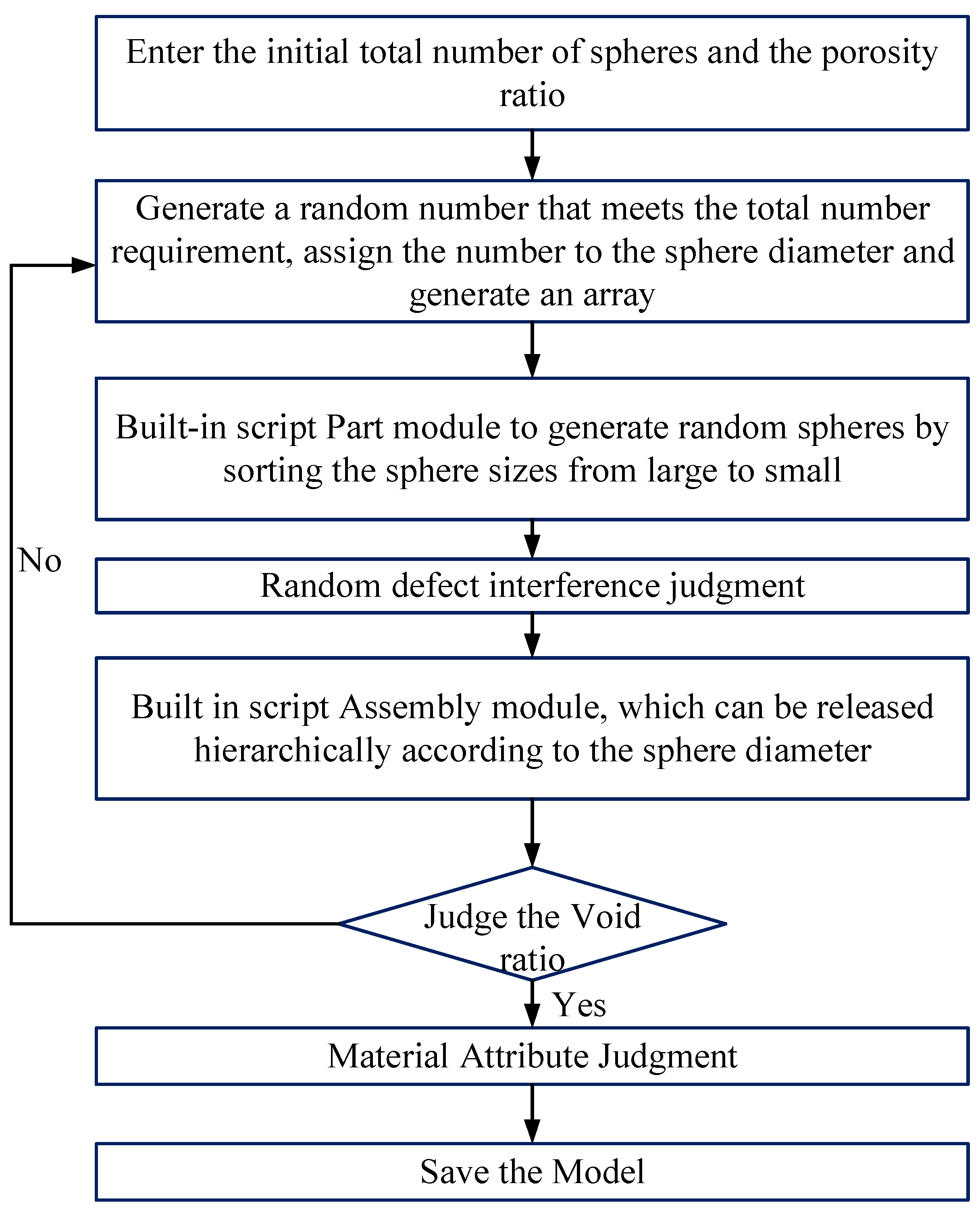
2. Simulation of Three-Dimensional Random Defects in Grouting Materials

The grouting material inside the sleeve may have defects such as grout leakage, air holes, impurities, and holes, and the geometric sizes and locations of the defects are usually highly random and non-uniform. In order to facilitate the performance evaluation of components or structures with grouting material defects, it is necessary to build a three-dimensional meso model of grouting materials by considering random defects. In this paper, a construction method replacing random defects with random sphere simulation was realized based on ABAQUS software and the PYTHON script program. The flowchart of the construction method of three-dimensional random defects in grouting material is shown in Figure 1, and the specific steps are as follows:
(a) Set the initial parameters. In order to simulate the defects of grouting materials, the total number of spheres simulating the defects in grouting materials, N, and the volume ratio of the defects shall be determined first.
(b) Generate the defect grading. The logarithmic normal distribution function close to the pore size distribution (Python random.lognormvariable) is selected to generate N random numbers.
(c) Assign the sphere diameter. We use the module Part built in the ABAQUS script interface to read the N random numbers of step (b) and assign them to N spheres as the diameter of the sphere, and form a randomly arranged sequence of spheres to be released, as shown in Figure 2.
(d) Release the sequence of spheres. We release the sphere through the ASSEMBLY module in the ABAQUS script interface and use the built-in random function to generate the first point in the model area for release. The defect sphere is allowed to coincide with the boundary of the model during delivery, which is closer to the real defect distribution. The second nth spheres are put in sequence. When placing the ith sphere, in addition to the boundary judgment, the judgment statement of the random sphere contact interference should also be written, that is “the distance between two spherical centers is greater than the difference of spherical radius”. If the interference judgment requirements are met, the ASSEMBLY module can be called. The partial coincidence of the spheres is allowed, but the complete coincidence of the spheres is not allowed. To ensure the effectiveness of defect placement, whether the ith sphere and the (i-1)th sphere are completely overlapped should be judged in sequence. If the spheres are completely coincident, it is necessary to generate a new random release coordinate point to release them again.
(e) Judge the volume ratio of the defects. We calculate the volume content of the sphere. If the volume ratio requirement is not met, we return to step (b) to regenerate the random sphere.
(f) Save the model. When the volume ratio requirements are met, an initial defect model is formed, as shown in Figure 3a. The random sphere is defined as null through Boolean operation, then the defect model is built, and the respective material attributes are given, as shown in Figure 3b.

3. Simulation and Analysis of Grouting Sleeves Considering Random Defects of Grouting Materials

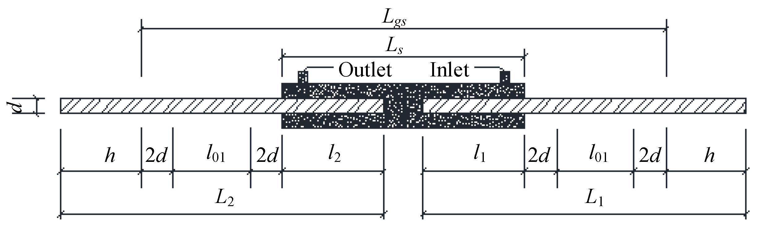
3.1. Model Parameters and Establishment

Five groups of grouting sleeves with different reinforcement diameters and anchorage lengths were set up [31] and a refined finite element simulation was carried out to study the influence of reinforcement diameters and anchorage lengths on grouting sleeves under the same defect conditions. Among them, HRB400 reinforcement was used, with diameters of 14 mm, 16 mm, and 18 mm, anchorage lengths of 8d, 5d, and 4d, a sleeve diameter of 39 mm, a wall thickness of 3.5 mm, and a length of 330 mm, respectively. The specific parameters of the specimens are shown in Figure 4 and Table 1, where d is the diameter of the reinforcement, h is the clamping length, l01 is the gauge length, l1 is the anchorage length of the reinforcement in the grouting section, L1 is the anchorage length of the reinforcement in the grouting section, l2 is the anchorage length of the reinforcement in the grouting section, L2 is the reinforcement length in the grouting section, Ls is the sleeve length, and Lgs is the parallel length of the specimen. When the specimen is numbered, the middle parameter indicates the diameter of reinforcement, and the end parameter indicates the anchorage length. Two different grouting material defects were considered, namely the 5% volume defect and the 10% volume defect, as shown in Figure 5.
The refined finite element analysis of grouting sleeves was carried out based on ABAUQS software. The concrete damage plasticity (CDP) model was selected as the material constitutive model of grouting materials, and the double broken line dynamic hardening model was selected as the material constitutive model of reinforcements and sleeves [20]. The CDP model parameters of grouting materials and the material parameters of reinforcements and sleeves are shown in Table 2 and Table 3, respectively. Considering the influence of an irregular distribution on grid generation in the defect simulations, the pixel grid method was used to generate the finite element grid for the grouting material model, the sweep grid generation method (Sweep) was used to generate the finite element grid for the reinforcements and sleeves, and the interfaces nodes between the reinforcement and grouting material and between the sleeve and grouting material were merged. In the finite element model, C3D8R units were used for reinforcements, grouting materials, and sleeves. The grid division of the model is shown in Figure 6. The grid divisions of grouting materials with different defect contents are shown in Figure 7, in which the numbers of grouting material units with 5% and 10% random defects are 174,347 and 165,238, respectively. During the loading simulation, Reference Point 1 (RP1) and Reference Point 2 (RP2) were set at the center of the reinforcement end section of the grout discharge region and the grouting section, respectively, and the reference points were coupled to the corresponding steel bar end sections, respectively. Displacement load was applied at RP1, and RP2 was set as consolidation to achieve quasi-static tensile simulation.

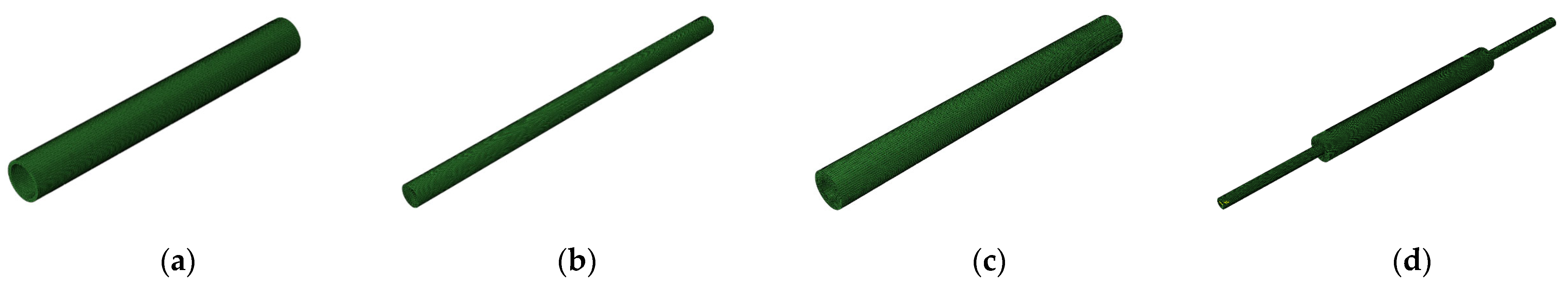
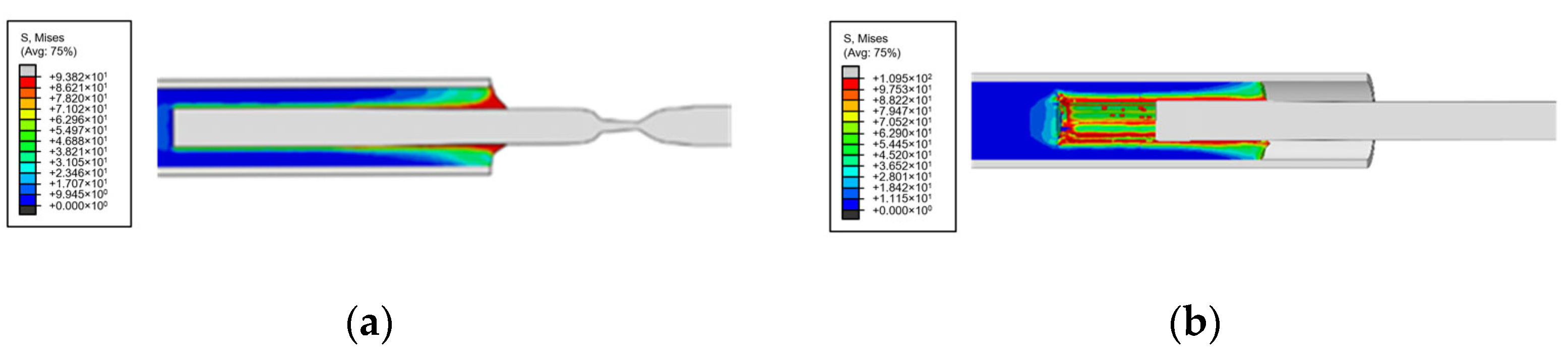
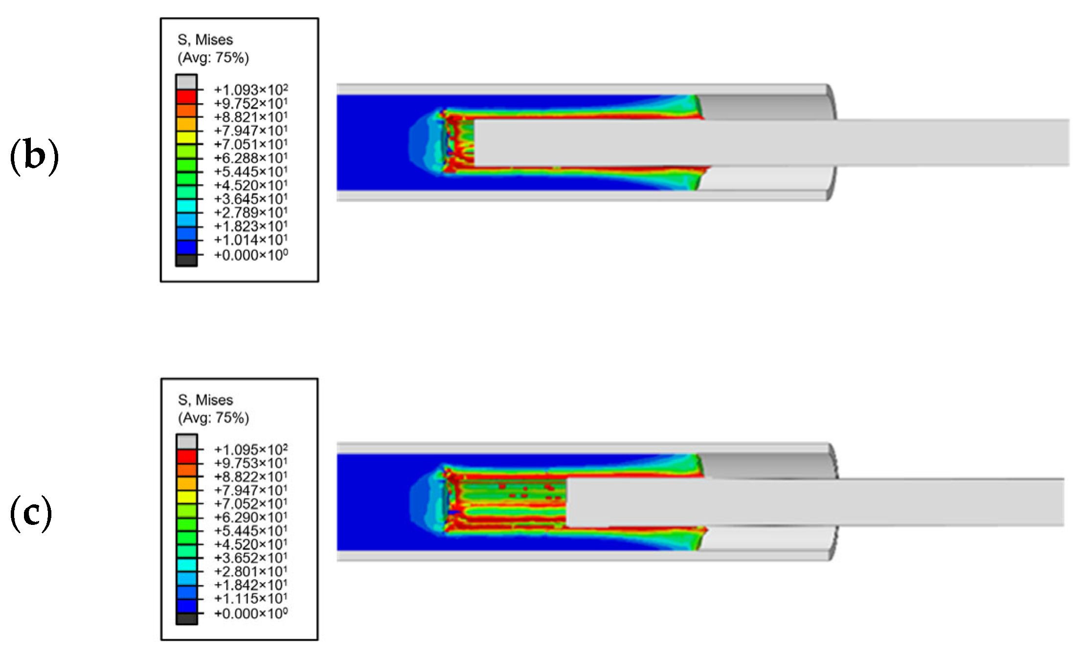
3.2. Verification of the Finite Element Models

According to Reference [31], for Specimen GS16-8d, the finite element models of the grouting sleeves with no defects and 25% defects at the end were established, respectively, as shown in Figure 8, and compared with the corresponding test results. For the above two defects, the failure modes and load–displacement curves of the grouting sleeves without and with defects are shown in Figure 9 and Figure 10, respectively.
For grouting sleeves without defects, the steel bars enter the necking stage after reaching the ultimate load, the bearing capacity decreases, and the steel bars break in tension, as shown in Figure 9a. The load–displacement curve obtained from the simulation is well-matched to the test results, and the yield and ultimate loads of steel bars are basically consistent with the test values [31]. For grouting sleeves with 25% defects at the end, the failure modes in the tensile test and simulation are both pullout failures of steel bars, as shown in Figure 9b, and the simulated load–displacement curve is also in good agreement with the test curve. Moreover, the numerical model can show the process of steel bar pullout failure, as shown in Figure 11.
It can be seen from Figure 10 that after reaching the ultimate load, the load decreases rapidly, and there are certain errors between the simulation results and the test results. This is because the unit deletion function is used for the grouting material in the CDP model, and the unit that reaches critical failure is automatically deleted, resulting in the rapid reduction of the mechanical bond force and friction between the bars and the grouting material. In the actual tensile test, there is still a certain bonding force and friction between the grouting material and the reinforcement when the reinforcement is pulled out. In conclusion, the numerical model can basically realize the performance simulation of the reinforcement grouting sleeve.

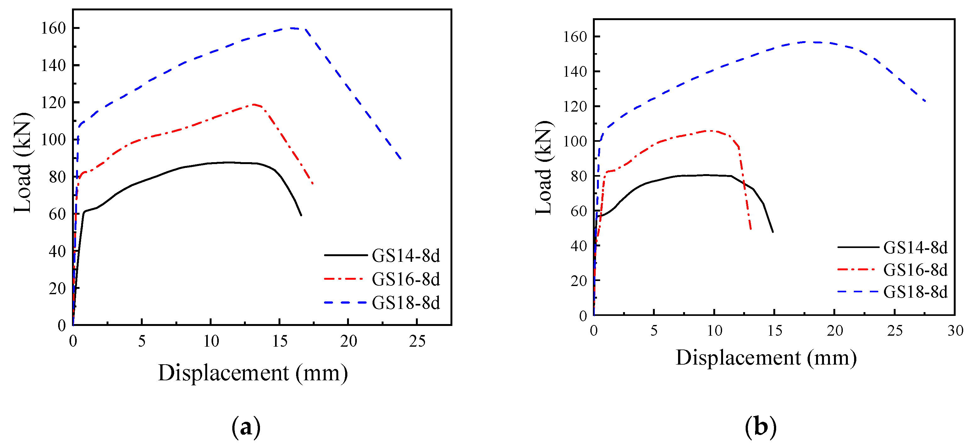
3.3. Parameter Analysis of Grouting Sleeve Connection Performance

3.3.1. Anchorage Length of Reinforcement

Without considering grouting defects, the load–displacement curves of the grouting sleeve specimens with different anchorage lengths (4d, 5d, 8d) and the same reinforcement diameter of 16 mm are shown in Figure 12. The failure mode of specimen GS16-8d is the tensile failure of the reinforcement, and the failure mode of specimens GS16-5d and GS16-4d is pull-out failure of the reinforcement. When the anchorage length of the reinforcement is 5d, it can meet the strength requirements of grouting sleeve connection performance. With the increase in the anchorage length of the reinforcement, the ultimate bearing capacity of the specimen increases. The ultimate loads of specimens GS16-4d, GS16-5d, and GS16-8d are 79.29 kN, 118.22 kN, and 118.81 kN, respectively. That is, the ultimate bearing capacity decreases by 33.26% when the anchorage length of the reinforcement decreases from 8d to 4d. This shows that the anchorage length of the reinforcement has a significant impact on the performance of the grouting sleeve connection.
When the grout defects are considered, the load–displacement curves of grouting sleeve specimens with 5% and 10% random defects are shown in Figure 13. When the random defects account for 5%, the failure mode of each specimen is consistent with that without defects, and the ultimate loads of the three specimens are 72.82 kN, 106.51 kN, and 118.23 kN, respectively. When the random defects account for 10%, the failure mode of each specimen is the tensile failure of the steel bars, and the ultimate loads of the three specimens are 65.98 kN, 99.51 kN, and 106.02 kN, respectively. In fact, defects are distributed in various ways, and the above simulation is only one of them. However, the simulation results still show that with the increase in the content of random defects, the bonding force between the grouting material and reinforcement decreases, and grouting defects have a significant impact on the bonding performance and failure mode of the grouting sleeves.

3.3.2. Diameter of Reinforcement

Based on the above analysis, the performance of grouting sleeves without defects and with 10% random defects are compared here. The load–displacement curves of specimens GS14-8d, GS16-8d, and GS18-8d are shown in Figure 14. When, with no defects, the three specimens all fail due to the reinforcement tensile failure, the bonding property between the grouting material and the reinforcement is good, and the ultimate loads are 87.59 kN, 118.81 kN, and 160.03 kN, respectively. It shows that with the increase in the diameter of the reinforcement, the ultimate bearing capacity of the specimen increases. When the diameter of the reinforcement increases from 14 mm to 18 mm, the ultimate bearing capacity increases by 45.27%. When the defect content increases to 10%, the bonding force between the grouting material and reinforcement decreases rapidly. The failure mode of the three grouting sleeve specimens is reinforcement pullout failure, and the ultimate load decreases to 80.41 kN, 106.02 kN, and 156.95 kN, respectively. Therefore, the defect of the grouting material has a significant impact on the connection performance and failure mode of the grouting sleeves.

4. Study on the Anti-Explosion Response of the Fabricated Shear Wall with Grouting Defects

In view of the realization of the above simulation, this section introduces the grouting material defects into the study of components. Considering that the gas explosion hazard is prominent at present, which is a great challenge in the performance of the connections of the shear wall, the anti-explosion performance of the prefabricated concrete shear wall with grout defects under explosive load is analyzed through the numerical simulation in this section, and the feasibility of the application of the above simulation technology in component performance is verified.

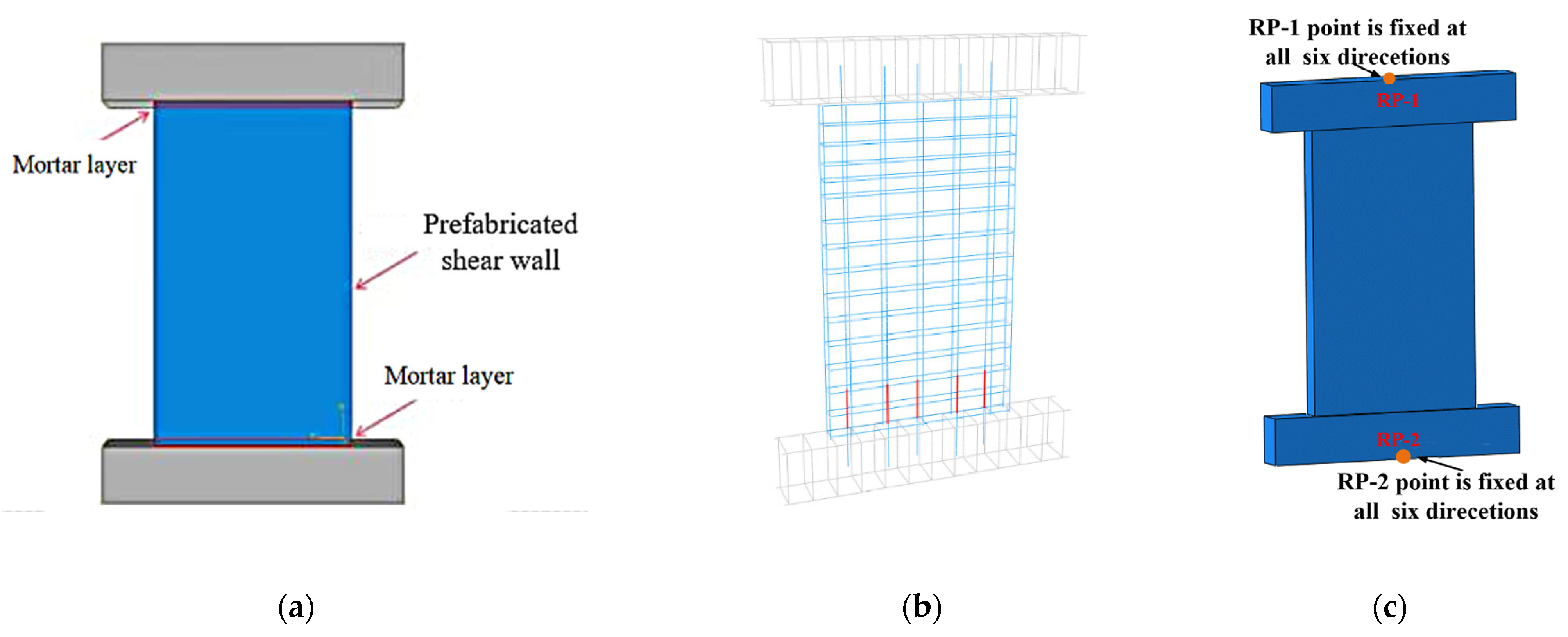
4.1. Finite Element Model and Relevant Parameters

The shear wall components are composed of reinforcement, the grouting layer, the grouting sleeve, the ground beam, and the bent cap, as shown in Figure 15. The size of the shear wall is 2750 mm × 1650 mm × 200 mm, where the concrete grade is C30, the thickness of the concrete cover is 25 mm, the reinforcement is HRB400, the diameters of vertical reinforcement and horizontal reinforcements are 16 mm and 12 mm, respectively, and the spacing between the reinforcements is 200 mm. The height of the beam is 400 mm, where the diameter of the stirrups is 10 mm, the spacing between the stirrups is 100 mm, and the diameter of the longitudinal reinforcement is 16 mm. The improved CDP model [32] proposed by the authors’ research group, which can take into account the correlation of the damage factor rate, is adopted for the concrete constitutive model in this study. The Johnson Cook model is adopted as the dynamic constitutive model for the reinforcement and sleeve. The simulated uniaxial tensile data of the grouting sleeve with defects are imported into the JC model, and the failure displacement is set to simulate the pullout failure of the sleeve. In order to ensure calculation accuracy and analysis efficiency, the solid element C3D8R is used for the concrete, the two-node T3D2 truss element is used for both the longitudinal reinforcement and stirrups, and the T3D2 truss element is used for the grouting sleeve, which is equivalent to a full-length slender homogeneous body. The size of the mapping grid of the shear wall is 25 mm. Considering that there is a new and old concrete contact surface at the bottom of the prefabricated shear wall component, the tangential friction coefficient is set as 0.6 and the normal friction coefficient is set as “hard contact” at the upper and lower mortar layer contact surfaces of the prefabricated shear wall. An embedding constraint is used between the reinforcement and concrete, without considering the influence of bond slip. Reference points are set at the upper and lower ends of the model for section coupling, and the two points are restrained as fixed ends, as shown in Figure 15c.
The CONWEP air explosion module built in ABAQUS is used to simulate the explosion load. Assuming initiation point X, the distance from the explosion center to the bottom of the shear wall is b, 687.5 mm, which is located at one-quarter of the height of the prefabricated wall, and the distance from the explosion center to the blasting surface of the shear wall is h, as shown in Figure 16. In order to study the anti-explosion performance of the prefabricated shear walls, two parameters, the TNT equivalent and the distance to the blasting surface, are taken to compare and analyze the dynamic response of the prefabricated shear walls under different explosion loads. Among them, the TNT equivalent values are taken as 3 kg, 5 kg, 7 kg, 9 kg, and 10 kg, respectively, and the distances to the blast surfaces are taken as 1/8, 3/16, 3/8, 1/2, and 3/4 times the heights of the prefabricated shear walls, respectively.

4.2. Parameter Influence Analysis

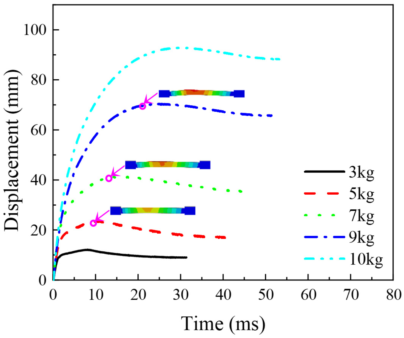
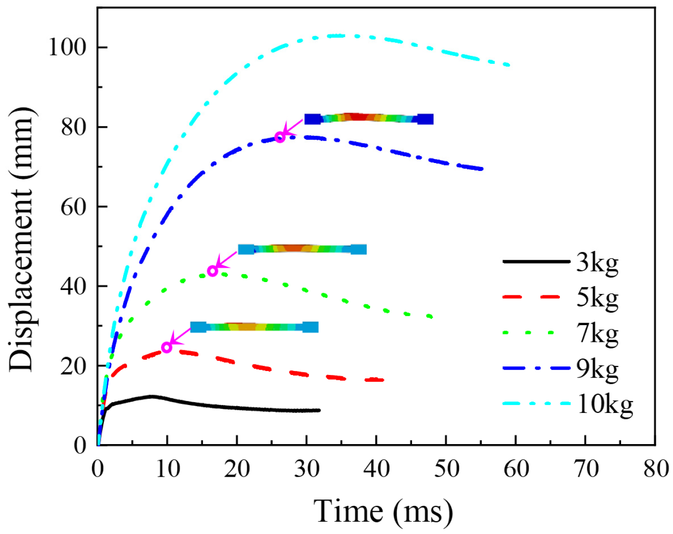
4.2.1. Impact of the TNT Equivalent

In this section, the distance from the initiation point to the blasting surface of the shear wall is taken as one-eighth of the height of the prefabricated shear wall, and the dynamic responses of the assembled shear wall under five different TNT equivalent explosions of 3 kg, 5 kg, 7 kg, 9 kg, and 10 kg are compared and analyzed.
Without considering the defects of grouting materials, Figure 17 shows the failure characteristics on the front and back blasting surfaces of three typical shear walls with the TNT equivalent values of 3 kg, 5 kg, and 9 kg, respectively. When the explosive equivalent is 3 kg, the concrete near the explosion center of the blasting surface is slightly damaged. When the equivalent is increased to 5 kg, the concrete at the restraint end of the back blasting surface of the shear wall is crushed. When continuing to increase to 9 kg, the concrete at the front blasting surface is damaged in a large area, the concrete at the back blasting surface is cracked, the reinforcement is bent, and the restraint end of the shear wall is severely damaged. It can be seen that, with the increase in the explosive equivalent, the damaged area of concrete gradually increases, and the middle of the back blasting surface of the wall near the explosion center has a large displacement. The displacement–time curves of the assembled shear wall under different explosive loads are shown in Figure 18. With the increase in the explosive equivalent, the displacement of the fabricated shear wall increases continuously, with maximum displacements of 12.14 mm, 23.55 mm, 41.31 mm, 70.41 mm, and 92.85 mm, respectively. That is, when the explosive equivalent increases from 3 kg to 10 kg, the maximum displacement increases by 6.6 times.
When considering the influence of a 10% volume fraction of grouting material defects, the damage distribution characteristics of the front and back blasting surfaces of the shear wall under different explosion loads have little difference from that without defects, but the damaged area of the concrete increases, as shown in Figure 19. The maximum displacement for the shear wall under the explosive equivalent values of 3 kg, 5 kg, 7 kg, 9 kg, and 10 kg increases to 12.21 mm, 23.66 mm, 43.04 mm, 77.51 mm, and 103.02 mm, respectively, as shown in Figure 20. With 10% grouting defects, when the explosive equivalent increases from 3 kg to 10 kg, the maximum displacement increases by 7.4 times.
Besides, with the appearance of grouting defects, the ultimate bearing capacity of the grouting sleeve decreases rapidly. When the explosive equivalent increases, the concrete at the mortar setting layer will fail, and the concrete at the shear wall support on the back blasting surface will be significantly damaged under compression. The equivalent T3D2 truss element simulating sleeve specimen will fail, as shown in Figure 21, and the sleeve at the bottom of the front blasting surface of the shear wall will be damaged by the steel bar pullout.
From the comparison of the peak displacement diagrams for different TNT equivalents without defects and considering defects (Figure 22), it can be seen that with the increase in the explosive equivalent, the difference between the peak displacements increases continuously. When the explosive equivalent increases to 10 kg, the peak displacement of the shear wall considering defects increases by 9.87% compared with that of the shear wall without grouting defects, and the anti-explosion performance of the wall decreases significantly. Thus, the sleeve grouting defect has a significant impact on the connection performance of the fabricated joints, and this defect will directly reduce the external stiffness of the fabricated shear wall.

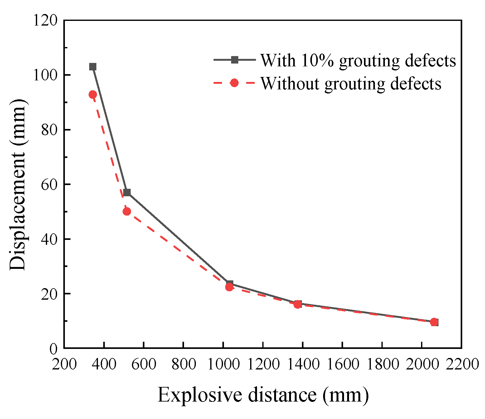
4.2.2. Impact of Explosive Distance

When the TNT equivalent is 10 kg, the dynamic responses of five fabricated shear walls, with distances from the initiation point to the blasting surface of the shear wall 1/8, 3/16, 3/8, 1/2, and 3/4 that of the height of the prefabricated shear wall, are studied. That is, the distances from the initiation point to the blasting surface are 343.75 mm, 515.62 mm, 1031.25 mm, 1375 mm, and 2062.5 mm, respectively. Considering that the damage distributions of the front blasting surface and back blasting surfaces are similar, only the displacement–time curves of the fabricated shear wall corresponding to different distances of the front blasting surface are given here, as shown in Figure 23a. The limit displacement of the fabricated shear wall decreases with the increase in the distance to the blasting surface, and the peak displacements are 92.83 mm, 50.06 mm, 22.36 mm, 16.07 mm, and 9.56 mm, respectively.
Regarding 10% grouting defects, the displacement–time curves of the shear wall are shown in Figure 23b, and the peak displacement increases to 103.02 mm, 57.08 mm, 23.67 mm, 16.44 mm, and 9.70 mm, respectively. When the distance from the initiation point to the blasting surface is relatively close, the ultimate bearing capacity of the grouting sleeve decreases rapidly, the equivalent T3D2 truss unit simulating the sleeve specimen fails, the sleeve at the bottom of the blasting surface of the shear wall is damaged by reinforcement pulling out, and the connection of the shear wall support is severely damaged. Figure 24 shows that the difference between the peak displacements of the wall with and without defects increases with the decrease in the distance from the explosion point. It is verified that the grouting defects have a significant impact on the out-plane stiffness of the prefabricated shear wall. Under the action of the explosion load, the closer to the explosion point, the more obvious the influence of grouting material defects on the wall stiffness.

5. Conclusions and Outlook

In this paper, the construction method of a three-dimensional random defect model for grouting materials developed based on the ABAUQS script is used to simulate and verify the reinforced grouting sleeve specimens with defects and is applied to the research on the anti-explosion performance of the prefabricated shear wall with defects. The following beneficial conclusions are obtained, and future development suggestions are given:
(1) The model of grouting materials with three-dimensional random defects is close to the random requirements of actual production, greatly simplifies the analysis process, improves the calculation efficiency, and provides a reliable and efficient technical method for more accurate prediction of the connection performance of grouting sleeves with grouting defects.
(2) The finite element model of grouting sleeves is constructed by considering the random defects of grouting materials and was compared with the results of the uniaxial tensile test. The load–displacement curves and tensile failure modes of the grouting sleeves with different reinforcement anchorage lengths and diameters are obtained, which proves the accuracy and feasibility of the simulation method.
(3) The random defect simulation method is used to simulate the mechanical properties of the grouting sleeve and is also applied to the performance simulation of the shear wall structure. The anti-explosion performances of the shear wall with defects at different TNT equivalents and explosion distances are simulated, which verifies the feasibility of the numerical simulation method proposed in this paper applied to structural members.
(4) Due to the diversity of defect distribution types, a single defect distribution mode cannot summarize the mechanical performances of grouting sleeves and shear wall components. In the future, the performance study of grouting sleeves and shear wall components with grouting defects of different shapes, sizes, and distribution modes, should be carried out based on this method.

Author Contributions

Conceptualization, B.T., H.S., Z.X., Y.Z. and L.C.; methodology, B.T., L.C. and Y.Z.; software, J.W. and Y.Z.; validation, H.S. and Z.X.; formal analysis, B.T. and J.W.; investigation, H.S. and Z.X.; resources, B.T. and L.C.; data curation, J.W. and Y.Z.; writing—original draft preparation, B.T., H.S. and Z.X.; writing—review and editing, B.T., H.S. and Z.X.; visualization, Z.X. and J.W.; supervision, B.T. and L.C.; project administration, Z.X. funding acquisition, H.S. and Z.X.. All authors have read and agreed to the published version of the manuscript.

Funding

This research was funded by the National Natural Science Foundation of China, grant numbers 52208188 and 52108236; the Natural Science Foundation of Jiangsu Province, grant number BK20200986; the Natural Science Research Foundations of the Higher Education Institutions of Jiangsu Province, grant number 19KJB560020; the Youth Science and Technology Talent Support Project of Jiangsu Association for Science and Technology, grant number 2021-077; the Research Project of Suzhou Construction System, grant number 2021; the National Natural Science Foundation of Suzhou University of Science and Technology, grant number XKQ2019001.

Acknowledgments

The authors acknowledge the support from the National Natural Science Foundation of China, Jiangsu Provincial Department of Science and Technology, Jiangsu Education Department, Jiangsu Association for Science and Technology, Suzhou Housing and Urban Rural Development Bureau and Suzhou University of Science and Technology.

Conflicts of Interest

The authors declare no conflict of interest.

References

  1. Ghayeb, H.H.; Razak, H.A.; Sulong, N.R. Performance of dowel beam-to-column connections for precast concrete systems under seismic loads: A review. Constr. Build. Mater. 2020, 237, 117582. [Google Scholar] [CrossRef]
  2. O’Hegarty, R.; Kinnane, O. Review of precast concrete sandwich panels and their innovations. Constr. Build. Mater. 2020, 233, 117145. [Google Scholar] [CrossRef]
  3. Tawil, H.; Tan, C.G.; Sulong, N.H.R.; Nazri, F.M.; Sherif, M.M.; El-Shafie, A. Mechanical and thermal properties of composite precast concrete sandwich panels: A Review. Buildings 2022, 12, 1429. [Google Scholar] [CrossRef]
  4. Halding, P.S. Reduction of the carbon footprint of precast columns by combining normal and light aggregate concrete. Buildings 2022, 12, 215. [Google Scholar] [CrossRef]
  5. El-Abidi, K.M.A.; Ofori, G.; Zakaria, S.A.S.; Aziz, A.R.A. Using prefabricated building to address housing needs in Libya: A study based on local expert perspectives. Arab. J. Sci. Eng. 2019, 44, 8289–8304. [Google Scholar] [CrossRef]
  6. Lei, M.Z.; Cui, T. A scientometric analysis and visualization of global LEED research. Buildings 2022, 12, 1099. [Google Scholar] [CrossRef]
  7. Oettel, V.; Empelmann, M. Structural behavior of profiled dry joints between precast ultra-high performance fiber reinforced concrete elements. Struct. Concrete. 2019, 20, 446–454. [Google Scholar] [CrossRef] [Green Version]
  8. Zhu, Z.F.; Guo, Z.X. Seismic performance of the spatial model of precast concrete shear wall structure using grouted lap splice connection and cast-in-situ concrete. Struct. Concrete. 2019, 20, 1316–1327. [Google Scholar]
  9. Guo, J.C.; Zhou, Z.X.; Zou, Y.; Zhang, Z.Y.; Jiang, J.L. Finite element analysis of precast concrete deck-steel beam-connection concrete (PCSC) connectors using ultra-high performance concrete (UHPC) for the composite beam. Buildings 2022, 12, 1402. [Google Scholar] [CrossRef]
  10. Chen, W.H.; Xie, Y.J.; Guo, X.H.; Li, D. Experimental investigation of seismic performance of a hybrid beam-column connection in a precast concrete frame. Buildings 2022, 12, 801. [Google Scholar] [CrossRef]
  11. De la Varga, I.; Haber, Z.B.; Graybeal, B. Enhancing shrinkage properties and bond performance of prefabricated bridge deck connection grouts: Material and component testing. J. Mater. Civil. Eng. 2018, 30, 04018053. [Google Scholar] [CrossRef]
  12. Wakisaka, T.; Furuya, N.; Inoue, Y.; Shiokawa, T. Automated construction system for high-rise reinforced concrete buildings. Automat. Constr. 2000, 9, 229–250. [Google Scholar] [CrossRef]
  13. Guo, F.; Li, J.H.; He, S.C.; Zhou, C.H. Experimental study on the effect of grouting defects on mechanical properties of the rebar connected by full-grouted sleeves. Adv. Civ. Eng. 2022, 2022, 5036505. [Google Scholar] [CrossRef]
  14. Ji, Y.B.; Zhao, Z.H.; Yao, F.Y.; Li, H.X.; Li, Y.Y.; Du, X.Y. Factors influencing sleeve grouting quality for prefabricated building: An interpretive structural modeling approach. Adv. Civ. Eng. 2021, 2021, 5598424. [Google Scholar] [CrossRef]
  15. Yao, F.Y.; Ji, Y.B.; Tong, W.J.; Li, H.X.; Liu, G.W. Sensing technology based quality control and warning systems for sleeve grouting of prefabricated buildings. Automat. Constr. 2021, 123, 103537. [Google Scholar] [CrossRef]
  16. Li, D.S.; Liu, H. Detection of sleeve grouting connection defects in fabricated structural joints based on ultrasonic guided waves. Smart. Mater. Struct. 2019, 28, 085033. [Google Scholar] [CrossRef]
  17. Liu, H.; Qi, Y.; Chen, Z.J.; Tong, H.W.; Liu, C.; Zhuang, M.W. Ultrasonic inspection of grouted splice sleeves in precast concrete structures using elastic reverse time migration method. Mech. Syst. Signal. Pract. 2020, 148, 107152. [Google Scholar] [CrossRef]
  18. Xu, B.; Fan, X.L.; Wang, H.D.; Zhou, S.J.; Wang, C.; Chen, H.B.; Ge, H.B. Experimental study on grout defects detection for grouted splice sleeve connectors using stress wave measurement. Constr. Build. Mater. 2021, 274, 121755. [Google Scholar] [CrossRef]
  19. Xu, F.; Wang, K.; Wang, S.G.; Li, W.W.; Liu, W.Q.; Du, D.S. Experimental bond behavior of deformed rebars in half-grouted sleeve connections with insufficient grouting defect. Constr. Build. Mater. 2018, 185, 264–274. [Google Scholar] [CrossRef]
  20. Zheng, G.Y.; Kuang, Z.P.; Xiao, J.Z.; Pan, Z.F. Mechanical performance for defective and repaired grouted sleeve connections under uniaxial and cyclic loadings. Constr. Build. Mater. 2020, 233, 117233. [Google Scholar] [CrossRef]
  21. Guo, T.; Yang, J.; Wang, W.; Li, C. Experimental investigation on connection performance of fully-grouted sleeve connectors with various grouting defects. Constr. Build. Mater. 2022, 327, 126981. [Google Scholar] [CrossRef]
  22. Xiao, S.; Wang, Z.L.; Li, X.M.; Harries, K.A.; Xu, Q.F.; Gao, R.D. Study of effects of sleeve grouting defects on the seismic performance of precast concrete shear walls. Eng. Struct. 2021, 236, 111833. [Google Scholar] [CrossRef]
  23. Guo, H.; Zhang, J.X.; Wang, C.W. Experimental study on influence of connection defects on joint strength of half-grouted sleeve splicing of rebar. Adv. Civ. Eng. 2020, 2020, 5389861. [Google Scholar] [CrossRef]
  24. Li, X.M.; Xiao, S.; Gao, R.D.; Harries, K.A.; Wang, Z.L.; Xu, Q.F. Effects of grout sleeve defects and their repair on the seismic performance of precast concrete frame structures. Eng. Struct. 2021, 242, 112619. [Google Scholar] [CrossRef]
  25. Li, F.R.; Abruzzese, D.; Milani, G.; Li, S.C. Influence of internal defects of semi grouted sleeve connections on the seismic performance of precast monolithic concrete columns. J. Build. Eng. 2022, 49, 104009. [Google Scholar] [CrossRef]
  26. Gong, C.J.; Wang, Y.Y.; Peng, Y.C.; Ding, W.Q.; Lei, M.F.; Da, Z.H.; Shi, C.H. Three-dimensional coupled hydromechanical analysis of localized joint leakage in segmental tunnel linings. Tunn. Undergr. Space Technol. 2022, 130, 104726. [Google Scholar] [CrossRef]
  27. Yao, F.; Abulikemu, A. Effect of impact source on detection quality in impact echo testing of sleeve grouting. Mater. Test. 2020, 62, 927–936. [Google Scholar] [CrossRef]
  28. Qiao, D.H.; Xu, Y.Q.; Zhang, X.; Pang, J.B.; Liu, K.; Wang, S.J. Seismic behaviour and size effect of column base joints with inverted exposed grouted sleeves. J. Build. Eng. 2022, 51, 104333. [Google Scholar] [CrossRef]
  29. Yan, H.; Song, B.; Xu, D.S.; Zhang, G.D. Seismic performance of assembled shear wall with defective sleeve connection. CMES-Comp. Model. Eng. 2022, 131, 199–217. [Google Scholar] [CrossRef]
  30. Kahama, E.K.; Fuzhe, X.; Anglaaere, D.L.M. Numerical study on the influence of defects in grouting on the mechanical properties of a full grouted sleeve connector. J. Adhesion. 2021, 98, 2550–2581. [Google Scholar] [CrossRef]
  31. Duan, W.F.; Zhou, J.Y.; Liu, W.Y.; Peng, L.J. Explicit finite element analysis of connection performance of grouted sleeve. J. Jilin Jianzhu Univ. 2021, 38, 1–8. (In Chinese) [Google Scholar]
  32. Zhang, Y.J.; Chen, L.; Xie, P.C.; Tang, B.J.; Shen, H.J. Rate correlation of the ABAQUS damage parameter in the Concrete Damage Plasticity Model and its realization method. Explos. Shock. Waves 2022, 42, 103103. (In Chinese) [Google Scholar]
Figure 1. Model building flowchart.
Buildings 12 01859 g001
Figure 2. Diagram of random spheres.
Buildings 12 01859 g002
Figure 3. Defect model. (a) Preliminary defect model. (b) Defect model after Boolean operation.
Buildings 12 01859 g003
Figure 4. Schematic diagram of specimen.
Buildings 12 01859 g004
Figure 5. Diagrams of grouting defects models. (a) 5% defects model. (b) 10% defects model.
Buildings 12 01859 g005
Figure 6. Diagrams of model meshes. (a) Sleeve. (b) Reinforcement. (c) Grouting material. (d) Specimen GS16-8d.
Buildings 12 01859 g006
Figure 7. Diagrams of grouting defect meshes. (a) 5% grouting defects. (b) 10% grouting defects.
Buildings 12 01859 g007
Figure 8. Grouting defect grid schematics. (a) Without defects. (b) With 25% defects at the end.
Buildings 12 01859 g008
Figure 9. Failure modes of the grouting sleeves without and with defects. (a) Without defects. (b) With 25% defects at the end.
Buildings 12 01859 g009
Figure 10. Comparison of load–displacement curves of grouting sleeves with and without defects. (a) Without defects. (b) With 25% defects at the end.
Buildings 12 01859 g010
Figure 11. Pullout failure process of reinforcement. (a) Stripping of reinforcement and grouting material interface. (b)Reinforcement pullout. (c) Reinforcement completely pullout.
Buildings 12 01859 g011aBuildings 12 01859 g011b
Figure 12. Load–displacement of specimens with different anchorage lengths and without grouting defects.
Buildings 12 01859 g012
Figure 13. Load–displacement curves of the specimens with different anchorage lengths and grouting defects. (a) With 5% random defects. (b) With 10% random defects.
Buildings 12 01859 g013
Figure 14. Load–displacement curves of the specimens with different reinforcement diameters. (a) Without random defects. (b) With 10% random defects.
Buildings 12 01859 g014
Figure 15. Finite element model diagram. (a) Shear wall. (b) Sleeves and reinforcement. (c) restraint fixed end.
Buildings 12 01859 g015
Figure 16. Explosive loading mode.
Buildings 12 01859 g016
Figure 17. Failure characteristics of the prefabricated shear walls without defects under different explosive equivalent values. (a) 3 kg, front blasting surface. (b) 3 kg, back blasting surface. (c) 5 kg, front blasting surface. (d) 5 kg, back blasting surface. (e) 9 kg, front blasting surface. (f) 9 kg, back blasting surface.
Buildings 12 01859 g017
Figure 18. Displacement–time curves of the prefabricated shear wall without defects under different explosive equivalent values.
Buildings 12 01859 g018
Figure 19. Failure characteristics of the prefabricated shear walls with 10% grouting defects under different explosive equivalent values. (a) 3 kg, front blasting surface. (b) 3 kg, back blasting surface. (c) 5 kg, front blasting surface. (d) 5 kg, back blasting surface. (e) 9 kg, front blasting surface. (f) 9 kg, back blasting surface.
Buildings 12 01859 g019aBuildings 12 01859 g019b
Figure 20. Displacement–time curves of the prefabricated shear wall with 10% grouting defects under different explosive equivalent values.
Buildings 12 01859 g020
Figure 21. Displacement nephograms of the grouting sleeve and reinforcement under an explosive equivalent of 10 kg. (a) Without grouting defects. (b) With 10% grouting defects.
Buildings 12 01859 g021aBuildings 12 01859 g021b
Figure 22. Peak displacement of the shear wall under different TNT equivalents.
Buildings 12 01859 g022
Figure 23. Displacement–time curves of the fabricated shear wall with different explosive distances. (a) Without grouting defects. (b) With 10% grouting defects.
Buildings 12 01859 g023
Figure 24. Peak displacements of the shear wall with different explosive distances.
Buildings 12 01859 g024
Table 1. Specimen dimensions.
Specimensd
(mm)
h
/mm
l01
/mm
l1
/mm
L1
/mm
l2
/mm
L2
/mm
Ls
/mm
Lgs
/mm
GS16-4d161001001564204d328330658
GS16-5d161001001564205d344330658
GS16-8d161001001564208d392330658
GS14-8d141001001403968d368300612
GS18-8d181001001724448d416360704
Table 2. CDP model parameters.
Dilation AngleFlow Potential OffsetRatio of Biaxial to Uniaxial Compressive StrengthInvariant Stress RatioViscosity
30°0.11.160.66670.0005
Table 3. Material parameters.
MaterialDiameter
(mm)
Yield Strength
(MPa)
Yield StrainTensile Strength
(MPa)
Ultimate StrainElastic Modulus
(GPa)
Density
(kg·m−3)
Poisson’s Ratio
Reinforcement14425.080.00226636.620.176120078000.3
16461.560.00231622.850.177320078000.3
18425.170.00213620.750.165920078000.3
Sleeve393550.001726000.12120625000.2
Publisher’s Note: MDPI stays neutral with regard to jurisdictional claims in published maps and institutional affiliations.

