Article

Double-Diffusive Mixed Convection and Radionuclides Removals from the Tail Gas Treatment Unit in Nuclear Medicine Building: Multiple Sifting Structures and Porous Medium

1
The First Construction Engineering Limited Company of China Construction Third Engineering Bureau, Wuhan 430070, China
2
School of Power and Mechanical Engineering, Wuhan University, Wuhan 430072, China
*
Authors to whom correspondence should be addressed.
Buildings 2022, 12(11), 1842; https://doi.org/10.3390/buildings12111842
Submission received: 4 October 2022 / Revised: 22 October 2022 / Accepted: 26 October 2022 / Published: 1 November 2022
(This article belongs to the Special Issue Energy Efficient, Low Carbon and Energy Flexible Buildings)

Abstract

:
This paper investigates the effect of porous-media arrangement, hot-plate arrangement, heat flux, and inlet flow on the mixed convection heat transfer, and uniformity of temperature and concentration in an open enclosure. This model is considered for use as an adsorption treatment unit for radioactive waste gas in a nuclear medicine building. The radioactive waste gas flows through the cavity from bottom to top. The two-dimensional governing equations have been solved using the finite volume method. The Prandtl number and aspect ratio of the cavity are fixed at 0.71 and 1, respectively. The problem has been governed by five parameters: −10 ≤ Br ≤ 10, 10−6Da ≤ 102, 0.1 ≤ Kc ≤ 10, 10−2Ri ≤ 10, and 0.1 ≤ Kr ≤ 10, and the layouts of the porous layer and hot plates. The simulation results indicate that the Type C (polymeric porous media) has excellent heat transfer characteristics with a 10% increase in the Nusselt number (Nu). The contours of streamlines, isotherms and heatlines indicate that, with the increase of Richardson number (Ri), the trend of Nu varies for different arrangements of hot plates. It is interesting to note that the convective heat transfer of Type F (surrounded arrangement) was found to have the lowest Nu number for the same Ri number. The convective heat transfer is more pronounced for Type E (symmetrical arrangement). The Nu number of Type E (symmetrical arrangement) is about 110% higher than that of Type F (surrounded arrangement) and it is about 35% higher than that of Type D (centralized arrangement). This type also has a more uniform temperature distribution, as indicated by the temperature variance. The findings of this study can guide preheating system optimization.

1. Introduction

With the rapid development of the nuclear industry, the number of reactors in the world is increasing steadily [1,2,3,4,5,6]. However, the development of the nuclear industry and the application of nuclear medicine contribute to an increased emission of radioactive gaseous waste [3,5,6,7,8]. Discharge of untreated radioactive gaseous waste can adversely affect the environment as well as human health; therefore, purification treatment must be carried out to limit radiation exposure from radioactive gaseous waste and avoid radionuclide contamination in the surrounding environment [9].
In recent years, filtration and adsorption methods are becoming popular in the field of radioactive gaseous waste treatment. The adsorption capacity of different adsorbents has been studied to explore an efficient and economical material [10,11]. Moreover, it was pointed out by Underhill [12] that for a given adsorbent, the concentration gradient of the radiant is also a primary factor affecting the adsorption efficiency. The physical interpretation of the mixed convection phenomena in an adsorption unit can be understood as the interaction between the forced convection originating from inlet fluid flow and the free convection originating from the density difference between the hot and cold fluids.
Mixed convection heat transfer in a closed cavity has received considerable attention in recent decades in both academic and industrial fields [12,13,14,15,16,17,18,19,20,21,22,23,24,25]. Ali et al. [13] studied the MHD mixed convection from a rotating circular solid cylinder in a trapezoidal enclosure. It was found that raising the Hartmann number, thermal conductivity ratio, and Darcy number causes the average Nusselt number to grow, whereas increasing the Richardson number causes it to fall. The mixed convection heat transfer in a two-dimensional trapezoidal lid-driven enclosure filled with nanofluids heated from below was quantitatively examined by Kareem et al. [14]. A higher Nusselt number was found for smaller inclination angles and aiding flow. The impact of heaters with different sizes and locations on heat transfer in an inclined square cavity has been studied by Sivasankaran et.al. [15]. They found that the highest heat transfer happened when the heater is located in the middle of the cavity at a cavity inclination angle of γ = 30° in the buoyancy convection-dominated regime. The effect of wall proximity of obstacles, gap space, Reynolds number, and Richardson number on the heat transfer was numerically investigated by Laidoudi [20]. It was observed that gap space has a different effect under aiding thermal buoyancy on the first compared to the second cylinder in fluid characteristics as well as heat transfer effect. A numerical study of mixed convection in a lid-driven partially layered porous enclosure was addressed by Ismael [25]. He observed that the competition between the buoyancy ratio, wall speed, and Lewis number has a considerable influence on heat and mass transfer.
The insistent demands of convective heat transfer control inside enclosures have led to a great deal of study of natural convection in cavities under different thermal boundary conditions and working fluids [26,27,28,29,30,31,32,33,34,35,36,37,38]. In a solar distiller, Ghachem et al. [26] studied double-diffusive natural convection. The interaction of heat energy and the diffusion of chemical species results in an interesting flow pattern. They found that the buoyancy ratio has a great impact on the distributions of isotherms, iso-concentrations, and the structure of the flow. Al-Hassan [35] studied the heat and mass exchange in a composite open cavity connected to a horizontal channel. Three parameters, Reynolds number, Richardson number, and the thickness of the porous layer, were investigated to show their impact on the convective heat transfer efficiency. Double–diffusive natural convection in a partially layered square cavity was later studied by taking more parameters into consideration, e.g., Lewis number, Rayleigh number, Darcy number, geometry, and position of the conductive solid body. The simulation results indicated that the heat transfer is highly affected by the location of the conductive solid body and the Nusselt and Sherwood numbers have contradictory behavior with the location of the solid body [36]. Alsabery et.al [37] investigated the natural convection in a nanofluid-filled wavy-walled porous cavity containing an inner solid cylinder. It was found that the heat transfer varies with the number of undulations. Ben-Nakhi [38,39] studied the impact of the length and inclination of a thin fin in a square enclosure on heat transfer. They observed that the local and average Nusselt numbers change with different parametric conditions and thin-fin inclination angle and length. Chamkha [40,41] studied double-diffusive convection in a porous enclosure with different temperature and concentration gradients. They also studied the influence of inclination effects of the magnetic field direction on the three-dimensional flow structure and heat and mass transfer [27,30,33,34,42,43].
From the above literature review, we can conclude that mixed convection heat transfer varies with heat source geometry, location, and the characteristics of the porous layer, etc. Therefore, for a typical radioactive gaseous waste treatment system, it is important to discuss the influence of the porous layer layout, heat source, and other working conditions on the heat and mass transfer process for adsorption optimization. Moreover, the uniformity of the temperature and mass concentration of the radioactive gaseous waste, which highly affects the adsorption efficiency [6,44], was not considered in previous studies.
In the present study, the preheating unit is simplified to a two-dimensional rectangular cavity and an adsorption bed was considered as a porous media. A detailed investigation of the two-dimensional heat and mass transfer processes of mixed convective flow in the open enclosure considering different hot plate arrangements, heat flux, and inlet gaseous-waste velocity is carried out. The impact of the properties and layout of the enclosure on temperature and mass diffusion was initially determined. A series of dimensionless numbers and variance values were used to evaluate the heat and mass transfer efficiency and distribution uniformity of the working fluid in the system. This study will help reveal the constituent complex heat and mass transfer processes inside preheating system and, hopefully, provide a direction for preheating system optimization.

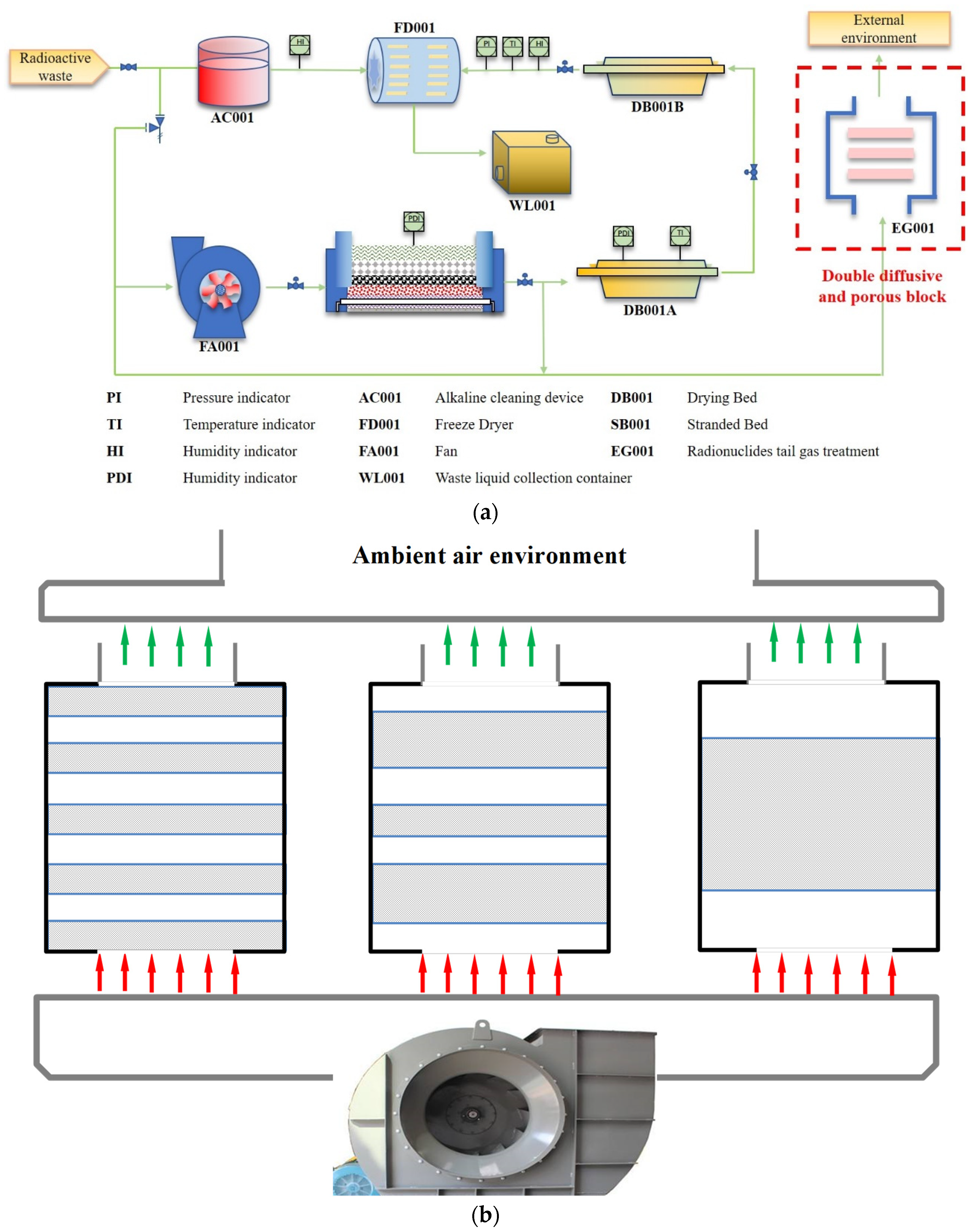
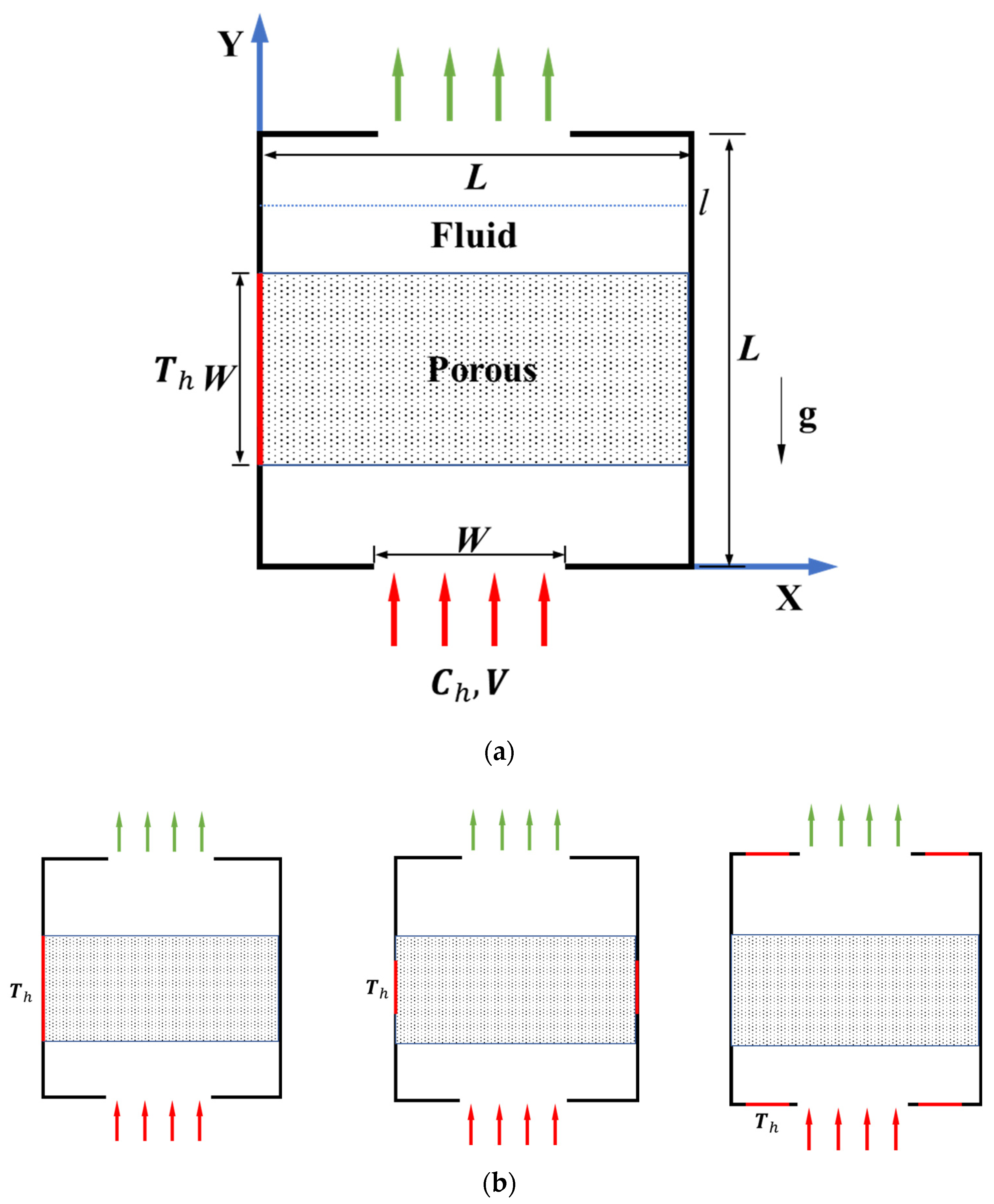
2. Problem Formulation and Mathematical Modeling

Based on [45], the preheating unit is simplified as a cavity with hot plates installed on the inner walls. The waste radioactive gas flows through the cavity vertically. The inlet flow is considered a laminar flow as the Re number is smaller than 1000. Figure 1 shows the process flow schematically. We can then model the process as simplified laminar mixed convection heat transfer in a radionuclide tail gas treatment unit, both of height and width of l. The volume fraction ξ of the total porous fins is kept constant, and the length and width of the porous fins are lfin and wfin, respectively. The left vertical sidewall is subjected to a high-temperature th in order to ensure that water vapor does not condense and to promote the flow and transportation in the treatment unit; whereas the other sidewalls are adiabatic. In addition, there is a supply air flow with a velocity of v0 at the bottom inlet. In this paper, incompressible and laminar flow hypotheses were used. Furthermore, it is assumed that the working fluid has a constant Prandtl number of 0.71 and is a Newtonian fluid. Gravitational acceleration occurs parallel to the vertical sidewalls. With the exception of density fluctuations in the buoyancy force term, the thermal parameters of the working fluid are considered to remain constant. According to the Boussinesq approximation, the density of the fluid phase is expected to fluctuate linearly with temperature and concentration:
ρ = ρ c [ 1 β t ( t t c ) β c ( c c l ) ]
where ρc is the density at temperature t = tc; and βt is the thermal expansion coefficient. Radiation and the effects of viscous heat dissipation are not taken into account in the present model. Vafai et al. [46] pointed out that the local thermal equilibrium (LTE model) is based on the assumption that the temperatures of the solid phase and the liquid phase in porous media are consistent; when the temperature difference between the solid phase and the liquid phase is very small, the LTE model is established. Marafieet al. [47] further studied the validity of the LTE model considering the inertial effect in the fully-filled porous media channel and pointed out that Darcy number and inertial parameters had little influence on the validity of establishing a local heat balance hypothesis. Mahmoudi et al. [48] pointed out that the LTE model is effective when the filling ratio of the porous media is lower than 0.6. Omar et al. [49,50,51,52,53,54] studied in detail the application of Darcy flow and stated that non-Darcy flow models are employed with greater velocities to study the effects of boundary layers and inertial terms, while low mass flow rate applications are often used using the Darcy flow theory. The research content of this present paper satisfies the Darcy flow hypothesis and LTE model. In the porous media, we apply the Darcy–Forchheimer model, which has been validated by many researchers [45,55,56].
The following formula denotes the total volume fraction ξ of the porous blocks:
ξ = N l f i n w f i n L 2 = N W f i n = 0.6
where N indicates the number of porous fins, and in the current study, the overall volume fraction ξ is set at 0.6.

2.1. Governing Equations

The length, velocity, pressure, temperature, and mass scales are introduced in the current study as L, v0, p, T, and C, respectively. Given the presumptions and characteristic scales mentioned above, the following formula yields a set of dimensionless parameters:
X = x L , Y = y L , U = u u 0 , V = v u 0 , P = ( p + ρ c g y ) ρ c u 0 2 , Δ t = t h t c , Δ c = c h c l
T = t t c Δ t , C = c c l Δ c , Pr = ν α , G r = g β Δ t L 3 ν 2 , R e = v 0 L υ f , L e = α D
K r = k p k f , K c = ρ p D p ρ c D f , B r = β c Δ c β t Δ t , D a = K L 2 , R i = G r Re 2
The governing equations for the fluid region of the mixed convection heat transfer problem examined in this paper are presented as follows [15,40,57]. With the aforementioned dimensionless variables, the governing equations can be transformed into conservative non-dimensional forms. Thus, inside the fluid area:
U X + V Y = 0
U U X + V U Y = P X + 1 Re ( 2 U X 2 + 2 U Y 2 )
U V X + V V Y = P Y + 1 Re ( 2 V X 2 + 2 V Y 2 ) + R i T
U T X + V T Y = 1 Re Pr ( 2 T X 2 + 2 T Y 2 )
U C X + V C Y = 1 L e Re Pr ( 2 C X 2 + 2 C Y 2 )
The total representative element volume-averaging approach is used to deal with the governing equations for mass, momentum, and energy conservations within the porous media, which are described in Refs. [16,17,28,54]. Thus, inside the porous media area:
U X + V Y = 0
1 ε 2 ( U U X + V U Y ) = P X + 1 Re 1 ε ( 2 U X 2 + 2 U Y 2 ) 1 Re D a U C F D a V 2 + U 2 U
1 ε 2 ( U V X + V V Y ) = P Y + 1 Re 1 ε ( 2 V X 2 + 2 V Y 2 ) 1 Re D a V C F D a V 2 + U 2 V + R i T
U T X + V T Y = K r Re Pr ( 2 T X 2 + 2 T Y 2 )
U C X + V C Y = K c L e Re Pr ( 2 C X 2 + 2 C Y 2 )
where α is the thermal diffusivity, β is the volumetric expansion coefficient, ρc is the fluid density, υ is the kinematics viscosity of the fluid, K is the permeability of the porous media, ε is the porosity of the porous media, CF is the inertia coefficient, and Kr and Kc are the ratios of saturated porous media to fluid of the effective thermal conductivity and the mass conductivity, respectively. The Prandtl number of the working fluid in the channel air is set to 0.71. The Darcy number indicates the permeability of porous media. Br represents the ratio of mass buoyancy to thermal buoyancy. The Richardson number represents the proportion of shear flow to buoyant plume. Assuming that heat conduction occurs simultaneously in the working fluid and porous matrix, we may calculate the overall thermal conductivity ratio, Kr, which is the ratio of the fluid’s effective thermal conductivity to that of the saturated porous media.
CF, which presents the mathematical expression of the inertia coefficient [48,58] can be expressed as:
C F = 1.75 150 ε 3

2.2. Boundary Conditions

The following formats display the boundary conditions of the aforementioned normalized governing equations. The unit wall adopts the non-slip boundary condition. Except for the discrete heat source and opening, the unit wall has great thermal insulation, so the thermal insulation condition is adopted.
Left wall:
X = 0 , 0 Y L W 2 L , L + W 2 L Y 1 , U = V = 0 , T X = 0 , T C = 0 X = 0 , L W 2 L Y L + W 2 L , U = V = 0 , T = 1 , T C = 0
Right wall:
X = 1 , 0 Y 1 , U = V = 0 , T X = 0 , T C = 0
Bottom wall:
Y = 0 , 0 X L W 2 L , L + W 2 L X 1 , U = V = 0 , T Y = 0 , C Y = 0 Y = 0 , L W 2 L X L + W 2 L , T Y = 0 , V = 1 , C = 1
Top wall:
Y = 1 , 0 X L W 2 L , L + W 2 L X 1 , U = V = 0 , C Y = 0 Y = 1 , L W 2 L X L + W 2 L , V Y = U X , U Y = 0 , T = 0 ( V < 0 ) o r T Y = 0 ( V 0 )
According to [59,60], the following equations can be used to express the flow and heat transfer that occurs at the interface between the pure fluid and the saturated porous fins:
U p o r o u s = U f l u i d , V p o r o u s = V f l u i d μ p U n | p o r o u s = μ f U n | f l u i d , μ p V n | p o r o u s = μ f V n | f l u i d T p o r o u s = T f l u i d = T i n t e r f a c e , C p o r o u s = C f l u i d = C i n t e r f a c e K r T n | p o r o u s = T n | f l u i d , K c C n | p o r o u s = C n | f l u i d

2.3. Visualization of the Convection and Performance Assessment

For engineering applications, the overall rates of heat and mass transmission are crucial. Sherwood number and Nusselt number are usually used to reveal the changes in heat and mass transfer, respectively. They are defined as follows:
N u = h o t ( χ + ( 1 χ ) K r ) ( T X ) | d Y S h = L W 2 L + W 2 ( χ + ( 1 χ ) K c ) ( C Y ) | Y = 0 d X
The characteristics of the fluid flow, heat transfer and mass transfer are effectively visualized by using streamlines, heatlines, and masslines. The heatline and massline concepts were first introduced by Kimura et al. [60] for effective heat and mass flow visualization. These lines are made up of, in turn, constant lines generated from the first derivatives of the stream function ψ, the heat function Θ, and the mass function Π. The non-dimensional form can be expressed as follows:
Ψ Y = U , Ψ X = V
Θ Y = Re Pr U T ( χ + ( 1 χ ) K r ) T X
Θ X = Re Pr V T ( χ + ( 1 χ ) K r ) T Y Π Y = Re Pr Le U T ( χ + ( 1 χ ) K c ) C X Π X = Re Pr Le V T ( χ + ( 1 χ ) K c ) C Y
where χ = 1 represents the fluid region and χ = 0 represents the porous region. If the coordinate origin is selected as the reference point, the values of the stream function, heat function, and mass function are zero. The boundary conditions of the flow function, heat function, and mass function can be obtained by avoiding integration along the cavity.
Variance is a measure of how discrete a random variable or group of data is when measured by probability theory and statistical variance. Variance in probability theory is used to measure the degree of deviation between a random variable and its mathematical expectation (i.e., its mean). [61]. In this paper, the temperature distribution variance at l1, l2, and l3 (Figure 2a) is used to describe the temperature distribution uniformity in the cavity. The corresponding calculation formula of variance is [62]:
s 2 = 1 n 1 i = 1 n ( x i x ¯ ) 2

3. Numerical Methodology and Code Validation

3.1. Numerical Methodology

The dimensionless governing Equations (3)–(12) are solved by using the FVM (finite volume method) based on a staggered grid system [16,41,60] in the current study. Convection and diffusion terms are solved by the third-order delayed correction QUICK (Quadratic Upwind Interpolation of Convective Kinematics) scheme [63] and second-order central difference techniques, respectively.
The governing differential equations were solved numerically using the SIMPLE (Semi-Implicit Method for Pressure Linked Equations) algorithm. Additionally, by integrating across each control volume, the governing equations are discretized to produce a set of algebraic equations. By combining the TDMA (tri-diagonal matrix algorithm) and SOR (successive over-relaxation) iteration, the resulting algebraic equations are solved line-by-line [64,65]. Until the next convergence requirement is met, the iterative process is repeated.
| Φ i , j n + 1 Φ i , j n | | Φ i , j n + 1 | σ
Variable Φ stands for U, V, T, C, and P, with the assumption that σ = 10−6. Grid positions in the (X, Y) plane are represented by the subscript i and j indices. In this investigation, a further drop in the convergence threshold of 10−6 did not result in any variation. The above-mentioned FORTRAN calculations were performed using an internally created solver [58,62,63,64,65,66].
The following equation shows how total energy and mass balance are additional precision controls inside this system for steady-state mixed convection [61,62].
0 1 ( Re Pr U T ( χ + ( 1 χ ) K r ) T X ) | X = 1 d Y 0 1 ( Re Pr U T ( χ + ( 1 χ ) K r ) T X ) | X = 0 d Y + 0 1 ( Re Pr V T ( χ + ( 1 χ ) K r ) T Y ) | Y = 1 d X 0 1 ( Re Pr V T ( χ + ( 1 χ ) K r ) T Y ) | Y = 0 d X = 0 0 1 ( Re Pr Le U T ( χ + ( 1 χ ) K c ) C X ) | X = 1 d Y 0 1 ( Re Pr Le U T ( χ + ( 1 χ ) K c ) C X ) | X = 0 d Y + 0 1 ( Re Pr Le V T ( χ + ( 1 χ ) K c ) C Y ) | Y = 1 d X 0 1 ( Re Pr Le V T ( χ + ( 1 χ ) K c ) C Y ) | Y = 0 d X = 0
Energy and mass balance in Equations (13)–(22) are satisfied within 10−6.

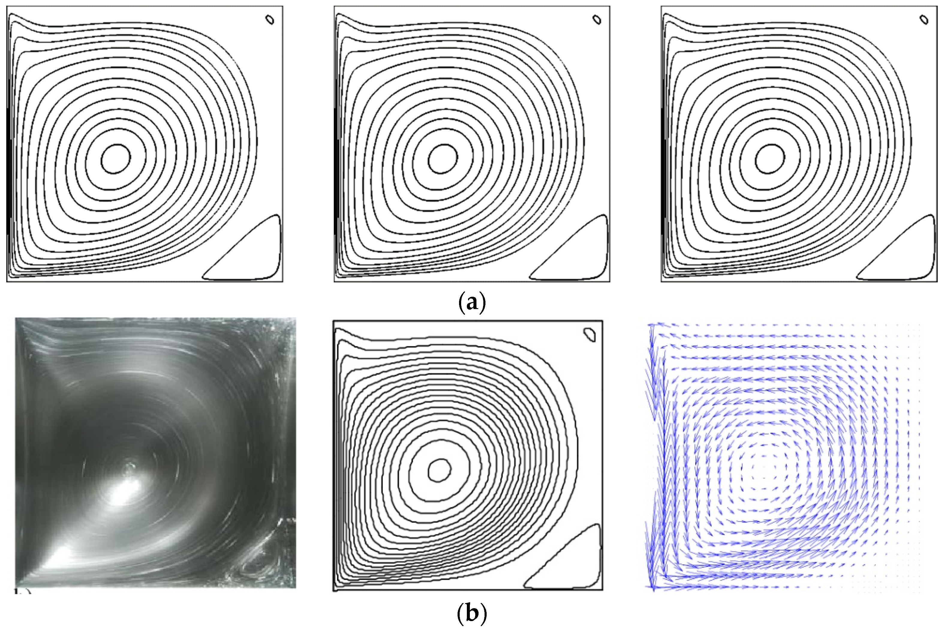
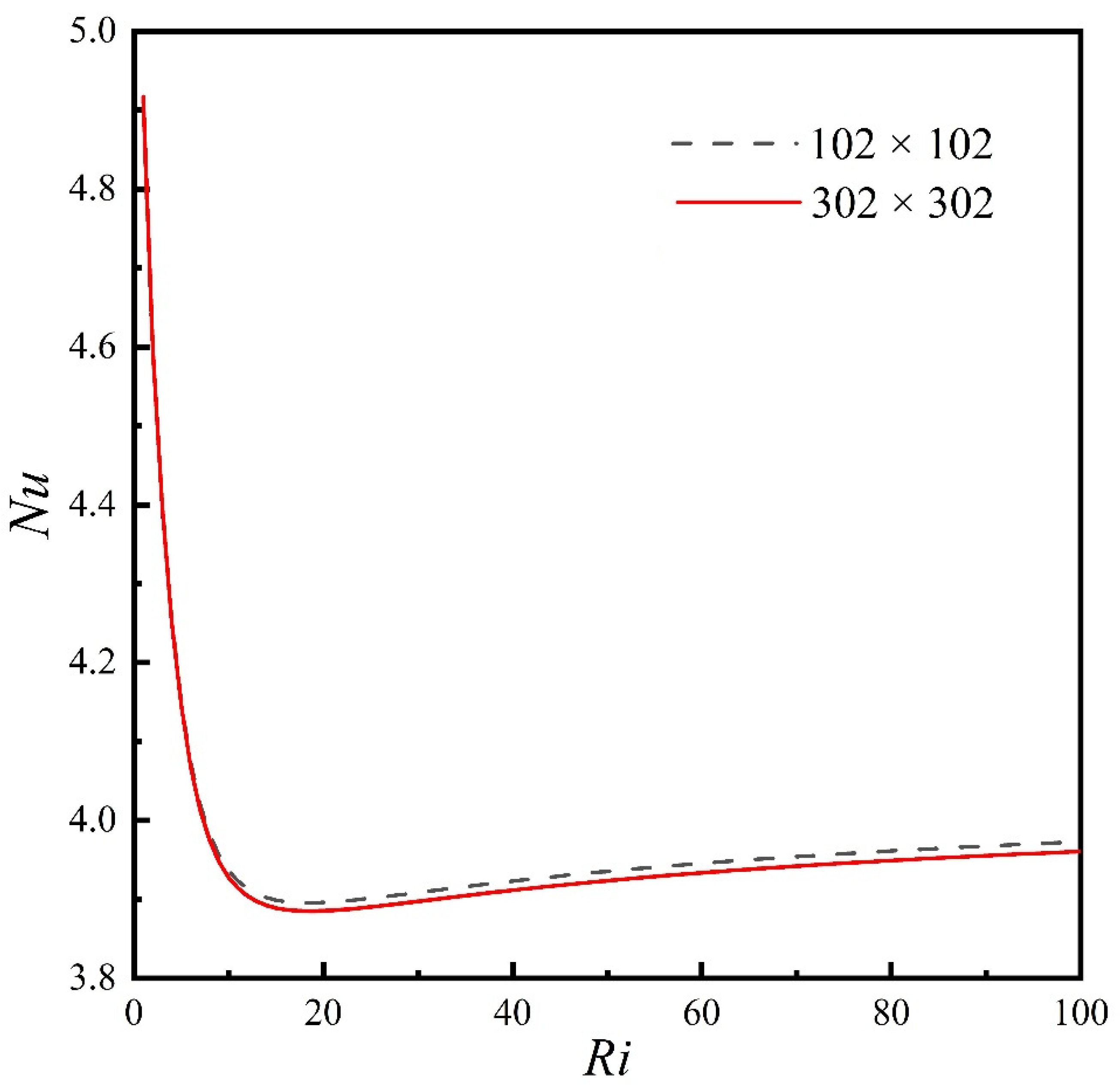
3.2. Establishing the Credibility of the Code and Grid Independence

The validation of the numerical procedure was conducted by comparing the results of the present work with previous studies [67]. As shown in Table 1, the global Nusselt number and Sherwood number found in the present work have been compared with those of Corcione M. Siegmann-Hegerfeld [68] measured the flow in the mixed convection in Figure 3 using a high-speed camera, PIV, and numerical simulation techniques. It is observed that the program employed in this present study can accurately predict the results. The porous media properties are compared with Biswas et al. [69] as shown in Figure 4. Table 1, and Figure 3 and Figure 4 show that the predicted values for various Grashof and Reynolds numbers, match fairly well with other results, with less than a 2% mean error between our results and benchmark results. Therefore, the internally developed programs can be taken as a reliable tool for the investigation of mixed convection in rectangular cavities.
The computed results with Gr = 105, Pr = 0.71, and Ri = 1 to 100, were used to confirm the grid independence. The global Nu number of the hot wall in the cavity with the Ri number is shown in Figure 5. Table 2 displays the effect of the grid number on the Darcy and Richardson numbers. When the grid size exceeded 202 × 202 only slight differences, with less than 1% deviation, were found for the Nu and Ri numbers. In order to fulfill the accuracy of the results and reasonable computing resources, a refined grid system is used in the region of the boundaries and the optimal grid mesh size has been applied in current research.

4. Results and Discussion

All the computations were carried out for a square enclosure of L = 1.0 containing three sifting-matter structures and rectangular porous blocks with ε = 0.8 and volume fraction ξ = 0.6. The treatment unit is filled with humid air characterized by Pr = 0.71 and Le = 0.8. Generally, for the heat and mass transfer in the cavity, the magnitudes of the reference temperature difference and thermal expansion coefficient are 10 K and 10−3 1/K respectively; The magnitudes of the reference concentration difference and mass expansion coefficient are 10−1 kg/m3 and 10−1 kg/kg respectively; The magnitudes of the permeability and mass diffusion coefficients of porous materials are 10−6 m2 and 10−1 kg/m3, respectively. It can be seen that when the magnitude of the cavity width is 10−1 m, the Darcy number, mass diffusion coefficient ratio, and buoyancy ratio can reach O(100), O(10−8), and O(100) respectively. Therefore, numerical results are obtained in the following parameter ranges: −10 ≤ Br ≤10, 10−6Da ≤ 102, 0.1 ≤ Kc ≤ 10, 10−2Ri ≤ 10, and 0.1 ≤ Kr ≤ 10. Six different types (discrete, semi-discrete, and polymeric porous media, and single, symmetric, and surrounding hot plate) are discussed depending on the dimensionless parameters of the treatment unit. The results are presented as streamlines, isotherms, iso-concentrations, and masslines. The overall Nusselt and Sherwood numbers are also presented.
Furthermore, three heat source arrangements of polymeric distribution (Type C) in the cavity are discussed. Numerical results are obtained in the following parameter ranges: 100 ≤ Re ≤1000, 105Gr ≤ 107, and 10−1Ri ≤ 103, while the Darcy number, buoyancy ratio, and porous-fluid thermal conductivity ratio are fixed at 10−3, 1, and 1, respectively. The variances S l 1 2 , S l 2 2 ,   S l 3 2 , were used to measure the uniformity of temperature distribution at different positions in the cavity.

4.1. Discrete, Semi-Discrete, and Polymeric Porous Media

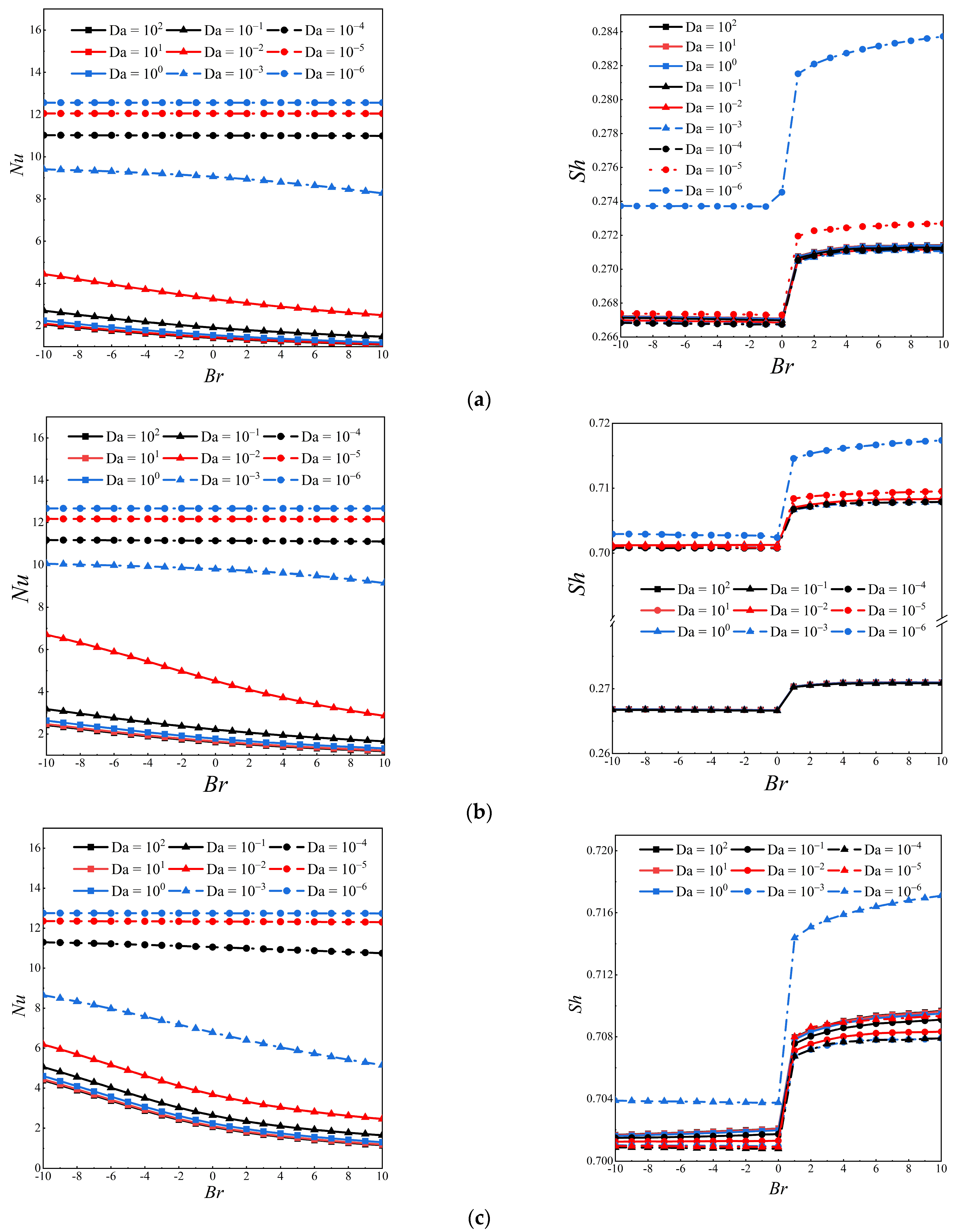
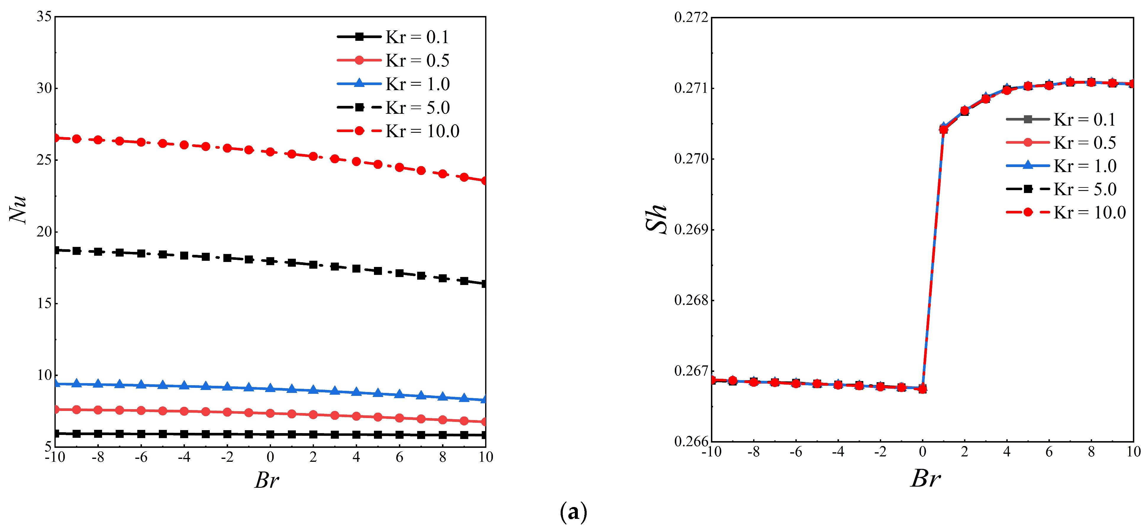
4.1.1. Influence of Permeability and Buoyancy Ratio of Porous Blocks

In this section, the effect of Darcy number and porosity ratio on heat and moisture transportation is presented. The Richardson number, Reynolds number, buoyancy ratio, and porous-fluid thermal conductivity ratio are kept constant at 1.0, 500, 1.0, and 1.0, respectively. Figure 6 shows the influence of different Darcy numbers and buoyancy ratios on the Nu and Sh of discrete, semi-discrete, and polymeric porous media configurations. The convective heat transfer capacity does not change at Da = 10−1, 100, 101, and 102, as the overall convection is weak; this is because the porous media acts as a great barrier to the fluid flow when it reaches the west number, which suppresses the change of convective heat transfer in the cavity. With the decrease in the Darcy number, the permeability of the porous media increases. The overall Nu of the three working conditions increases with the decrease of the Darcy number. The convective heat transfer capacity in the cavity is significantly enhanced, which is conducive to the discharge of pollutants and heat. In addition, when Da = 10−6, 10−5, and 10−4, the arrangement of the three porous media is not affected by Br, the change of Nu tends to be constant, and different Nu curves almost coincide with each other. When Da = 10−3, and 10−2, the Nu decreases with the increase of the buoyancy ratio. The synergy of heat and mass buoyancy suppresses the convective heat transfer capacity in the cavity, and the fluid flows out from the outlet rapidly. Longitudinal comparison of Type A, Type B, and Type C shows that when Da is lower or higher (Da < 10−4 or Da > 10−1), the overall Nu does not change with the distribution of porous media. Under the arrangement modes, Type A and Type B, the change in Nu and Sh is the most similar, and the overall Nu under the arrangement mode of Type C is slightly lower than that of Type A and Type B. In addition, the change in Sh in the cavity has a significant turning point at Br = 0. Under the Type C arrangement, the Sh value is higher than in the other two arrangements; the potential pollutants in the cavity are more conducive to being removed. The change in Da value is slightly more than that of other working conditions at 10−6; this implies that the influence of Darcy number on moisture transfer is weak.

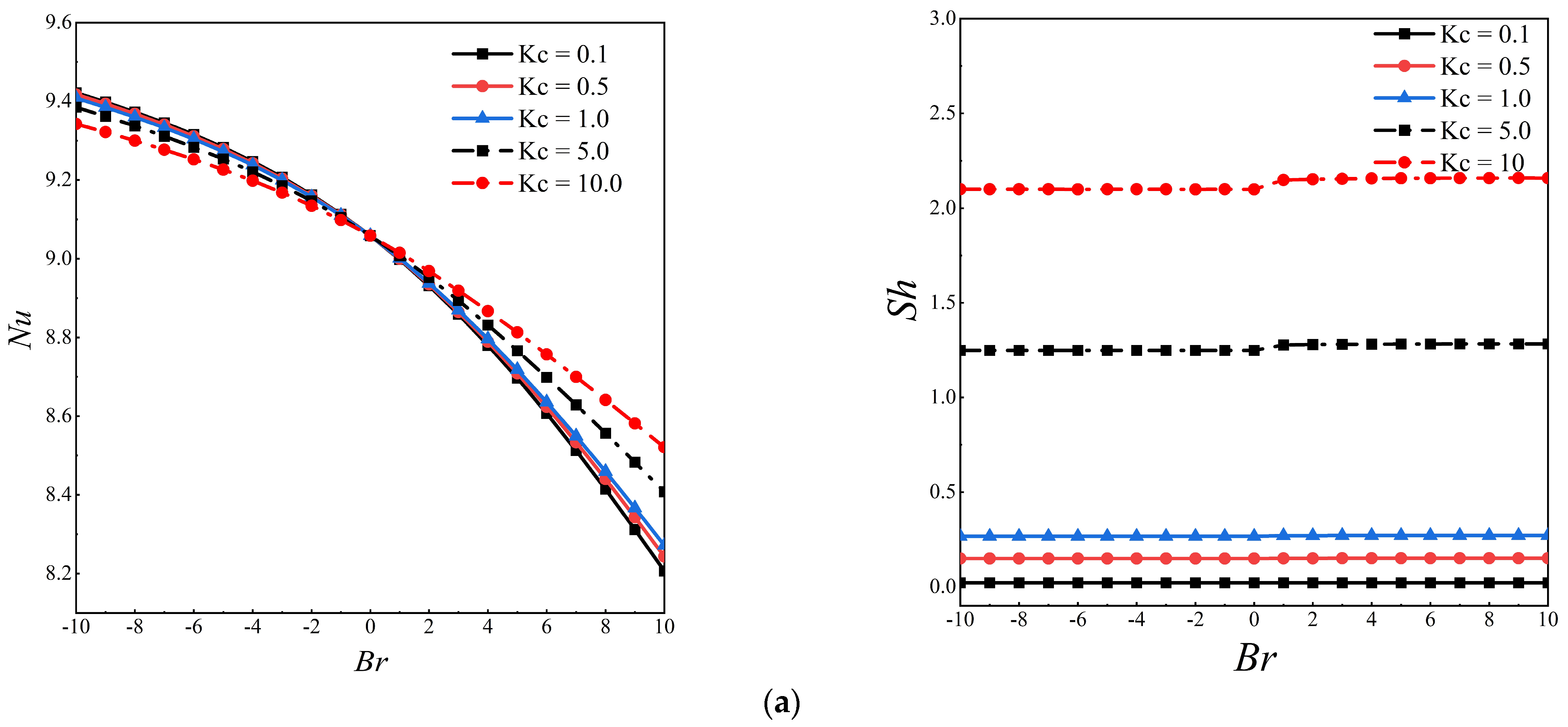
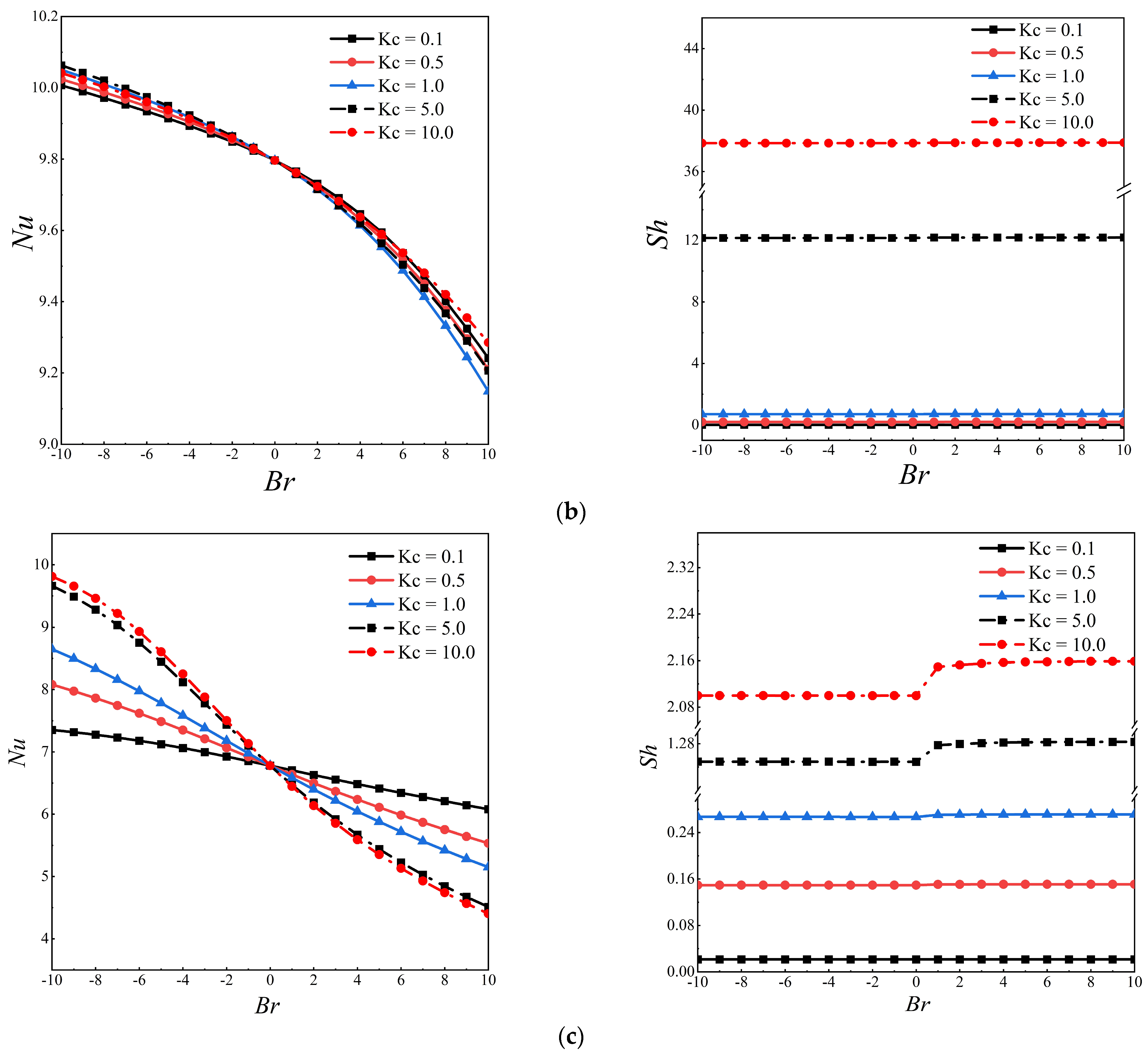
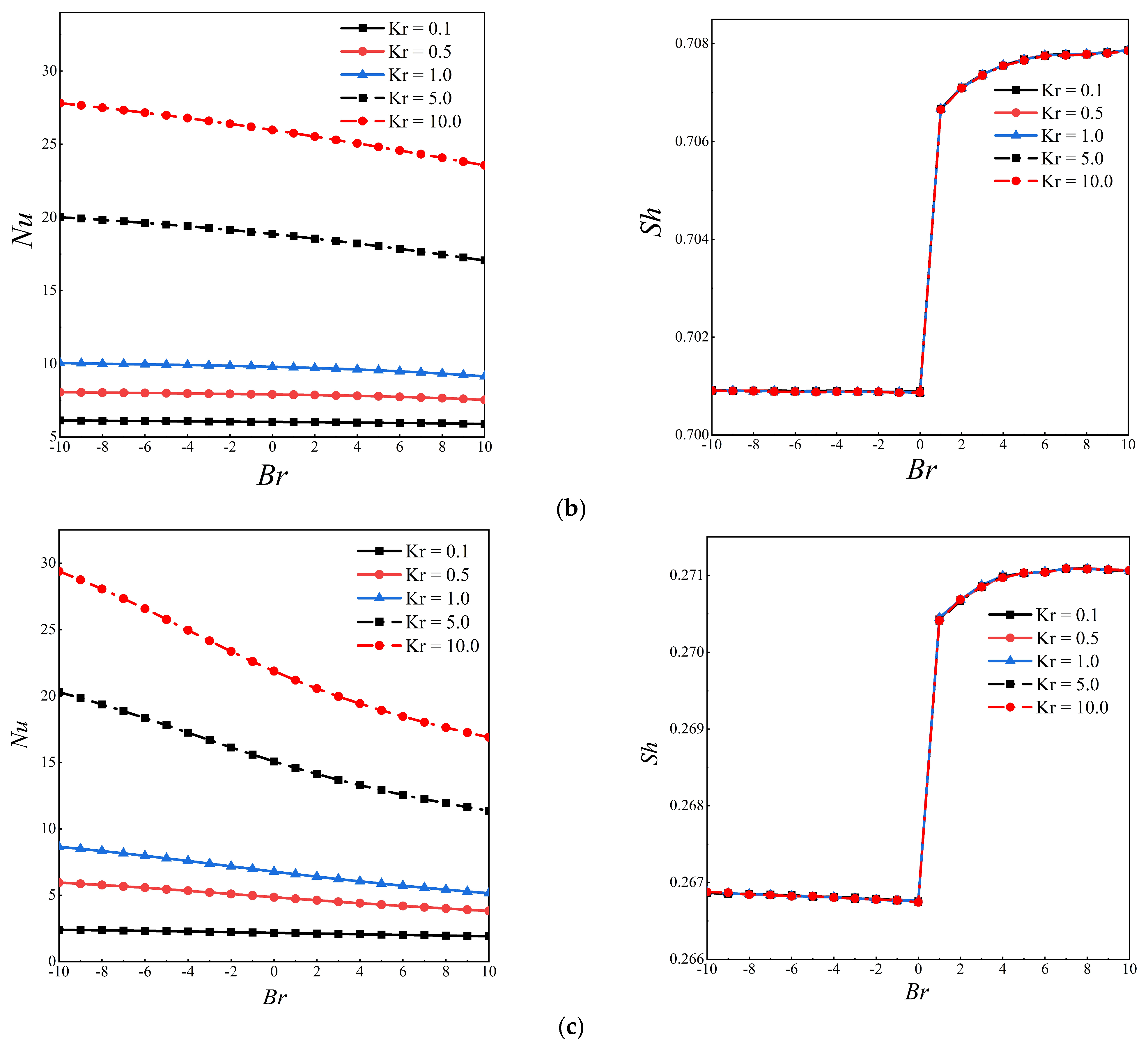
4.1.2. Influence of Porous-Fluid Thermal Conductivity Ratio and Porous Media Mass Conductivity Ratio

In this section, the effect of porous-media mass conductivity ratio Kc and porous-fluid thermal conductivity ratio Kr on the heat transfer and mass transfer capacity in the cavity is described. Da, Re, and Ri are fixed at 10−3, 500, and 1, respectively. Figure 7 shows the relationship between the evolution of heat and moisture transfer in the cavity and the buoyancy ratio under different Kc. As shown in Figure 7a, the overall Nu slightly increases at higher Kc but has no significant effect at lower Kc. When Kc < 1.0 and Br > 0, the Nu value does not change with the change in Kc and Br, indicating that the lower Kc does not affect the heat transfer in the cavity. In addition, the overall Nu decreases with the increase in the Br value, which is consistent with the trend shown in Figure 6. The change in Sh is only related to Kc. There is no evident change in the Sh value when Kc is less than 1.0; however, when Kc = 5.0 and 10, the Sh value exhibits a significant increase. At Br = 0, Sh has a slight increase; this implies that the buoyancy ratio greater than 0 contributes to the moisture transfer in the cavity. Similarly, Figure 7b shows a semi-discrete distribution with Nu and Sh values similar to those in Figure 7a. Under this porous media arrangement, the change in Kc does not affect the convective heat transfer in the cavity, the change in Sh values is the same as that of the discrete porous media arrangement, and, therefore, this is not repeated herein. Figure 7c shows that the distribution of heat exchange and moisture exchange capacity of the polymeric porous media is significantly different from that of Type A and Type B. The overall Nu decreases with the increase in Br, but transition occurs at Br = 0. Nu increases with the increase of Kc when Br < 0, and Nu decreases with the increase in Kc when Br > 0. This implies that the influence of the buoyancy ratio should be considered when porous media is arranged in the cavity as polymeric media. The optimum Kc should be adopted for different buoyancy ratios to maximize the convective heat transfer capacity. Similarly, the Sh values stay almost constant with the change in Br; an ideal Sh can be obtained at a higher Kc value.
Figure 8 depicts the influence of Kr and Br on the Nu and Sh of the three arrangements of porous media. A change in Kr increases Nu significantly. At Kr = 10.0, the Nu values for the three types of arrangement conditions are more than 20; this indicates that it is beneficial to transfer heat in the cavity for a large heat conductivity ratio of porous media. As depicted in Figure 8a,b, Kr is not affected by Br, and the Nu value is linearly affected by Kr. However, in Figure 8c, when Kr > 5.0 Nu decreases with the increase of Br. Therefore, to obtain a higher Nu at a higher Kr value, a lower level of Br must be ensured. In addition, the Sh value does not change regardless of Kr; this implies that the thermal conductivity ratio of porous media would not affect moisture transport.

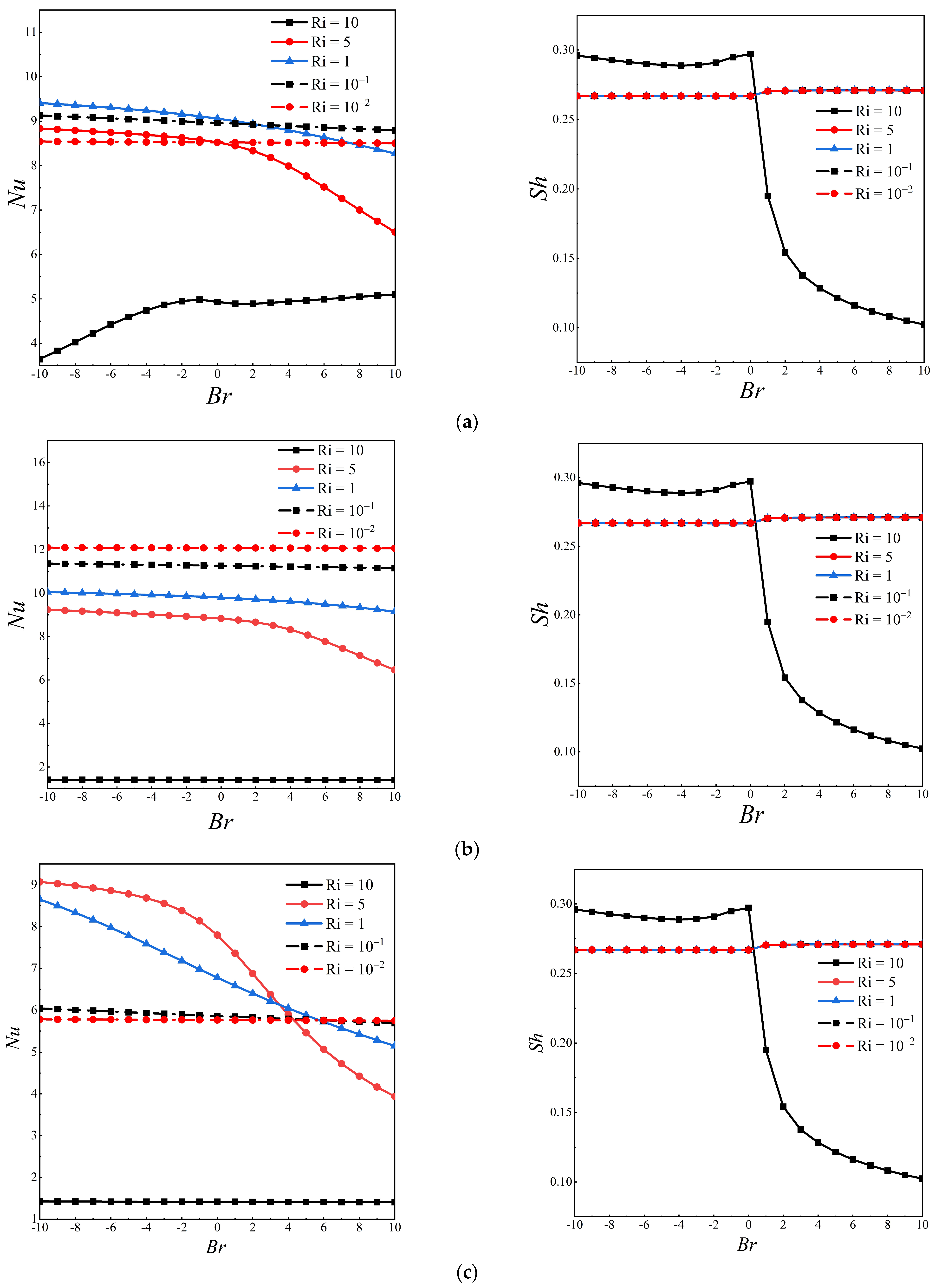
4.1.3. Influence of Richardson Number

The change in Ri influences whether the convection heat transfer in the cavity is dominated by thermal buoyancy or shear force. This section describes the influence of Nu and Br on the arrangement of the three porous media under the condition of changing the dominant driving force in the cavity. Da, Br, Kc, and Kr are fixed at 10−3, 1, 1, and 1, respectively. It can be seen from Figure 9a that when Ri = 10, i.e., the thermal plume dominates in the cavity, Nu increases with the increase in buoyancy ratio. However, Figure 9b,c shows that Nu does not vary with the buoyancy ratio when Ri = 10; this implies that the heat transfer dominated by the thermal plume is affected by the buoyancy ratio only when the porous media is distributed discretely. Figure 9b shows that the Nu value increases gradually with the decrease in the Ri value. However, this change is not observed in Figure 9a,b. The change occurs at about Br = 4, and heat transfer in the cavity would deteriorate at a lower Ri corresponding to Br > 4. This aspect should be considered in engineering design. As shown in the change curve of the Sh, the water transfer in the cavity would be affected by the buoyancy ratio only when Ri = 10, and when Br > 0, the Sh value would fall back rapidly, and the transport capacity would be reduced.

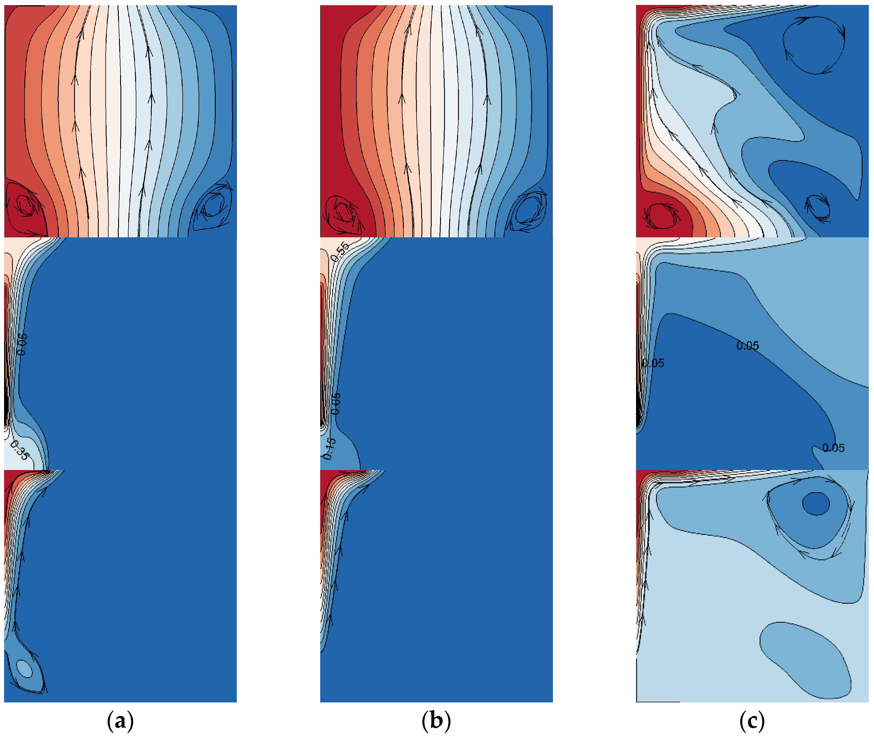
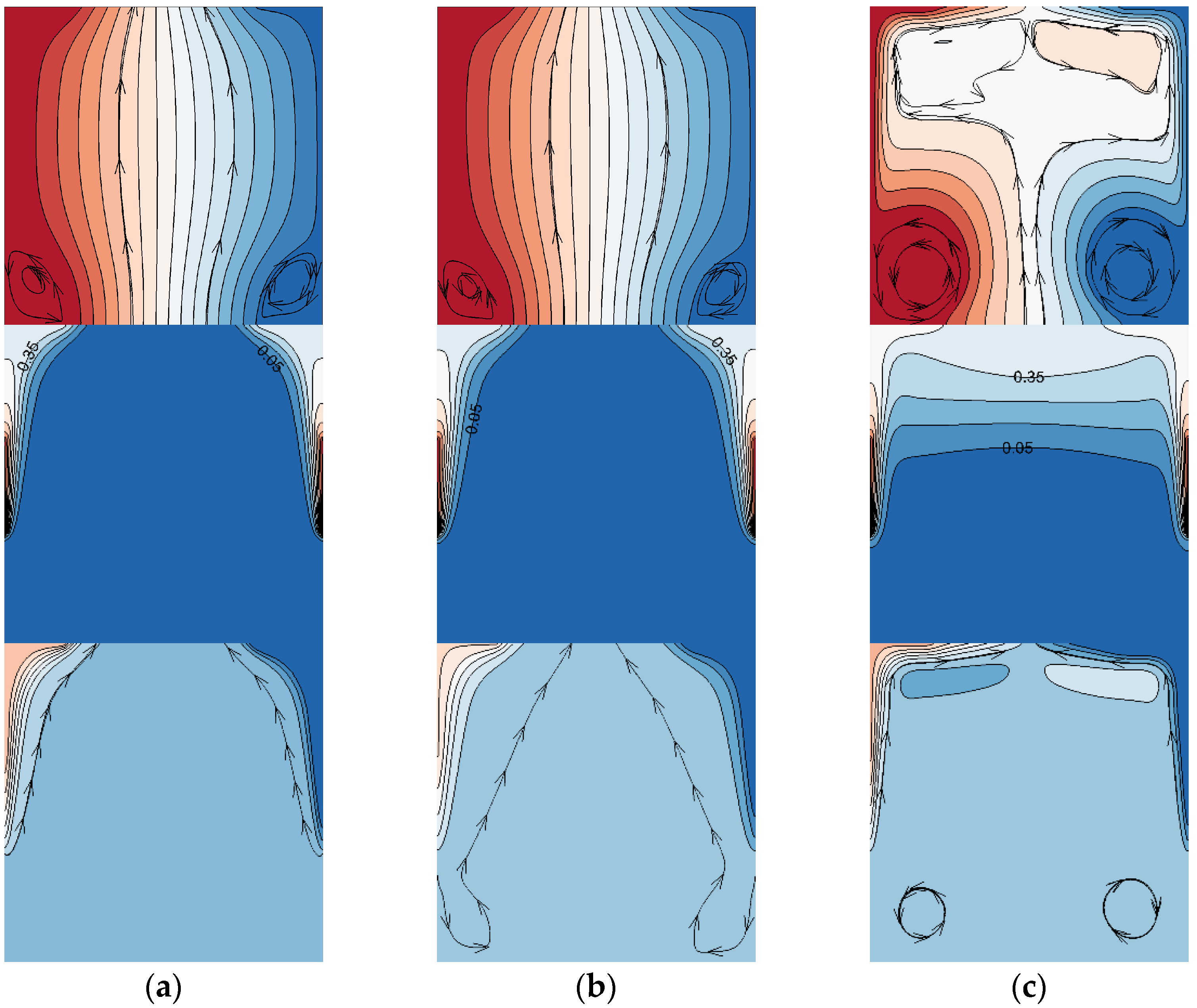
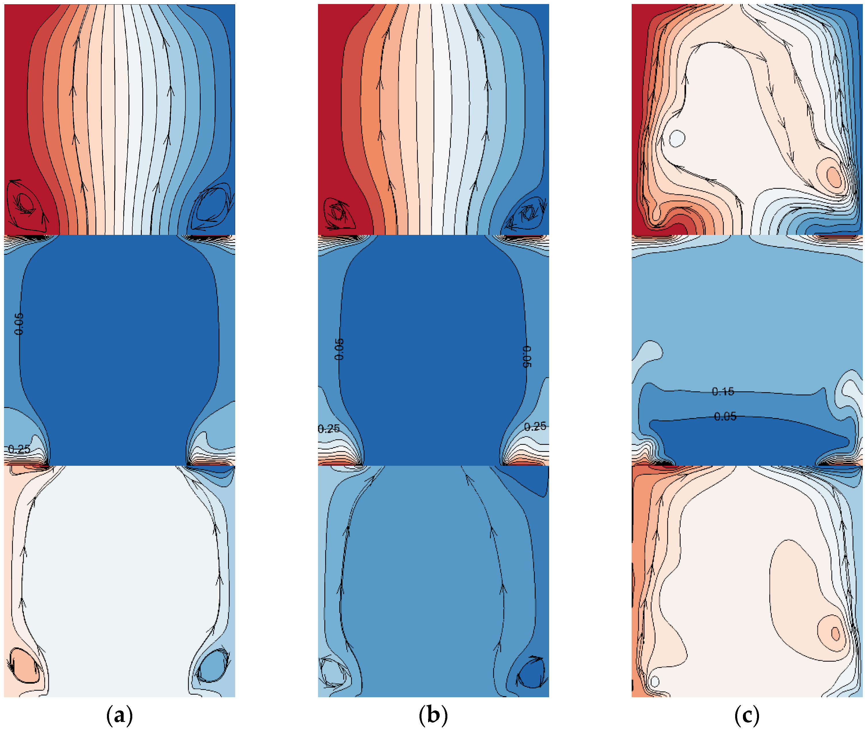
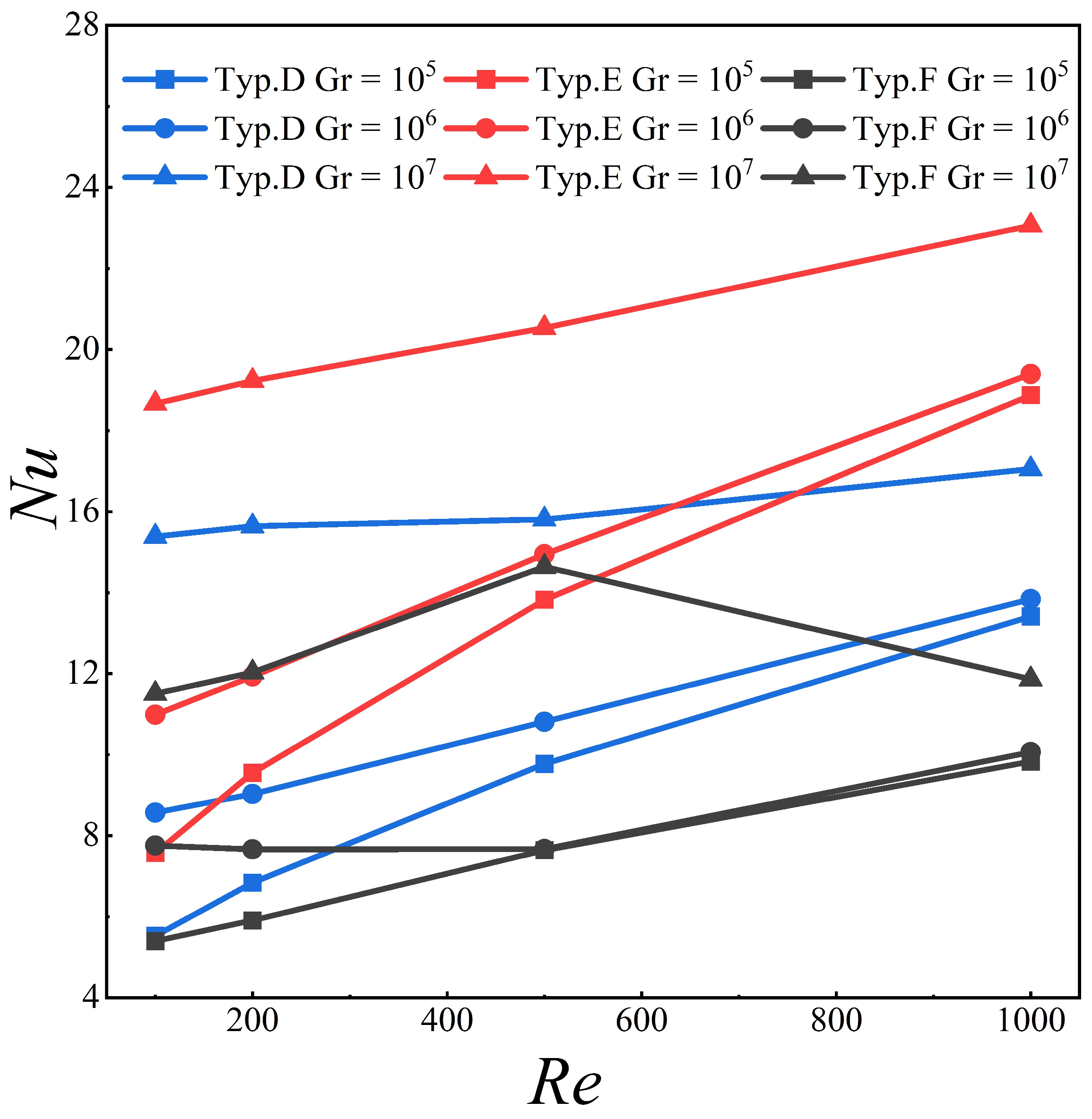
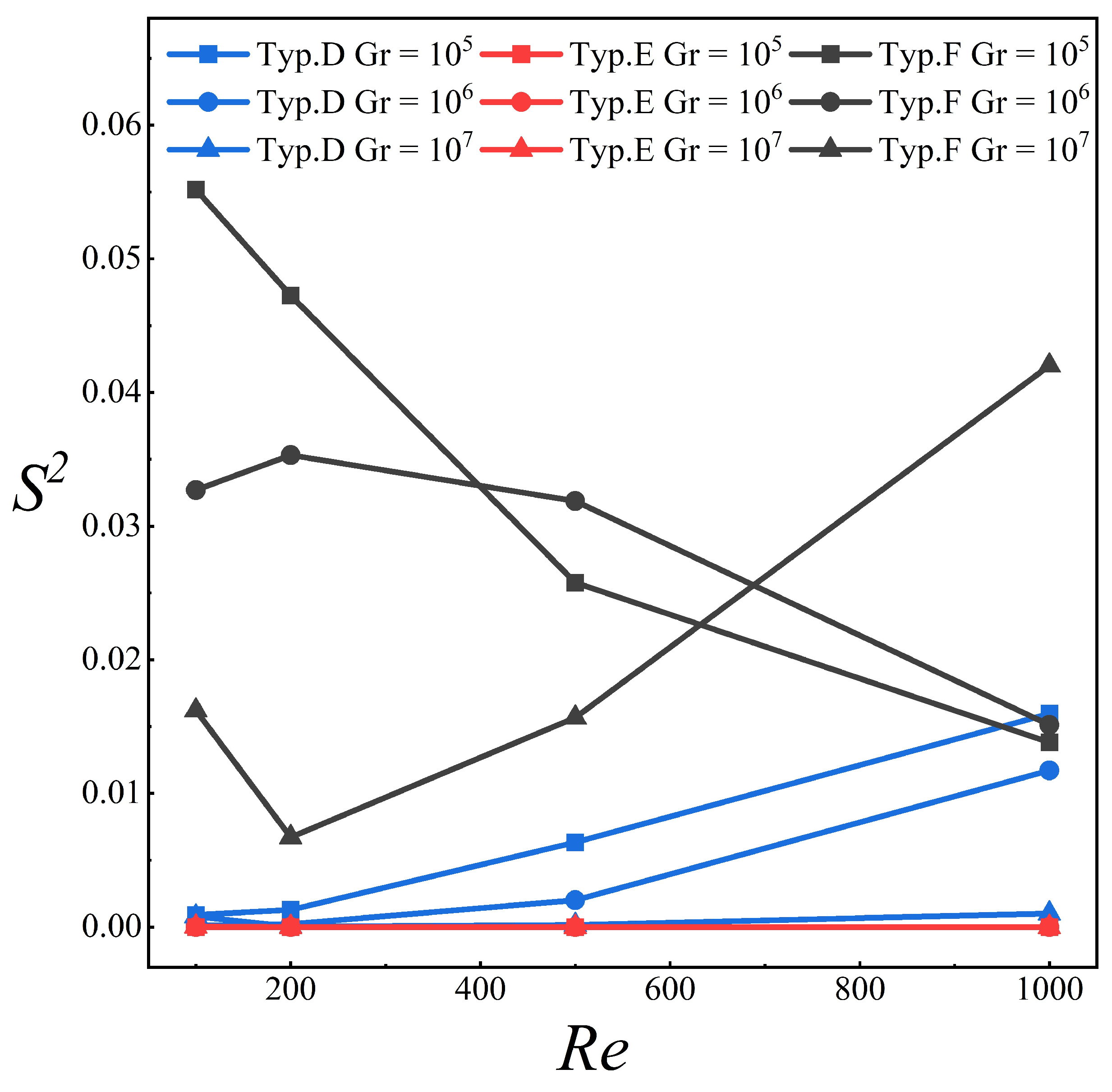
4.2. Centralized, Symmetrical, and Surrounded Hot-Plate Arrangement

As shown in Figure 2b, three different kinds of hot plate arrangements have been discussed in the study, namely, Types D, E, and F. The total heat flux is the same for each arrangement. However, for Type D, only one hot plate is attached to the left inner wall; for Type E, two hot plates are symmetrically attached to the right and left side of the inner wall; and for Type F, four hot plates are symmetrically attached to the top and bottom inner wall of the pre-heated cavity. The gaseous waste is blown into the pre-heated cavity from the bottom with a set velocity.
The primary motivation for the work in this section is, firstly, to obtain a better understanding of the heat transfer process and temperature distribution characteristics under the combined effect of buoyancy and inertia inside the pre-heated cavity; and secondly, to evaluate the uniformity of outflow temperature under different hot-plate arrangements using standard deviation analysis. Figure 10, Figure 11 and Figure 12 present streamlines, isotherms, and heatlines for the three hot plate arrangements. The impact of the buoyancy and inertia is characterized by the Ri value, which reflects the ratio of buoyancy and inertia. Ri is set to 0.1, 4 and 1000 for scenarios (a), (b), and (c) respectively.
Figure 10 shows streamlines, isotherms, and heatlines with increasing R i for Type D. The hot plate is placed on the right inner wall of the cavity. For the small value of Ri, scenarios (a) and (b), it is clear that the streamlines are still symmetric due to the inertia of inlet gaseous-waste flow, and the impact of buoyancy is limited. The same can also be observed from isotherms and heatlines; only a small region near the hot plate is heated. Scenario (c) shows a different distribution of the streamlines, isotherms, and heatlines. The Ri is 1000; thus, the intensity of the buoyant force is more pronounced than the inertia. The strong heat flux on the left region of the cavity induces a clockwise vortex in the right-upper region and the inlet gaseous-waste flow is pushed to the region. As more heat is transferred from the heat source to the whole cavity and the retention time of the gaseous-waste flow is longer, the average temperature for scenario (c) is higher than the other two scenarios.
Figure 11 shows the contours of streamlines, isotherms, and heatlines for Type E, with two symmetric heat sources attached to the left and right inner walls of the cavity. The global flow and the temperature field are symmetric. Similar to Type D, for low Ri, e.g., Ri  = 0.1 and Ri  = 4 , the gaseous waste flows through the cavity; only the region near the heat source is heated. Some heat is transferred from the heat source to the bottom of the cavity on increasing Ri. The temperature field inside the cavity is almost the same for scenarios (a) and (b). When the Ri reaches 1000, two vertexes are formed in the bottom of the cavity; however, the heat transfer is not enhanced by the two vertexes. The contours of isotherms clearly show that the lower part of the cavity remains at ambient temperature.
The contours of streamlines, isotherms, and heatlines for Type F, with four hot plates attached to the top and bottom of the cavity, are shown in Figure 12. For Ri  = 0.1 and Ri = 4 , a symmetric flow and temperature field with low temperatures are observed. The reason is the same as in scenarios (a) and (b). The gaseous waste with high inertia flow tends to flow out of the cavity directly; the heat source and buoyancy hardly have any impact on temperature and flow field. With an increased Ri, both the heat flux and retention time of the gaseous waste increase and thus, a higher temperature is found.
Figure 10, Figure 11 and Figure 12 present the temperature and flow field with different hot-plate arrangements as well as the heat transfer process varying with R i . With the increase in R i , the gaseous waste flow changes from inertia-dominated flow to buoyancy-dominated flow.
Figure 13 shows the dependence of Nu on Re for Type D, Type E, and Type F. Here, Nu reflects the convective heat transfer efficiency of the cavity. First, we observe that the Nu is higher with a higher Gr for the same Re number. Second, the variation gradient of Nu increases with the Gr number. Nu for Gr = 106 and Gr  = 10 7 is almost the same when Re = 1000. This shows that for inertia-driven flow, increasing Gr has little impact on Nu. On the contrary, a considerable increase in Nu is observed when increasing Gr at small Re values, which denote a buoyancy-driven flow. Specifically, the increase of Nu with Re is more significant for Type E, shown as the steepest red lines in Figure 13. Thirdly, the convective heat transfer efficiency is higher for Type E in general, contrary to our expectations of Type F having a higher heat exchange efficiency, as the hot plates are better distributed for Type F. This can be rationalized from the observations presented in Figure 14, which shows that two vertexes are formed in the bottom corners of the cavity, on increasing Re resulting in a decreased involvement of heat from the hot plates in convective heat transfer, and thus, a sharp decrease in Nu for Re = 1000.
Figure 14 depicts the uniformity of temperature distribution inside the cavity for each type of arrangement. The temperature difference gradient is significant for Type F regardless of the Re number. The temperature is relatively more uniform for Type E than for the other two types. This is in agreement with the temperature fields presented in Figure 10, Figure 11 and Figure 12. The type E arrangement is more efficient in improving the adsorption efficiency for achieving uniform temperature distribution.

5. Conclusions

In this study, two-dimensional heat and mass transfer simulations were performed. The impact of different distributions of porous media, hot plate arrangement, heat flux, and inlet gaseous waste velocity on the adsorption efficiency for a preheating cavity was analyzed. The main results obtained in this investigation are summarized as follows:
(1)
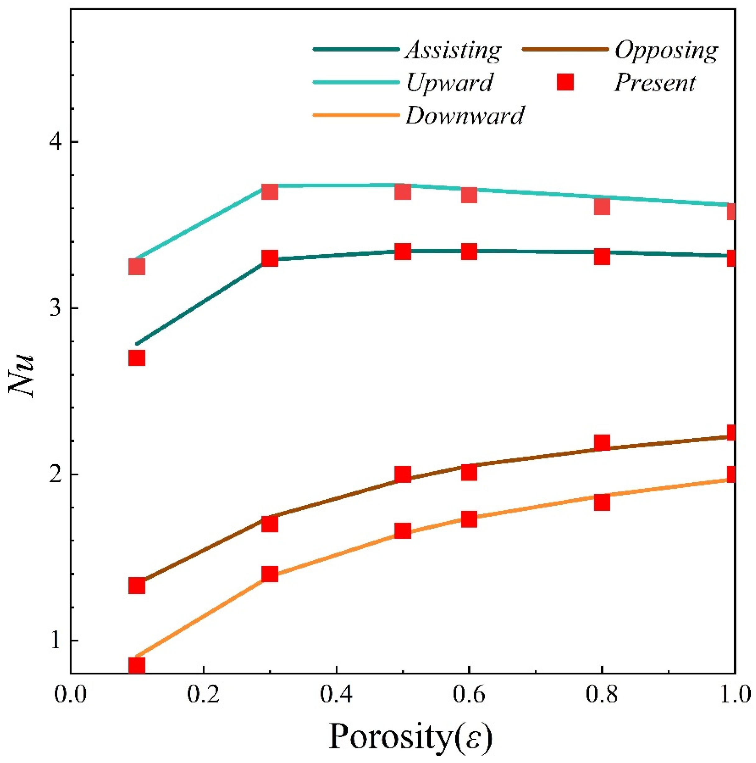
It was found that the heat transfer mechanisms and the flow characteristics inside the enclosure are strongly dependent on the permeability of the porous media and buoyancy ratio. Increasing the porosity is conducive to enhancing convection heat transfer. The highest Nusselt number was found when Da = 10−6 and Kr = 10.
(2)
The porous media arrangement has a considerable impact on convective heat transfer. The polymeric porous media exhibited better heat transfer performance than the other two porous media arrangements discussed in the present paper. The average Nusselt number increased by about 10%.
(3)
The study of the impact of hot-plate layout on convective heat transfer shows that the location of the hot plates has a more significant impact on convective heat transfer than the number of hot plates in the cavity. The convective heat transfer of Type F, which has four hot plates well-distributed inside the cavity, has the lowest convective heat transfer efficiency (Nu number) for the same heat flux and inlet gas velocity (Ri number). Instead, the convective heat transfer is more pronounced for Type E, which has two hot plates. The convective heat transfer efficiency of Type E is about 110% higher than that of Type F and it is about 35% higher than that of Type D. From this point of view, installing the hot plates parallel to the streamline is beneficial to the convective heat transfer. The temperature variance also indicates that the temperature distribution of Type E is more uniform.

Author Contributions

Writing—original draft, Validation, Visualization, J.L.; Investigation, Software, Data curation, Y.-C.C.; Formal analysis, Methodology, Software, J.H.; Writing—review & editing, Conceptualization, H.X.; Project administration, Supervision, F.-Y.Z.; Methodology, Writing—review & editing, J.-H.G. All authors have read and agreed to the published version of the manuscript.

Funding

Authors would gratefully acknowledge the financial supports of Wuhan Application Foundation and Cutting-edge Research Plan (Grant NO. 2020010601012206, Wuhan University), Fundamental Research Funds for the Central Universities (Grant NO. 2042021KF0028, Wuhan University), Science and Technology Innovation Program of Hunan Province (Grant NO. 2020RC4032, Hunan University of Technology), Wuhan University Specific Fund for Major School-Level Internationalization Initiatives (Grant NO. WHU-GJZDZX-PT08, Wuhan University), and Provincial Key R&D Program of Hunan (Grant NO. 2022SK2084, Hunan University of Technology).

Data Availability Statement

All referenced data exists within the paper.

Conflicts of Interest

The authors declare no conflict of interest.

Nomenclature

dporous media thickness (m)
Dmass diffusivity (m2/s)
DaDarcy number
ggravitational acceleration(m/s2)
GrGrashof number
kthermal conductivity (W/(m·K))
kTCthermodiffusion coefficient (m5⋅K⋅kg−1⋅s−1)
kCTdiffusionthermo coefficient (kg⋅m−1⋅K−1⋅s−1)
Kpermeability of porous media (m2)
Krthermal conductivity ratio
Kcmass diffusion coefficient ratio
Llength of enclosure(m)
LeLewis number
Nuoverall Nusselt number
Pdimensionless pressure
PrPrandtl number
RiRichardson number
S2Variance
Shoverall Sherwood number
Tdimensionless temperature
Tccooling temperature (K)
Thhigh temperature (K)
u0dimensional velocity (m/s)
U0dimensionless velocity
u, vvelocity components in x, y directions
U, Vdimensionless velocity components
Wwidth of enclosure (m)
x, yCartesian coordinate (m)
X, Ydimensionless Cartesian coordinates
Greeks
athermal diffusivity (m2/s)
βthermal expansion (K−1)
δstop criterion
λthermal conductivity (W/m·K)
μdynamic viscosity (kg/m·s)
νkinematic viscosity (m2/s)
ρdensity (kg/m3)
Ψstreamfunction
Θheatfunction
Subscripts
ccooling temperature
hhot temperature

References

  1. Doll, C.G.; Sorensen, C.M.; Bowyer, T.W.; Friese, J.I.; Hayes, J.C.; Hoffmann, E.; Kephart, R. Abatement of xenon and iodine emissions from medical isotope production facilities. J. Environ. Radioact. 2014, 130, 33–43. [Google Scholar] [CrossRef]
  2. Bowyer, T.W. A review of global radioxenon background research and issues. Pure Appl. Geophys. 2021, 178, 2665–2675. [Google Scholar] [CrossRef]
  3. Bowyer, T.W.; Kephart, R.; Eslinger, P.W.; Friese, J.I.; Miley, H.S.; Saey, P.R. Maximum reasonable radioxenon releases from medical isotope production facilities and their effect on monitoring nuclear explosions. J. Environ. Radioact. 2013, 115, 192–200. [Google Scholar] [CrossRef]
  4. Choi, C.-J.; Cho, H.K. Numerical Investigations of Liquid Film Offtake by Transverse Gas Flow in a Downcomer Annulus Geometry. Front. Energy Res. 2022, 2, 285. [Google Scholar] [CrossRef]
  5. Achim, P.; Generoso, S.; Topin, S.; Gross, P.; Monfort, M.; Moulin, C.; Le Petit, G.; Douysset, G.; Morin, M. 6 months of radioxenon detection in western Europe with the SPALAX-New generation system—Part 2: Atmospheric transport modelling. J. Environ. Radioact. 2021, 226, 106455. [Google Scholar]
  6. Yu, S.; Liu, Y.; Chen, S.; Bai, Y. Analysis of Process Parameters of Gaseous Radwaste Treatment by Activated Charcoal Delay Beds in Nuclear Power Plants. Nucl. Power Eng. 2015, 36, 116–119. [Google Scholar]
  7. Ringbom, A.; Axelsson, A.; Björnham, O.; Brännström, N.; Fritioff, T.; Grahn, H.; Hennigor, S.; Olsson, M. Radioxenon releases from a nuclear power plant: Stack data and atmospheric measurements. Pure Appl. Geophys. 2021, 178, 2677–2693. [Google Scholar] [CrossRef] [Green Version]
  8. Du, Y.; Wang, S.; Li, D.; Peng, Y.; Yang, L. Effect of evaporation rate for the heat and mass transfer of laminar liquid falling film in still air. Front. Energy Res. 2022, 10, 1291. [Google Scholar] [CrossRef]
  9. Sameh, A.-H.A. Production cycle for large scale fission Mo-99 separation by the processing of irradiated LEU uranium silicide fuel element targets. Sci. Technol. Nucl. Install. 2013, 2013, 704846. [Google Scholar]
  10. Juan, Y.; Ke-qiang, Q. Preparation of Activated Carbon by Chemical Activation under Vacuum. Environ. Sci. Technol. 2009, 43, 3385–3390. [Google Scholar] [CrossRef]
  11. Dombrowski, R.J.; Hyduke, D.R.; Lastoskie, C.M. Pore Size Analysis of Activated Carbons from Argon and Nitrogen Porosimetry Using Density Functional Theory. Langmuir 2000, 16, 5041–5050. [Google Scholar] [CrossRef]
  12. Underhill, D.W. Calculation of the Performance of Activated Carbon at High Relative Humidities. Am. Ind. Hyg. Assoc. J. 1987, 48, 909–913. [Google Scholar] [CrossRef] [PubMed]
  13. Ali, F.H.; Hamzah, H.K.; Hussein, A.K.; Jabbar, M.Y.; Talebizadehsardari, P. MHD mixed convection due to a rotating circular cylinder in a trapezoidal enclosure filled with a nanofluid saturated with a porous media. Int. J. Mech. Sci. 2020, 181, 105688. [Google Scholar] [CrossRef]
  14. Kareem, A.K.; Mohammed, H.A.; Hussein, A.K.; Gao, S. Numerical investigation of mixed convection heat transfer of nanofluids in a lid-driven trapezoidal cavity. Int. Commun. Heat Mass Transf. 2016, 77, 195–205. [Google Scholar] [CrossRef] [Green Version]
  15. Sivasankaran, S.; Sivakumar, V.; Hussein, A.K. Numerical study on mixed convection in an inclined lid-driven cavity with discrete heating. Int. Commun. Heat Mass Transf. 2013, 46, 112–125. [Google Scholar] [CrossRef]
  16. Nazeer, M.; Ali, N.; Javed, T. Numerical simulations of MHD forced convection flow of micropolar fluid inside a right-angled triangular cavity saturated with porous medium: Effects of vertical moving wall. Can. J. Phys. 2019, 97, 1–13. [Google Scholar] [CrossRef]
  17. Nazeer, M.; Ahamdi, A.A.A.; Alzaed, A.N.; Alwetaishi, M.; Nazir, M.W.; Khan, M.I. Impact of slip boundary conditions, magnetic force, and porous medium on blood flow of Jeffrey fluid. ZAMM J. Appl. Math. Mech. 2022, 102, e202100218. [Google Scholar] [CrossRef]
  18. Chamkha, A.J. Non-darcy fully developed mixed convection in a porous medium channel with heat generation/absorption and hydromagnetic effects. Numer. Heat Transf. Part A Appl. 1997, 32, 653–675. [Google Scholar] [CrossRef]
  19. Selimefendigil, F.; Ismael, M.A.; Chamkha, A.J. Mixed convection in superposed nanofluid and porous layers in square enclosure with inner rotating cylinder. Int. J. Mech. Sci. 2017, 124–125, 95–108. [Google Scholar] [CrossRef]
  20. Laidoudi, H.; Mohamed, B. Mixed convection heat transfer from confined tandem circular cylinders in cross-flow at low Reynolds number. Mechanika 2017, 23, 522–527. [Google Scholar]
  21. Rashid, F.L.; Hussein, A.K.; Malekshah, E.H.; Abderrahmane, A.; Guedri, K.; Younis, O. Review of Heat Transfer Analysis in Different Cavity Geometries with and without Nanofluids. Nanomaterials 2022, 12, 2481. [Google Scholar] [CrossRef]
  22. Kasmani, R.M.; Sivasankaran, S.; Bhuvaneswari, M.; Hussein, A.K. Analytical and numerical study on convection of nanofluid past a moving wedge with Soret and Dufour effects. Int. J. Numer. Methods Heat Fluid Flow 2017, 27, 2333–2354. [Google Scholar] [CrossRef]
  23. Nazeer, M.; Ali, N.; Javed, T.; Nazir, M.W. Numerical analysis of the full MHD model with the Galerkin finite-element method. Eur. Phys. J. Plus 2019, 134, 204. [Google Scholar] [CrossRef]
  24. Ali, N.; Nazeer, M.; Javed, T.; Razzaq, M. Finite element analysis of bi-viscosity fluid enclosed in a triangular cavity under thermal and magnetic effects. Eur. Phys. J. Plus 2019, 134, 2. [Google Scholar] [CrossRef]
  25. Ismael, M.A. Double-diffusive mixed convection in a composite porous enclosure with arc-shaped moving wall: Tortuosity effect. J. Porous Media 2018, 21, 343–362. [Google Scholar] [CrossRef]
  26. Ghachem, K.; Kolsi, L.; Mâatki, C.; Hussein, A.K.; Borjini, M.N. Numerical simulation of three-dimensional double diffusive free convection flow and irreversibility studies in a solar distiller. Int. Commun. Heat Mass Transf. 2012, 39, 869–876. [Google Scholar] [CrossRef]
  27. Maatki, C.; Ghachem, K.; Kolsi, L.; Hussein, A.K.; Borjini, M.N.; Aissia, H.B. Inclination effects of magnetic field direction in 3D double-diffusive natural convection. Appl. Math. Comput. 2016, 273, 178–189. [Google Scholar] [CrossRef]
  28. Chand, R.; Rana, G.; Hussein, A. On the Onsetof Thermal Instability in a Low Prandtl Number Nanofluid Layer in a Porous Medium. J. Appl. Fluid Mech. 2015, 8, 265–272. [Google Scholar] [CrossRef]
  29. Ali, B.; Hussain, S.; Nie, Y.; Hussein, A.K.; Habib, D. Finite element investigation of Dufour and Soret impacts on MHD rotating flow of Oldroyd-B nanofluid over a stretching sheet with double diffusion Cattaneo Christov heat flux model. Powder Technol. 2021, 377, 439–452. [Google Scholar] [CrossRef]
  30. Nazeer, M.; Ali, N.; Javed, T. Numerical simulation of MHD flow of micropolar fluid inside a porous inclined cavity with uniform and non-uniform heated bottom wall. Can. J. Phys. 2018, 96, 576–593. [Google Scholar] [CrossRef] [Green Version]
  31. Nazir, M.W.; Javed, T.; Ali, N.; Nazeer, M.; Khan, M.I. Theoretical investigation of thermal analysis in aluminum and titanium alloys filled in nanofluid through a square cavity having the uniform thermal condition. Int. J. Mod. Phys. B 2022, 36, 2250140. [Google Scholar] [CrossRef]
  32. Nazir, M.W.; Javed, T.; Ali, N.; Nazeer, M. Effects of radiative heat flux and heat generation on magnetohydodynamics natural convection flow of nanofluid inside a porous triangular cavity with thermal boundary conditions. Numer. Methods Partial. Differ. Equ. 2021, 14, 1–18. [Google Scholar] [CrossRef]
  33. Ali, N.; Nazeer, M.; Javed, T. Finite element simulations of free convection flow inside a porous inclined cavity filled with micropolar fluid. J. Porous Media 2021, 24, 57–75. [Google Scholar] [CrossRef]
  34. Nazeer, M.; Ali, N.; Javed, T. Natural convection flow of micropolar fluid inside a porous square conduit: Effects of magnetic field, heat generation/absorption, and thermal radiation. J. Porous Media 2018, 21, 953–975. [Google Scholar] [CrossRef]
  35. Al-Hassan, A.Q.A.; Ismael, M.A. Numerical study of double diffusive mixed convection in horizontal channel with composite open porous cavity. J. Porous Media 2019, 10, 401–419. [Google Scholar] [CrossRef]
  36. Ismael, M.A.; Ghalib, H.S. Double diffusive natural convection in a partially layered cavity with inner solid conductive body. Sci. Iran. 2018, 25, 2643–2659. [Google Scholar] [CrossRef] [Green Version]
  37. Alsabery, A.I.; Mohebbi, R.; Chamkha, A.J.; Hashim, I. Effect of local thermal non-equilibrium model on natural convection in a nanofluid-filled wavy-walled porous cavity containing inner solid cylinder. Chem. Eng. Sci. 2019, 201, 247–263. [Google Scholar] [CrossRef]
  38. Ghalambaz, M.; Jamesahar, E.; Ismael, M.A.; Chamkha, A.J. Fluid-structure interaction study of natural convection heat transfer over a flexible oscillating fin in a square cavity. Int. J. Therm. Sci. 2017, 111, 256–273. [Google Scholar] [CrossRef]
  39. Ben-Nakhi, A.; Chamkha, A.J. Effect of length and inclination of a thin fin on natural convection in a square enclosure. Numer. Heat Transf. Part A Appl. 2006, 50, 381–399. [Google Scholar] [CrossRef]
  40. Chamkha, A.J.; Al-Naser, H. Double-diffusive convection in an inclined porous enclosure with opposing temperature and concentration gradients. Int. J. Therm. Sci. 2001, 40, 227–244. [Google Scholar] [CrossRef]
  41. Chamkha, A.J. Double-diffusive convection in a porous enclosure with cooperating temperature and concentration gradients and heat generation or absorption effects. Numer. Heat Transf. Part A Appl. 2002, 41, 65–87. [Google Scholar] [CrossRef] [Green Version]
  42. Dogonchi, A.S.; Ismael, M.A.; Chamkha, A.J.; Ganji, D.D. Numerical analysis of natural convection of Cu–water nanofluid filling triangular cavity with semicircular bottom wall. J. Therm. Anal. Calorim. 2019, 135, 3485–3497. [Google Scholar] [CrossRef]
  43. Khanafer, K.M.; Chamkha, A.J. Hydromagnetic natural convection from an inclined porous square enclosure with heat generation. Numer. Heat Transf. Part A Appl. 1998, 33, 891–910. [Google Scholar] [CrossRef]
  44. Tabasi, M.; Ghannadi-Maraghehl, M.; Shamsaii, M.; Khanchi, A.R. Separation of 133Xe from 99Mo, 131I and uranium, and removal of impurities using gas chromatography. J. Radioanal. Nucl. Chem. 2005, 264, 679–686. [Google Scholar] [CrossRef]
  45. Khanafer, K.; AlAmiri, A.; Bull, J. Laminar natural convection heat transfer in a differentially heated cavity with a thin porous fin attached to the hot wall. Int. J. Heat Mass Transf. 2015, 87, 59–70. [Google Scholar] [CrossRef]
  46. Vafai, K.J. Handbook of Porous Media, 2nd ed.; Routlege: London, UK, 2005. [Google Scholar]
  47. Marafie, A.; Vafai, K. Analysis of non-Darcian effects on temperature differentials in porous media. Int. J. Heat Mass Transf. 2001, 44, 4401–4411. [Google Scholar] [CrossRef]
  48. Mahmoudi, Y.; Karimi, N.; Mazaheri, K. Analytical investigation of heat transfer enhancement in a channel partially filled with a porous material under local thermal non-equilibrium condition: Effects of different thermal boundary conditions at the porousfluid interface. Int. J. Heat Mass Transf. 2014, 70, 875–891. [Google Scholar] [CrossRef] [Green Version]
  49. Noor, M.B.; Omar, R.A.; Ibrahim, A.M. Impact of using single heated obstacle on natural convection inside porous cavity under non-Darcy flow and thermal non-equilibrium model: A comparison between horizontal and vertical heated obstacle arrangements. Int. Commun. Heat Mass Transf. 2022, 133, 105925. [Google Scholar]
  50. Anwar, A.Y.; Omar, R.A.; Asmaa, T.H. Impact of using triple adiabatic obstacles on natural convection inside porous cavity under non-darcy flow and local thermal non-equilibrium model. Int. Commun. Heat Mass Transf. 2022, 130, 105760. [Google Scholar]
  51. Omar, R.A. A thermal nonequilibrium model to natural convection inside non-Darcy porous layer surrounded by horizontal heated plates with periodic boundary temperatures. Heat Transf. 2021, 50, 6068–6098. [Google Scholar]
  52. Omar, R.A.; Noor, M.B.; Anwar, A.Y. Analysis of effects of thermal non-equilibrium and non-Darcy flow on natural convection in a square porous enclosure provided with a heated L shape plate. Int. J. Mech. Sci. 2020, 181, 105704. [Google Scholar]
  53. Omar, R.A. Numerical Investigation of Two-Phase Flow in a Horizontal Porous Evaporator with Localised Heating using Non-Darcian Flow and Two Equations Model. Heat Mass Transf. 2020, 56, 1203–1221. [Google Scholar]
  54. Omar, R.A.; Noor, M.B.; Anwar, A.Y. Natural convection heat transfer from a bank of orthogonal heated plates embedded in a porous medium using LTNE model: A comparison between in-line and staggered arrangements. Int. J. Therm. Sci. 2021, 160, 106692. [Google Scholar]
  55. Alshuraiaan, B.; Khanafer, K. The effect of the position of the heated thin porous fin on the laminar natural convection heat transfer in a differentially heated cavity. Int. Commun. Heat Mass Transf. 2016, 78, 190–199. [Google Scholar] [CrossRef]
  56. Siavashi, M.; Yousofvand, R.; Rezanejad, S. Nanofluid and porous fins effect on natural convection and entropy generation of flow inside a cavity. Adv. Powder Technol. 2018, 29, 142–156. [Google Scholar] [CrossRef]
  57. Xu, H.; Sun, J.Y.; Song, Y.J.; Zhao, F.Y.; Guo, J.H. Multiple hysteresis effects and their destabilization mechanism in the enclosed mixed convection enclosure with three representative aspect ratios. Numer. Heat Transf. Part A: Appl. 2022, 1–31. [Google Scholar] [CrossRef]
  58. Nield, D.A.; Bejan, A. Convection in Porous Media; Springer: New York, NY, USA, 1992. [Google Scholar]
  59. Kousar, N.; Rehman, K.U.; Al-Kouz, W.; Al-Mdallal, Q.M.; Malik, M.Y. Hybrid mesh finite element analysis (HMFEA) of uniformly heated cylinder in a partially heated moon shaped enclosure. Case Stud. Therm. Eng. 2020, 21, 100713. [Google Scholar] [CrossRef]
  60. Kimura, S.; Bejan, A. The “Heatline” Visualization of Convective Heat Transfer. J. Heat Transf. 1983, 105, 916–919. [Google Scholar] [CrossRef]
  61. Zhao, F.Y.; Liu, D.; Tang, G.F. Conjugate heat transfer in square enclosures. Heat Mass Transf. 2006, 43, 907–922. [Google Scholar] [CrossRef]
  62. Liu, D.; Zhao, F.-Y.; Tang, G.-F. Thermosolutal convection in saturated porous enclosure with concentrated energy and solute sources. Energy Convers. Manag. 2008, 49, 16–31. [Google Scholar] [CrossRef]
  63. Hayase, T.; Humphrey, J.A.C.; Greif, R. A consistently formulated QUICK scheme for fast and stable convergence using finite-volume iterative calculation procedures. J. Comput. Phys. 1992, 98, 108–118. [Google Scholar] [CrossRef]
  64. Shi, Y.S.; Liu, D.; Wang, Y.; Zhao, F.Y.; Li, Y.X. Forced flow structure and mixed convection in a ventilated porous enclosure with a local contaminant source. Int. J. Heat Mass Transf. 2019, 131, 973–983. [Google Scholar] [CrossRef]
  65. Zhao, F.-Y.; Liu, D.; Tang, G.-F. Multiple steady fluid flows in a slot-ventilated enclosure. Int. J. Heat Fluid Flow 2008, 29, 1295–1308. [Google Scholar] [CrossRef]
  66. Wei, W.W.; Yang, C.; Lei, W.; Liu, C.W.; Zhao, F.-Y.; Mikhail, A.S.; Di, L. A two-phase closed thermosyphon operated with nanofluids for solar energy collectors: Thermodynamic modeling and entropy generation analysis. Sol. Energy 2020, 211, 192–209. [Google Scholar]
  67. Corcione, M.; Grignaffini, S.; Quintino, A. Correlations for the double-diffusive natural convection in square enclosures induced by opposite temperature and concentration gradients. Int. J. Heat Mass Transf. 2015, 81, 811–819. [Google Scholar] [CrossRef]
  68. Siegmann-Hegerfeld, T.; Albensoeder, S.; Kuhlmann, H.C. Experiments on the stability, structure, and dynamics of flows in one- and two- sided lid-driven cavities. In Proceedings of the 14th International Symposium on Applications of Laser Techniques to Fluid Mechanics, Lisbon, Portugal, 16–19 July 2008. [Google Scholar]
  69. Biswas, N.; Manna, N.K. Enhanced convective heat transfer in lid-driven porous cavity with aspiration. Int. J. Heat Mass Transf. 2017, 114, 430–452. [Google Scholar] [CrossRef]
Figure 1. General presentation of a radionuclides tail gas treatment unit, (a) Typical process, and (b) Inner structures.
Buildings 12 01842 g001
Figure 2. (a) Schematic of calculation coordinates and (b) heat arrangements.
Buildings 12 01842 g002
Figure 3. Mixed convention at Re = 400 from Siegmann-Hegerfeld et al. [68] and the present work. (a) Present work; and (b) Photograph (left), computed streamlines (middle), and PIV vector maps (right) from Siegmann-Hegerfeld et al.
Buildings 12 01842 g003
Figure 4. Code validation with Biswas [69] for different porosities at Re = 200, Da = 10−4, and Ri = 10.
Buildings 12 01842 g004
Figure 5. Grid independence of Nu number with Ri at Gr = 105 and Pr = 0.71.
Buildings 12 01842 g005
Figure 6. The effect of Darcy number and buoyancy ratio on heat and moisture transfer for three arrangements of porous media at Ri = 1, Kr = 1, and Kc = 1. (a) Type A, (b) Type B, and (c) Type C.
Buildings 12 01842 g006
Figure 7. The effect of porous-fluid mass conductivity ratio and buoyancy ratio on heat and moisture transfer for three types of porous media arrangement at Ri = 1, Kr = 1, and Da = 10−3. (a) Type A, (b) Type B, and (c) Type C.
Buildings 12 01842 g007aBuildings 12 01842 g007b
Figure 8. The effect of porous-fluid thermal conductivity ratio and buoyancy ratio on heat and moisture transfer for three types of porous media arrangement at Ri = 1, Kc = 1, and Da = 10−3. (a) Type A, (b) Type B, (c), and Type C.
Buildings 12 01842 g008aBuildings 12 01842 g008b
Figure 9. The effect of porous-fluid thermal conductivity ratio and buoyancy ratio on heat and moisture transfer for three types of porous media arrangement at Kr = 1, Kc = 1, and Da = 10−3. (a) Type A, (b) Type B, and (c) Type C.
Buildings 12 01842 g009
Figure 10. Contours of streamlines, isotherms, and heatlines (from top to bottom) with Left side arrangement of heat source (Type D). (a) Ri = 0.01, (b) Ri = 0.4, and (c) Ri = 100.
Buildings 12 01842 g010
Figure 11. Contours of streamlines, isotherms, and heatlines (from top to bottom) with a symmetrical arrangement of heat source (Type E). (a) Ri = 0.01, (b) Ri = 0.4, and (c) Ri = 100.
Buildings 12 01842 g011
Figure 12. Contours of streamlines, isotherms, and heatlines (from top to bottom) with an up-and-down arrangement of heat source (Type F). (a) Ri = 0.01, (b) Ri = 0.4, and (c) Ri = 100.
Buildings 12 01842 g012
Figure 13. The different heat arrangements (Type D, Type E, and Type F) with Nu and Re for Gr = 105, 106, and 107.
Buildings 12 01842 g013
Figure 14. The different heat arrangement (Type D, Type E and Type F) with temperature variance at position l.
Buildings 12 01842 g014
Table 1. Comparison of the double-diffusive convection of the average Nusselt number and contaminant Sherwood number between Corcione et al. [67] and the present work.
RaBrNuShRelative Error (%)
[67]Present[67]PresentNuSh
1040.12.232.235.615.640−0.53
12.012.014.554.560−0.22
101.531.518.678.711.32−0.46
1060.18.798.7720.6820.820.23−0.67
17.317.1816.3416.31.810.24
104.364.3829.8230.22−0.45−1.32
Table 2. Grid independence at different Da number and Ri number.
Da = 10−1 Ri = 10−1Da = 10−1 Ri = 10
102 × 102202×202302 × 302102 × 102202 × 202302 × 302
Nu12.51512.60012.60013.41613.57913.580
Sh3.1023.1953.1962.1112.1542.155
Da = 10−6 Ri = 10−1Da = 10−6 Ri = 10
102 × 102202 × 202302 × 302102 × 102202 × 202302 × 302
Nu25.15625.23325.23312.92113.05413.055
Sh2.1092.1942.1952.1862.2272.224
Publisher’s Note: MDPI stays neutral with regard to jurisdictional claims in published maps and institutional affiliations.

