Article

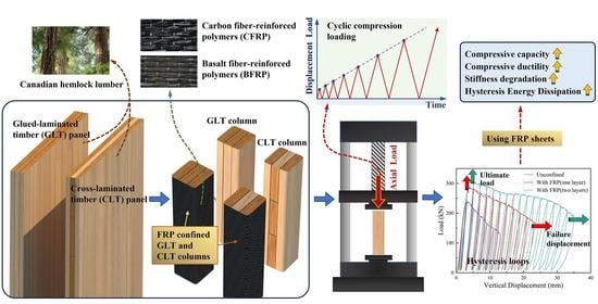
Axial Compression Behavior of FRP Confined Laminated Timber Columns under Cyclic Loadings

1
College of Civil Engineering, Nanjing Forestry University, Nanjing 210037, China
2
Jiangsu Engineering Co., Ltd. of China Railway 24th Bureau Group, Nanjing 210038, China
3
Housing and Real Estate Promotion Center, Jiangsu Provincial Department of Housing and Urban-Rural Development, Nanjing 210008, China
*
Author to whom correspondence should be addressed.
Buildings 2022, 12(11), 1841; https://doi.org/10.3390/buildings12111841
Submission received: 8 October 2022 / Revised: 24 October 2022 / Accepted: 31 October 2022 / Published: 1 November 2022
(This article belongs to the Special Issue Engineered Wood and Bamboo Composites in Hybrid Buildings)

Abstract

:
Fiber reinforced polymer (FRP) has been proved to be effective to improve the structural strength and ductility for column structures. An experimental study was conducted to investigate the compressive performance of FRP confined glued-laminated timber (GLT) and cross-laminated timber (CLT) columns. A total of 60 column specimens of two dimensions in height using different FRP types, FRP thickness, and laminate types were tested under cyclic axial compression loads. This study focuses on the compressive capacity and ductility of the new FRP composited timber structure. For this purpose, a loading protocol was designed, including a force-dependent pre-load and an amplitude-increasing displacement-dependent cyclic compression load. The results showed that the ultimate compression load of specimens was considerably promoted by the FRP sheets. Wrapping FRP sheets led to an average improvement of 29% and 24% for the FRP confined CLT and GLT specimens, respectively, compared to the initial stiffness of unreinforced specimens. Using the FRP sheets, the energy dissipation capacity of CLT and GLT specimens was increased by 358% and 266%, respectively. In general, GLT specimens had a higher energy dissipation rate compared to the CLT specimens, while CLT specimens showed a better potential for sustained energy consumption if confined with sufficient FRP sheets.

Graphical Abstract

1. Introduction

Laminated timber is widely used in engineering structures, including residential structures and pedestrian bridges. The key drivers for the use of the engineered wood structural members are the high transportation efficiency, low carbon emissions, and the advantages from local manufacturers [1]. Additional value of lower value local timber materials can be utilized using standardized manufacture technologies [2,3]. Among the laminated timber products, glued-laminated timber (GLT) and cross-laminated timber (CLT) are typical ones. The laminates in GLT are glued in parallel according to the wood grain direction. CLT panels have at least three timber layers, and the adjacent layers are arranged orthogonally. Unlimited specification for engineered wood and bamboo materials can be composited into CLT [4], giving the potential to invent more composite structures. In recent years, CLT has been proved suitable for the floors and walls in building structures [5,6,7,8,9].
CLT exhibits a greater bidirectional performance benefited by the perpendicular combination of dimension lumber [10]. Ringhofer et al. [11] investigated the nail-holding performance of GLT and CLT and concluded that CLT had the better ductility. Pang and Jeong [12] compared the compressive resistance of the CLTs made of different laminate thicknesses and strength grades. Regarding the CLT and GLT structures, the majority of the studies comprised the behavior of the column-to-beam connection system. For instance, Pozza et al. [13] conducted monotonic and cyclic axial shear tests on the angle bracket connections for CLT structures. However, only a few studies focused on the compression performance of GLT and CLT columns. In fact, the uncertainties arising from geometrical parameters, wood species properties, and the adhesive bonding can introduce large deficiencies in laminated timber columns. Therefore, for reliable use in building structures, a comprehensive investigation of the capacity and ductility for CLT and GLT columns is mandatory. Moreover, the reinforcement of this structure should also be concerned.
In recent years, FRP composites have been widely applied in beam and column structures, providing a higher corrosion resistance. As a well-known composite structure, the FRP confined concrete column has been comprehensively studied via both experimental and numerical investigations, and the influences of the thickness of FRP, the fiber type of FRP, the wrapping method, and the cross-sectional dimensions have been investigated [14,15,16,17]. In addition, Jahami et al. [18] studied the strengthening effects of FRP for reinforced concrete beams. Zhang et al. [19] analyzed the axial compression behavior of concrete-filled FRP-steel composite tube columns. Thamboo et al. [20] investigated the axial capacity and ductility of FRP confined masonry columns. Li et al. [21] performed axial compression tests on FRP confined laminated bamboo lumber columns. For timber structures, Han [22] and Dong [23] investigated the compressive behavior of FRP reinforced timber columns. Siha et al. [24] strengthened ancient circular timber columns with near-surface mounted steel bars and carbon fiber-reinforced polymers (CFRP) strips. Zhang et al. [25] investigated the recovery effect provided by FRP sheets in longitudinally cracked timber columns. Kim et al. [26] strengthened ageing timber bridge piles using glass fiber-reinforced polymers (GFRP). When using five layers, the peak strength and ductility of the specimens were improved by 70% and 90%, respectively. Previous studies have demonstrated the significant potential of using FRP sheets as a strengthening method for wood structures. Therefore, it is of interest to investigate the compressive capacity and ductility of FRP confined GLT and CLT columns.
In a previous test performed on the column-to-beam connections of timber structures [27], a combination of the axial and lateral hydraulic actuator was used to simulate compression (or tension) and shear loads, respectively. As the experiment setup shown in [13,28], a monotonic load could be provided by the axial actuator and low reversed cyclic loads were set for the lateral direction. In most studies involving low reversed cyclic loads, both positive and negative displacement domains are included. Considering that the purpose of this study was to investigate the axial compressive performance of FRP confined CLT and GLT columns, merely positive displacements (compression load) were designed. The similar loading rule can be found in [19,20]. A force-controlled load was added to the test protocol as a pre-loading procedure. In order to simulate dead loads of a structure, the applied loads were maintained as compressive during the unloading process.
The present study aims to investigate the axial compression performance of CLT and GLT columns confined with FRP sheets. Basalt fiber-reinforced polymers (BFRP) and carbon fiber-reinforced polymers (CFRP) were used and compared. A total of sixty specimens were manufactured and tested using different FRP thicknesses, FRP types, and the dimensions in height. The hysteretic behavior of the specimens was calibrated by analyzing the unloading laws, re-loading laws, and degradation rules. The cyclic response was inferred from the hysteretic load-deformation behavior, including the hysteresis loop and backbone curves. Then, the stiffness degradation and hysteresis energy dissipation of the specimens were illustrated. The proposed study presents an investigation of applying FRP sheets to CLT and GLT columns to examine the compressive strength and ductility of the new composite structures, which may be useful for the application and repair of laminated timber columns used for buildings.

2. Materials and Methods

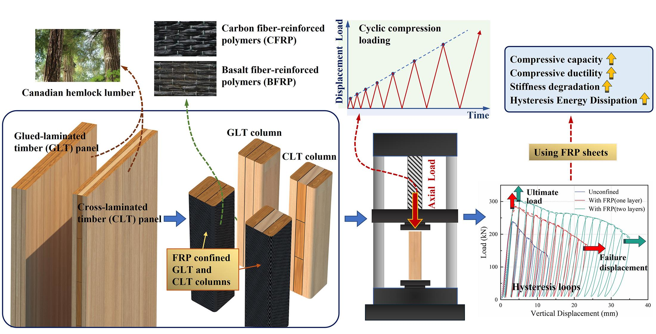
2.1. Specimen and Material Details

The bare GLT and CLT columns were manufactured at the pilot plant of the Ningbo Sino-Canada Low-Carbon Technology Research Institute. The GLT and CLT panels used in this study were composed of the Canadian hemlock lumber with an average density of 480 kg/m3 and a water content of 13.2%. The lumber was processed into pieces with a thickness of 35 mm, and then combined into GLT and CLT panels. Finally, the panels were cut into column specimens; see Figure 1. A single-component polyurethane was used to glue the lumber. The dimensional information of the CLT and GLT rounded rectangular columns is shown in Figure 1.
A total of 60 GLT and CLT column specimens were prepared. Twelve of these were specimens without FRP sheets, and the rest were confined with one or two FRP layers. The specimens shared the same number of FRP layers were divided into different groups based on the laminate type, FRP type, and the specimen dimension in height. The material properties of the FRP sheets are given in Table 1. For each column type, three specimens were prepared, detailed in Table 2. The cutting dimension for the length of the FRP sheets depended on the cross-sectional circumference of the column specimen. The front end of the FRP sheets was positioned at the longitudinal centerline of the column side face, see Figure 2, so that the end of the layer would not be located at the corner of the cross-section. To paste the sheet, the bicomponent epoxy resin was evenly applied on the FRP sheets after aligning the layer positions. The mechanical properties of the adhesive are listed in Table 1. The layers were then rolled onto the column and extruded by a scraper to remove the empty drum and excess adhesive. After being wrapped, the specimens were cured indoors for 14 days.

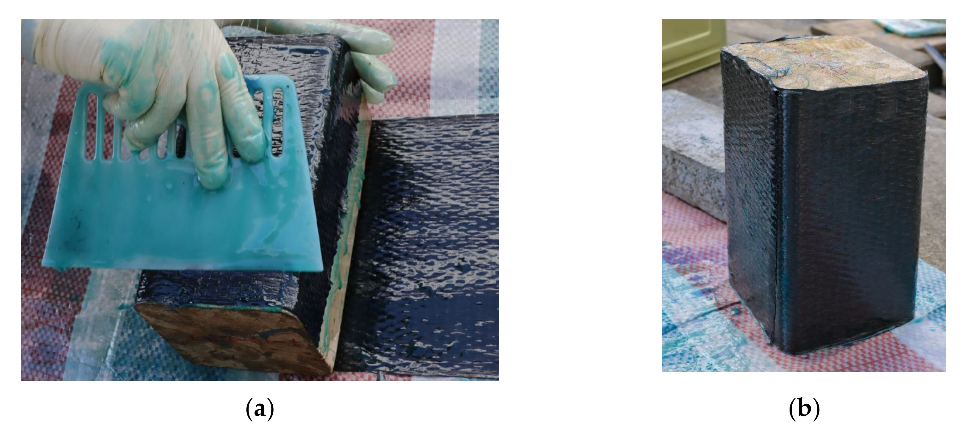
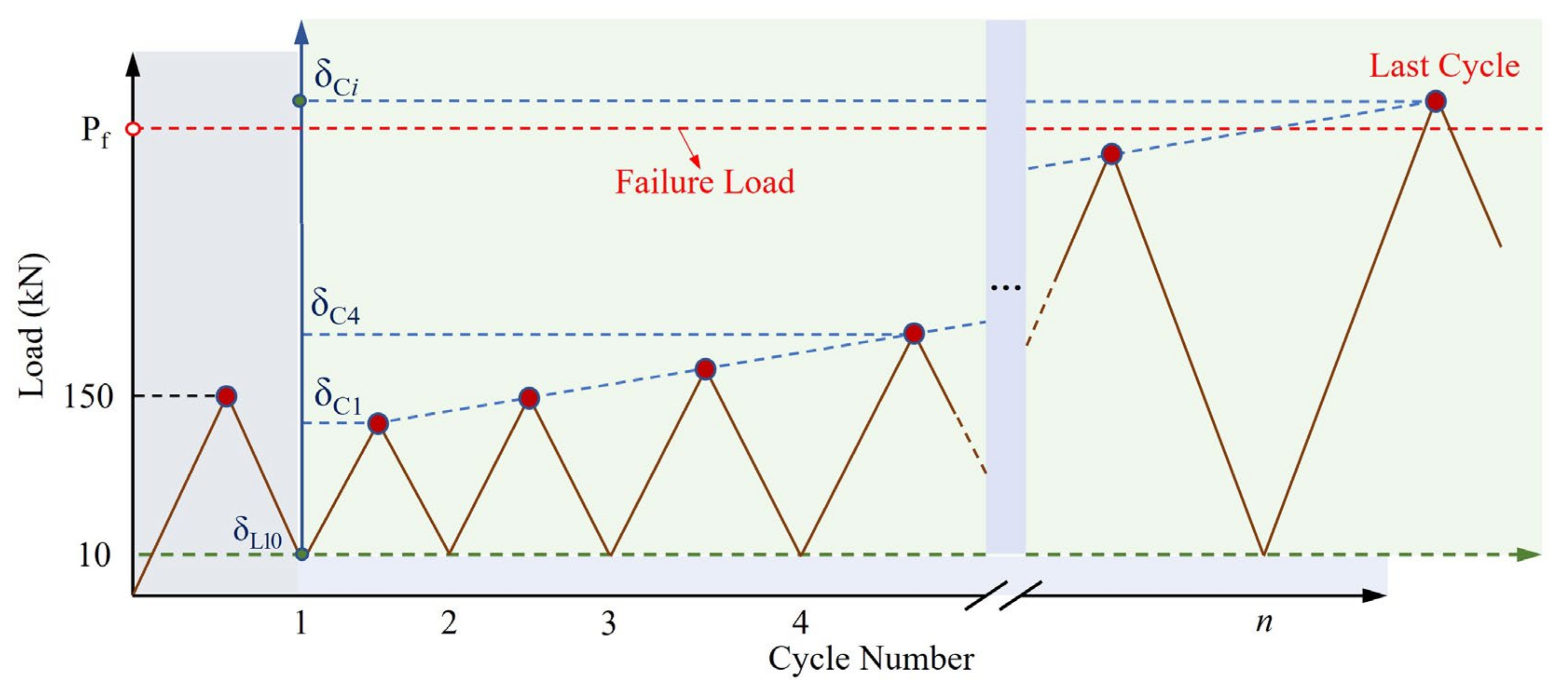
2.2. Test Setup and Loading Protocol

The column specimens were tested vertically using an electro-hydraulic servo universal test machine controlled by a microcomputer. The deformation was measured by two displacement meters, both measuring the relative displacement between the loading and the base plate. The end faces of the specimens were polished using sandpaper to reduce the end friction and improve the end flatness. The operating angle of the loading plate was adjusted to ensure axial compression on the specimen. The experimental tests were carried out at the Engineering Structure Laboratory of Nanjing Forestry University, and the test device is given in Figure 3.
The cyclic test consisted of a pre-loading procedure and a displacement-controlled cyclic compression loading rule, as shown in Figure 4. A monotonic test was performed as the pre-loading, with a load rate of 0.02 mm/s. As pointed by Wei et al. [29], to acquire the structure behavior in elastic stage, the compressive stress of each GLT and CLT specimen should be controlled under 60% of the ultimate strength. Note that the bare CLT specimens had an ultimate load of more than 220 kN, and the other specimens had much higher load capacities ranging from 263 kN to 459 kN. Hence, the pre-loading force was set to 150 kN, corresponding to 33–57% of the ultimate load for all specimens except the bare CLT ones. After the compressive force reached 150 kN, the force was reduced to 10 kN at an unloading rate of 0.02 mm/s. Then, the cyclic loads were applied using the same rate for the unloading and reloading process. To study the compression performance of GLT and CLT columns, only positive cyclic displacements were considered. Inspired by the reversed cyclic protocol proposed in FEMA461 [30], amplitude-increasing load steps with a linear displacement increasing rate were designed. For the first cycle in the protocol, the amplitude δC1 was determined as 3 mm. Then, the displacement of the following cycle increased by 2 mm so that amplitude δCi of the step i was given by Equation (1):
δCi = 2i + 1
The cycle number of the protocol was determined by the post-peak resistance load Pf, where Pf is defined as the failure load and estimated from the monotonic test on the same batch of the specimens by Equation (2):
Pf = 0.6 Pu
where Pu is the ultimate load of the specimen tested by a monotonic load protocol.

3. Results

3.1. Failure Modes

The typical failure behaviors of unreinforced specimens are given in Figure 5. For the specimens without FRP sheets, the crack failure in the adhesive joint face was the most typical failure mode. It was noticed that the laminates were held together at the end faces of the columns by the end friction, but separated apart along the longitudinal cracks. For CLT specimens, the width of the cracks was up to 12 mm, and the vertical length of the cracks could be close to the column height. Under the cyclic load, the connecting strength of the inter laminates was greatly dissipated, and the columns were split into two parts, as shown in Figure 5a. By looking at the narrow faces, the longitudinal laminates were crushed by local bending failure due to cross-sectional degradation. However, the side faces of the CLT specimens were relatively undamaged. However, for GLT specimens, see Figure 5b, more serious damages could be found from the side faces, which indicated that the vertical load sharing of GLT was more homogeneous.
After reinforcing the columns with FRP sheets, the failure modes of the specimens changed significantly, see Figure 6. The mode mainly included timber crushing failure, FRP cracking failure, and longitudinal buckling failure. All three modes could be observed from the 200 mm high FRP confining columns. As presented in Figure 6a,d, the timber crushing failure tended to occur at the top or bottom of a specimen. It could be inferred from the specimen integrity that the column had been reinforced by FRP, so that the timber material failure happened instead of a laminate separation failure. The longitudinal buckling failure could be identified from the narrow face of specimens where a bending or twist column shape was observed, see Figure 6b,e. For FRP cracking failure, see Figure 6c, a vertical FRP crack could be observed. For columns 400 mm high, the BFRP confined specimens tended to fail for the local timber crushing failure. In addition, the CFRP specimens were mainly crushed by the longitudinal buckling failure.

3.2. Monotonic Test Results

The monotonic test was performed using the same test setup as the cyclic test, and the loading rate for the monotonic test was set to 2 mm/min. The testing results for Pu are listed in Table 3. The ultimate strength σu was calculated by Equation (3):
σ u = P u A
where A is the cross-sectional area.
Compared to the unreinforced column specimens, the tested Pu of FRP-confined specimens was increased by 6.35% to 36.19%. For the parameter in similar studies, an increasing ratio of 10% and 27% was reported for laminated bamboo lumber columns [21] and timber columns [24], respectively. However, the increasing ratios for concrete columns [31] and CFST columns [19] were 93% and 84%, respectively. Although the strengthening ratio of the CLT and GLT columns was lower than that of the concrete specimens, the results were satisfactory when compared to the laminated bamboo lumber columns and timber columns.
It could be concluded that σu increased with the number of FRP layers. However, it was not clear whether the second FRP layer could provide more reinforcement than the first layer. For most cases, the additional enhancement of σu provided by the second FRP layer tended to decrease. However, for some specimens (i.e., G200B2 and C200C2), the second FRP still presented a relatively effective strengthening effect. For GLT specimens, the CFRP sheet provided more improvement for σu compared to BFRP sheets. When one FRP layer was used, the CFRP presented an advantage of 11% and 6% in uplifting the σu for C200 and G200 specimens, respectively. However, for the CLT specimens, the strengthening effects of CFRP and BFRP were similar. Some BFRP confined CLT specimens (i.e., C200B1 and C400B2) exhibited higher σu than the corresponding CFRP confined ones. Although the 400 mm-high specimens presented an average σu that was 4% lower than specimens with a height of 200 mm, the column height showed little influence on the testing results.
Moreover, for the CLT specimens, the standard deviation of Pu increased under the confinement of the FRP. The underlying reasons for this can be listed as follows. On the one hand, the FRP confined columns exhibited complex failure modes compared to the bare CLT and GLT specimens, increasing the deviation between the specimens. On the other hand, fabrication errors could uplift the standard deviation. For instance, torsion of the FRP sheets might occur during the winding process, and in addition, uneven usage of the adhesive and empty drums between the FRP sheets and the timber might also increase the standard deviation. In this work, the testing results of Pu were then used to determine the failure state for cyclic tests.

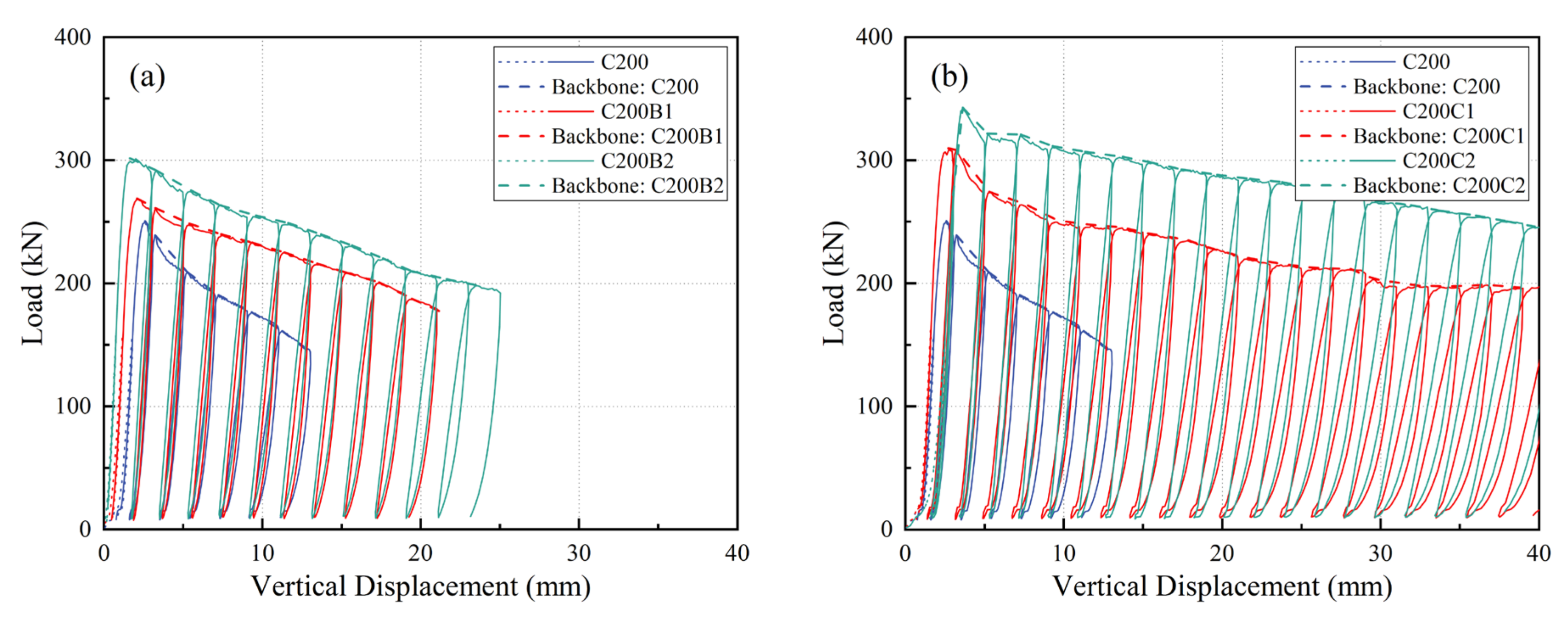
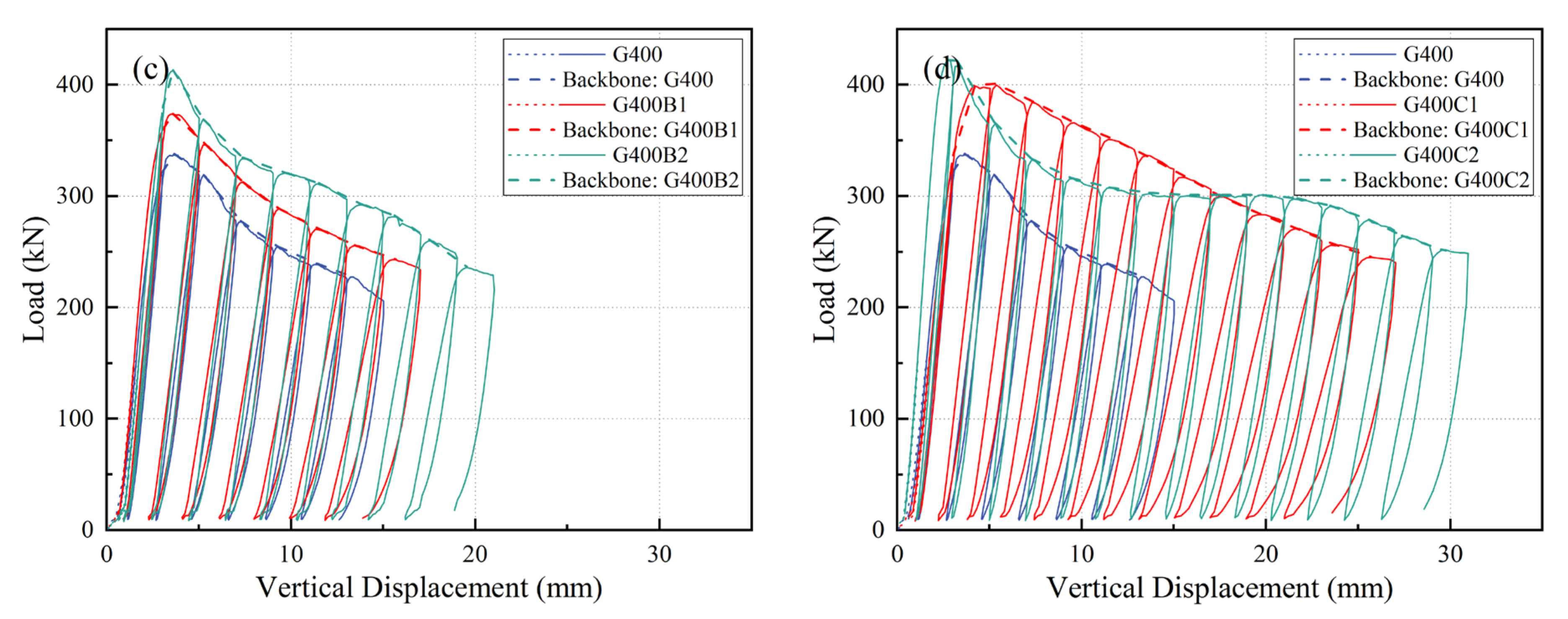
3.3. Cyclic Response

The cyclic compressive response of the specimens is described by hysteresis loops and backbone curves, which are shown in Figure 7, Figure 8 and Figure 9. The backbone curves are formed by connecting the peak points of the resulting experimental load–displacement curves. These curves describe the downward tendency of the ultimate load per cycle, demonstrating that the peak performance and degradation behavior of the compression capacity of the specimens were considerably improved by the FRP sheets. The pre-loading protocol for each specimen is plotted as a dashed line, and the cyclic protocol is painted by a solid line. The dashed lines almost coincide with the solid ones, proving that the preloading process was approximately conducted in the elastic stage of the specimen. From the cyclic test, see Figure 7, the bare GLT and CLT specimens presented similar intensity degradation trends, and the actual number of cycles in those specimens was close. The backbone curves highlight the fact that the ultimate cyclic load (Pu-cyc) occurs in the first or the second cycle, corresponding to a vertical displacement smaller than 5 mm. The compressive capacity decreased rapidly for the first two cycles and continuously degraded until reaching the Pf in the sixth or the seventh cycle.
For C200 specimens tested by the cyclic tests, as presented in Figure 8a, the Pu-cyc of CLT columns were increased by 4% and 15% when the single and double BFRP layers were utilized, respectively. The Pu-cyc of C200C2 and C200C1 specimens were 37% and 24% higher than that of C200, see Figure 8b. The strengthening performance of using CFRP was much better than that of BFRP. Moreover, for the C200 specimens, the second FRP layer resulted in an additional increasing ratio of more than 11%. However, for C400 specimens, see Figure 8c,d, limited reinforcement for Pu-cyc was presented using two FRP layers; in addition, the effects of using CFRP and BFRP were close. As shown in Figure 9a,b, for G200 specimens, the number of FRP layers had little influence on the Pu-cyc. The C200C1 and C200C2 specimens had a 4% lower strengthening ratio for Pu-cyc than the C200B1 and C200B2. Overall, CLT specimens had a better compression capacity enhancement potential than GLT specimens. For the G400C2 specimen, see Figure 9d, the Pu-cyc and the initial stiffness was improved compared to the G400C1, but the vertical displacement related to the ultimate load was much lower. Then, the G400C2 exhibited a greater load decreasing rate and resulted in a lower load capacity than the G400C1, suggesting a potential damage. However, when the vertical displacement exceeded 10 mm, the load-decreasing rate decreased and the load remained at about 300 kN. Hence, it is noted that the double-layers FRP prolonged the post-peak capacity degradation for the specimen.
The ductility of the specimens could be evaluated by comparing the cycle numbers determined from the calculated Pu. As shown in Figure 8 and Figure 9, the hysteresis loops demonstrate the fact that FRP confined specimens presented a better energy dissipation performance than those without FRP sheets. It can be observed that the FRP type was the key factor affecting the number of cycles. Compared to BFRP, the CFRP confined specimens performed considerably better. In addition, the number of FRP layers had a significant effect on the number of cycles. After the BFRP sheets were used, at least one more cycle was formed for the cyclic test. After using the CFRP sheets, at least two additional cycles were found in the load–displacement curves. However, it seems that the laminate type did not have a significant correlation with the cycle numbers. Using the BFRP sheet, the failure displacements of the CLT and GLT columns were increased by more than 14% and 39%, respectively. The average ultimate displacement of CLT and GLT specimens with two CFRP layers were 32.5 mm and 29.2 mm, respectively. On average, this represented an increase of 148% and 153% compared to unconfined specimens.

4. Discussion

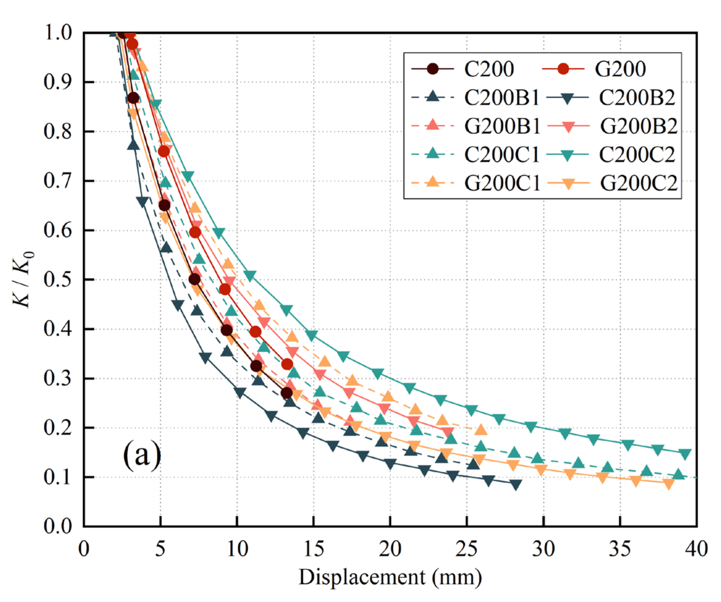
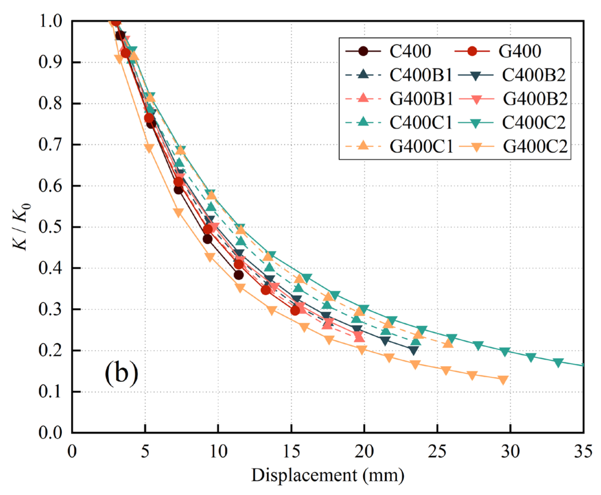
4.1. Stiffness Degradation Analysis

Table 4 presents the average initial compressive stiffness (K0) evaluated from the first cycle of the displacement-dependent cyclic load. For FRP confined CLT and GLT column specimens, wrapping the FRP sheets resulted in an average improvement of 29% and 24% in K0, respectively, compared to specimens without FRP. For specimens, G200B2, G400B2, and G400C2, using two FRP layers resulted in an average increasing ratio of 2%, 2%, and 15%, respectively, compared to the specimens confined with one layer. However, for the other two-layer confined specimens, the second FRP layer did not increase the K0. Considering that the coefficient of variation of the test results for a specimen type could increase up to 21% (C400C2), utilizing different FRP types or applying different numbers of FRP layer did not have a significant effect on the K0 of CLT and GLT columns. In addition, for confined specimens, the specimen height had an obvious effect on K0. The average K0 of FRP confined G200 specimens was 14% higher than that of G400 specimens.
Stiffness degradation curves with respect to the degradation ratio (K/K0) are compared in Figure 10, where K is the actual stiffness evaluated from hysteresis loops. From the results, it is noted that the correlation between K/K0 and FRP enhancement is not clear. Curves for unconfined specimens present a fair performance in the degradation ratio compared to some FRP reinforced specimens (i.e., C200B1, C200B2, G400C2). However, when the compression failure occurred, specimens confined with two FRP layers tended to present a lower degradation ratio than the other specimens. The degradation ratio is defined as Kf/K0, where Kf is the failure stiffness. It can be concluded that the FRP confined specimens had a lower Kf/K0 than the unconfined specimens. Moreover, for the G200, G400, and C400 specimens, CFRP presented a better effect than BFRP in reducing the Kf/K0. As revealed in Table 4, the C200C2, G200C2, C400C2, and G400C2 exhibited excellent Kf/K0 properties, illustrating that wrapping CLT and GLT specimens with two layers of CFRP sheets improved the ductility considerably.
To analyze the difference of the Kf/K0 between the bare column specimen and the confined specimen, the relatively change ratio of the Kf/K0 is introduced, and is defined as k, see Equation (4):
k = K f - con   K 0 - unc K 0 - con   K f - unc
where Kf-unc is the failure stiffness of the unconfined specimen, Kf-con is the failure stiffness of the confined specimen, K0-unc is the initial stiffness of the unconfined specimen, and K0-con is the initial stiffness of the FRP confined specimen.
For most specimen types, k decreased as the number of FRP layers increased. The application of CFRP sheets to the G200, G400, and C400 specimens resulted in more reinforcement compared to the application of BFRP. Compared to the G200 and C200 specimens, the FRP confined G400 and C400 specimens had a k both increased by an average of 31%. Thus, the column height might have an effect on k.

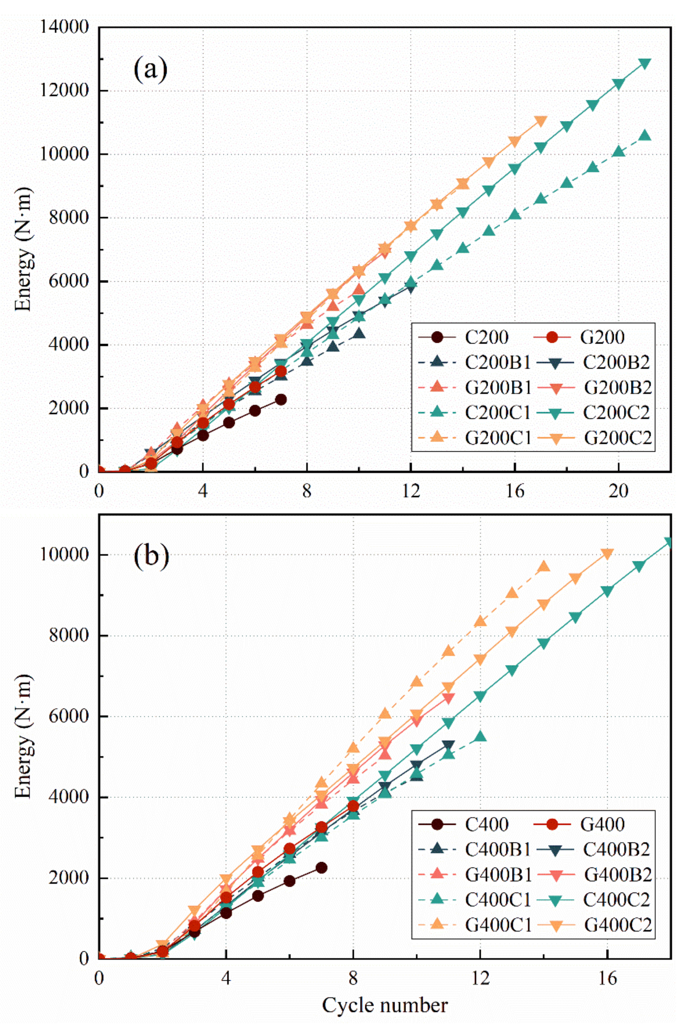
4.2. Characterization of Hysteresis Energy Dissipation

The hysteresis energy dissipation in the cyclic test can be evaluated by computing the enclosed area of the hysteresis loop. Figure 11 shows the cumulant curves of the hysteresis energy dissipation. In the case of the displacement-dependent load, the evolution of the cumulated energy dissipation presented an approximately linearly increasing trend up to failure. It could be concluded that the GLT specimen had a higher energy dissipation rate than the CLT specimen by comparing the slope of those curves. This means that, when a specific axial displacement load was applied, the GLT column consumed more energy compared to the CLT column. The curves highlight that the energy dissipation properties of the CLT and CLT specimens are greatly improved by the FRP sheets. For specimens 400 mm high, C400B1 and C400B2 showed an improvement of 99% and 135% in dissipation compared to the C400, respectively. In addition, the dissipation was multiplied by 2.42 and 4.58 times for the C400C1 and C400C2, respectively. Dissipation was increased by a factor of 2.33, 2.71, 3.56, and 3.66 for specimens G400B1, G400B2, G400C1, and G400C2, respectively, compared to the G400. Moreover, the results showed that CFRP sheets provided a larger improvement in the energy consumption performance compared to the BFRP sheets. In addition, specimens confined with two FRP layers exhibited better cumulative energy consumption performance than those confined with a single layer. However, the correlation between the energy dissipation rate and the number of FRP layers was not significant, especially for the GLT column.

4.3. Recommendations

The recommendations according to the conducted research studies are as follows:
  • The fabrication of the FRP confined laminated timber columns must be standardized. This is because the manufacture factors, including the initial defects for the timber materials, the cutting and processing rules for structural components, and FRP warping methods, have a great effect on the testing results.
  • The FRP sheets can be punctured by the crushed timber. This is because the curved FRP layer (using epoxy resin) has a poor bending and vertical tensile strength. The investigation of appropriate solutions to this problem is required.
  • There is a need to test full-scale structural CLT and GLT members confined with FRP sheets subjected to monotonic and cyclic loads, so that the structural buckling failure can be investigated beyond the material failure modes.

5. Conclusions

In this work, the compressive behavior of CLT and GLT columns was investigated using monodirectional cyclic loads. The effects of the FRP type, FRP thickness, and laminated column type were involved. The specimen groups were designed with a height of 200 mm and 400 mm, and a total of sixty specimens were manufactured. Compared to the test results from the monotonic tests, cyclic response of twenty kinds of specimens was characterized by analyzing the hysteresis loops curves. The conclusions can be drawn as follows:
  • For CLT columns without FRP sheets, the crack failure of the adhesive joint face was the most typical mode. For unreinforced GLT columns, specimens were damaged by adhesive joint failure combined with laminate cracking failure. Three failure modes were identified in FRP confined specimens, which included timber crushing failure, FRP cracking failure, and longitudinal buckling failure
  • The backbone curves demonstrated that the ultimate compression load capacity of specimens was considerably increased by FRP sheets. It can be found that the CFRP sheet has a larger reinforcement effect than the BFRP sheet. Moreover, CLT specimens have a better potential for compressive capacity reinforcement compared to GLT specimens.
  • Compared to unreinforced specimens, wrapping FRP sheets led to an average improvement of 29% and 24%, respectively, in initial stiffness for FRP confined CLT and GLT column specimens. However, using different FRP types or applying different numbers of FRP layers did not have a significant effect on the stiffness of CLT and GLT columns.
  • GLT specimens had a higher energy dissipation rate compared to the CLT specimens. The energy dissipation properties of the CLT and GLT specimens were greatly improved by the FRP sheets. In particular, the energy was increased by 99–358%. Moreover, CFRP sheets provided more improvement in the energy consumption performance compared to BFRP sheets. Specimens confined with two FRP layers exhibited better cumulative energy consumption performance than those confined with a single FRP layer.

Author Contributions

Conceptualization, L.W. and H.L.; methodology, F.S.; software, F.S.; validation, L.W., H.D., and H.L.; formal analysis, F.S.; investigation, M.Z. and F.W.; resources, M.Z.; data curation, M.Z.; writing—original draft preparation, F.S.; writing—review and editing, H.D. and S.W.; visualization, F.S.; supervision, L.W.; project administration, L.W. and F.W.; funding acquisition, H.D. All authors have read and agreed to the published version of the manuscript.

Funding

This research was funded by the National Natural Science Foundation of China, Grant No. 52208257, and the Natural Science Foundation of Colleges and Universities of Jiangsu Province, Grant No. 22KJB1020221074.

Institutional Review Board Statement

Not applicable.

Informed Consent Statement

Not applicable.

Data Availability Statement

Not applicable.

Acknowledgments

The authors gratefully thank Xiang Ding, Qinchao Luo, Hao Ma, and Feng Zhang from Nanjing Forestry University for the assistance in experiments.

Conflicts of Interest

The authors declare no conflict of interest.

References

  1. Zaman, A.; Chan, Y.Q.; Jonescu, E.; Stewart, I. Critical Challenges and Potential for Widespread Adoption of Mass Timber Construction in Australia—An Analysis of Industry Perceptions. Buildings 2022, 12, 1405. [Google Scholar] [CrossRef]
  2. Fleming, P.H.; Ramage, M.H. Full-scale construction and testing of stress-laminated columns made with low-grade wood. Constr. Build. Mater. 2020, 230, 116952. [Google Scholar] [CrossRef]
  3. Liew, K.C.; Tan, Y.F.; Albert, C.M.; Raman, V. Cross-Laminated Timber and Glulam from Low-Density Paraserianthes falcataria: A Look into Densification and Shear Strength. Forests 2022, 13, 1540. [Google Scholar] [CrossRef]
  4. Li, H.; Wang, B.J.; Wang, L.; Wei, P.X.; Wei, Y.; Wang, P.Z. Characterizing engineering performance of bamboo-wood composite cross-laminated timber made from bamboo mat-curtain panel and hem-fir lumber. Compos. Struct. 2021, 266, 113785. [Google Scholar] [CrossRef]
  5. Hassan, O.; Berg, F.; Gezelius, E. Cross-laminated timber flooring and concrete slab flooring: A comparative study of structural design, economic and environmental consequences. J. Build. Eng. 2019, 26, 100881. [Google Scholar] [CrossRef]
  6. Sun, X.; He, M.; Li, Z. Experimental and Analytical Lateral Performance of Posttensioned CLT Shear Walls and Conventional CLT Shear Walls. J. Struct. Eng. 2020, 146, 04020091. [Google Scholar] [CrossRef]
  7. Oh, J.K.; Hong, J.P.; Kim, C.K.; Pang, S.J.; Lee, S.J.; Lee, J.J. Shear behavior of cross-laminated timber wall consisting of small panels. J. Wood Sci. 2017, 63, 45–55. [Google Scholar] [CrossRef] [Green Version]
  8. Thai, M.V.; Menard, S.; Elachachi, S.M.; Galimard, P. Performance of Notched Connectors for CLT-Concrete Composite Floors. Buildings 2020, 10, 122. [Google Scholar] [CrossRef]
  9. Blass, H.J.; Schadle, P. Ductility aspects of reinforced and non-reinforced timber joints. Eng. Struct. 2011, 33, 3018–3026. [Google Scholar] [CrossRef]
  10. Stenson, J.; Ishaq, S.L.; Laguerre, A.; Loia, A.; MacCrone, G.; Mugabo, I.; Northcutt, D.; Riggio, M.; Barbosa, A.; Gall, E.T.; et al. Monitored Indoor Environmental Quality of a Mass Timber Office Building: A Case Study. Buildings 2019, 9, 142. [Google Scholar] [CrossRef]
  11. Ringhofer, A.; Brandner, R.; Blass, H.J. Cross laminated timber (CLT): Design approaches for dowel-type fasteners and connections. Eng. Struct. 2018, 171, 849–861. [Google Scholar] [CrossRef]
  12. Pang, S.J.; Jeong, G.Y. Load sharing and weakest lamina effects on the compressive resistance of cross-laminated timber under in-plane loading. J. Wood Sci. 2018, 64, 538–550. [Google Scholar] [CrossRef] [Green Version]
  13. Pozza, L.; Saetta, A.; Savoia, M.; Talledo, D. Angle bracket connections for CLT structures: Experimental characterization and numerical modelling. Constr. Build. Mater. 2018, 191, 95–113. [Google Scholar] [CrossRef]
  14. Dai, J.G.; Bai, Y.L.; Teng, J.G. Behavior and modeling of concrete confined with FRP composites of large deformability. J. Compos. Constr. 2011, 15, 963–973. [Google Scholar] [CrossRef]
  15. Cui, C.; Sheikh, S.A. Experimental study of normal- and high-strength concrete confined with fiber-reinforced polymers. J. Compos. Constr. 2010, 14, 553–561. [Google Scholar] [CrossRef]
  16. Wei, Y.; Zhang, X.; Wu, G.; Zhou, Y.F. Behaviour of concrete confined by both steel spirals and fiber-reinforced polymer under axial load. Compos. Struct. 2018, 192, 577–591. [Google Scholar] [CrossRef]
  17. Khorramian, K.; Sadeghian, P. New mechanics-based confinement model and stress-strain relationship for analysis and design of concrete columns wrapped with FRP composites. Structures 2021, 33, 2659–2674. [Google Scholar] [CrossRef]
  18. Jahami, A.; Temsah, Y.; Khatib, J.; Baalbaki, O.; Kenai, S. The behavior of CFRP strengthened RC beams subjected to blast loading. Mag. Civ. Eng. 2021, 103, 10309. [Google Scholar] [CrossRef]
  19. Zhang, Y.; Wei, Y.; Zhao, K.; Ding, M.; Wang, L. Analytical model of concrete-filled FRP-steel composite tube columns under cyclic axial compression. Soil Dyn. Earthq. Eng. 2020, 139, 106414. [Google Scholar] [CrossRef]
  20. Thamboo, T.; Zahra, T.; Asad, M.; Silva, L.; Gimhani, J. Analytical model for CFRP confined masonry columns subjected to monotonic and cyclic compression. Comp. Struct. 2022, 292, 115696. [Google Scholar] [CrossRef]
  21. Li, H.; Li, H.T.; Hong, C.K.; Xiong, Z.H.; Lorenzo, R.; Corbi, I. Experimental investigation on axial compression behavior of laminated bamboo lumber short columns confined with CFRP. Compos. Part A-APPL S. 2021, 150, 106605. [Google Scholar] [CrossRef]
  22. Han, F.; Liu, Q.; Guo, X.; Zhang, M.; Han, X. Analytical study on axial and eccentric compressive behavior of poplar column strengthened by BFRP. Wood Res.-Slovak. 2022, 67, 11–25. [Google Scholar] [CrossRef]
  23. Dong, J.F.; Jia, P.; Yuan, S.C.; Wang, Q.Y. Compressive behaviours of square timber columns reinforced by partial wrapping of FRP sheets. Mater. Res. Innov. 2015, 19, S465–S468. [Google Scholar] [CrossRef]
  24. Siha, A.; Zhou, C.D.; Yang, L.G. Experimental Study on Axial Compression Behavior on Circular Timber Columns Strengthened with CFRP Strips and Near-Surface Mounted Steel Bars. J. Struct. Eng. 2021, 147, 04021003. [Google Scholar]
  25. Zhang, W.P.; Song, X.B.; Gu, X.L.; Tang, H.Y. Compressive Behavior of Longitudinally Cracked Timber Columns Retrofitted Using FRP Sheets. J. Struct. Eng. 2012, 138, 90–98. [Google Scholar] [CrossRef]
  26. Kim, K.H.E.; Andrawes, B. Compression behavior of FRP strengthened bridge timber piles subjected to accelerated aging. Constr. Build. Mater. 2016, 124, 177–185. [Google Scholar] [CrossRef]
  27. Santarsiero, G. FE Modelling of the Seismic Behavior of Wide Beam-Column Joints Strengthened with CFRP Systems. Buildings 2018, 8, 31. [Google Scholar] [CrossRef] [Green Version]
  28. Franco, L.; Pozza, L.; Saetta, A.; Savoia, M.; Talledo, D. Strategies for structural modelling of CLT panels under cyclic loading conditions. Eng. Struct. 2019, 198, 109476. [Google Scholar] [CrossRef]
  29. Wei, P.; Wang, B.J.; Li, H.; Wang, L.; Peng, S.; Zhang, L. A comparative study of compression behaviors of cross-laminated timber and glued-laminated timber columns. Constr. Build. Mater. 2019, 222, 86–95. [Google Scholar] [CrossRef]
  30. Federal Emergency Management Agency. Interim Testing Protocols for Determining the Seismic Performance Characteristics of Structural and Nonstructural Components; Federal Emergency Management Agency: Washington, DC, USA, 2007; pp. 13–26.
  31. Lam, L.; Teng, J.G. Ultimate condition of fiber reinforced polymer-confined concrete. J. Compos. Constr. 2004, 8, 539–548. [Google Scholar] [CrossRef]
Figure 1. Diagram of GLT and CLT column specimens: (a) laminate combination; (b) dimensional parameters (dimensions in mm).
Buildings 12 01841 g001
Figure 2. Specimen preparation: (a) wrapping the specimen with FRP sheets; (b) completed specimen.
Buildings 12 01841 g002
Figure 3. Diagram of the test setup.
Buildings 12 01841 g003
Figure 4. Cyclic loading protocol.
Buildings 12 01841 g004
Figure 5. Typical failure modes of unconfined specimens: (a) C400-2; (b) G400-3.
Buildings 12 01841 g005
Figure 6. Typical failure modes of specimens: (a) C200C1-2; (b) C200C2-1; (c) G200B1-3; (d) G400B1-1; (e) G400C2-2.
Buildings 12 01841 g006
Figure 7. Cyclic responses of unreinforced CLT and GLT columns: (a) C200 and G200; (b) C400 and G400.
Buildings 12 01841 g007
Figure 8. Hysteresis loops and backbone curves of FRP confined CLT columns: (a) BFRP confined C200 specimens; (b) CFRP confined C200 specimens; (c) BFRP confined C400 specimens; (d) CFRP confined C400 specimens.
Buildings 12 01841 g008aBuildings 12 01841 g008b
Figure 9. Hysteresis loops and backbone curves of FRP confined GLT columns: (a) BFRP confined G200 specimens; (b) CFRP confined G200 specimens; (c) BFRP confined G400 specimens; (d) CFRP confined G400 specimens.
Buildings 12 01841 g009aBuildings 12 01841 g009b
Figure 10. Stiffness degradation ratio: (a) Specimens 200 mm high; (b) Specimens 400 mm high.
Buildings 12 01841 g010aBuildings 12 01841 g010b
Figure 11. Cumulation of hysteresis energy dissipation: (a) Specimens 200 mm high; (b) Specimens 400 mm high.
Buildings 12 01841 g011
Table 1. Properties of FRP and epoxy resins.
Title 1Modulus of Elasticity
(GPa)
Ultimate Tensile Strength
(MPa)
Ultimate Strain
(mm/mm)
AverageStandard
Deviation
AverageStandard
Deviation
AverageStandard
Deviation
CFRP
BFRP
Epoxy resin
227.96.93765.0421.70.0190.002
75.83.01706.6205.50.0240.002
2.90.267.75.40.0290.001
Table 2. Details of test specimens.
Specimen GroupsNumber of SpecimensLaminate TypeFRP TypeNumber of
FRP Layers
Specimen Height
(mm)
FRP Thickness
(mm)
Average Cross-Sectional Area
(mm2)
G2003GLT20011,048.3
G40040011,078.9
G200B1BFRP12000.15111,115.1
G200B2BFRP22000.30211,176.9
G200C1CFRP12000.16711,080.6
G200C2CFRP22000.33411,133.1
G400B1BFRP14000.15111,169.4
G400B2BFRP24000.30211,180.3
G400C1CFRP14000.16711,124.3
G400C2CFRP24000.33411,160.6
C2003CLT20010,996.7
C40040010,987.7
C200B1BFRP12000.15111,057.5
C200B2BFRP22000.30211,141.2
C200C1CFRP12000.16711,036.5
C200C2CFRP22000.33411,106.7
C400B1BFRP14000.15111,064.0
C400B2BFRP24000.30211,141.7
C400C1CFRP14000.16711,066.4
C400C2CFRP24000.33411,143.6
Table 3. Average ultimate load tested in the monotonic test.
Specimen TypePu (kN)Average Cross-Sectional Area (mm2)σu (MPa)
AverageStandard Deviation
G200355.811.311,028.732.3
G200B1378.413.011,178.033.9
G200B2410.59.811,261.336.5
G200C1412.019.511,014.637.4
G200C2429.729.011,187.838.4
G400346.725.211,081.231.3
G400B1375.311.411,233.933.4
G400B2390.422.511,140.335.0
G400C1393.615.611,179.235.2
G400C2410.421.611,340.636.2
C200251.99.711,063.522.8
C200B1297.714.611,107.926.8
C200B2322.817.111,106.729.1
C200C1292.812.311,040.626.5
C200C2324.821.611,093.829.3
C400231.912.810,990.821.1
C400B1283.713.611,013.825.8
C400B2315.814.211,055.728.6
C400C1298.620.611,045.427.0
C400C2309.418.211,127.927.8
Table 4. Initial stiffness in the cyclic test.
Specimen TypeK0 (kN/mm)Kf/K0k
AverageStandard Deviation
G200109.26.00.33
G200B1137.617.00.210.65
G200B2140.515.80.190.59
G200C1148.49.80.190.59
G200C2147.713.70.090.27
G400108.52.50.30
G400B1122.49.70.230.77
G400B2124.74.90.240.81
G400C1120.06.30.210.72
G400C2138.37.80.130.44
C20080.314.10.27
C200B1109.34.90.120.46
C200B2108.415.50.090.32
C200C1105.29.20.100.36
C200C2101.910.30.150.55
C40076.25.90.38
C400B191.35.20.270.70
C400B289.44.20.200.53
C400C1100.714.00.220.57
C400C299.321.00.160.42
Publisher’s Note: MDPI stays neutral with regard to jurisdictional claims in published maps and institutional affiliations.

