Article

Bearing Behavior of Axially Compressed High-Strength Steel Columns in Precipitator Casing Considering the Stressed-Skin Effect of Wallboard

School of Environment and Civil Engineering, Jiangnan University, Wuxi 214122, China
*
Author to whom correspondence should be addressed.
Buildings 2022, 12(10), 1737; https://doi.org/10.3390/buildings12101737
Submission received: 23 September 2022 / Revised: 14 October 2022 / Accepted: 16 October 2022 / Published: 19 October 2022
(This article belongs to the Special Issue Advances in Steel Structures: Testing, Modelling and Design)

Abstract

:
To explore the application feasibility of high-strength steel in skeleton columns of precipitator casing structures, the bearing behavior of axially compressed H-section high-strength steel columns was investigated by the nonlinear finite element method by considering the stressed-skin effect of wallboard. When the column yield strength does not exceed 460 MPa, the column undergoes elasto-plastic interactive buckling, which means the steel strength can be fully utilized. For the column strength of 550 MPa or 690 MPa, the wallboard yield failure occurs, owing to excessive loading of the relatively weak wallboard, and column stress magnitude is usually in the elastic range without the full utilization of steel strength, whereas if the wallboard is stiff enough, columns will still undergo buckling failure. A welding residual stress measuring test was conducted to validate the residual stress generation simulation via the thermal-mechanical coupling finite element method. Concerning the geometrical imperfections and residual stresses, it was found that their influence becomes less severe when the column steel strength increases. The bearing capacity can be improved by increasing the wallboard thickness and stiffener stiffness, or reducing the wallboard width, the stiffener spacing, the width-to-thickness ratio of column flange, the height-to-thickness ratio of column web, and column torsional slenderness ratio. Column material can be fully utilized when column steel strength does not exceed 460 MPa. Hence, employing high-strength steel is reasonable. When the column steel strength is equal to or higher than 550 MPa, wallboard strength should be sufficient to ensure that the column failure occurs before wallboard failure. In such cases, high-strength steel should be used carefully.

1. Introduction

Precipitators are widely used to eliminate dust in the thermal power, metallurgy, building materials, and chemical industries, and therefore, they provide important protection from environmental pollutants. Typically, the research on precipitators is mainly focused on the dust collecting process, whereas few studies have been carried on the load resistance of precipitator supporting structures. This has led to a paucity of innovative research on the application of new structural materials and forms of precipitator supporting structures. This paper aims to investigate the use of high-strength steel in skeleton columns of precipitator casing, which is of reference significance to the structural design of high-strength steel supporting members in other box-type structures.
The casing where soot particles are collected is the most important technical component of a precipitator. The casing of medium-to-large-sized precipitators is often constructed from stiffened steel wallboards and H-section steel columns (shown in Figure 1). The wallboards and columns are connected by continuous welding to form a single structure within which the various components cooperatively resist loads. Wallboards mainly serve as an enclosure to withstand transverse loads caused by negative air pressure and wind loads. Columns act as a vertical skeleton to sustain transverse loads transferred by the wallboards, and the axial compression transferred by top beams. In this way, the columns are, in fact, beam-column members. Since stress and deformation of the columns caused by transverse loading are small, columns are mainly subjected to axial loading [1]. This knowledge forms the theoretical foundation for this research, and only axial compression is investigated in this paper.
A series of studies were previously carried out on the precipitator structure, which mainly focused on structural optimization. Rane et al. [2] optimized the sizes and arrangements of stiffeners for electrostatic precipitator cone structure. Ji et al. [3] produced an optimal design method based on a multi-objective mathematical optimization model composed of the minimum compliance, and the maximum natural frequency; meanwhile, the improved adaptive growth method for the stiffener layout achieved a lightweight design of the inlet structure. Based on the strength calculations for an entire electrostatic precipitator structure, Wang et al. [4] optimized the dimensions of the main frame structure using linear elastic finite element analyses. The majority of these studies optimized the dimensions and layout of precipitator components, whereas the application of high-strength steel for lightweight design has not been explored.
A few studies focused on the structural behavior of precipitator casings. Qian et al. [5] investigated the failure modes of wallboards in precipitator casing by considering the stressed-skin effect and conducted the extensive influence analyses of the structural parameters on the wallboard bearing capacity. Xu and Wang. [6] carried out the finite element analyses on the stability of axially compressed double-limb columns of precipitator casing and proposed an evaluation formula for buckling capacity. All the above studies found that the wallboard acting as the stressed skin influences the column bearing behavior by supporting some of the loads and providing lateral constraints for the column. Therefore, columns composed of normal strength steel (235 MPa) exhibit significantly improved stability compared to those working independently, and the material strength can be fully utilized. However, the existing design code of electrostatic precipitator in China [7] only specifies that the stressed-skin effect of the wallboards can be considered in the column design, but it does not provide the quantitative design formulas, let alone the high-strength steel application. Based on this premise and in light of the rapid development of research and engineering applications of high-strength steels, this paper explores the potential of applying high-strength steel for the construction of skeleton columns of precipitator casings.
High-strength steels are widely used in construction to reduce the weight of structures. The stability of columns under axial compression has been investigated by both experimental and numerical methods. To this end, various design recommendations have been proposed for columns made of steel with various strengths (460 MPa to 960 MPa), dimensions, and sections (e.g., the H-section and box-section) [8,9,10,11,12,13,14,15]. For axially compressed high-strength steel columns, the influence of initial imperfections was found to decrease, and overall buckling factor was significantly increased; therefore, improved column curves can be selected. For high-strength steel beams with web openings, the effects of sectional sizes, opening diameters, opening numbers, and load types on the bearing capacity were numerically investigated, and a modified design equation based on the existing design rules was proposed [16]. Under eccentric compression, the buckling behavior of welded H-section and box-section columns made of high-strength steel (460 MPa to 960 Mpa) were investigated, both experimentally and numerically, and the influence of structural parameters and eccentricity were analyzed [17,18,19]. Both studies concluded that current design codes underestimate the bearing capacity for the high-strength steel columns and provide conservative evaluations.
At present, research on high-strength steel structural systems is lacking. Only seismic responses of high-strength steel frames have been reported. To this end, Hu et al. [20,21] conducted cyclic loading experiments of high-strength steel frames (460 MPa and 890 MPa), and investigated the global response at the frame level and the local response of members, respectively. Lian et al. [22] and Tian et al. [23] studied the seismic performance of eccentrically braced Y-shaped and K-shaped high-strength steel frame structures based on experiment and the finite element approaches. It was found that when effectively used in frames, high-strength steel can improve the seismic performance of structural systems, thereby reducing steel consumption. Previous research has mainly been concerned with component-level design, whereas almost no published research reports are available on high-strength steel members supported by stressed-skin wallboards to fully utilize the advantages of high-strength steels.
In this paper, the stressed-skin effect of the wallboard was fully considered and the nonlinear finite element method was used to examine the axial bearing behavior of steel columns with yield strengths ranging from 235 MPa to 690 MPa. Further, the use of high-strength steel in precipitators was analyzed, aiming to provide a fundamental theoretical basis for future engineering applications. It is important to note that wallboards are mainly subjected to transverse loads which cause the low stress levels. Therefore, wallboards can be made of normal-strength steel (235 MPa) and their design should be based on the stiffness or deformation conditions of the particular application.

2. Research Model

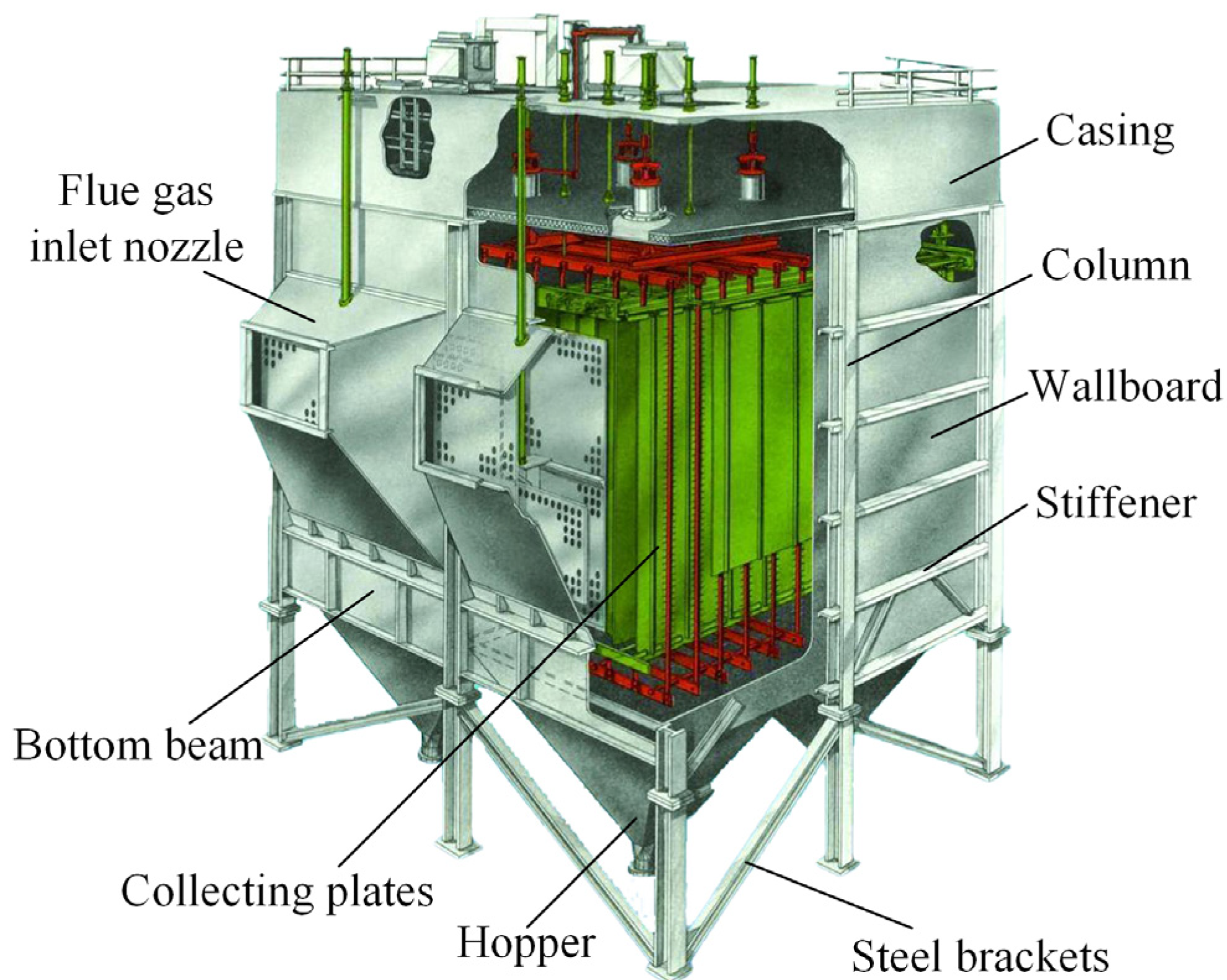
2.1. Structural Model

Based on the configuration of the precipitator casing in practical engineering applications, six basic research models were designed. Specific geometric parameters are listed in Table 1. The models cover geometries ranging from small to large-scale precipitators; therefore, the results provide a general reference and offer wide-ranging significance. To simplify the model and improve computational efficiency, only double-span wallboards were considered, which differ from actual multi-span wallboard structures. Bearing behavior of the middle column was examined. A schematic illustration of the structural system is presented in Figure 2.
The flange of the column welded to the wallboard is defined as the rear flange and the flange away from the wallboard is defined as the front flange. The wallboard has width w and thickness t, and spacing between angle stiffeners on the wallboard is s. The total height of the column is H. To reduce the column slenderness, equally spaced transverse braces are placed in horizontal direction (Y-direction) inside the casing, thereby providing constraints perpendicular to the wallboard. Spacing between the transverse braces is l. The stiffened beam is set at the bottom of the wallboard and connected to the ash hopper.

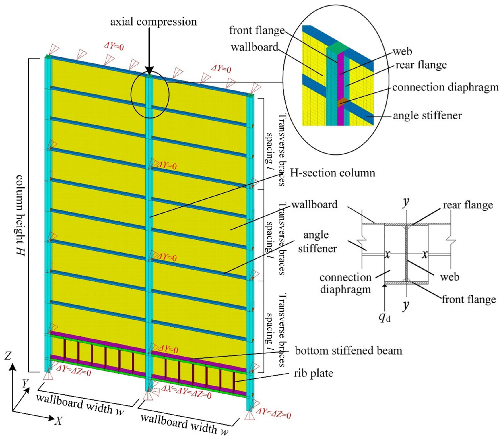
2.2. Finite Element Model

In this paper, the wall–column structure system of the precipitator casing was simulated using the general finite element code package ANSYS. The SHELL181 element was selected to model all structural components. The top and the bottom of the wallboard are connected to the stiffened top roof and the stiffened ash hopper plate, respectively. To simulate this, translational constraints perpendicular to wallboards (in Y-direction) were applied to the top and bottom boundaries. Columns were arranged with equally spaced transverse braces, which were simulated by applying translational constraints perpendicular to the wallboards. Translational constraints were applied at the bottom of the middle column in three directions. Since the temperature of the smoke inside the casing is varying, the bottom of the two side columns were translationally constrained in both the Y and Z directions, whereas the constraint in X direction was released to freely realize the temperature deformation in wallboard plane.
The mesh convergence tests were conducted to ensure that the mesh size could guarantee the computation accuracy. The number of column meshes was no less than 6 in the flange width direction and no less than 8 in the web height direction, and the height-to-width ratio of meshes did not exceed 2. The width of the wallboard meshes did not exceed 120 mm and the height did not exceed 50 mm. The refined meshing details of the column top region with complex configuration are shown in Figure 2.
The top of the column sustains the weight of the equipment on the roof and the ash load transferred by the top supporting beam. Therefore, axial compression was applied on the rigid cover at the top of the middle column until the ultimate load Ncr was reached. The nominal axially compressed buckling factor, φ = Ncr/Ny, of the column was defined to evaluate the stability of the column and reflect its nominal stress magnitude when the structure failed. Herein, Ny is the yield compression for a full H-section, Ny = AHfy, where AH is the column section area and fy is the column steel yield strength. Since the stiffened wallboards support part of load for the column, the area actually sustaining the top load must exceed AH, such that the ultimate load will be greater than the full section yield load; in this case, φ is possibly greater than 1.

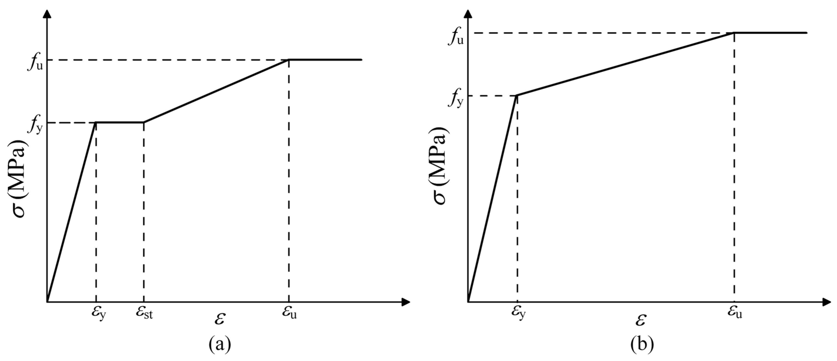
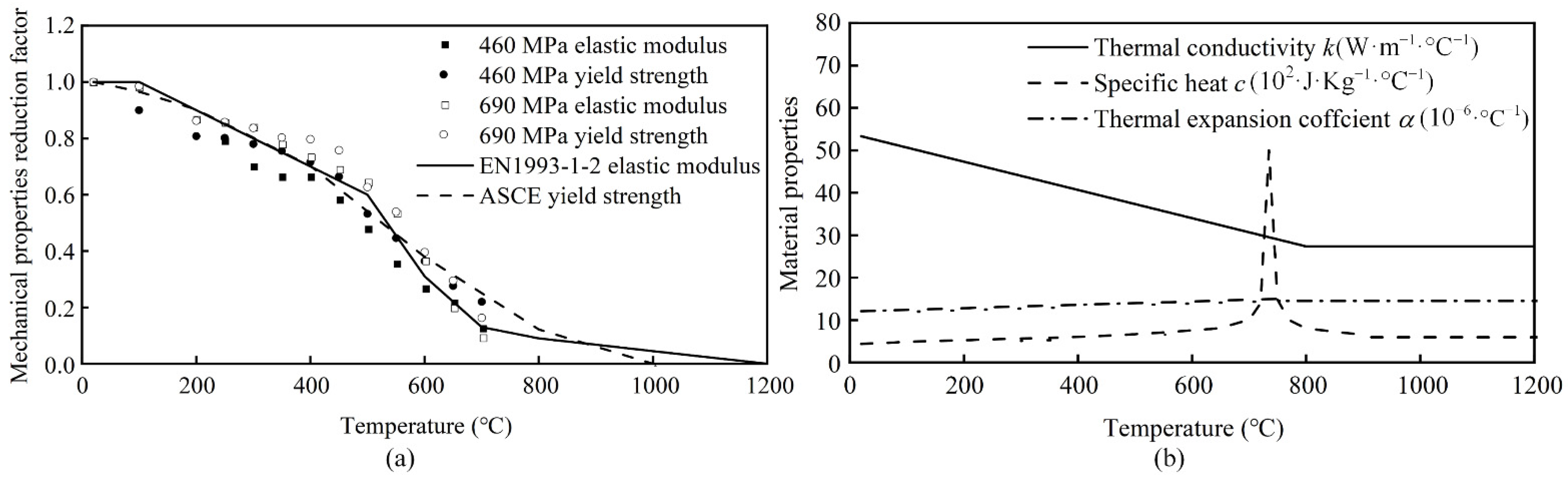
2.3. Material Constitutive Relationship

When the H-section columns are made of high-strength steel, the multilinear isotropic hardening material models proposed by Ban et al. [24] were selected as the constitutive relationships. The adopted stress–strain curve of the 460 MPa steel is shown in Figure 3a, and the stress–strain curve of the 550 MPa or higher steel is shown in Figure 3b. Specific parameters for the constitutive relationships are listed in Table 2. For steel of all strength grades, the elastic modulus E is 2.06 × 10⁵ MPa. The normal 235 MPa or 345 MPa steel adopt a bilinear isotropic hardening material model with a tangent modulus during the hardening stage Et being E/100, and Poisson’s ratio ν is 0.3. For the finite element analysis, the influence of geometric nonlinearity was taken into account. The arc length method was employed to trace the structural response path.

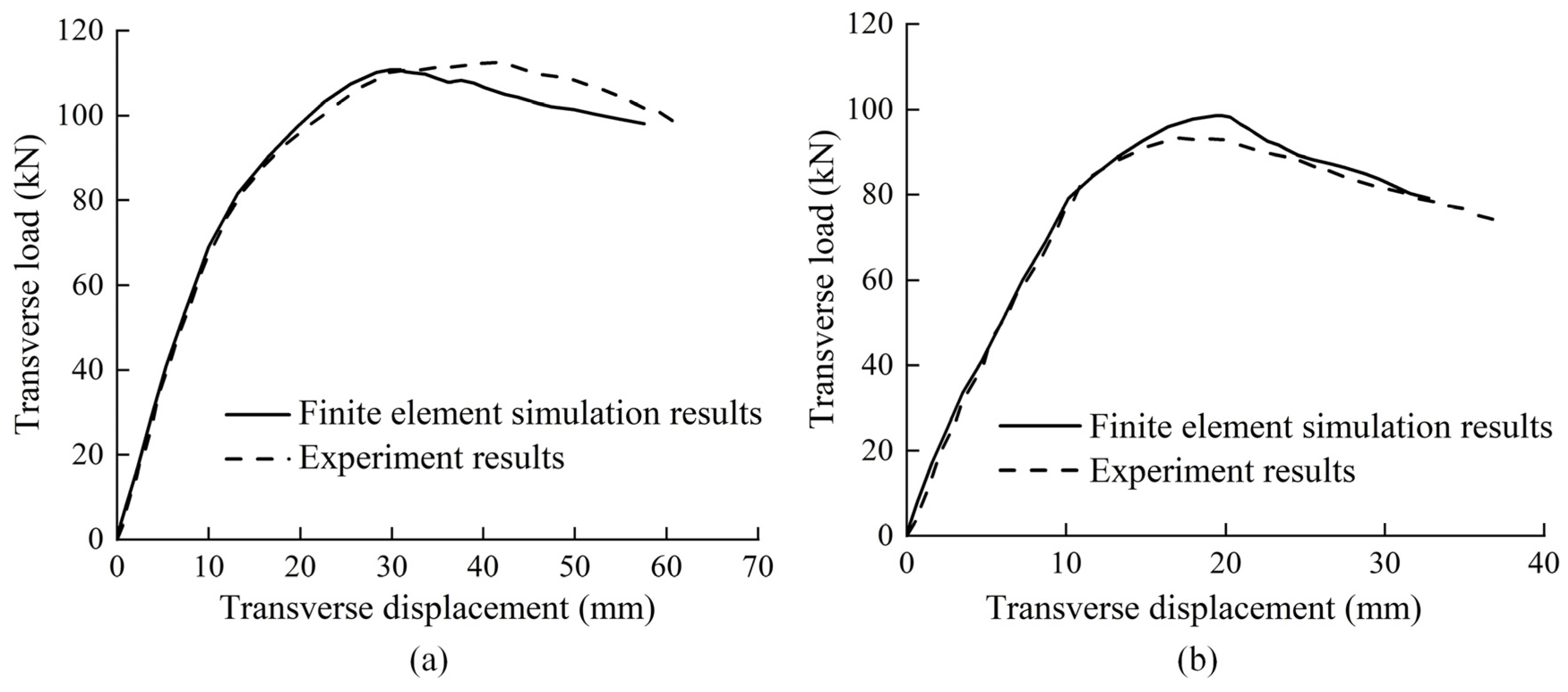
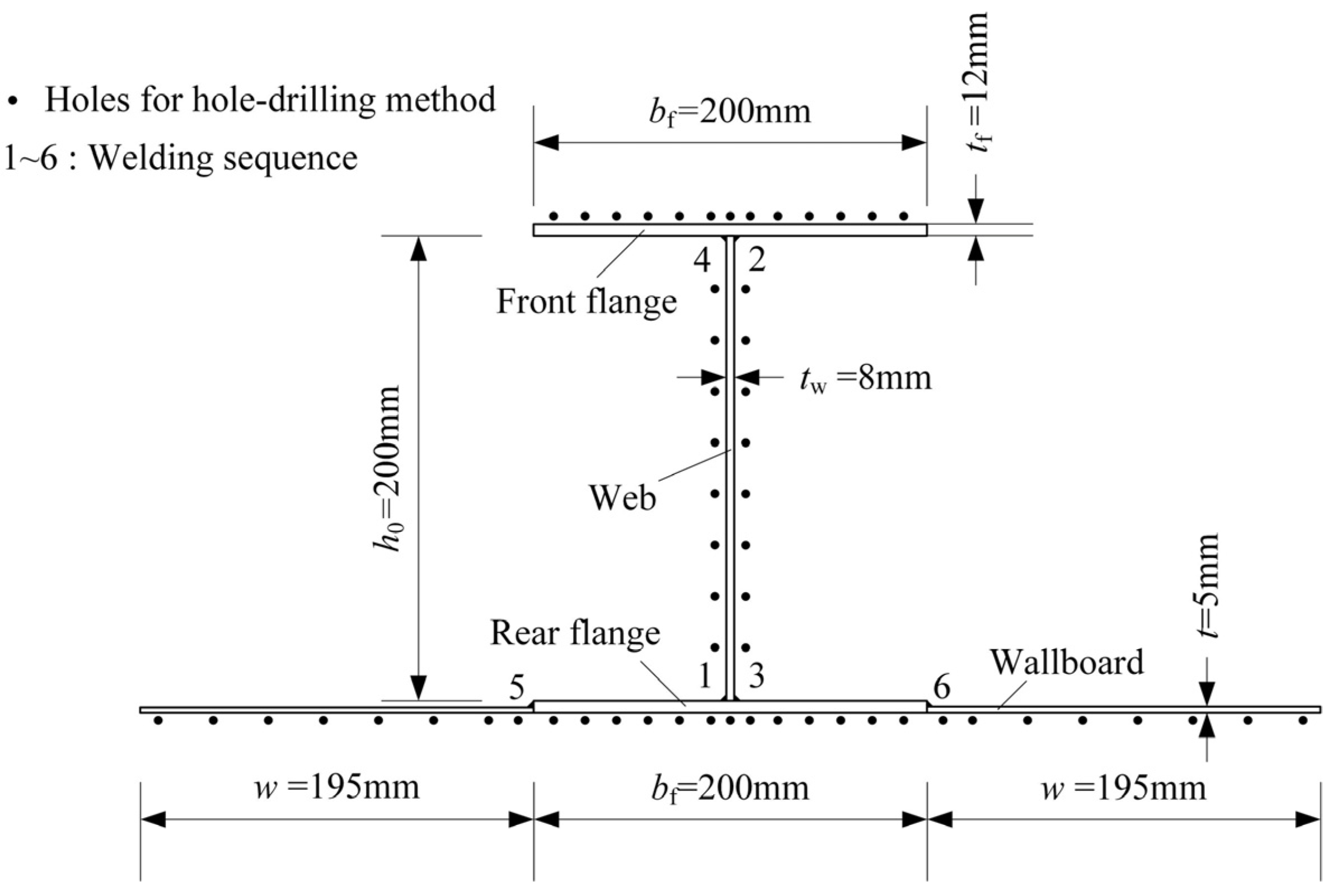
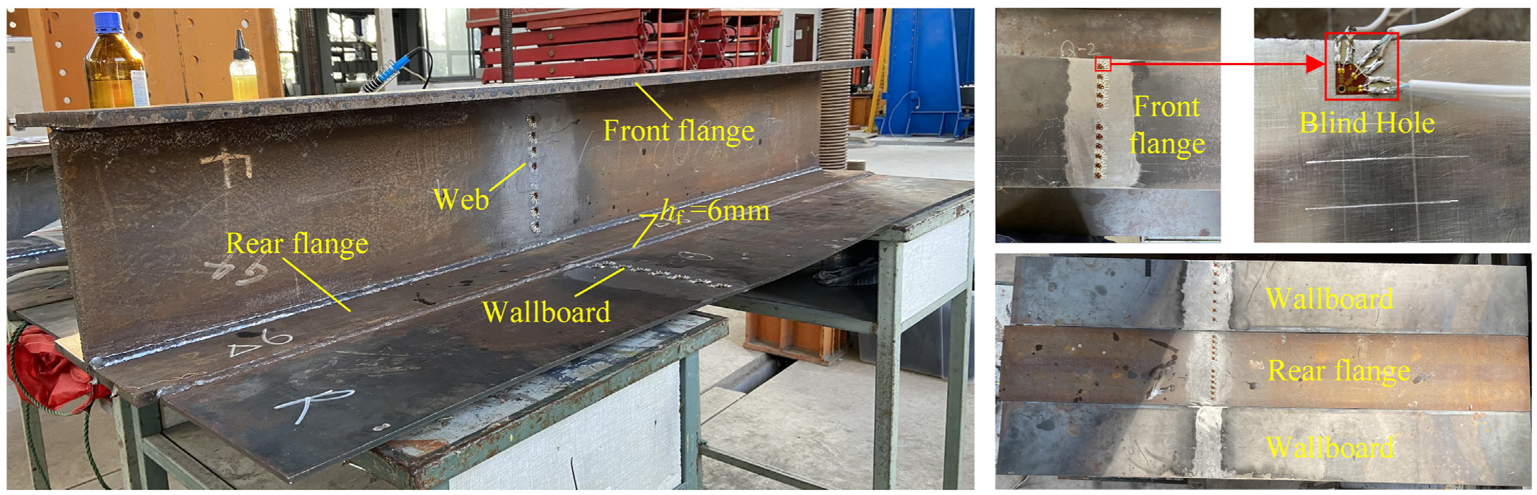
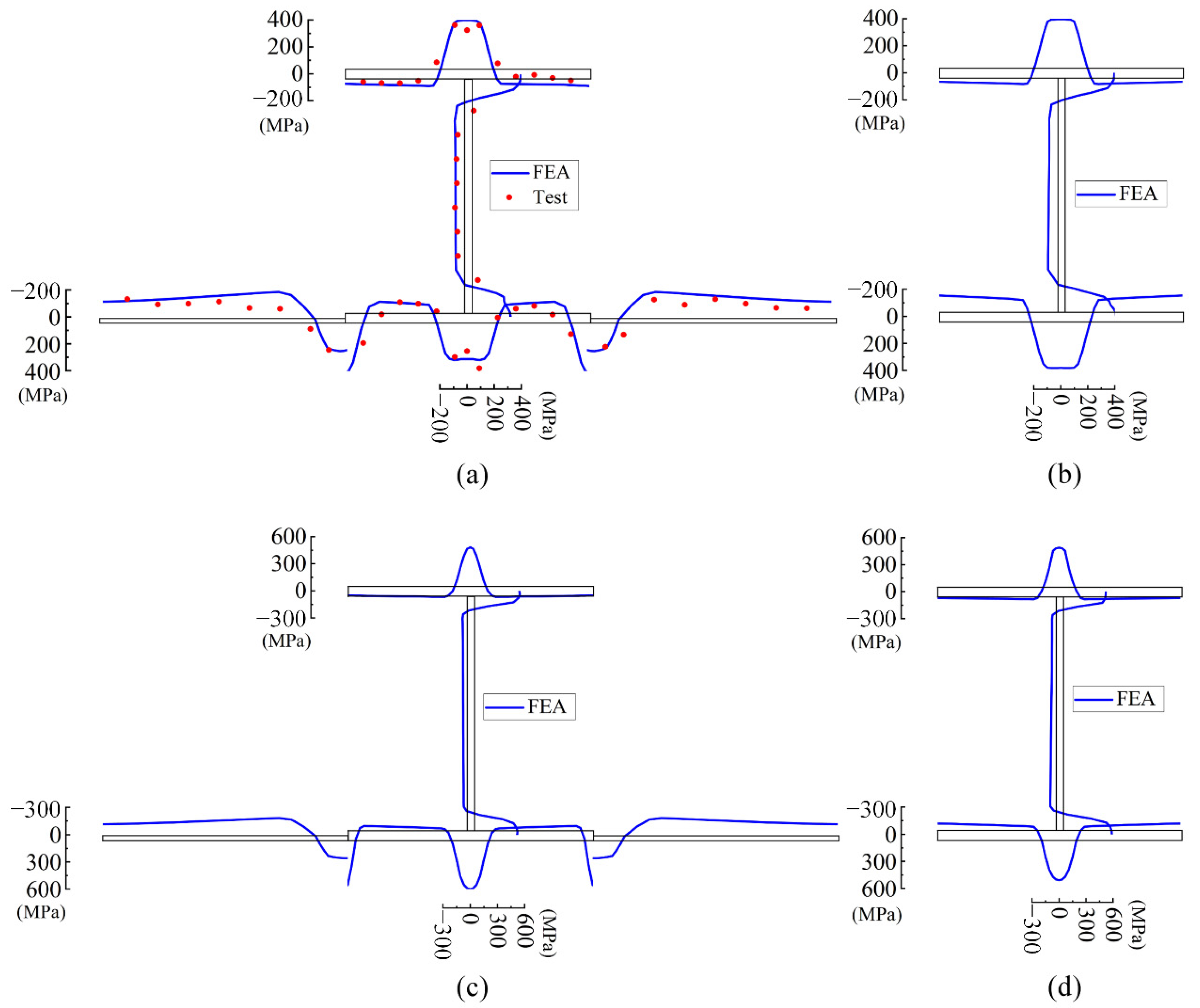
2.4. Validation of the Finite Element Analysis

Finite element models were established according to the experimental studies [25] on steel plates with biaxial stiffeners under combined loading in order to validate the finite element modeling, loading, and solving methods used in this paper. The stiffened plates are subjected to the combined action of in-plane compression and transverse pressure, which is similar to the real loading condition of wallboard–column structural system in precipitator casings. Averages of measured values of material properties of steel were adopted. According to the actual loading process, the axial load was applied first, then the transverse load was applied until failure occurred. Material and geometric nonlinearities were taken into account. A comparison of the bearing capacity values obtained by finite element simulations and experiments is shown in Table 3. Comparisons of the load–displacement curves between finite element simulations and experiments for the central nodes of two typical models are shown in Figure 4a,b, respectively.
Results of the finite element simulation are in good agreement with experimental data in terms of both the ultimate bearing capacity and load–displacement response path. Some reasons for the slight differences are: (1) although the amplitude of initial geometrical imperfection was the same, the true geometrical imperfection formed within the specimen would be different from that of the lowest eigenvalue buckling mode constructed in this paper. (2) The material properties of the actual specimen were different from the average value of the measured data and the ideal elastoplastic constitutive relationship. Overall, the results suggest the finite element model and nonlinear analysis technique employed in this paper are accurate and reliable.

2.5. Initial Geometric Imperfection

Previously, Xu and Wang [6] analyzed the influence of initial imperfections on the stability of axially compressed 235 MPa steel columns in precipitator casing and showed the columns are the most sensitive to initial flexural–torsional deformation of the front-half section. This section consists of the front flange and web and is located in the highly stressed region of the top column. Since initial geometric imperfections mainly affect the bearing capacity by generating second-order internal forces and weakening the geometric stiffness, they have little notable relationship with the strength of steel. Therefore, the aforementioned initial geometric imperfection was also introduced into the numerical analysis to fully consider its impact.
The specific method used to establish the imperfection is as follows: axial compression was applied to the top of the column of the perfect structure; simultaneously, a transverse perturbation line load qd was applied to the side of the front flange in the highly stressed region of the column (axial compressive stress was no less than 0.9 times the maximum axial compressive stress σz,max) to induce flexural–torsional deformation of the column. All loads were applied until the ultimate load was reached. The applying of the perturbation load qd is illustrated in Figure 2. When the perfect structure reached its ultimate load, the deformed structure was taken as the initial geometric imperfection mode for the imperfect model. Through trial computations and adjustments of the perturbation load magnitude, it was ensured that when the initial deformation amplitude of the column was equal to H/1000, the initial deformation of the wallboard did not exceed w/400, which met the construction quality requirements of the precipitator casing.

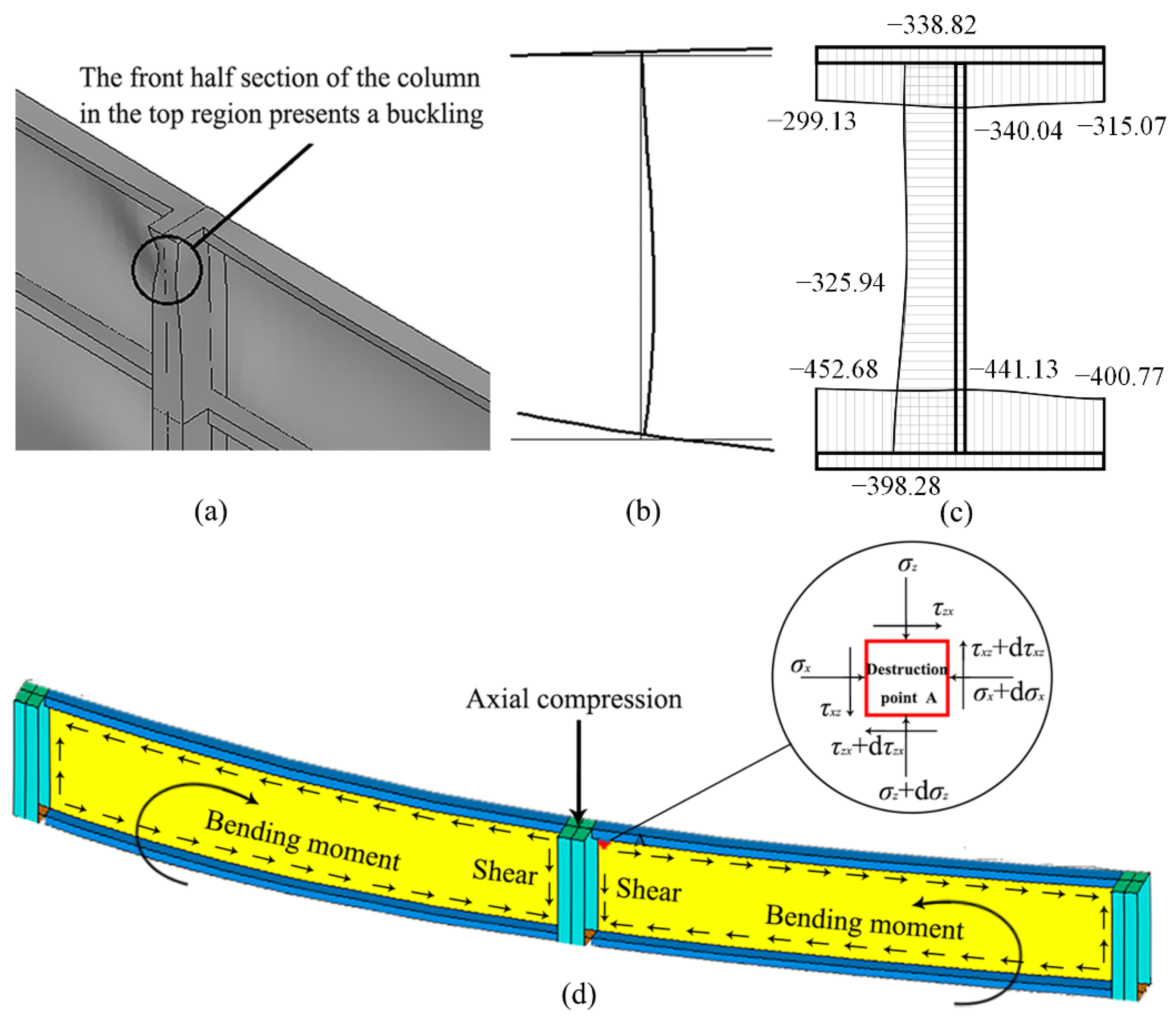
3. Failure Mechanism of High-Strength Steel Columns

Columns composed of high-strength steels with different geometries and yield strengths of 235 MPa, 345 MPa, 460 MPa, 550 MPa, and 690 MPa were simulated, and failure mechanisms were analyzed. Failure modes of each research model are presented in Table 1.
When the yield strength of the column material does not exceed 460 MPa, buckling generally occurs, and severe plasticity develops on the front half of the column section away from the wallboards. To investigate the buckling mechanism, two aspects were considered. In terms of the internal forces distribution, due to the load sharing effect of the wallboard, the magnitude of axial compression born by the column section decreases rapidly from top to bottom, and only a limited region with high axial stress exists near the top of the column. In addition, wallboards connected to the rear flange can be regarded as an extension of the rear flange. The magnitude of stress in the front flange is significantly higher than in the rear flange of the same cross section. In terms of deformation development, the stiffened wallboards effectively limit flexural or torsional deformation of the overall column section. Moreover, the rear flange is directly constrained by wallboards, while the front flange is free. Therefore, buckling of the column is necessarily triggered in the front flange located just below the top of the column, owing to high compressive stress and unconstrained deformation.
When buckling occurs, the lateral bend and torsion of the front flange leads to local bending of the web, exhibiting the interactive buckling occurring in part of the column segment where the stress is highest; that is, overall flexural–torsional buckling of the front half section and local buckling of the web occur simultaneously. In this case, the cross section of the column no longer maintains a flat plane or H-section profile. The buckling mode of the column in research model M4 is shown in Figure 5a, and the deformed shape of the column section is shown in Figure 5b. The axial stress distribution of the column when reaching the ultimate load is presented in Figure 5c.
When the yield strength of the steel reaches 550 MPa or more and the stiffness of the wallboard is relatively low, failure of the wallboard adjacent to the top of the column is most likely to occur as a result of insufficient strength (it is defined as wallboard yield failure in this paper). When the column is highly loaded, the column will not yield owing to its high yield strength. However, if there is significant axial compression, wallboards adjacent to the top of the column help support the high vertical load, resulting in high vertical compressive stress in the wallboards. At the same time, since the load is applied to the middle column, the top of the middle columns become shortened compared to the side columns. Under the loaded condition, the top panel of wallboard is similar to a deep beam, which experiences a concentrated force in the middle span. Consequently, fairly high bending compressive stresses (in X-direction) and high shear stresses are generated in the top regions of wallboard near the middle column. The loaded condition of the top panel of the wallboard is shown in Figure 5d.
Under the combined effects of high three-directional stresses, wallboards made of normal strength reach the yield strength and then lose the ability to sustain further loading. Since the height and width of the wallboard are much larger than its thickness, the critical buckling stress is very low. Additionally, considering the initial geometric imperfection, wallboards far from the columns (i.e., wallboards in the central region) undergo local buckling and then stop supporting the load during the early loading stage. Therefore, once a wallboard panel connected to a column is unable to sustain additional loading due to insufficient strength, the load cannot be effectively transferred to the central wallboard. In effect, the structural system reaches its ultimate bearing capacity. No obvious buckling deformation occurs in the column and the stress is low. In this case, the bearing capacity of the column is determined by the bearing properties of the wallboard. Thus, the advantages of using high-strength steel in the column is not fully realized.
When the yield strength of the column material reaches 550 MPa or more and the stiffened wallboard is strong enough, in general, buckling failure of the top segment of column occurs. Moreover, the buckling mechanism is similar to the previously described mechanism of the 460 MPa steel column.

4. Influence of Initial Imperfections on the Bearing Capacity of Axially Compressed Columns Made of High-Strength Steel

4.1. Influence of the Geometric Imperfection

Models M4 and M6 were used to analyze the influence of a certain initial geometric imperfection on the stability of columns made of various high-strength steels. For each case, the shape and amplitude of the initial geometric imperfection were the same and only the yield strength of the column steel was changed. The degree of influence that the imperfection has on the column buckling factor β was measured as the ratio of the difference between the buckling factor of the perfect structure and imperfect structure to the buckling factor of the perfect structure. When the yield strength of the column steel reaches 550 MPa, the structure will probably suffer wallboard yield failure rather than column buckling. However, this case was not examined because geometric imperfections typically reduce the stability of the column but not the strength of the wallboard.
The degree of influence of the initial geometric imperfection on the stability of columns of various strengths is shown in Figure 6. The results suggest that as the strength of the column steel increases, the degree of influence also gradually decreases. For structures with the same configuration and size, the second-order additional stresses generated by a certain initial geometric imperfection are determined. However, compared with the independent working column, the second-order stress increment caused by the initial geometric imperfections in the loading process is significantly smaller due to the restraints and load sharing of the wallboards. Besides, the ratio of the additional stress magnitude to the yield strength decreases with increasing column strength. Therefore, adverse effects of the initial geometric imperfection are reduced, and the stability of the column is improved.

4.2. Influence of Residual Stress

Welding residual stress is one of the main initial imperfections that affect the bearing behavior of high-strength steel structures. The welding residual stress in the structural system is derived from two sources: welding process of high-strength steel plates to form the columns and welding between normal-strength steel plates and the high-strength steel columns to form the structural system. To clarify the residual stress distribution in the structural system, a typical validation residual stress measurement test was carried out. A specimen composed of two panels of 235 MPa wallboards and an H-section 460 MPa steel column was constructed by carbon dioxide gas-shielded arc welding. The sectional geometries and the welding sequence of the six fillet welds are illustrated in Figure 7. Then, the residual stresses were measured by hole-drilling method [26] to validate the thermomechanical coupled analyses which were next conducted to simulate the welding processes. The strain gauge rosette was stuck to the marked point for each blind hole and the hole was drilled by an electric hand-drill (Figure 8). By measuring the strain variation of each gauge point, the residual stress value before release was calculated. The arrangement of hole locations is shown in Figure 7; in addition, the material mechanical properties obtained by tests at room temperature and welding parameters in construction are listed in Table 4.
For the simulation, first, a moving heat source and the “Birth and Death” technique were adopted to simulate the heat input and weld filling process according to the actual welding sequence and to obtain the transient temperature field of the structural system. Then, the transient temperature field was applied to the structure as an external load and the corresponding stress field was computed, which simulates evolution of the stress distribution in the structural system as a result of temperature changes in order to predict the final residual stress distribution. The three-dimensional thermal solid element, SOLID70, and the corresponding structural solid element, SOLID 185, were used for thermomechanical coupled analyses. Considering the symmetry of the model, only half of the structure was modeled.
The double ellipsoidal function was adopted to simulate the moving heat source (Figure 9). In the local coordinate system O’x’y’z’, the volumetric heat flux of the front and rear hemispheres of the double ellipsoid travel along the welding direction and q1(x’, y’, z’) and q2(x’, y’, z’) are given by Goldak et al. [27].
q 2 x y z = 6 3 f f Q a b c 1 π π exp ( 3 x 2 a 2 ) exp ( 3 y 2 b 2 ) exp ( 3 x 2 c 1 2 )
q 2 x y z = 6 3 f f Q a b c 2 π π exp ( 3 x 2 a 2 ) exp ( 3 x 2 b 2 ) exp ( 3 x 2 c 2 2 )
where a = 5 mm, b = 10 mm, c1 = 7.5 mm, and c2 = 10 mm; they are semi-axes of the double ellipsoid (Liu et al. [28]); Q is the welding heat input energy, Q = ηUI; η is the welding efficiency coefficient for gas-shielded welding, η = 0.85; U is the welding voltage; I is the welding current; ff and fr are the energy distribution fractions of the front and rear hemispheres, respectively; ff + fr = 2 and for most arc welding, ff = 0.6 and fr = 1.4 (Goldak et al. [29]).
Considering the accuracy and safety, temperature-dependent mechanical and thermal properties obtained from different codes were incorporated into the finite element models. For the mechanical properties of steel at elevated temperatures, the reduction factors for both yield strength and elastic modulus previously reported by Qiang et al. [30,31] were adopted for high-strength steel (460 MPa and 690 MPa); with regard to the 235 MPa steel, elastic modulus reduction factors and yield strength reduction factors were in accordance with EN 1993-1-2 [32] and ASCE [33], respectively. For the thermal properties, thermal conductivity k was obtained from EN 1993-1-2 [32]; coefficient of thermal expansion α and specific heat capacity c were in accordance with ASCE [33]. The variation functions of the mechanical and thermal properties with temperature are shown in Figure 10. Since thermal radiation has little effect on the system and to simplify calculations, only conductivity and convection were considered and the convection coefficient was 15 W·m−2·°C−1. The ambient temperature T0 = 20 °C.
The simulated and measured residual stress values of the specimen M2 are compared in Figure 11a. Both numerical simulation and test results show the similar distributions that high tensile (positive) residual stresses are generated at the welded joints, while compressive (negative) residual stresses are found in the remaining area of the section. In general, residual stresses obtained by numerical simulation and measuring test are in good agreement with each other in both the distribution shape and the amplitude. There are two possible sources of error: (1) the true mechanical and thermal properties at elevated temperature were different from the values obtained from the codes and the literature. (2) For simplicity, only half structure was considered in the symmetry simulation, whereas the welding process was not completely symmetrical in fact. In general, the employed finite element method is acceptable for the subsequent simulations presented in this paper. In addition, residual stresses were found to differ significantly along the thickness of the plate and residual stresses on outer surface were relatively small. Therefore, the averaged magnitude of through-thickness residual stresses were adopted to subsequently evaluate the influence on the structural bearing capacity.
Simulated residual stress distributions of model M2 using steel yield strengths of 460 MPa and 690 MPa are shown in Figure 11a–d. Welds between the wallboards and columns mainly influence the rear half of the section rather than the front flange. Since the buckling of the columns is derived from the front flange, welds between wallboards and columns do not have a significant influence on the column stability. However, welding generates tensile residual stresses in the wallboard panels which increase the load bearing capacity of the wallboards and indirectly improve the column stability. This is more pronounced when failure occurs due to insufficient wallboard strength. Therefore, the adverse influence of the final residual stress distribution in the wallboard–column structure is reduced owing to the unique two-step welding process, compared to independent high-strength steel H-section columns, which are formed using a single-step welding process.
To investigate the influence of welding residual stress, the residual stress generated in solid element models was unchanged introduced into the finite element models constructed from the shell elements used for the nonlinear bearing capacity calculations. A comparison of the axial compression bearing capacity of columns with and without residual stress for the two examples is presented in Figure 12. The ordinate axis shows the bearing capacity ratio with and without residual stress, Nrs,cr/Ncr.
The results suggest that for column buckling cases, increasing the strength of the steel only slightly increases the adverse influence of residual stress, which remains considerably low. From Figure 11, when the strength of steel increases, the amplitude of tensile residual stress, which is favorable to column buckling resistance, increases significantly, whereas the unfavorable compressive residual stress increases by a relatively small amount. Buckling of the column is mainly reflected in the front half of the section. When the column reaches its ultimate bearing capacity, stresses in the front flange and the front half of the web approximately reach the yield strength, as shown in Figure 5c. Prior to the external loading, residual stress causes a small amount of compression in the front section of the column, but this does not significantly increase as the strength of the steel increases. The residual stress has little effect on the compressive resistance overdraft of the front half section of the column; therefore, the impact of residual stress is small.
For the case of failure due to insufficient wallboard strength, tensile residual stress generated in the wallboard can improve its bearing capacity and the values of Nrs,cr/Ncr all exceed 1. As the strength of the column steel increases to more than 550 MPa, an increase in the tensile residual stress amplitude in the wallboard delays the yield of the wallboard, which results in a significant improvement of its bearing capacity. When residual stress is considered, the structures originally exhibit wallboard yield failure all undergo column buckling failure instead. In addition, the ratio of compressive residual stress amplitude to steel yield strength decreases. Therefore, the residual stress is obviously beneficial to the structural bearing capacity for this case.
Combined with the results on the influence of the initial geometric imperfection, the initial imperfection was found to have different influences on the bearing capacity of the structural system, which consists of columns of different strengths of steel and wallboards of 235 MPa steel. In general, as the column steel strength increases, the impact of the initial imperfection does not significantly increase but may, instead, decrease.

5. Influence of Wallboard Structural Parameters on the Bearing Capacity of Axially Compressed High-Strength Steel Columns

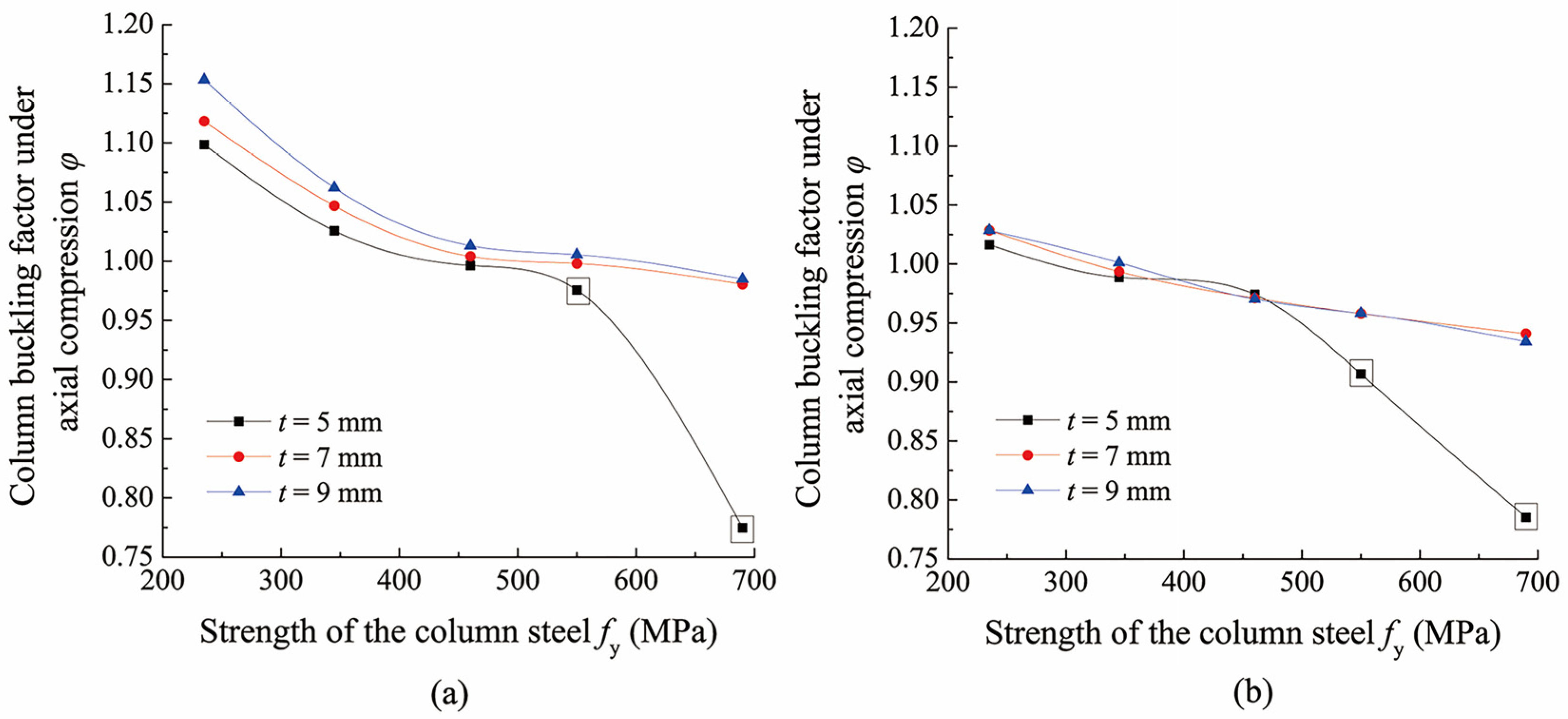
5.1. Influence of Wallboard Thickness

To investigate the influence of wallboard thickness, two research models, M2-t and M6-t, were designed. Taking M2-t as an example to illustrate the numbering rule, the basic geometries of the model series are the same as M2, except wallboard thickness t changes. The relationship between the column buckling factor and yield strength of column steel for cases of varying wallboard thickness is presented in Figure 13. Points with an extra box represent the values corresponding to wallboard yield failure and points without an extra box represent values corresponding to column buckling failure.
When the configuration and geometries remain unchanged, the buckling factor of the column decreases as the strength of steel increases. Two cases of failure mode are discussed. For column buckling, certain wallboard panels may have sufficient bearing capacity; however, the load-sharing capability and ability to constrain deformation of the column are limited. The ratio of the load shared by the wallboard to the full section yield load of the H-section column decreases as the strength of the column steel increases. This presents a stable trend and the column buckling factor gradually decreases. For the failure due to insufficient wallboard strength, the bearing capacity of the structural system is determined by the bearing capacity of the wallboard. Wallboard panels with a defined geometry have a pre-defined load bearing capacity which limits the ultimate load Ncr of the structural system. As a consequence, the column buckling factor, φ = Ncr/Ny = Ncr/AHfy, decreases significantly as the column steel strength increases. In this case, the column buckling factor does not truly reflect the buckling property of the column. However, it can still be used as the index for measuring the bearing capacity of the overall structural system consisting of wallboards and columns subjected to axial compression as well as the utilization rate of the column steel strength. For a certain geometry of the structural system, the relationship law between the column buckling factor and yield strengths of column steel is consistent, so it is not expounded in subsequent analyses.
Comparing the curves in Figure 13, when column buckling failure occurs, since the strengthening effect of wallboard on column stability is limited after all, the column buckling factor increases slightly with the increase in wallboard thickness. When failure of the wallboard occurs, the column buckling factor is determined by the wallboard strength and significantly increases with increasing wallboard thickness. If the wallboard thickness is increased to 7 mm, this can effectively guarantee that column buckling failure occurs prior to wallboard yield failure. In the case of column buckling, the buckling factor remains high regardless of the strength of the steel. Therefore, it is feasible to apply high-strength steel for the construction of the columns. In the case of wallboard failure, the buckling factor will be low and the advantages of using high-strength steel will not be fully realized.

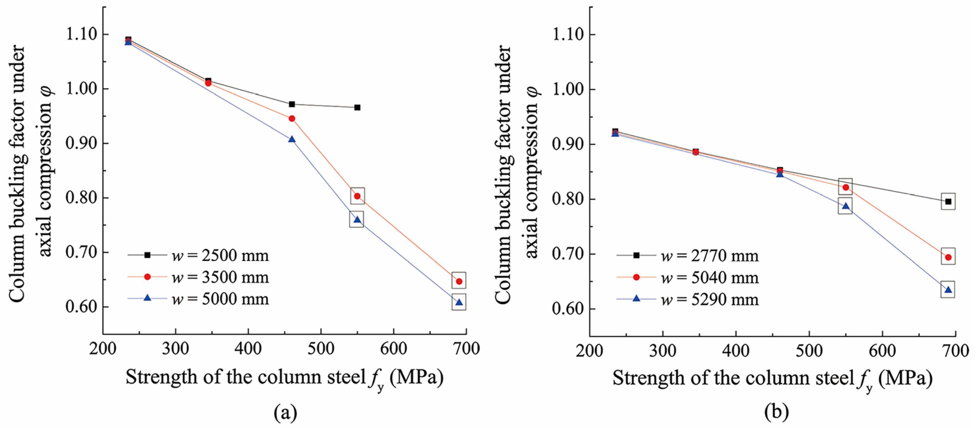
5.2. Influence of Wallboard Width

To investigate the influence of wallboard width, two research models, M2-w and M4-w, were designed. The relationship between the column buckling factor and yield strength of the column steel for different wallboard widths are shown in Figure 14.
Comparing the curves in Figure 14, it can be observed that when the strength of the column steel is relatively low (≤460 MPa), the column buckling factor is not significantly affected by increasing or decreasing the wallboard width. This is because the stressed-skin effect is provided by wallboard panels adjacent to the column, whereas wallboards far from the columns are prone to local buckling and exit the load resisting in the early loading stage, due to low stiffness and the presence of initial imperfections. Changes in wallboard width have no significant influence on the stressed-skin effect at the edge of the wallboard; therefore, the bearing capacity of the column is only slightly affected.
When the strength of the column steel is relatively high (>460 MPa), the buckling factor decreases significantly as the wallboard width increases. Increasing the wallboard width leads to a significant increase in the width-to-thickness ratio of the wallboard panel, thereby reducing the wallboard stiffness and leading to poor stability of the wallboard under the combined action of vertical compression and shear. Once wallboard stability is degraded, wallboards far from the column quit the load resisting earlier, and the subsequent increased load on the wallboard will be borne earlier by the edges of the wallboard, making the wallboard edges yield earlier. Therefore, the ultimate bearing capacity of the overall structure is reduced, resulting in a decrease in the column buckling factor.

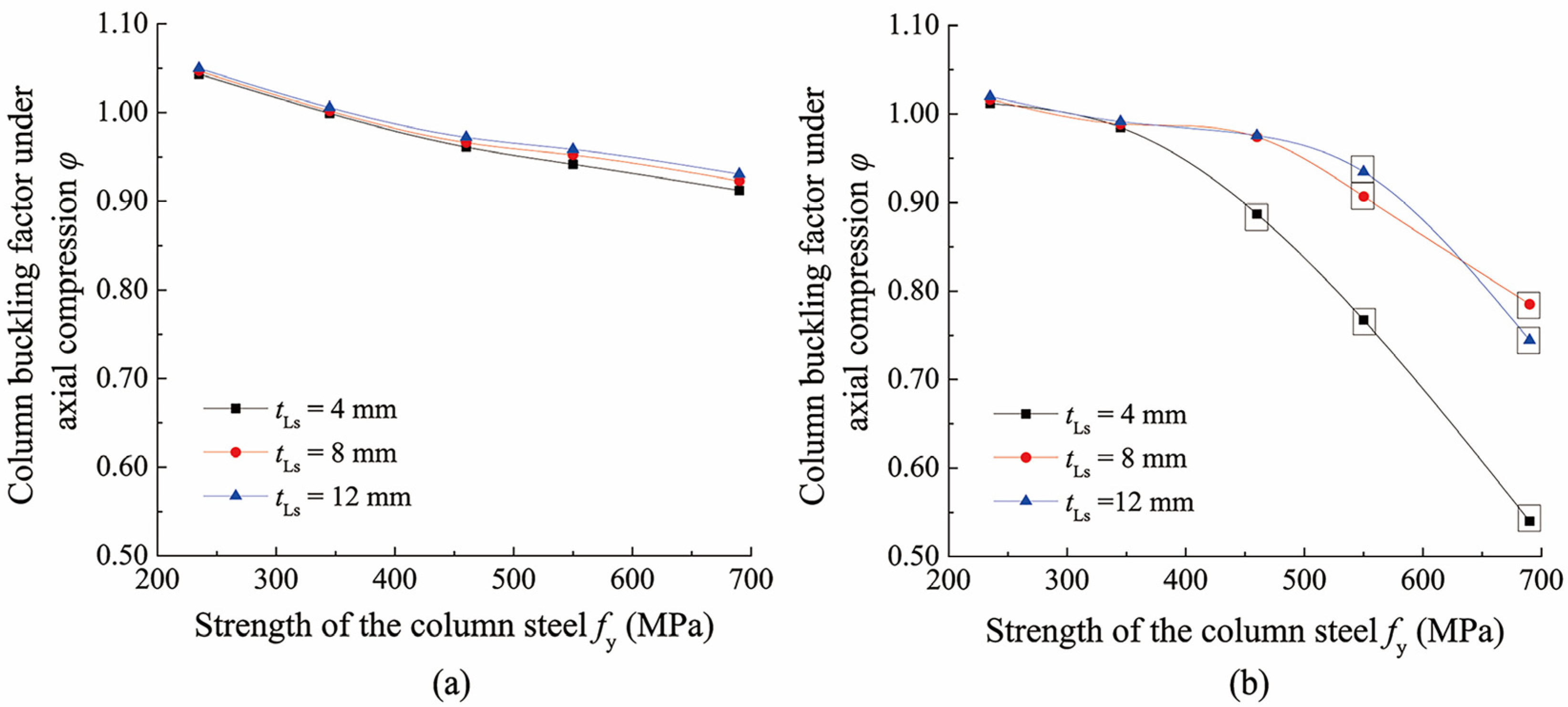
5.3. Influence of Stiffener Stiffness

Normally, angle stiffeners are welded to wallboards of precipitator casings to increase their stiffness. In this paper, two research models, M1-tLs and M6-tLs, were designed to investigate the influence of stiffener stiffness. The relationship between the column buckling factor and yield strength of the column steel for varying stiffener thicknesses are shown in Figure 15.
For model M6-tLs, when column buckling occurs (column steel strength does not exceed 345 MPa), the three curves are almost coincident with each other, indicating that reinforcement of the wallboard stiffener has little effect on the buckling factor of the column. When wallboard failure occurs (column steel strength reaches 460 MPa or more), the stress distribution on the top of the wallboard is similar to that of a deep beam under a mid-span concentrated load (loading on top of the middle column). Top stiffeners can be considered as the compressed flanges of the deep beam and mainly resist the bending internal force of wallboards in the X-direction. If the stiffener stiffness is insufficient (tLs = 4 mm), the compressive stresses in the X-direction generated in the top wallboard will be high, and the wallboard reaches the yield point earlier, exhibiting a relatively low bearing capacity. If the stiffness of the stiffener is sufficient (tLs = 8 mm or 12 mm), the bending-induced internal force is mainly resisted by the top stiffener, such that the wallboard reaches the yield point later and exhibits a higher bearing capacity. Moreover, when tLs increases to a certain level, further increases have little influence.
For the model series M1-tLs, the stiffness of the wallboard is relatively large, and the wallboard-bearing capacity is sufficient. All models present column buckling failure and the buckling factors are relatively high. Changing the stiffness of the stiffeners has little effect on the stability of the column.

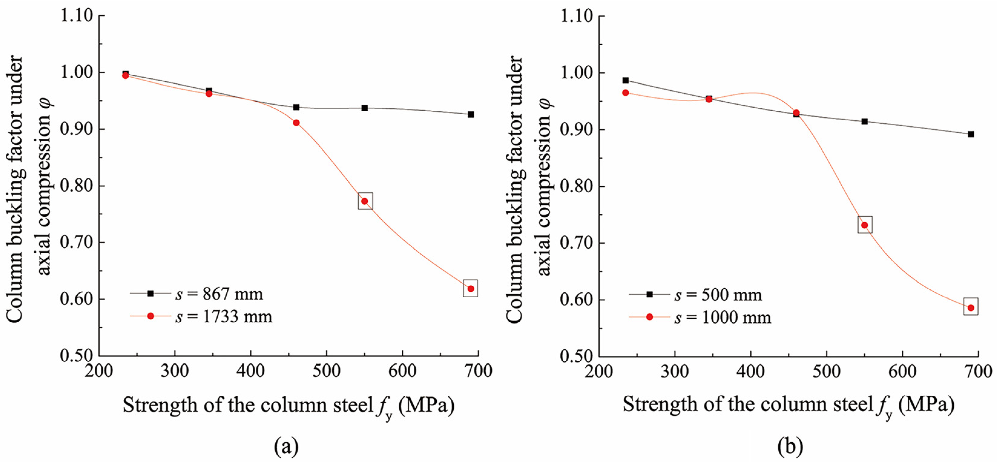
5.4. Influence of Stiffener Spacing

To investigate the influence of spacing between neighboring angle stiffeners, two research models, M4-s and M5-s, were designed. The relationship between the column buckling factor and yield strength of the column steel for varying stiffener spacings are shown in Figure 16.
It can be found that when the column buckling failure occurs, increasing the spacing between stiffeners increases the height-to-thickness ratio of the wallboard panel but does not significantly change the stressed-skin effect. Therefore, the buckling factor of the column is slightly reduced. When failure of the wallboard occurs, the increased aspect ratio of every wallboard panel reduces the wallboard critical buckling stress and weakens the overall bearing capacity of the wallboard, resulting in a significant decrease in the buckling factor of the column.
Previous analyses of wallboard structural parameters indicate that when the yield strength of the column steel is relatively low, the wallboard configuration has little influence on the bearing capacity of structural system and column buckling occurs. When the yield strength of the column steel is relatively high and the wallboard is weak, wallboard yield failure occurs. In this situation, the column buckling factor is not high, and the column steel strength cannot be fully utilized. To improve the bearing capacity of the overall structure, it is necessary to increase the wallboard thickness, especially for the top panel, and to reduce the width-to-thickness ratio and the height-to-thickness ratio of the wallboard. Simultaneously, the minimum stiffener stiffness must be limited to avoid wallboard yield prior to column buckling.

6. Influence of Column Structural Parameters on the Bearing Capacity of Axially Compressed High-Strength Steel Columns

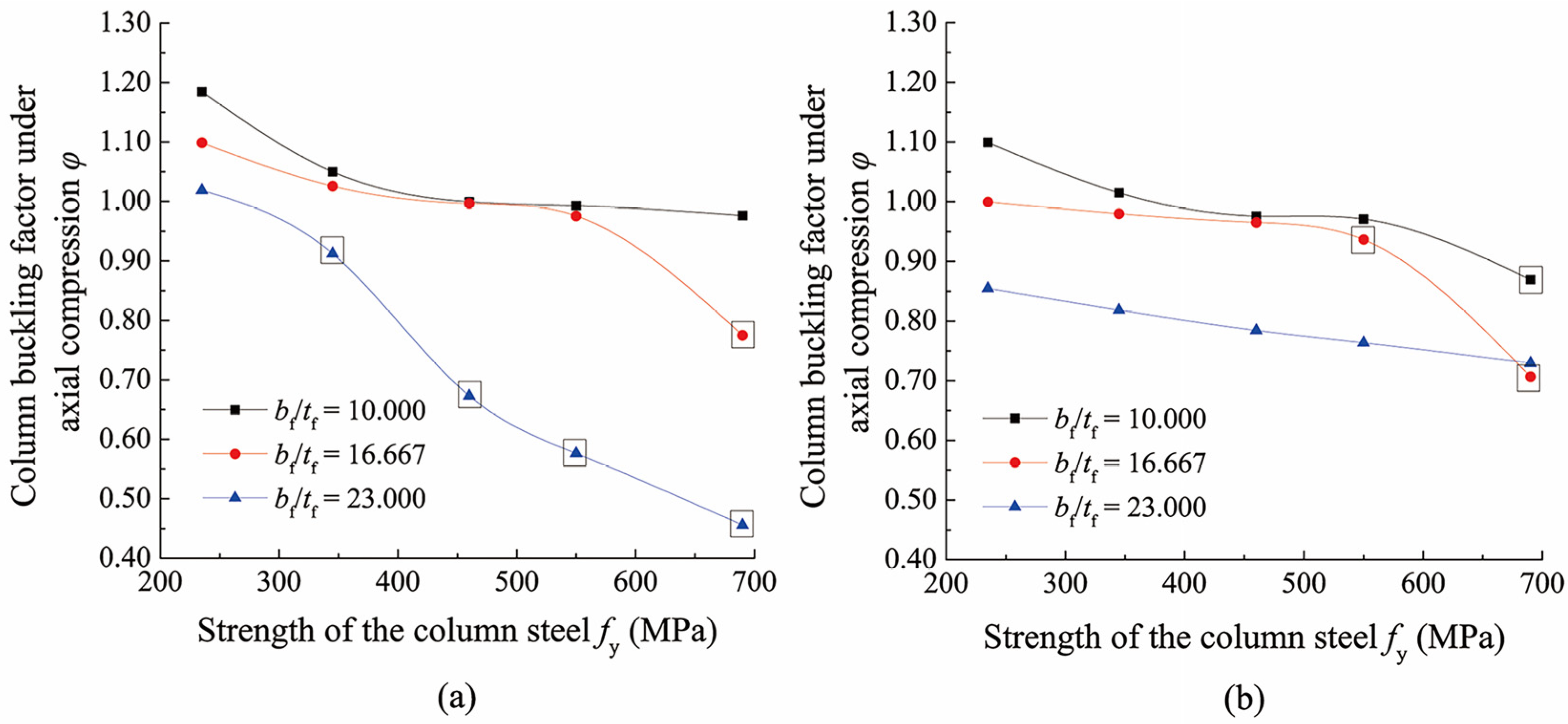
6.1. Influence of Width-to-Thickness Ratio of the Column Flange

The column exhibits interactive buckling consisting of overall flexural–torsional buckling of the front-half of the T-shaped section and local buckling of the web. The T-shaped section is composed of the front flange and web. Overall buckling of the column can be measured using the flexural–torsional slenderness ratio λyz,T. The wallboard exhibits large shear stiffness in its vertical plane and strictly constrains column translation in the X-direction, which is equivalent to the continuous X-direction translational constraint on the column. Therefore, the effective length around the y-y axis is very small; λy is close to 0; and λyz is approximately equal to λz. Thus, the torsional slenderness ratio λz,T was used as the index reflecting the overall stability of the column. In addition, local bending of the web occurs during the column buckling process. Local stability of the web as well the interactive embedding effect between the web and front flange should be taken into account. The other two indexes are proposed: width-to-thickness ratio of the front flange bf/tf and height-to-thickness ratio of the web h0/tw.
To examine the influence of the width-to-thickness ratio of the flange based on the original models, M2 and M6, different column sections were designed to guarantee λz,T and h0/tw remains unchanged and only bf/tf changes. Two research models, M2-bf/tf and M6-bf/tf, were designed. The relationship between the column buckling factor and yield strength of the column steel for varying flange width-to-thickness ratios is shown in Figure 17.
The results suggest that when column buckling occurs, the front flange is more susceptible to flexural–torsional deformation and provides less embedding constraint for the web as bf/tf increases, leading to deterioration of column stability and a decrease in the column buckling factor. When wallboard failure occurs, the stiffness of the column decreases and the wallboard shares a larger proportion of the axial load in the structural system as bf/tf increases, leading to the earlier yield failure of wallboard. Therefore, the increase in the width-to-thickness ratio of the column flange reduces the bearing capacity of the structure.

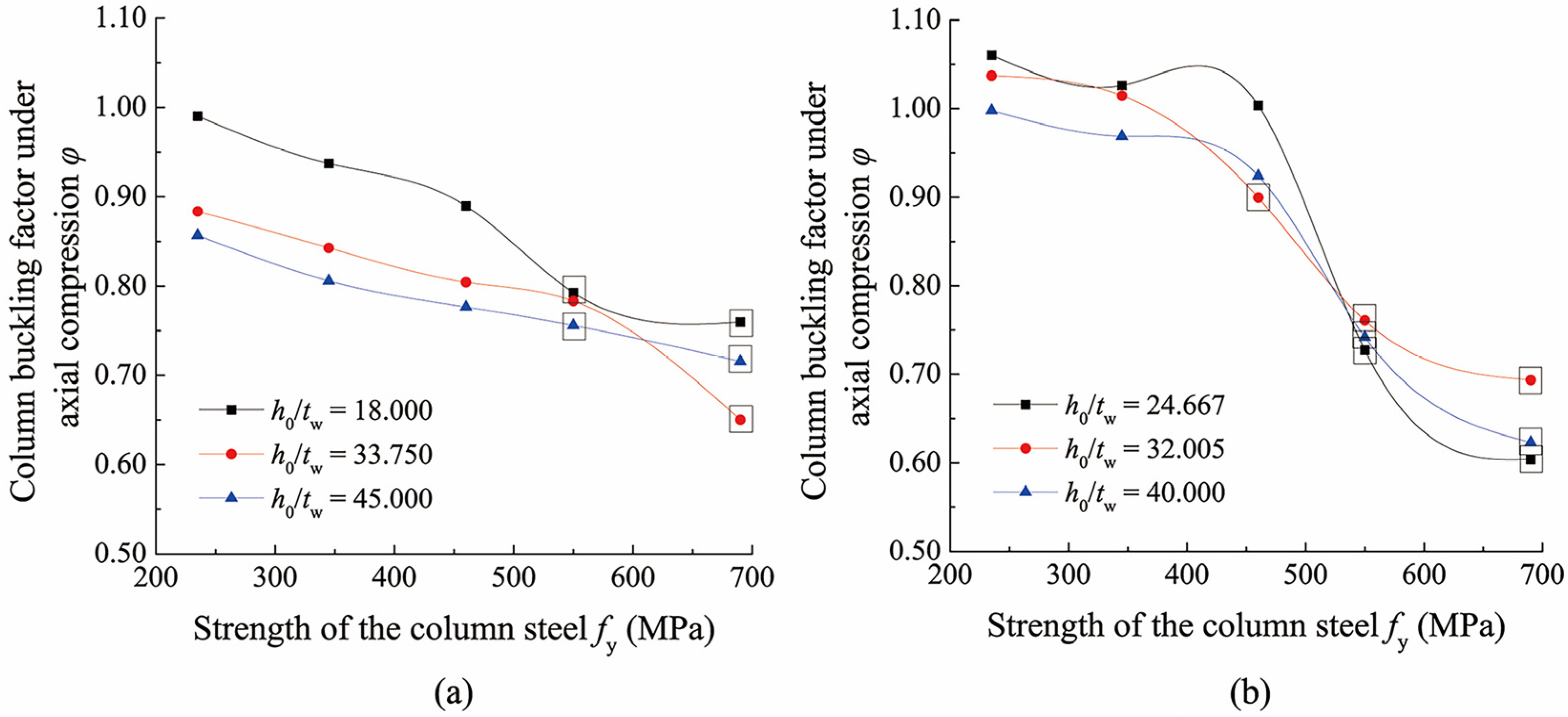
6.2. Influence of Height-to-Thickness Ratio of the Column Web

To examine the influence of height-to-thickness ratio of the web, based on the original models M4 and M6, different column sections were designed to guarantee λz,T and bf/tf remains unchanged and only h0/tw changes. Two research models, M4-h0/tw and M6-h0/tw, were designed. The relationship between the column buckling factor and yield strength of the column steel for varying web height-to-thickness ratios are shown in Figure 18.
The results indicate that when column buckling occurs, the web is more susceptible to local bending under initial imperfections as h0/tw increases, subsequently leading to torsion of the front flange. Moreover, the increase in h0/tw also weakens the constraining effect on the front flange. There are two reasons for the deterioration of column stability and decrease in the column buckling factor.
When wallboard failure occurs, the relative stiffness of the column decreases, and the proportion of load shared by the wallboard increases as h0/tw increases, thus accelerating failure of the wallboard. However, in order to keep the other geometrical parameters constant, with the increase i h0/tw, the designed section area AH of the column is reduced; therefore, the applied compression magnitude at the top of column is reduced at the same loading level (N/Ny). Consequently, the vertical compressive stress occurring in wallboard adjacent to column top and the lateral compressive stress due to the bending moment in wallboard plane are both reduced, thus slowing down the wallboard yield failure. Combining the two aspects, the relationship between the wallboard-bearing capacity and the height-to-thickness ratio of column web is not monotonous.

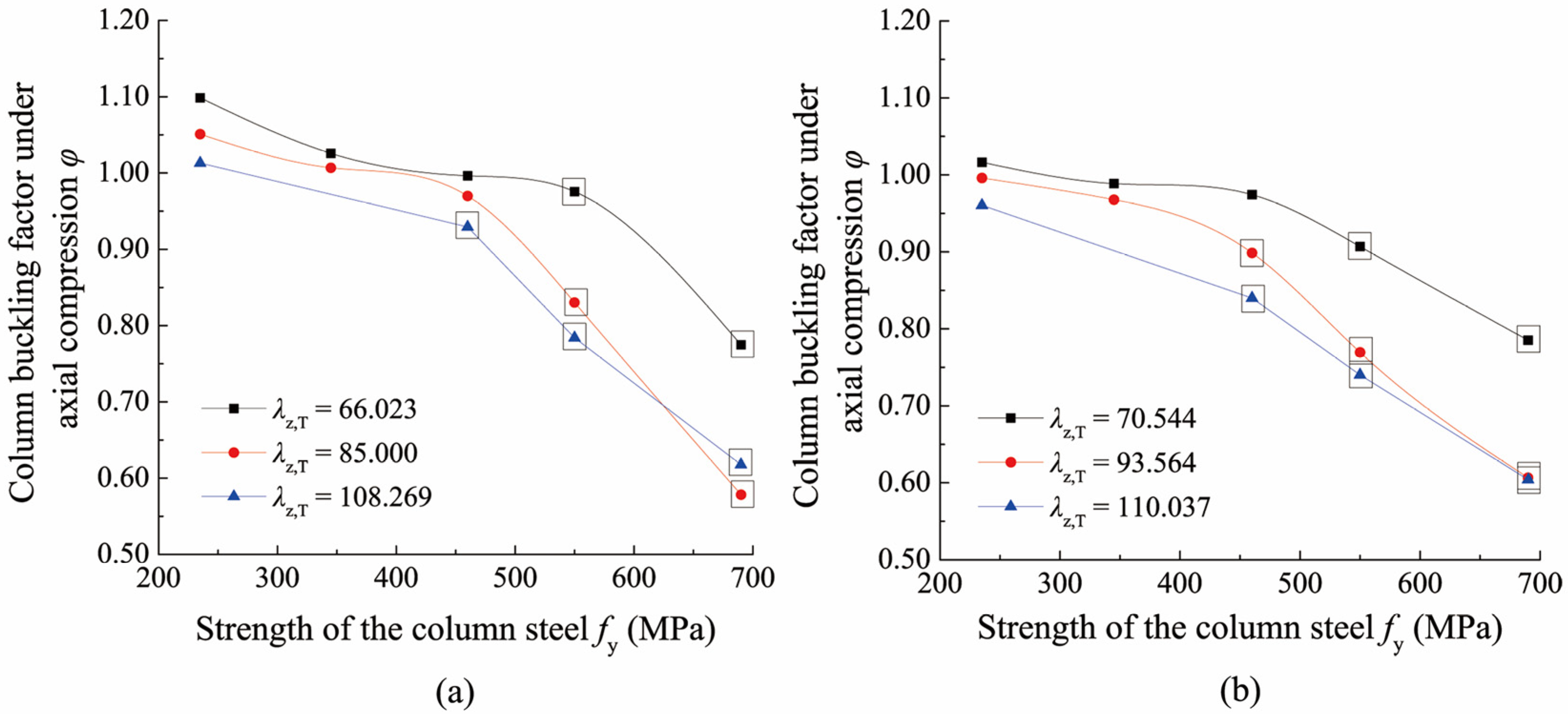
6.3. Influence of Column Torsional Slenderness Ratio

To examine the influence of the torsional slenderness ratio of the T-shaped section based on the original models M2 and M6, different column sections were designed to guarantee bf/tf and h0/tw remained unchanged and only λz,T changes. Two research models, M2-λz,T and M6-λz,T, were designed. The relationship between the column buckling factor and yield strength of the column steel for varying torsional slenderness ratios are shown in Figure 19.
When column buckling occurs, the overall torsional stiffness of the column decreases as λz,T increases, making torsional deformation more likely to develop, and thus, the column buckling factor decreases.
When wallboard failure occurs, the geometric stiffness of the column is degraded much earlier under the initial imperfection as λz,T increases. A greater proportion of the load is shared by the neighboring wallboard earlier, resulting in the earlier failure of the wallboard. Moreover, in order to keep the other geometrical parameters constant, with the increase in λz,T, the designed column cross-sectional area is increased; therefore, the applied compression magnitude at the top of column is increased at the same loading level (N/Ny). It heightens not only the vertical compressive stress occurring in wallboard but also the lateral compressive stress, leading to earlier failure of the wallboard. Thus, it can be concluded that the buckling factor of the column decreases as λz,T increases.
The analyses indicate that for columns with different strengths of steel, a decrease in the stiffness of the column degrades the buckling capacity of the column, including the width-to-thickness ratio of the front flange, height-to-thickness ratio of the web, and the flexural–torsional slenderness ratio. However, this rule is not strictly adhered to when the strength of the column steel is high and wallboard failure may occur. This is because the designed section area AH of the column changes, even when only a single examined parameter changes and all other geometric parameters remain unchanged. In fact, the absolute magnitude of compression applied at the top of the column changes, even at the same axial loading level (N/Ny), and subsequently changes the magnitude of compressive stress in the wallboard, which influences its load-bearing performance. Therefore, the relationship between the wallboard-bearing capacity and column sectional parameters may be not monotonous.

7. Conclusions

Based on the actual precipitator casing structures used in practical engineering, a nonlinear finite element method was used to systematically investigate the column bearing behavior for yield strengths of the column steel equal to 235 MPa, 345 MPa, 460 MPa, 550 MPa, and 690 MPa. The buckling factor of the column is significantly higher than that of an independent high-strength steel column due to the stressed skin support of stiffened wallboard. This indicates that the high-strength steel can achieve a higher material utilization rate when used to manufacture the stressed-skin-supported components. This provides a beneficial idea for optimizing and innovating the material application in stressed-skin-supported box-type structures, such as environmental protection equipment and modular building. According to the results, the following conclusions can be drawn:
  • The column presents interactive buckling in the top span when its steel yield strength does not exceed 460 MPa. When the yield strength reaches 550 MPa or more and the wallboard stiffness is relatively weak, the wallboard adjacent to the top of the middle column presents yield failure due to the significant biaxial compressive stresses and shear stress. The structure still experiences column buckling when the wallboard is adequately stiff.
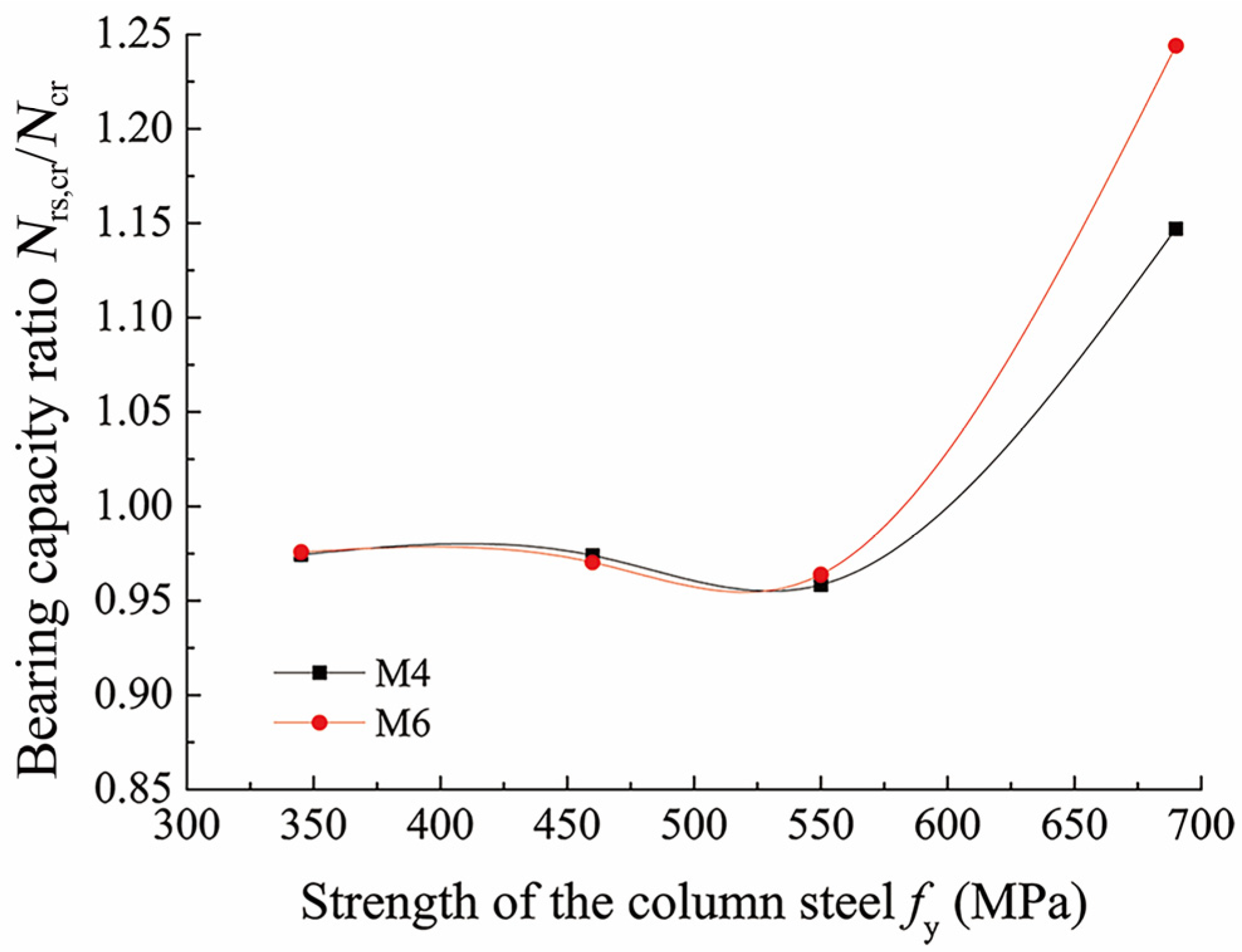
  • Adverse effects of the initial geometric imperfection decrease with an increase in the strength of the column steel. When the strength of the column steel is relatively low, the adverse effects of the residual welding stress slightly increase with the column strength. However, when the steel strength is relatively high and the wallboard failure occurs due to insufficient strength, the residual stress has a favorable effect.
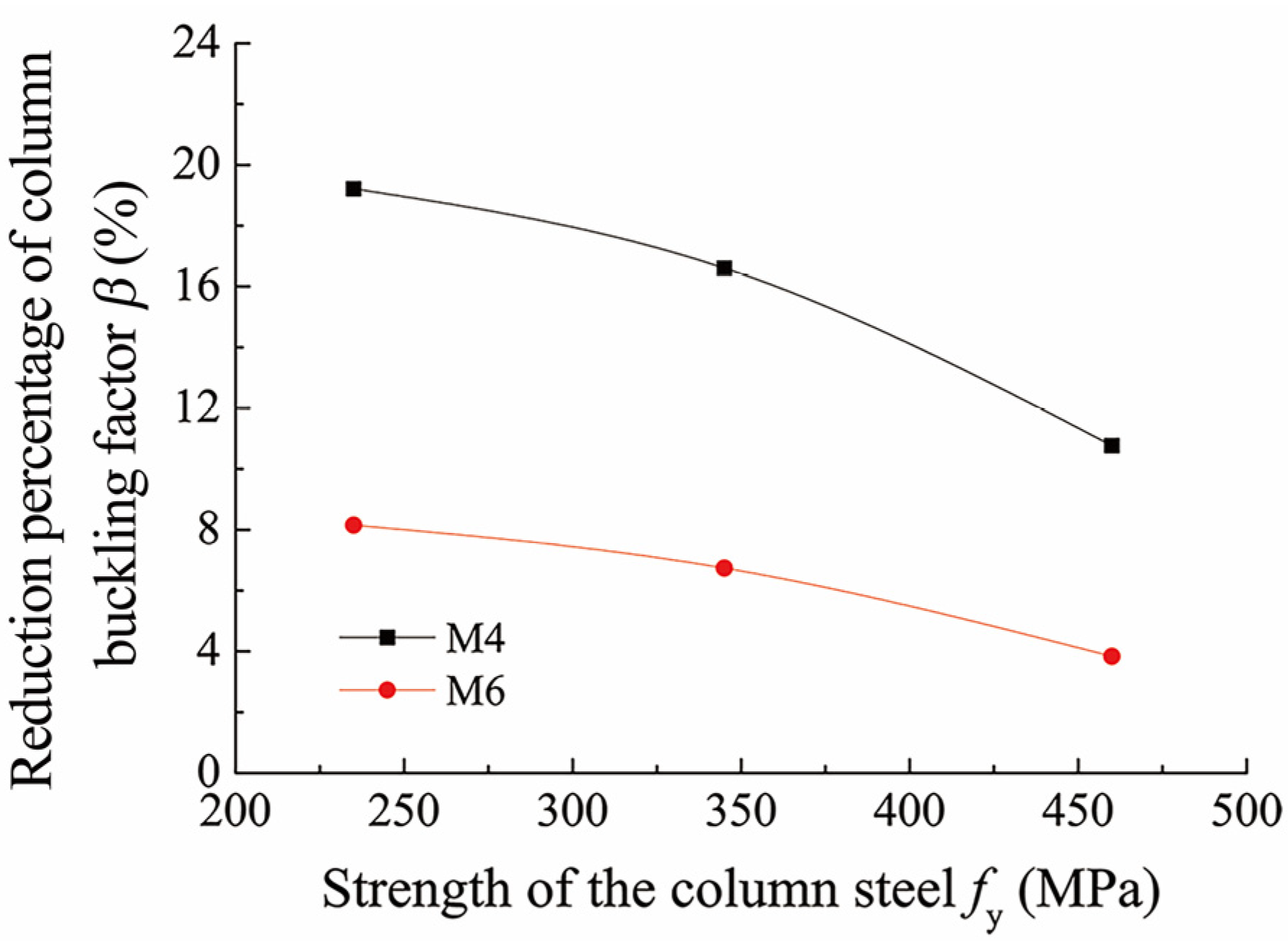
  • The buckling factor of the column decreases with an increase in the strength of the steel. A decrease in the buckling factor is stable and gradual once the column buckling occurs. The buckling factor decreases significantly once the wallboard failure occurs.
  • Wallboard structural parameters mainly influence the case of wallboard failure due to insufficient strength. The bearing capacity of the structure increases as the wallboard thickness and stiffener stiffness increase as well as the wallboard width and spacing between stiffeners decrease.
  • The bearing capacity of the column decreases with an increase in the flange’s width-to-thickness ratio, the web’s height-to-thickness ratio, and the torsional slenderness ratio.
  • When the column steel strength does not exceed 460 MPa, the column buckling factor basically remains at a high level above 0.75, indicating that the column steel’s strength can be fully utilized. When the column steel strength is 550 MPa and the wallboards are characterized by sufficient strength, the column buckling failure will occur before the wallboard failure. This can occur if the design parameters of wallboards meet the following conditions: the wallboard thickness is not less than 7 mm, the wallboard width is not more than 3500 mm, the inertia moment of the stiffener about the wallboard middle plane is not less than 848 cm4, and the stiffener spacing is not more than 1000 mm. Furthermore, according to the economical design, top wallboard panels should be properly strengthened to ensure that the high strength of the column steel can be fully utilized. When the column steel strength exceeds 550 MPa, the wallboard failure occurs first in more cases. Hence, higher steel grades are unsuitable for constructing skeleton columns in precipitator casings.
  • Only the finite element investigation was conducted in this paper. However, relevant experimental research needs to be further conducted. Lastly, after comprehensive study, the quantitative prediction formulas of the high-strength steel column-bearing capacity considering the stressed-skin effect of wallboards need to be provided.

Author Contributions

Conceptualization, D.W.; methodology, D.W.; formal analysis, M.Y.; investigation, M.Y., B.S. and D.G.; data curation, M.Y., B.S.; writing—original draft preparation, M.Y., B.S.; writing—review and editing, D.W.; visualization, M.Y., B.S. and D.G.; supervision, D.W.; funding acquisition, D.W. All authors have read and agreed to the published version of the manuscript.

Funding

This research was funded by the National Natural Science Foundation of China (No. 51308258), the Natural Science Foundation of Jiangsu (No. BK20130149), and the Postgraduate Research and Practice Innovation Projects of Jiangsu Province (No. SJCX20_0771).

Data Availability Statement

The data that support the findings of this study are available from the corresponding author, Wang, upon reasonable request.

Conflicts of Interest

The authors declared no potential conflicts of interest with respect to the research, authorship, and/or publication of this article.

References

  1. Qian, H.F.; Zhao, J.T.; Wang, Y.Q.; Wang, D.F. Internal force evaluation of columns in electrostatic precipitator casings under transverse loads considering the cooperative load bearing of columns and wallboards. Eng. Mech. 2019, 36, 227–237. [Google Scholar] [CrossRef]
  2. Rane, M.A.; Patil, G.V.; Thokal, G.; Khatwate, H. Design and optimization of electrostatic precipitator using finite element analysis tool. Int. J. Mech. Eng. Technol. 2014, 5, 90–97. [Google Scholar] [CrossRef]
  3. Ji, J.; Ding, X.H. Stiffener layout optimization of inlet structure for electrostatic precipitator by improved adaptive growth method. Adv. Mech. Eng. 2014, 2014, 979604. [Google Scholar] [CrossRef]
  4. Wang, X.W.; Li, B.; Yang, Z.J. Finite element analysis and lightweight optimization design on main frame structure of large electrostatic precipitator. Adv. Mater. Sci. Eng. 2018, 2018, 4959632. [Google Scholar] [CrossRef] [PubMed] [Green Version]
  5. Pan, L.; Xing, K.; Qian, H.; Wang, Y.; Zou, Y.; Wang, D. Bearing performance of wallboard in electrostatic precipitator casing in consideration of stressed skin effect. Acta Tech. CSAV 2016, 61, 237–254. [Google Scholar] [CrossRef]
  6. Xu, W.L.; Wang, D.F. Axial compressive buckling of a double-limb column in a precipitator casing. KSCE J. Civ. Eng. 2022, 26, 2846–2863. [Google Scholar] [CrossRef]
  7. China Machinery Industry Federation. Design Code of Steel Structures for ESP, JB/T 12127-2015; China Machine Press: Beijing, China, 2015. [Google Scholar]
  8. Ban, H.; Shi, G.; Shi, Y.; Wang, Y. Overall buckling behavior of 460 MPa high strength steel columns: Experimental investigation and design method. J. Constr. Steel Res. 2012, 74, 140–150. [Google Scholar] [CrossRef]
  9. Ban, H.; Shi, G.; Shi, Y.; Bradford, M.A. Experimental investigation of the overall buckling behaviour of 960MPa high strength steel columns. J. Constr. Steel Res. 2013, 88, 256–266. [Google Scholar] [CrossRef]
  10. Ban, H.Y.; Shi, G. Overall buckling behaviour and design of high-strength steel welded section columns. J. Constr. Steel Res. 2018, 143, 180–195. [Google Scholar] [CrossRef]
  11. Kang, S.-B.; Yang, B.; Zhou, X.; Nie, S.-D. Global buckling behaviour of welded Q460GJ steel box columns under axial compression. J. Constr. Steel Res. 2018, 140, 153–162. [Google Scholar] [CrossRef]
  12. Sun, Y.; Liang, Y.T.; Zhao, O. Testing, numerical modelling and design of S690 high strength steel welded I-section stub columns. J. Constr. Steel Res. 2019, 159, 521–533. [Google Scholar] [CrossRef]
  13. Su, A.; Liang, Y.T.; Zhao, O. Experimental and numerical studies of S960 ultra-high strength steel welded I-section columns. Thin-Walled Struct. 2021, 159, 107166. [Google Scholar] [CrossRef]
  14. Jiang, J.; Ye, Z.; Bao, W.; Wang, X.; Wang, Y.; Dai, X. Flexural buckling behaviour of 690 MPa high strength steel H-section columns. Eng. Struct. 2019, 200, 109718. [Google Scholar] [CrossRef]
  15. Huang, B.; Zhang, W.F. Local-overall interactive buckling of high strength steel welded I-section columns under axial compression. Thin-Walled Struct. 2020, 157, 106964. [Google Scholar] [CrossRef]
  16. Feng, R.; Liu, J.; Chen, Z.; Roy, K.; Chen, B.; Lim, J.B. Numerical investigation and design rules for flexural capacities of H-section high-strength steel beams with web openings. Eng. Struct. 2020, 225, 111278. [Google Scholar] [CrossRef]
  17. Nie, S.-D.; Kang, S.-B.; Shen, L.; Yang, B. Experimental and numerical study on global buckling of Q460GJ steel box columns under eccentric compression. Eng. Struct. 2017, 142, 211–222. [Google Scholar] [CrossRef]
  18. Yang, B.; Shen, L.; Kang, S.-B.; Elchalakani, M.; Nie, S.-D. Load bearing capacity of welded Q460GJ steel H-columns under eccentric compression. J. Constr. Steel Res. 2018, 143, 320–330. [Google Scholar] [CrossRef]
  19. Jiang, J.; Peng, Z.; Ye, Z.; Ye, M. Behaviour of 690 MPa high strength steel built-up H-section columns under eccentric load scenarios. Eng. Struct. 2020, 213, 110550. [Google Scholar] [CrossRef]
  20. Hu, F.X.; Shi, G.; Shi, Y.J. Experimental study on seismic behavior of high strength steel frames: Global response. Eng. Struct. 2017, 131, 163–179. [Google Scholar] [CrossRef]
  21. Hu, F.X.; Shi, G. Experimental study on seismic behavior of high strength steel frames: Local response. Eng. Struct. 2021, 229, 111620. [Google Scholar] [CrossRef]
  22. Lian, M.; Su, M.Z. Seismic testing and numerical analysis of Y-shaped eccentrically braced frame made of high-strength steel. Struct. Des. Tall Spec. Build. 2018, 27, e1455. [Google Scholar] [CrossRef]
  23. Tian, X.; Su, M.; Lian, M.; Wang, F.; Li, S. Seismic behavior of K-shaped eccentrically braced frames with high-strength steel: Shaking table testing and FEM analysis. J. Constr. Steel Res. 2018, 143, 250–263. [Google Scholar] [CrossRef]
  24. Ban, H.Y.; Shi, G.; Shi, Y.J. Overall buckling behavior and design method for axially compressed welded I-sectional columns constructed with different grades of high-strength steels. China Civ. Eng. J. 2014, 47, 19–28. (In Chinese) [Google Scholar] [CrossRef]
  25. Shanmugam, N.; Dongqi, Z.; Choo, Y.; Arockiaswamy, M. Experimental studies on stiffened plates under in-plane load and lateral pressure. Thin-Walled Struct. 2014, 80, 22–31. [Google Scholar] [CrossRef]
  26. GB/T 31310-2014; Metallic Material-Determination of Residual Stress: Hole Drilling Strain-Gauge Method. Standards Press of China: Beijing, China, 2014. (In Chinese)
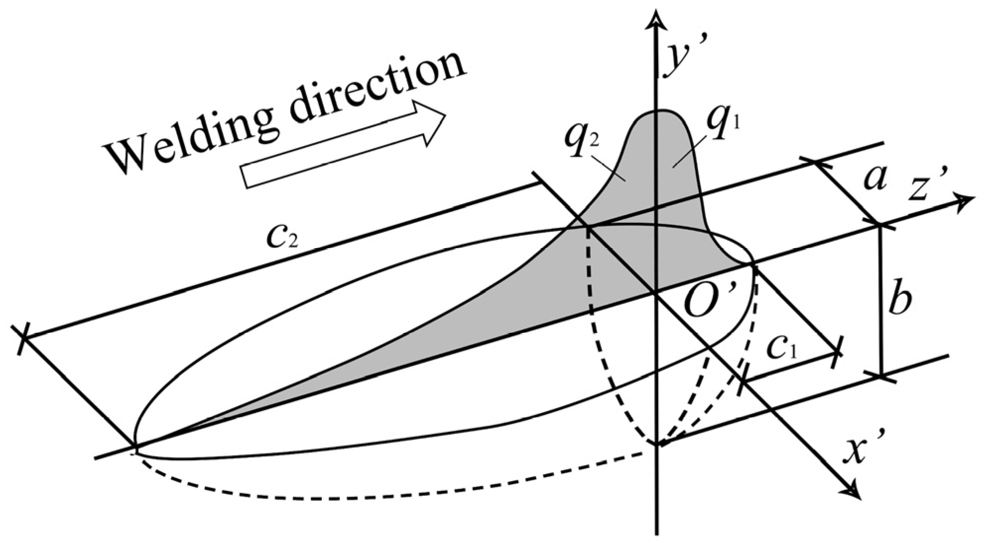
  27. Goldak, J.A.; Chakravarti, A.; Bibby, M. A new finite element model for welding heat sources. Metall. Trans. B 1984, 15, 299–305. [Google Scholar] [CrossRef]
  28. Liu, X.; Chung, K. Experimental and numerical investigation into temperature histories and residual stress distributions of high strength steel S690 welded H-sections. Eng. Struct. 2018, 165, 396–411. [Google Scholar] [CrossRef]
  29. Goldak, J.A.; Akhlaghi, M. Computational Welding Mechanics; Springer Science & Business Media: New York, NY, USA, 2005. [Google Scholar]
  30. Qiang, X.H.; Wu, K.D.; Jiang, X.; Luo, Y. Study on mechanical properties of high strength steel S460 at elevated temperatures and fire-resistance design recommendations. J. Hunan Univ. (Nat. Sci.) 2018, 45, 37–45. (In Chinese) [Google Scholar] [CrossRef]
  31. Qiang, X.H.; Bijlaard, F.; Kolstein, H. Dependence of mechanical properties of high strength steel S690 on elevated temperatures. Constr. Build. Mater. 2012, 30, 73–79. [Google Scholar] [CrossRef]
  32. BS EN 1993-1-2:2005; Eurocode 3: Design of Steel Structures-Part 1-2: General Rules-Structural Fire Design. CEN: Brussels, Belgium, 2005.
  33. ASCE (American Society of Civil Engineering). Structural Fire Protection; ASCE (American Society of Civil Engineering): New York, NY, USA, 1992. [Google Scholar]
Figure 1. Overall structure diagram of an electrostatic precipitator.
Buildings 12 01737 g001
Figure 2. Schematic drawing of wall–column structure system.
Buildings 12 01737 g002
Figure 3. Stress–strain relationship of high-strength steel: (a) with yield platform and (b) without yield platform.
Buildings 12 01737 g003
Figure 4. Comparison of load–displacement curves of finite element simulations versus experiment records: (a) Specimen A4, (b) Specimen B5.
Buildings 12 01737 g004
Figure 5. Column buckling modes (model M4): (a) Buckling mode in top region of column (460 MPa steel), (b) Deformed column section (460 MPa steel), (c) Axial stress distribution of the column when reaching the ultimate load (460 MPa steel), (d) Loaded condition of the top panel of wallboard.
Buildings 12 01737 g005
Figure 6. Influence of initial geometric imperfection on the stability of columns with various steel strengths.
Buildings 12 01737 g006
Figure 7. Schematic diagram for specimen section and distribution of holes.
Buildings 12 01737 g007
Figure 8. Welding residual stress measuring test setup of the hole-drilling method.
Buildings 12 01737 g008
Figure 9. Double ellipsoidal heat source model.
Buildings 12 01737 g009
Figure 10. Mechanical and thermal properties of steel at elevated temperatures: (a) mechanical properties reduction factors, (b) thermal properties.
Buildings 12 01737 g010
Figure 11. Residual stress distribution for model M2 (unit: MPa): (a) Comparison of measured and simulated values (nominal 460 MPa steel), (b) Simulated values of column section (nominal 460 MPa steel), (c) Simulated values of overall structural system (690 MPa steel column), and (d) Simulated values of column section (690 MPa steel).
Buildings 12 01737 g011
Figure 12. Influence of welding residual stress on bearing capacity of columns with varying steel strengths.
Buildings 12 01737 g012
Figure 13. Relationship between column buckling factor and yield strength of column steel for varying wallboard thickness: (a) Model M2-t and (b) Model M6-t.
Buildings 12 01737 g013
Figure 14. Relationship between column buckling factor and yield strength of the column steel for varying wallboard widths: (a) Model M2-w, (b) Model M4-w.
Buildings 12 01737 g014
Figure 15. Relationship between column buckling factor and yield strength of column steel for varying stiffener thickness: (a) Model M1-tLs, (b) Model M6-tLs.
Buildings 12 01737 g015
Figure 16. Relationship between column buckling factors and yield strengths of column steel for varying stiffener spacing: (a) Model M4-s, (b) Model M5-s.
Buildings 12 01737 g016
Figure 17. Relationship between column buckling factor and yield strength of column steel for varying flange width-to-thickness ratios: (a) Model M2-bf/tf, (b) Model M6-bf/tf.
Buildings 12 01737 g017
Figure 18. Relationship between column buckling factor and yield strength of column steel for varying web height-to-thickness ratio: (a) Model M4-h0/tw, (b) Model M6-h0/tw.
Buildings 12 01737 g018
Figure 19. Relationship between column buckling factor and yield strength of the column steel for varying torsional slenderness ratio: (a) Model M2-λz,T, (b) Model M6-λz,T.
Buildings 12 01737 g019
Table 1. Geometric parameters and failure modes of research models.
Model NumberSection of the ColumnH
(mm)
l
(mm)
w
(mm)
t
(mm)
s
(mm)
Section of the StiffenerFailure Mode of Structure
235–460 MPa Steel550–690
MPa Steel
M1H250 × 175 × 7 × 1111,990351035006702∟125 × 80 × 8bucklingbuckling
M2H200 × 200 × 8 × 1211,9903510350051170∟100 × 63 × 6bucklingyield
M3H294 × 200 × 8 × 1217,060520040305867∟125 × 80 × 8bucklingbuckling
M4H294 × 200 × 8 × 1217,0605200403051040∟125 × 80 × 8bucklingyield
M5H250 × 250 × 9 × 1416,460400042005500∟125 × 80 × 8bucklingbuckling
M6H250 × 250 × 9 × 1416,4605000420051000∟125 × 80 × 8bucklingyield
Note: columns are made of steel with strengths varying from 235 MPa to 690 MPa, and wallboards and angle stiffeners are made of 235 MPa steel.
Table 2. Specific parameters for constitutive models of steel.
fy (MPa)fu (MPa)εstεu
235
345
4605500.020.14
5506700.09
6907700.08
Table 3. Comparison of bearing capacity between finite element simulations and experiments.
Experiment Model NumberAxial Load N (kN)Transverse Load q (kN)Relative Error
(qFEMqEXP)/qEXP (%)
Experimental Value qEXP (kN)Finite Element Value qFEM (kN)
A4400112.8110.9−1.7%
A550075.176.41.7%
B4200145.7136.3−6.4%
B540093.399.66.8%
Table 4. Material mechanical properties and welding parameters.
ComponentMaterial Mechanical PropertiesWelding Parameters
Modulus of Elasticity E (MPa)Yield Strength fy (MPa)Poisson’s Ratio νI (A)U (V)Welding Speed (mm/s)
H-section column1.94 × 1054900.31180283.92
Wallboard1.90 × 1053410.33180225.67
Publisher’s Note: MDPI stays neutral with regard to jurisdictional claims in published maps and institutional affiliations.

