
A Technique for Optimizing the Sequences Yielding under Load of Concentrically-Braced Steel Frames

Abstract
:1. Introduction
2. Yield Mechanism Control Method
2.1. Component Bearing Capacity
2.2. Parameter Ranges (Top Floor Calculation)
2.2.1. Parameter Ranges of d
2.2.2. Parameter Ranges of D
2.2.3. Parameter Ranges of Column
2.3. Parameter Ranges (Typical Floor Calculation)
2.3.1. Parameter Ranges of d
2.3.2. Parameter Ranges of D
2.4. Structural Parameter Ranges Calculation Method of Other Sections
2.4.1. Parameter Ranges of ls (Top Floor)
2.4.2. Parameter Ranges of Ls (Top Floor)
2.4.3. Parameter Ranges of ls and Ls (Typical Floor)
3. Experimental Verification of the Method
3.1. Top Floor
3.2. Typical Floor
4. Verification by Finite Element Modeling
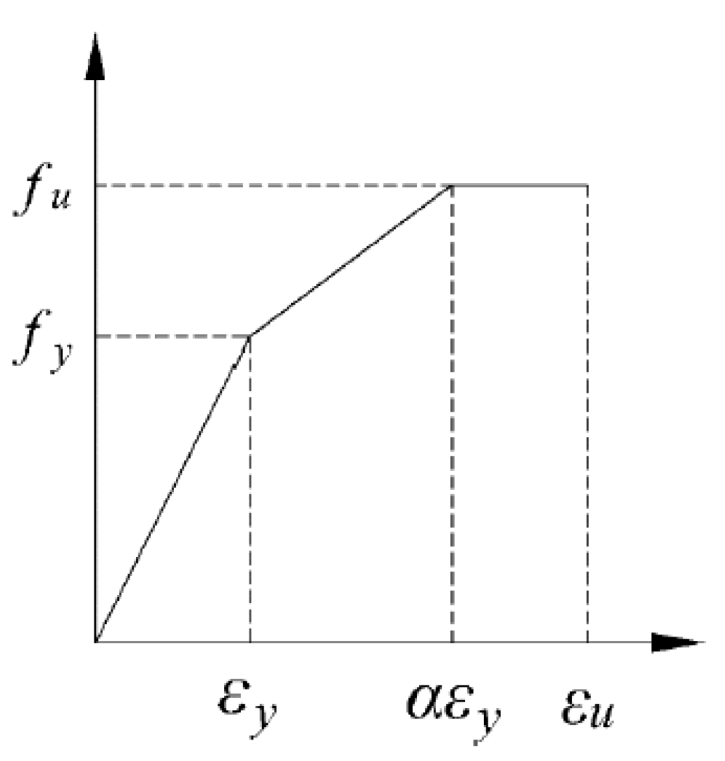
4.1. Material Properties
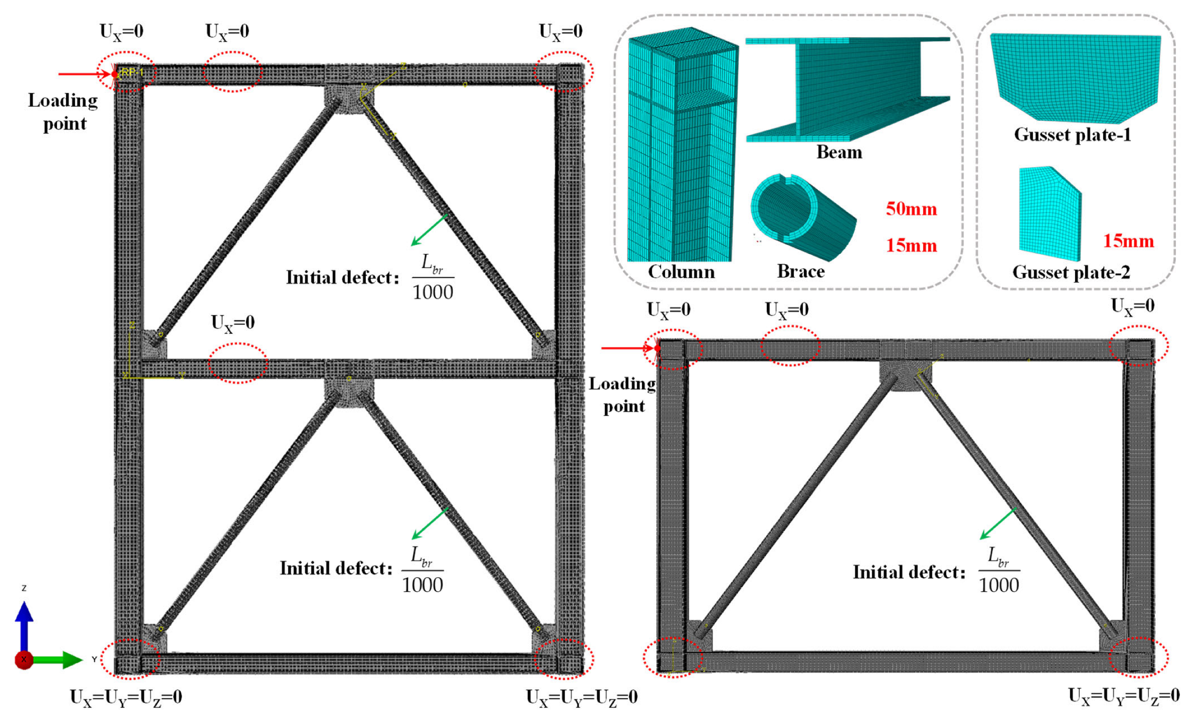
4.2. Modeling
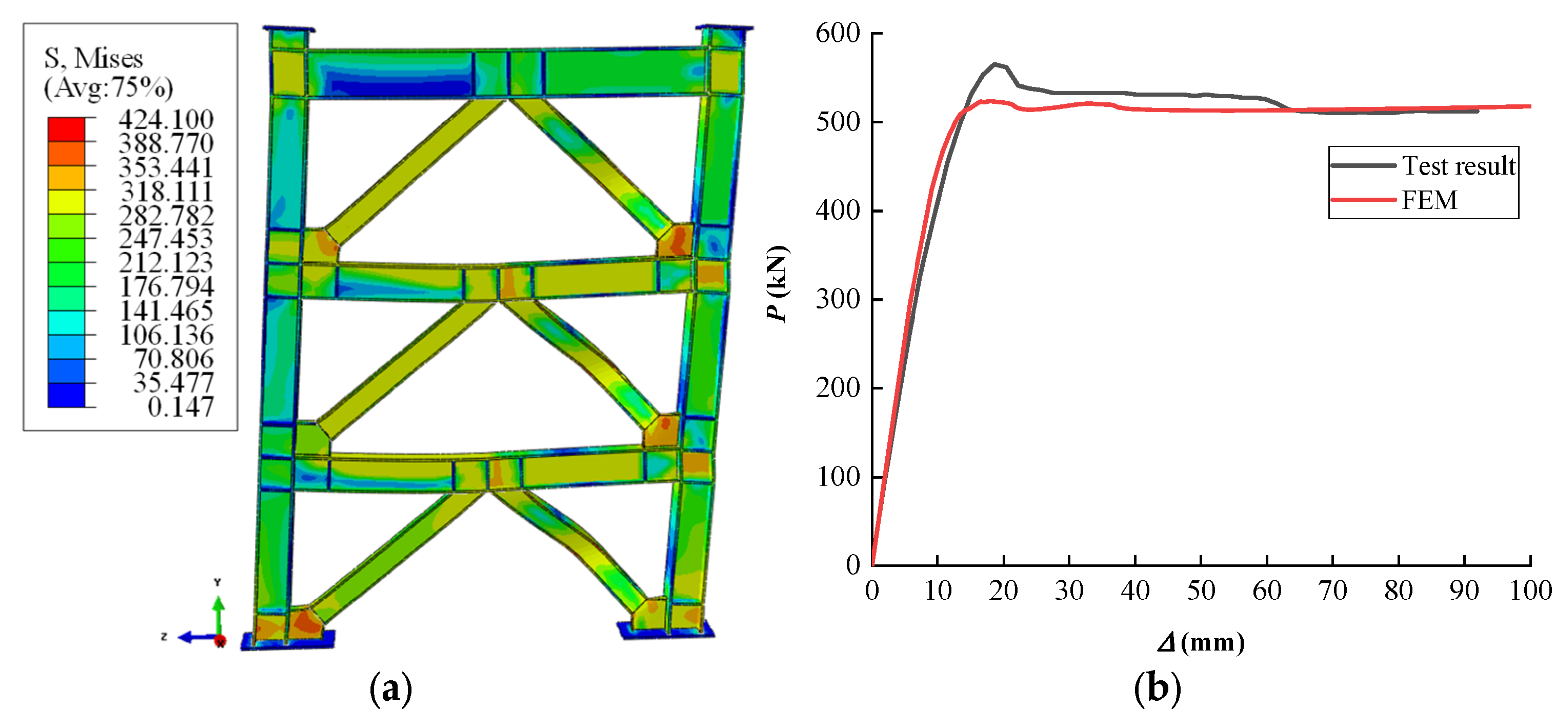
4.3. Validation of Finite Element Modeling
4.4. Finite Element Modeling Parameters
- For brace axial compression ratio is 0, the ranges of braces’ external diameters were calculated as 74 mm < D < 144 mm.
- Inserting the parameters of the beam and the external diameter, the ranges of the structural typical floor brace inner diameters were calculated as 115 mm < d < 123 mm.
- The ranges of column should be satisfied with hcwtcw > 5771.5 mm2, wcf > 250 mm.
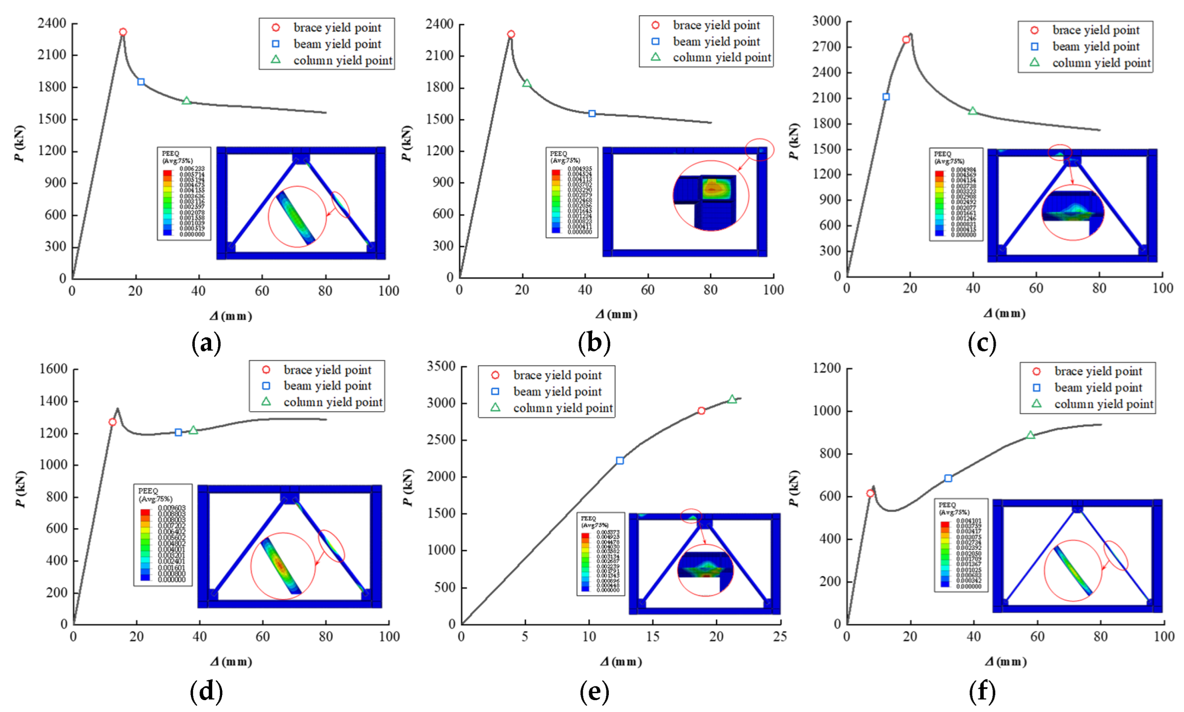
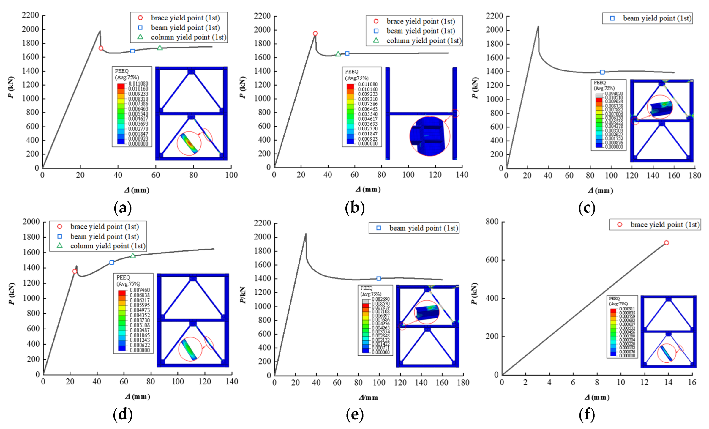
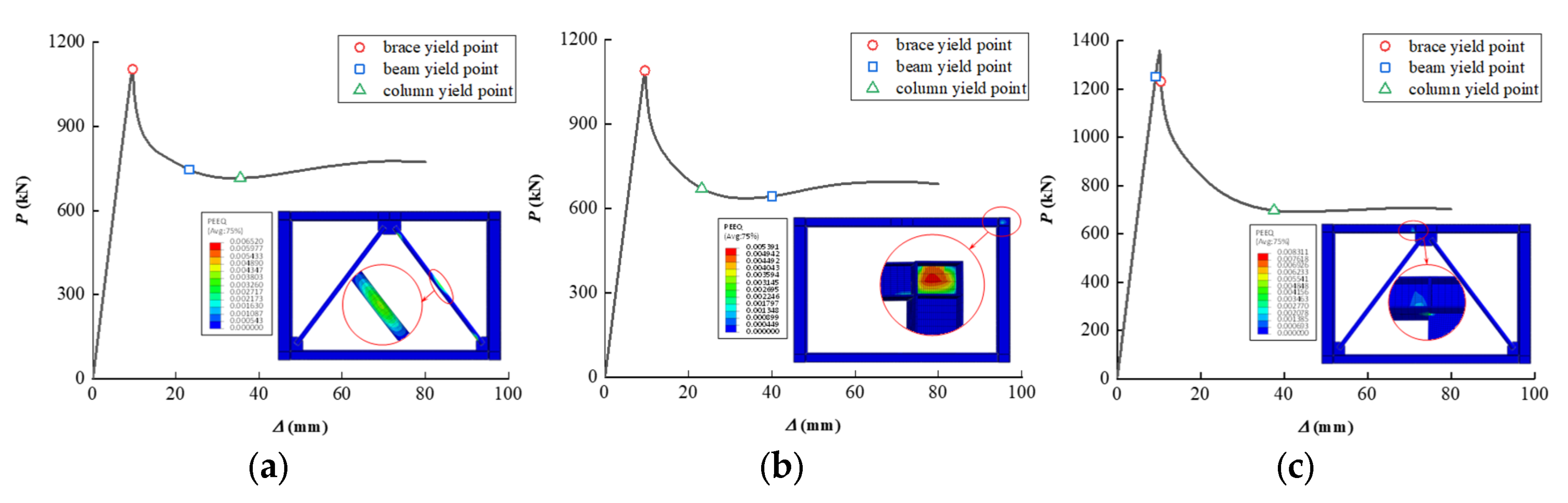
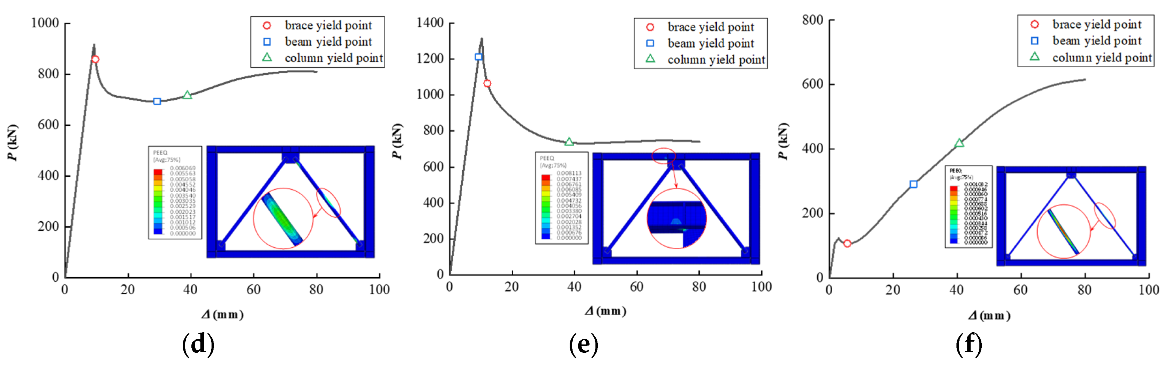
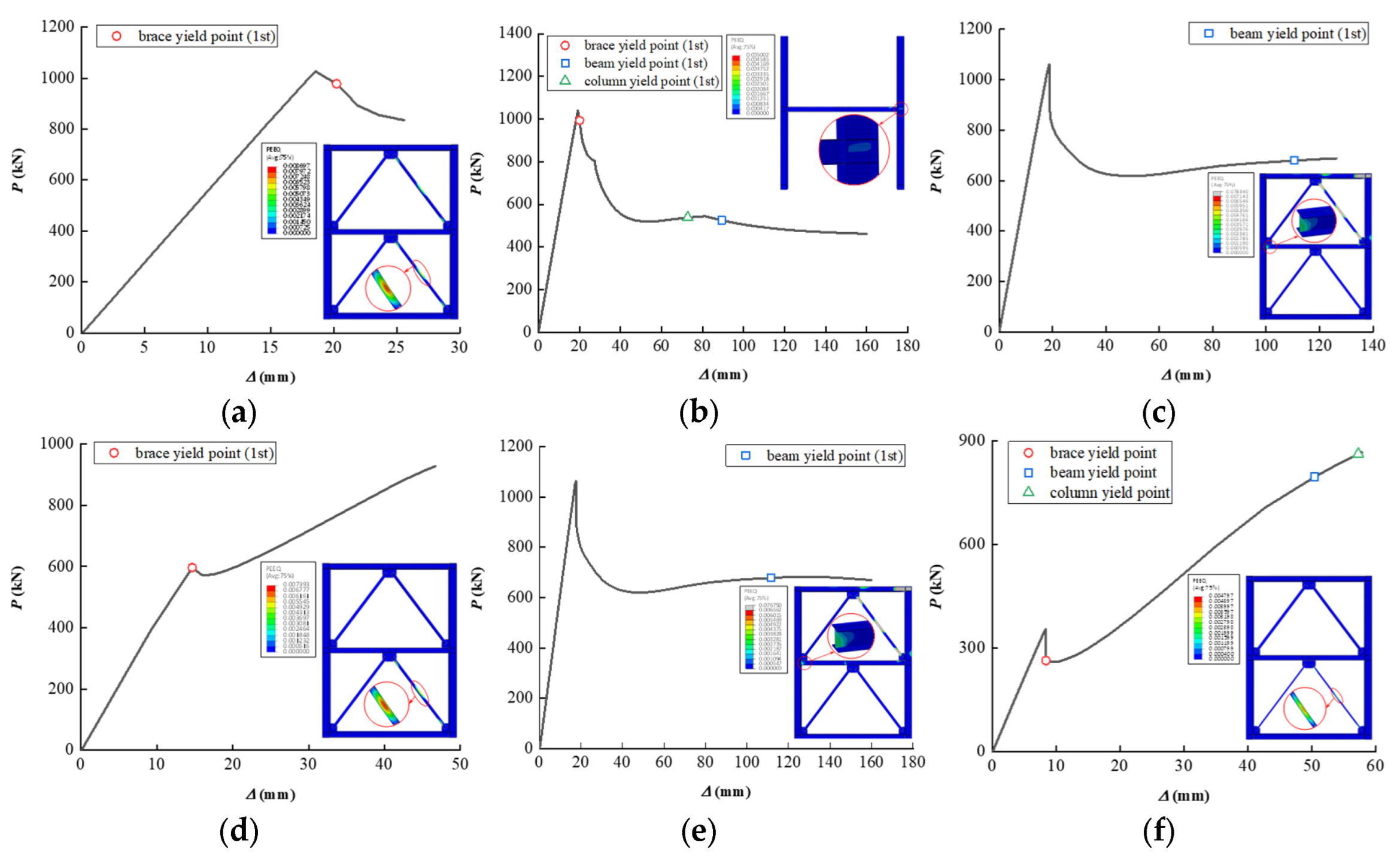
4.5. Top Floor Results
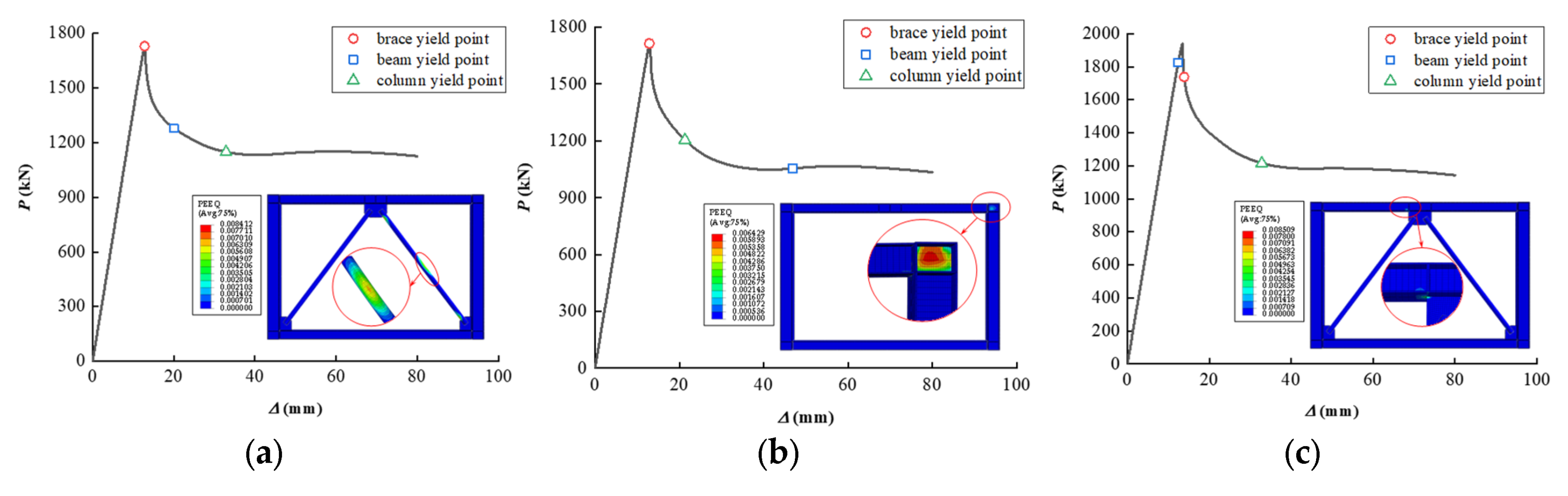
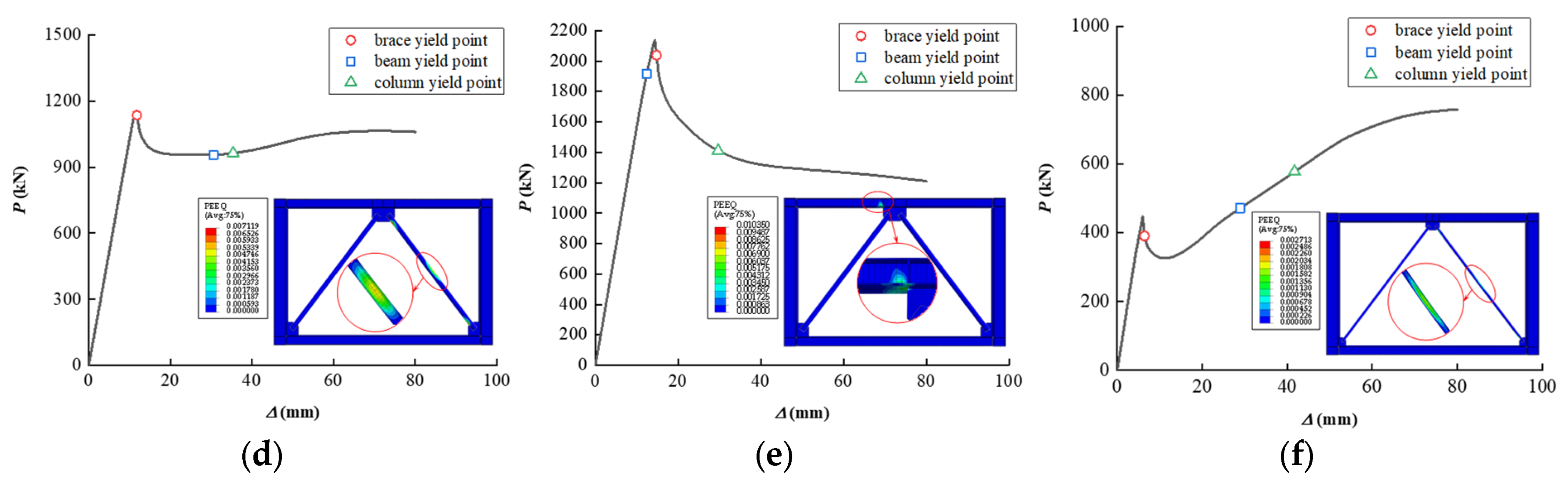
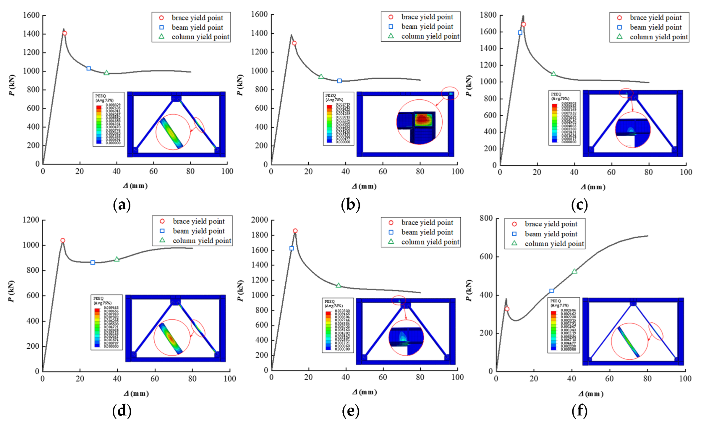
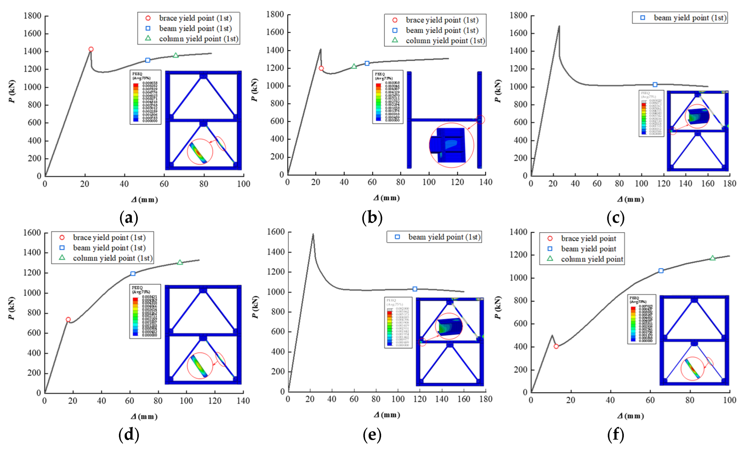
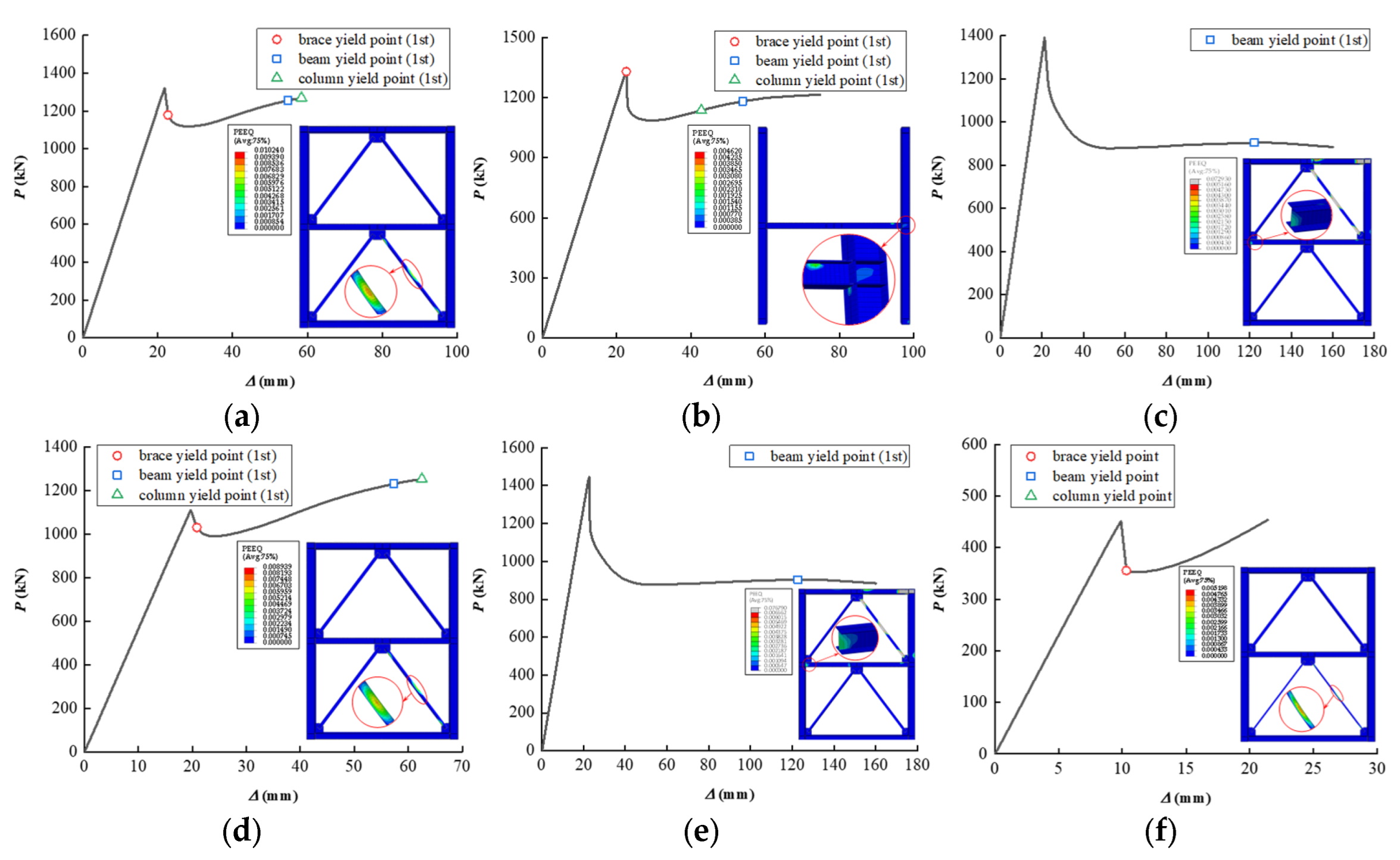
4.6. Typical Floor Results
5. Conclusions
- (1)
- The proposed method allows specifying the external diameter of the braces (D), their inner diameter (d), the web area of the columns (hcwtcw), and their flange thickness (wcf) based on given beam parameters. That should be useful in performance-based design.
- (2)
- Published experimental results and finite element modeling has demonstrated that the sequence of component yielding will follow the method’s predictions. The beam will yield first if the external or inner diameters of the braces are outside the ranges the method recommends. With a column web area smaller than the recommended minimum, the columns will yield first.
- (3)
- The axial compression in the braces significantly affects the yielding mechanism. The upper beam flange will be in a weak position under larger axial compression (η > 0.3). The beam ends and beam-brace connections should be stiffened to prevent local buckling.
- (4)
- The influence of stochastic variability in the parameters should be considered. Small changes in the parameters can change the structural yield sequence.
- (5)
- The proposed method helps to limit the initial feasible region in structure optimization. That will help to reduce convergence difficulties caused by the excessive size of the initial feasible region.
Author Contributions
Funding
Data Availability Statement
Conflicts of Interest
Nomenclature
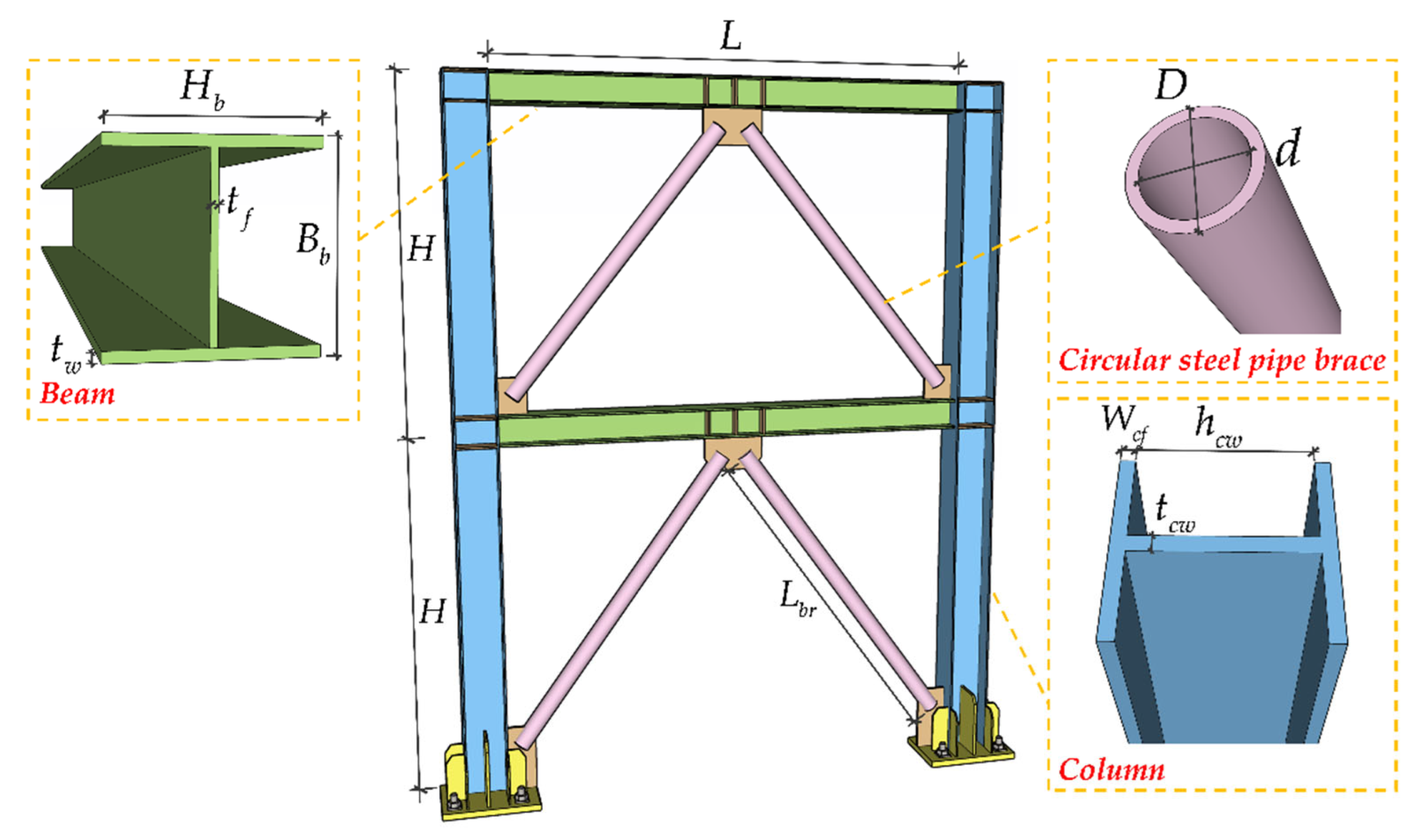
| d | inner diameter of a brace |
| D | external diameter of a brace |
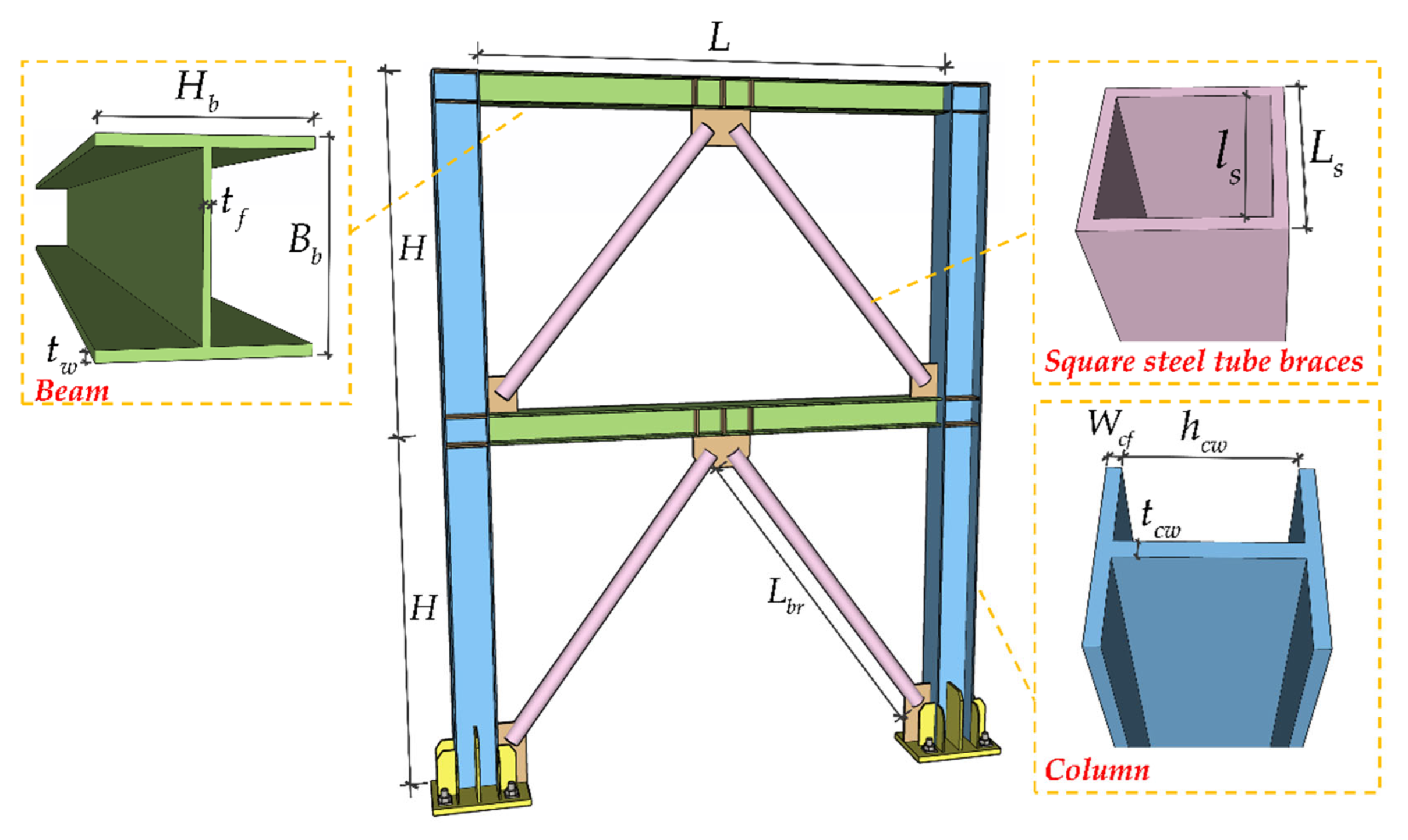
| wcf | width of the column’s flanges |
| hcwtcw | cross-sectional area of column’s webs |
| Mpb | beam’s plastic bending yield strength |
| Wpb | beam’s plastic section modulus |
| fy | steel’s yield strength |
| Mbry | brace’s bending yield strength |
| Mpbc | beam’s plastic yield strength with the influence of two brace (top floor) |
| Ab | beam’s cross-sectional area |
| L | beam’s length |
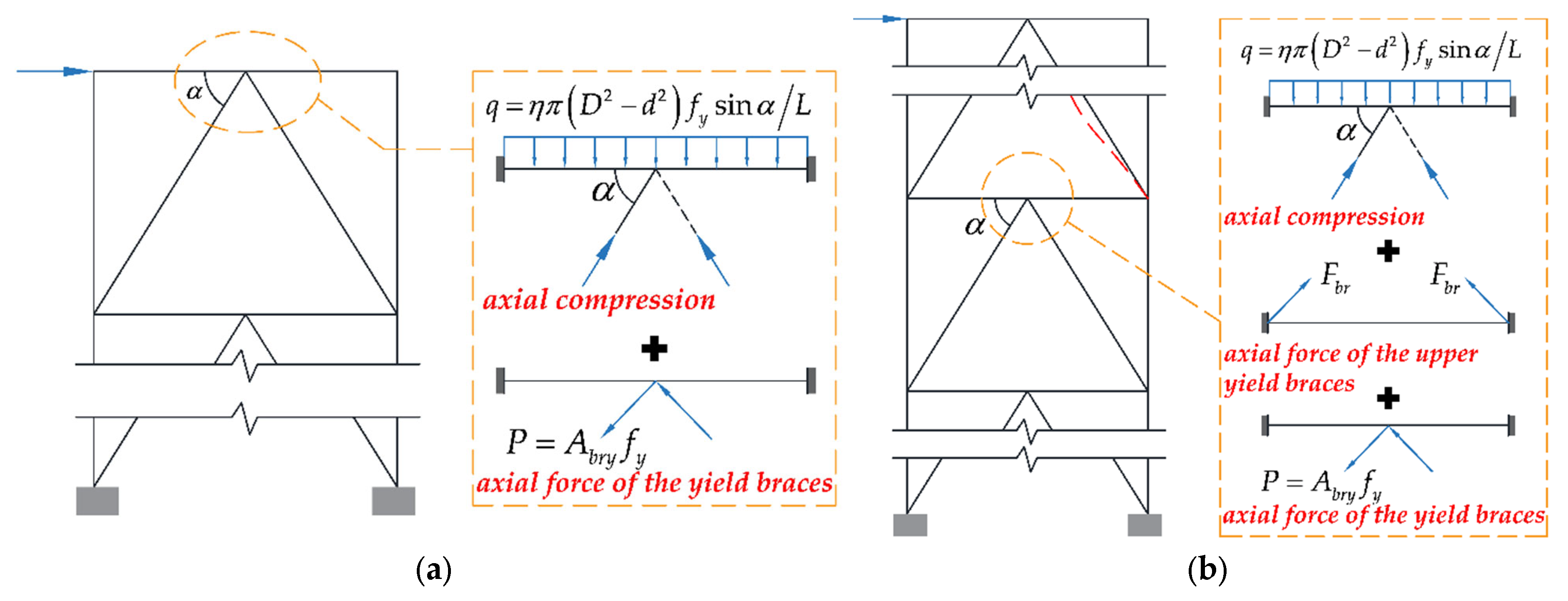
| P | axial force applied by (circular steel tube) braces when they yield |
| Abry | brace’s cross-sectional area |
| q | uniform load on the beam based on η |
| η | axial compression ratio of braces |
| α | angle between beam and brace. |
| M’pbc | beam’s plastic yield strength with the influence of four brace (typical floor) |
| Fbr | axial force applied by the upper braces at yielding |
| Mcy | bending yield strength of a column panel-zone |
| hbw | height of the beam’s web |
| hcw | height of the column’s web |
| tcw | thickness of the column’s web |
| λ | slenderness ratio of the braces |
| H | height of the structural floor |
| ls | inner length of square tubular brace |
| Ls | external length of square tubular brace |
| Lbr | brace’s length |
| Hb | beam’s height |
| Bb | beam’s width |
| tbw | beam’s web thickness |
| tfw | beam’s flange thickness |
| tbry | brace’s thickness |
Appendix A

| Case | Column Section (mm) | Brace Section (mm) | Proposed Method | FEM Result | |
|---|---|---|---|---|---|
| External Diameters (η 1) | Thickness (η 1) | ||||
| 13–15 | HW 350 × 350 × 19 × 19 | 140 (0.15, 0.2, 0.3) | 13 (0.15), 12 (0.2), 10 (0.3) | Brace Yielding | Brace Yielding |
| 16–18 | HW 344 × 348 × 10 × 16 | 140 (0.15, 0.2, 0.3) | 13 (0.15), 12 (0.2), 10 (0.3) | Column Yielding before the beam | Column Yielding before the beam |
| 19–21 | HW 350 × 350 × 19 × 19 | 140 (0.15, 0.2, 0.3) | 15 (0.15), 15 (0.2), 13 (0.3) | Beam Yielding | Beam Yielding |
| 22–24 | HW 350 × 350 × 19 × 19 | 140 (0.15, 0.2, 0.3) | 8 (0.15, 0.2, 0.3) | Brace Yielding | Brace Yielding |
| 25–27 | HW 350 × 350 × 19 × 19 | 146 (0.15, 0.2), 144 (0.3) | 16 (0.15), 15 (0.2), 12 (0.3) | Beam Yielding | Beam Yielding |
| 28–30 | HW 350 × 350 × 19 × 19 | 74 (0.15, 0.2, 0.3) | 13 (0.15), 12 (0.2), 10 (0.3) | Brace Yielding | Brace Yielding |


| Case | Column Section (mm) | Brace Section (mm) | Proposed Method | FEM Result | |
|---|---|---|---|---|---|
| External Diameters (η) | Thickness (η) | ||||
| 31–33 | HW 350 × 350 × 19 × 19 | 140 (0.2), 135 (0.15, 0.3) | 10.5 (0.15), 10 (0.2), 9.5 (0.3) | Brace Yielding | Brace Yielding |
| 34–36 | HW 344 × 348 × 10 × 16 | 140 (0.2), 135 (0.15, 0.3) | 10.5 (0.15), 10 (0.2), 9.5 (0.3) | Column Yielding before the beam | Column Yielding before the beam |
| 37–39 | HW 350 × 350 × 19 × 19 | 140 (0.2), 135 (0.15, 0.3) | 13.5 (0.15), 13 (0.2), 10.5 (0.3) | Beam Yielding | Beam Yielding |
| 40–42 | HW 350 × 350 × 19 × 19 | 140 (0, 0.2), 135 (0.15, 0.3) | 8 (0.2), 4.5 (0.15, 0.3) | Brace Yielding | Brace Yielding |
| 43–45 | HW 350 × 350 × 19 × 19 | 144 (0.15, 0.2), 142 (0.3) | 15 (0.15), 12 (0.2), 13 (0.3) | Beam Yielding | Beam Yielding |
| 46–48 | HW 350 × 350 × 19 × 19 | 74 (0.15, 0.2, 0.3) | 10.5 (0.15), 10 (0.2), 9.5 (0.3) | Brace Yielding | Brace Yielding |


References
- Costanzo, S.; Tartaglia, R.; Lorenzo, G.D.; Martino, A.D. Seismic Behaviour of EC8-Compliant Moment Resisting and Concentrically Braced Frames. Buildings 2021, 9, 196. [Google Scholar] [CrossRef] [Green Version]
- Anonymous. Code for Seismic Design of Buildings; China Architecture & Building Press: Beijing, China, 2010. [Google Scholar]
- Anonymous. Standard for Design of Steel Structures; China Architecture & Building Press: Beijing, China, 2017. [Google Scholar]
- Anonymous. Eurocode 8: Design of Structure for Earthquake Resistance; British Standards Institution: London, UK, 2005. [Google Scholar]
- Anonymous. Seismic Provision of Structural Steel Buildings; American Institute of Steel Construction: Chicago, IL, USA, 2016. [Google Scholar]
- Tong, G.S.; Mi, X.F. Aseismic Behavior of Multistory Frames Based on Different Braces Design Methods. Eng. Mech. 2008, 25, 107–115. [Google Scholar]
- Kumar, P.C.A.; Sahoo, D.R. Optimum Range of Slenderness Ratio of Hollow Steel Square Braces for Special Concentrically Braced Frames. Adv. Struct. Eng. 2016, 19, 928–944. [Google Scholar] [CrossRef]
- Naderpour, M.N.; Aghakouchak, A.A. Probabilistic Damage Assessment of Concentrically Braced Frames with Built Up Braces. J. Construct. Steel Res. 2018, 147, 191–202. [Google Scholar] [CrossRef]
- Kumar, P.C.A.; Sahoo, D.R. Fracture Ductility of Hollow Circular and Square Steel Braces under Cyclic Loading. Thin-Wall Struct. 2018, 130, 347–361. [Google Scholar] [CrossRef]
- Sen, A.D.; Sloat, D.; Ballard, R.; Johnson, M.M.; Roeder, C.W.; Lehman, D.E.; Berman, J.W. Experimental Investigation of Chevron Concentrically Braced Frames with Yielding Beams. J. Struct. Eng. 2016, 142, 04016123. [Google Scholar] [CrossRef]
- Leelataviwat, S.; Goel, S.C.; Stojadinovic, B. Energy-Based Seismic Design of Structures Using Yield Mechanism and Target Drift. J. Struct. Eng. 2002, 128, 1046. [Google Scholar] [CrossRef]
- Sepahvand, M.F.; Akbari, J.; Kusunoki, K. Plastic Design of moment resisting frames using mechanism control. J. Constr. Steel Res. 2019, 153, 275–285. [Google Scholar] [CrossRef]
- Sepahvand, M.F.; Akbari, J.; Kusunoki, K. Optimum Plastic Design of Moment Resisting Frames Using Mechanism Control. Structures 2018, 16, 254–268. [Google Scholar] [CrossRef]
- Sepahvand, M.F.; Akbari, J. Toward Seismic Design of Tall Steel Moment Resisting Frames Using the Theory of Plastic Mechanism Control. J. Build. Eng. 2018, 24, 100705. [Google Scholar] [CrossRef]
- Bai, J.L.; Ou, J.P. Seismic Plastic Limit-state Design of Frame Structures Based on the Strong-column Weak-beam Failure Mechanism. In Proceedings of the 15-WCEE, Lisbon, Portugal, 24–28 September 2012. [Google Scholar]
- Mastrandrea, L.; Piluso, V. Plastic Design of Eccentrically Braced Frames, II: Failure Mode Control. J. Constr. Steel Res. 2008, 65, 1015–1028. [Google Scholar] [CrossRef]
- Longo, A.; Montuori, R.; Piluso, V. Failure Mode Control of X-braced Frames Under Seismic Actions. J. Earthq. Eng. 2008, 12, 728–759. [Google Scholar] [CrossRef]
- Longo, A.; Montuori, R.; Piluso, V. Plastic Design of Seismic Resistant V-braced Frames. J. Earthq. Eng. 2008, 12, 1246–1266. [Google Scholar] [CrossRef]
- Mazzolani, M.F.; Piluso, V. Plastic Design of Seismic Resistant Steel Frames. Earthq. Eng. Struct. Dyn. 1997, 26, 167–191. [Google Scholar] [CrossRef]
- Roeder, C.W.; Lehman, D.E.; Yoo, J.H. Improved Seismic Design of Steel Frame Connections. Int. J. Steel Struct. 2005, 5, 141–153. [Google Scholar]
- Yang, R.Q.; Zhou, X.J. Low-cyclic Reversed Loading Tests of Chevron Concentrically Braced Steel Frames with Semi-rigid Connections of Different Details. Prog. Steel Build. Struct. 2021, 23, 75–84. [Google Scholar] [CrossRef]
- Lai, J.W. Experimental and Analytical Studies on the Seismic Behavior of Conventional and Hybrid Braced Frames. Ph.D. Thesis, University of California, Berkeley, CA, USA, 2012. [Google Scholar]
- Roeder, C.W.; Sen, A.D.; Terpstra, C.; Ibarra, S.M.; Liu, R.Y.; Lehman, D.E.; Berman, J.W. Effect of Beam Yielding on Chevron Braced Frames. J. Constr. Steel Res. 2019, 159, 428–441. [Google Scholar] [CrossRef]
- Xu, J.; Wang, Z.; Wang, P.; Pan, J.R.; Li, B. Numerical Investigations on Large Size Stiffened Angle Connections with Different Bolt Patterns. J. Construct. Steel Res. 2021, 182, 106670. [Google Scholar] [CrossRef]
- Yang, J.F.; Gu, Q.; Wan, H.; Peng, Y.L. Research on Pushover Test of Inverted-V Concentrically Braced Steel Frame. J. Xi’an Univ. Archit. Technol. Nat. Sci. Ed. 2010, 5, 656–662. [Google Scholar] [CrossRef]


| References and Specifications | Suggestions on Structural Yield Mechanism Control |
|---|---|
| GB 50017 [2] | Braces yield before beams and columns yield |
| GB 50011 [3] | The beams remain elastic when braces yield |
| AISC-341 [4] | The braces should yield first |
| EC8 [5] | The bearing capacity of beams and columns after the braces yield should be checked |
| Roeder, Lehman & Yoo [20] | The energy dissipation capacity of the braces should be fully utilized to ensure that the braces yield before the beams and column |
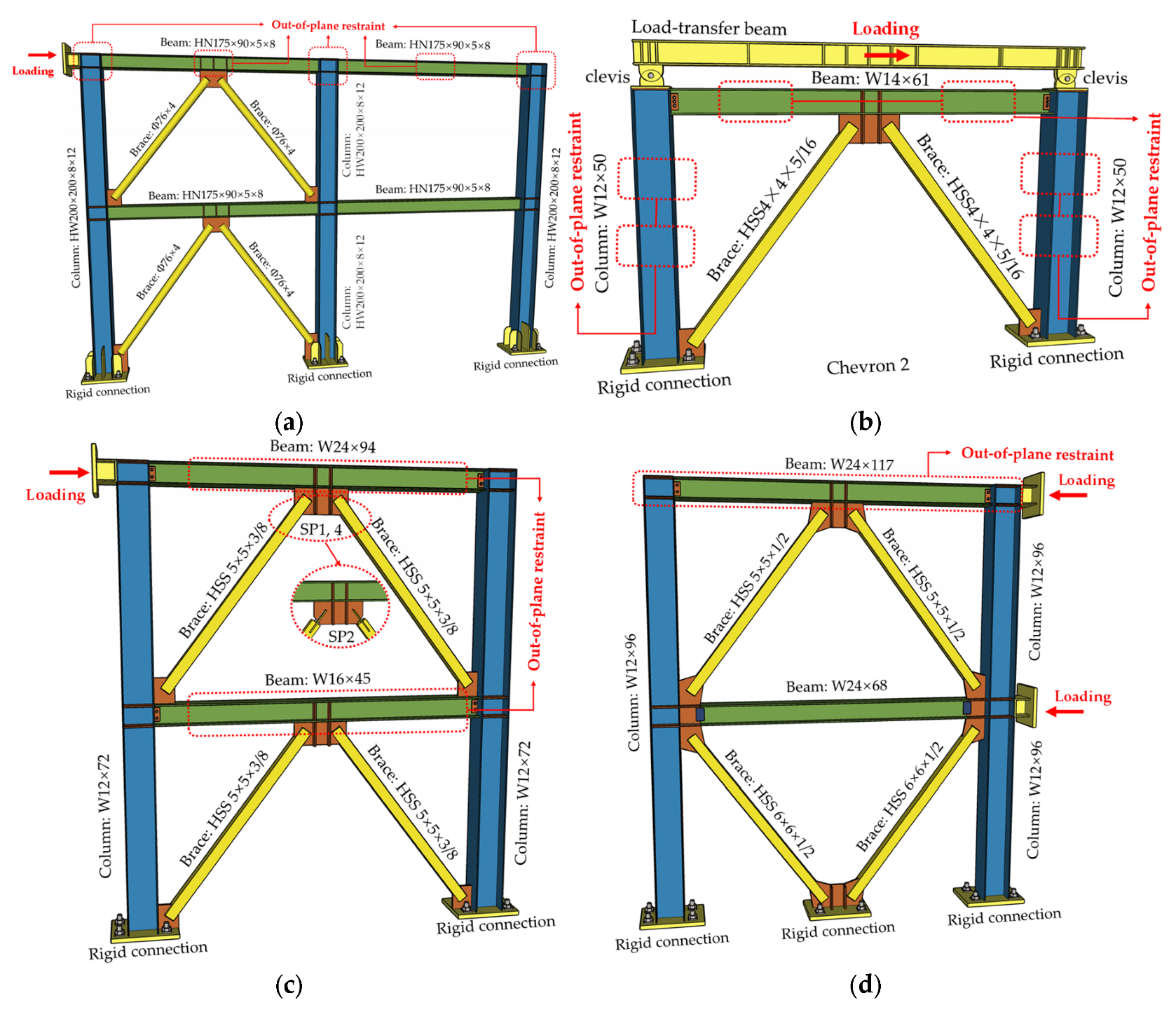
| Specimen ID | Beam (mm or in) | Column Constraint | Brace Constraint (mm) | Test Result | Proposed Method | ||||
|---|---|---|---|---|---|---|---|---|---|
| Column (mm or in) | Web Constraint (mm2) | Flange Constraint (mm) | Brace (mm or in) | External Diameters Constraint | Inner Diameters Constraint | ||||
| SCBF-1 [21] | HN175 × 90 × 5 × 8 | HW200 × 200 × 8 × 12 | hcwtcw > 1095 | wcf > 90 | Φ76 × 4 | 61 < D < 122 | 66 < d < 93 | Brace Yielding | Brace Yielding |
| TCBF-B-2 [22] | W24 × 117 1 | W12 × 961 | hcwtcw > 10708 | wcf > 325 | HSS5 × 5 × ½ 1 | 61 < Ls < 129 | 87 < ls < 91 | Brace Yielding | Brace Yielding |
| SP1 [10] | W24 × 94 | W12 × 72 | hcwtcw > 8164 | wcf > 230 | HSS5 × 5 × 3/8 | 63 < Ls < 131 | 87 < ls < 95 | Brace Yielding | Brace Yielding |
| Chevron 2 [23] | W14 × 61 | W12 × 50 | hcwtcw > 6017 | wcf > 254 | HSS4 × 4 × 5/16 | 61 < Ls < 127 | 61 < ls < 93 | Brace Yielding | Brace Yielding |
| Chevron 3 [23] | W14 × 38 | W12 × 50 | hcwtcw > 3452 | wcf > 172 | HSS4 × 4 × 5/16 | 58 < Ls < 116 | 72 < ls < 94 | Brace Yielding | Brace Yielding |
| Chevron 4 [23] | W14 × 26 | W12 × 50 | hcwtcw > 2209 | wcf > 128 | HSS4 × 4 × 5/16 | 58 < Ls < 112 | 82 < ls < 94 | Brace Yielding | Brace Yielding |
| Chevron 6 [23] | W21 × 44 | W12 × 50 | hcwtcw > 3377 | wcf > 165 | HSS4 × 4 × 5/16 | 61 < Ls < 122 | 66 < ls < 93 | Brace Yielding | Brace Yielding |
| Specimen ID | Upper Brace (mm or in) | Beam (mm or in) | Column Constraint | Brace Constraint (mm) | Test Result | Proposed Method | ||||
|---|---|---|---|---|---|---|---|---|---|---|
| Column (mm or in) | Web Constraint (mm2) | Flange Constraint (mm) | Brace (mm or in) | External Diameters Constraint | Inner Diameters Constraint | |||||
| SCBF-2 [21] | Φ76 × 4 | HN175 × 90 × 5 × 8 | HW200 × 200 × 8 × 12 | hcwtcw > 1095 | wcf > 90 | Φ76 × 4 | 53 < D < 98 | 65 < d < 72 | Brace Yielding | Brace Yielding |
| SP2 [10] | HSS7 × 7 × 1/4 | W16 × 45 | W12 × 72 | hcwtcw > 4009 | wcf > 179 | HSS5 × 5 × 3/8 | 63 < Ls < 121 | 102 < ls < 103 | Brace Yielding | Brace Yielding |
| SP4 [10] | HSS5 × 5 × 3/8 | W16 × 45 | W12 × 72 | hcwtcw > 4009 | wcf > 179 | HSS5 × 5 × 3/8 | 63 < Ls < 121 | 102 < ls < 103 | Brace Yielding | Brace Yielding |
| Chevron R [23] | HSS8 × 8 × 1/4 | W12 × 40 | W12 × 53 | hcwtcw > 3875 | wcf > 203 | HSS8 × 8 × 3/8 | 91 < Ls < 124 | 112 < ls < 113 | Beam Yielding | Beam Yielding |
| Case | Column Section (mm) | Brace Section (mm) | Proposed Method | FEM Result | |
|---|---|---|---|---|---|
| External Diameters | Thickness | ||||
| 1 | HW 350 × 350 × 19 × 19 | 140 | 15 | Brace Yielding | Brace Yielding |
| 2 | HW 344 × 348 × 10 × 16 | 140 | 15 | Column Yielding before the beam | Column Yielding before the beam |
| 3 | HW 350 × 350 × 19 × 19 | 140 | 20 | Beam Yielding | Beam Yielding |
| 4 | HW 350 × 350 × 19 × 19 | 140 | 8 | Brace Yielding | Brace Yielding |
| 5 | HW 350 × 350 × 19 × 19 | 150 | 20 | Beam Yielding | Beam Yielding |
| 6 | HW 350 × 350 × 19 × 19 | 74 | 15 | Brace Yielding | Brace Yielding |
| Case | Column Section (mm) | Brace Section (mm) | Proposed Method | FEM Result | |
|---|---|---|---|---|---|
| External Diameters | Thickness | ||||
| 7 | HW 350 × 350 × 19 × 19 | 140 | 12 | Brace Yielding | Brace Yielding |
| 8 | HW 344 × 348 × 10 × 16 | 140 | 12 | Column Yielding before the beam | Column Yielding before the beam |
| 9 | HW 350 × 350 × 19 × 19 | 140 | 14 | Beam Yielding | Beam Yielding |
| 10 | HW 350 × 350 × 19 × 19 | 140 | 8 | Brace Yielding | Brace Yielding |
| 11 | HW 350 × 350 × 19 × 19 | 144 | 14 | Beam Yielding | Beam Yielding |
| 12 | HW 350 × 350 × 19 × 19 | 74 | 12 | Brace Yielding | Brace Yielding |
Publisher’s Note: MDPI stays neutral with regard to jurisdictional claims in published maps and institutional affiliations. |
© 2022 by the authors. Licensee MDPI, Basel, Switzerland. This article is an open access article distributed under the terms and conditions of the Creative Commons Attribution (CC BY) license (https://creativecommons.org/licenses/by/4.0/).
Share and Cite
Li, B.; Wang, Z.; Fan, Y.; Pan, J.; Wang, P.; Zhou, Z. A Technique for Optimizing the Sequences Yielding under Load of Concentrically-Braced Steel Frames. Buildings 2022, 12, 1656. https://doi.org/10.3390/buildings12101656
Li B, Wang Z, Fan Y, Pan J, Wang P, Zhou Z. A Technique for Optimizing the Sequences Yielding under Load of Concentrically-Braced Steel Frames. Buildings. 2022; 12(10):1656. https://doi.org/10.3390/buildings12101656
Chicago/Turabian StyleLi, Bin, Zhan Wang, Yanjing Fan, Jianrong Pan, Peng Wang, and Zhenfeng Zhou. 2022. "A Technique for Optimizing the Sequences Yielding under Load of Concentrically-Braced Steel Frames" Buildings 12, no. 10: 1656. https://doi.org/10.3390/buildings12101656