Article

Seismic Fragility Analysis of Low-Rise RC Buildings with Brick Infills in High Seismic Region with Alluvial Deposits

1
Department of Civil Engineering, Cosmos College of Management and Technology, Lalitpur 44600, Nepal
2
Interdisciplinary Research Institute for Sustainability (IRIS), Kathmandu 44601, Nepal
3
Department of Civil Engineering, Institute of Engineering, Pulchowk Campus, Lalitpur 44600, Nepal
4
Earthquake Engineering Research Center, Faculty of Civil and Environmental Engineering, University of Iceland, Austurvegur 2a, 800 Selfoss, Iceland
5
Department of Civil Engineering, Institute of Engineering, Thapathali Campus, Kathmandu 44601, Nepal
6
Nepal Academy of Science and Technology, Lalitpur 44600, Nepal
*
Authors to whom correspondence should be addressed.
Buildings 2022, 12(1), 72; https://doi.org/10.3390/buildings12010072
Submission received: 9 November 2021 / Revised: 5 January 2022 / Accepted: 11 January 2022 / Published: 12 January 2022
(This article belongs to the Special Issue Seismic Performance of New-Designed and Existing RC Buildings)

Abstract

:
Most of the reinforced concrete buildings in Nepal are low-rise construction, as this type of construction is the most dominant structural form adopted to construct residential buildings in urban and semi-urban neighborhoods throughout the country. The low-rise residential constructions generally follow the guidelines recommended by the Nepal Building Code, especially the mandatory rules of thumb. Although low-rise buildings have brick infills and are randomly constructed, infill walls and soil–structure interaction effects are generally neglected in the design and assessment of such structures. To this end, bare frame models that are used to represent such structures are questionable, especially when seismic vulnerability analysis is concerned. To fulfil this gap, we performed seismic vulnerability analysis of low-rise residential RC buildings considering infill walls and soil–structure interaction effects. Considering four analysis cases, we outline comparative seismic vulnerability for various analysis cases in terms of fragility functions. The sum of observations highlights that the effects of infills, and soil–structure interaction are damage state sensitive for low-rise RC buildings. Meanwhile, the design considerations will be significantly affected since some performance parameters are more sensitive than the overall fragility. We also observed that the analytical fragility models fundamentally overestimate the actual seismic fragility in the case of low-rise RC buildings.

1. Introduction

Structural response is fundamentally a function of response of superstructure, substructure (foundation), and soil underlying the foundation. Thus, performance of a building under earthquake excitation is attributed not only to the physical vulnerabilities of structural and nonstructural components, but also the soil foundation structure interaction. Many moderate to strong earthquakes that hit various parts of the world have exposed seismically vulnerable aspects of reinforced concrete buildings (see e.g., [1,2,3,4,5,6,7,8]). Many residential RC buildings are designed considering the foundation as rigid, even in areas with soft soil deposits, thus neglecting the effect of soil–structure interaction. Fixed-based foundation assumption may not be so important for low-rise buildings resting in relatively stiff soil, but for medium and high-rise buildings constructed on soft soil, effect of soil behavior can alter their seismic performance to a large extent [9].
Brick infills are widely used in RC buildings. While they might provide considerable stiffness during lateral shaking, it is customary in design practice to ignore their stiffness contribution. They are accounted for in structural analysis and design mainly for the dead loads they impose on the structural frames. Brick infill walls in RC framed structures are known to cause an important role in seismic damage [2,4,5,8,10]. Their effect on stiffness and strength of RC framed buildings is well documented in the literature (see e.g., [11,12,13,14]). Effects of masonry infill walls on overall performance of buildings have been studied using analytical [15,16,17] and experimental [18,19,20,21] methods. While well-distributed infill walls are known to reduce inter-story drift demands, irregular distribution is known to cause undesirable mechanisms such as soft story failure [22], short-column damage, etc. Pujol and Fick [21] report that stiff infills can cause brittle failure of columns in RC frames. Infills can provide stiffness against lateral drift, which can be effective under moderate shaking. Due to their inherent lack of strength and ductility, they crack under strong shaking and cause undesirable transfer of forces to the RC frames. Effect of infill walls in overall seismic performance can therefore be both positive and negative, depending on several factors, and a subject that needs to be better understood.
Some remarkable cases of infill damage were observed during the 2015 Gorkha and 2016 Central Italy earthquakes [23,24]. Out-of-plane collapse of infill walls is one of the most dangerous failure modes that possess great risk to occupants.
Soil–structure interaction effects can be categorized as inertial and kinematic interactions [25]. Inertial effects occur mainly due to flexibility in the soil foundation system, which gets deformed due to inertial forces exerted by the structure. The overall effect is a more flexible (than a fixed based) system. Kinematic interactions arise due to the stiffness of the foundation, which interferes with the motion of the surrounding soil and result in differences between foundation input and free-field ground motions. Incoherent shaking across the foundation slab and variation of shaking at different depths of foundation are typical consequences of kinematic interactions. The difference between the flexible and rigid base systems in the foundation soil has been widely studied using shake table experiments (see e.g., [26]). Mylonakis and Gazetas [27] discussed the beneficial and detrimental effect of soil–structure interaction on structures. Past records show that the increase in flexibility of structure increases the fundamental vibration period of the building. As a result, base shear decreases and on the other hand displacement demands increase. The decrease in base shear may be advantageous but the increase in displacement can lead to damage in the structural elements as well as potential pounding with adjacent structures. However, several other studies have pointed out that increase in vibration period and effective damping due to soil–structure interaction may not always reduce story shear forces [28,29]. In some contexts, especially in soft soil sites, soil–structure interaction may have harmful effects on the seismic performance of structures. Studies by Mylonakis and Gazetas [27] and Jie et al. [30] highlight both beneficial and adverse effects of soil–structure interaction. Soil–structure interaction effect is accounted for, albeit in different ways, in seismic design codes. The Eurocode-8 [31] acknowledges increase in the fundamental period of vibration and overall damping in structures resting on soft soil compared to those built on rock. Site effects are, however, accounted for mostly by increasing the design forces, which is meant to amplify peak ground acceleration depending on the stiffness of the underlying soil. Similarly, the ASCE/SEI 7-10 [32] provides mathematical formulations that focus on the design earthquake forces and corresponding displacements of the structure due to soil–structure interaction. The IS code 1893-2016 [33] and NBC 105:2020 [34] also highlight the effects of soil–structure interaction. Both codes suggest that the structure built on rigid base does not require consideration of soil–structure interaction (SSI). However, structures resting on soft soil site are required to be designed considering the effects of SSI. It is pertinent to note that most design codes follow an over-simplified approach to addressing the SSI problem. Effects of infill walls and SSI on overall seismic performance of structures therefore need further investigation and understanding for them to be adequately incorporated in design codes.
The main aim of this study is to shed light on effect of SSI and brick masonry in seismic performance of RC buildings with brick infill walls built on soft soil. A typical three storied RC framed structure in the Kathmandu Valley is used as a case study. Although some studies on seismic performance of such structures have been reported in the literature (see e.g., [7,24,35]), incorporation of both SSI and brick infill walls, and their effects on seismic fragility is missing. Analytical models of the SSI system are used in estimating seismic fragility, which is compared with empirically observed fragilities of similar buildings.

2. Materials and Methods

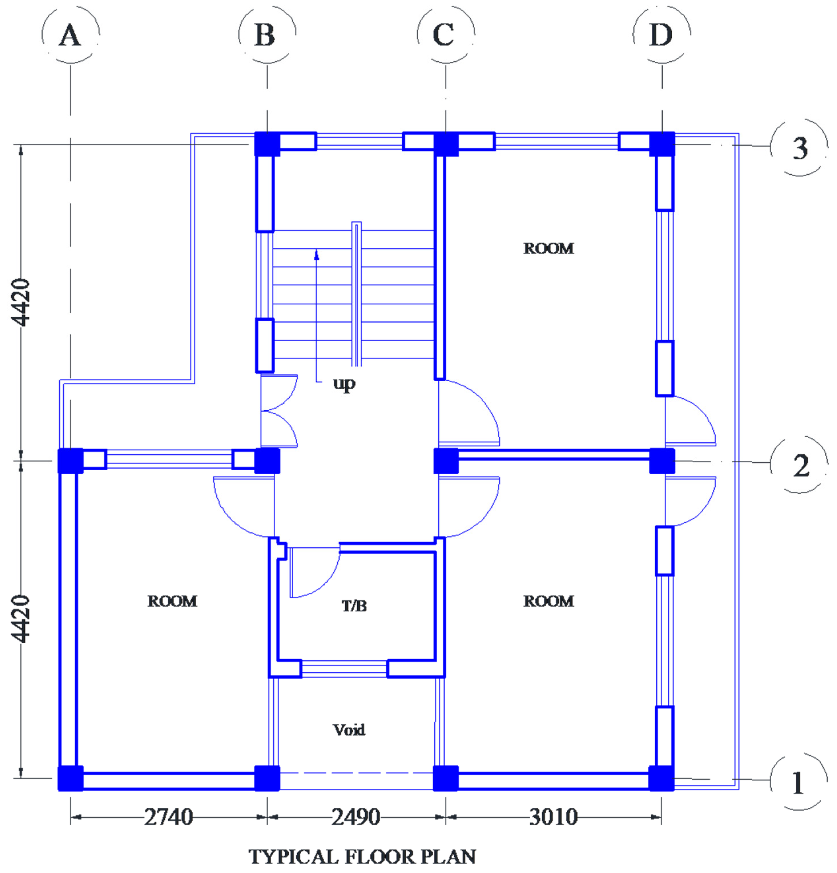
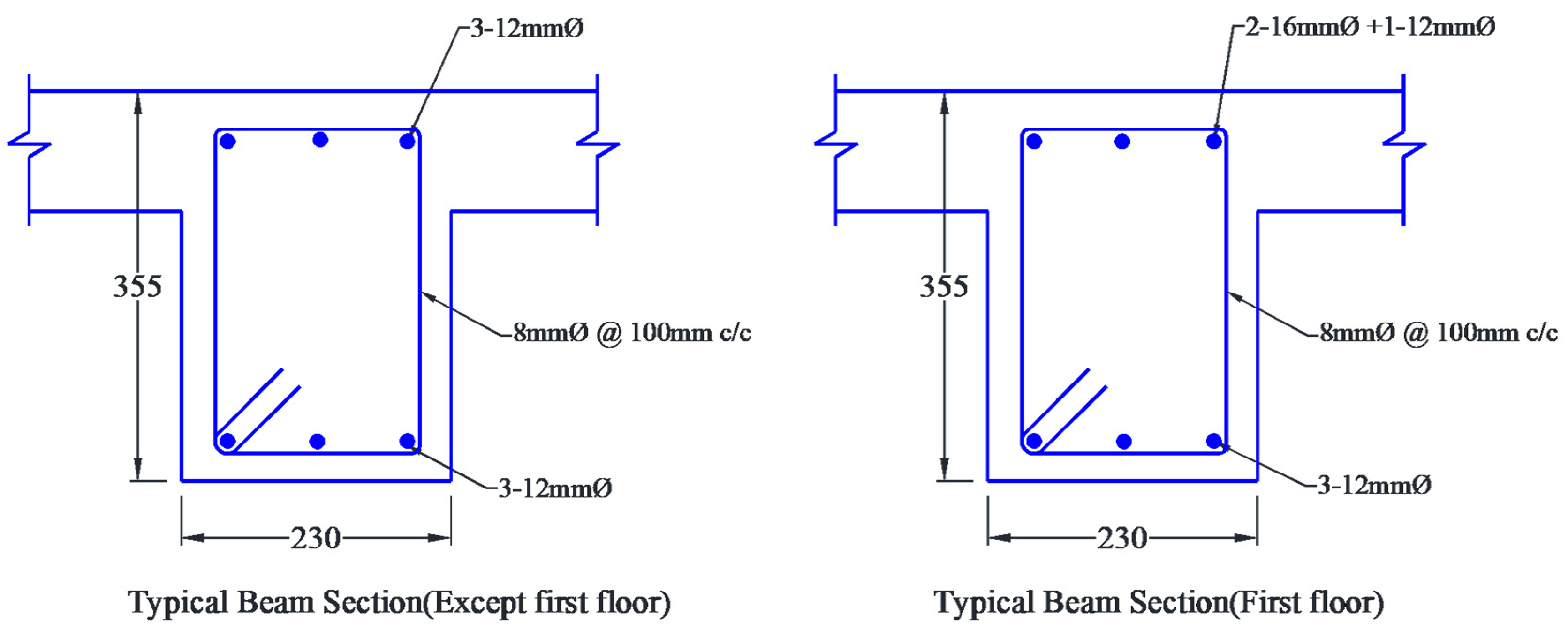
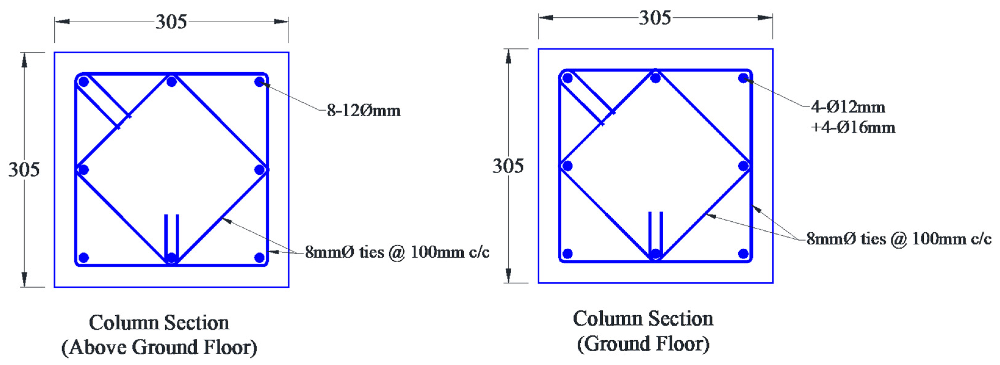
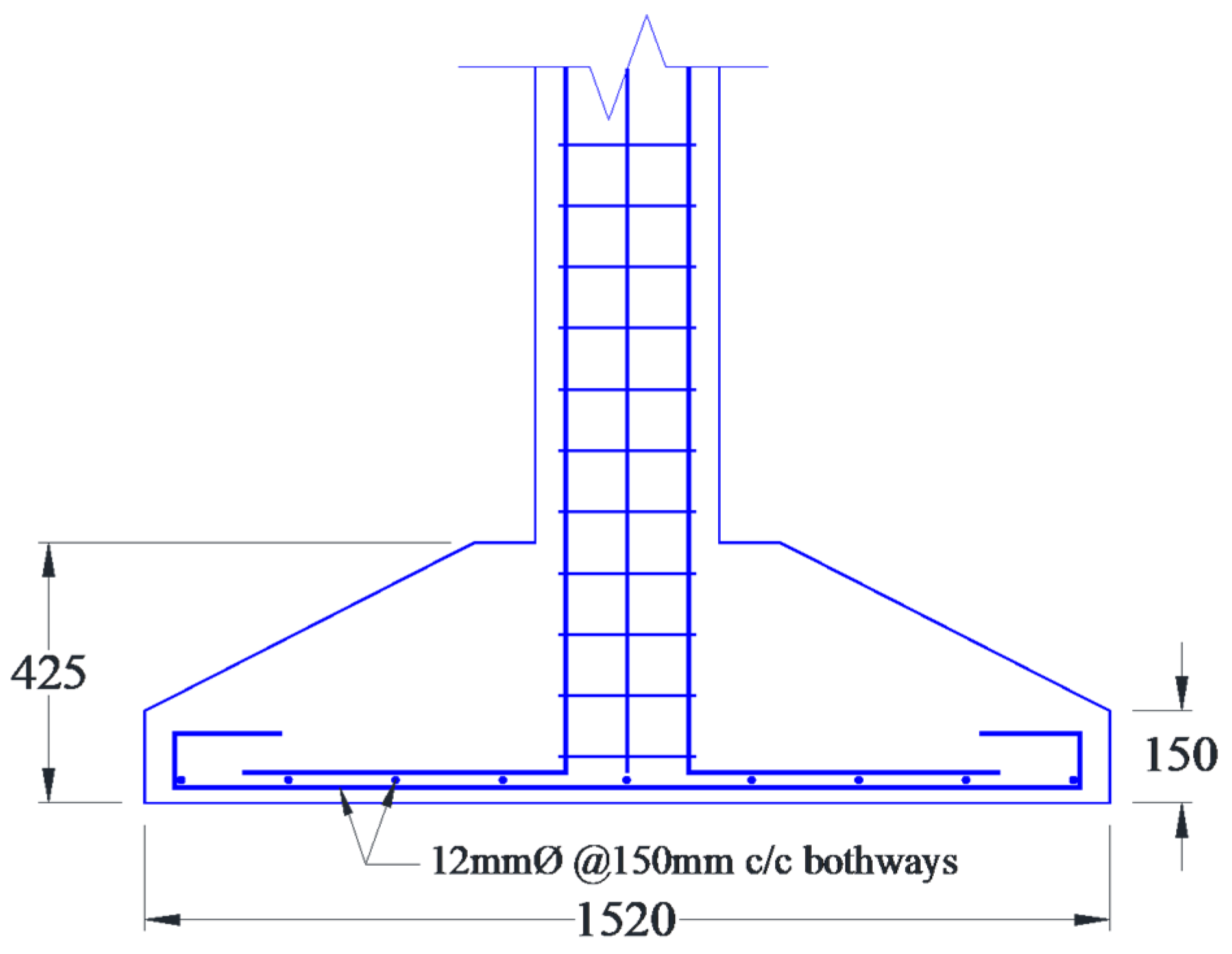
2.1. Case Study Building

Although, the NBC-205 guideline is not intended for irregular buildings, low-rise RC residential buildings often adopt structural sizing from it. Using fewer reinforcement bars than required by the code, RC buildings that are constructed using mandatory rules of thumb are commonly non-compliant to the code. We selected one such representative residential RC frame building as shown in Figure 1. The sectional details of beam, column, and foundation are respectively presented in Figure 2, Figure 3 and Figure 4. The geometrical and material properties of the case study building are summarized in Table 1.

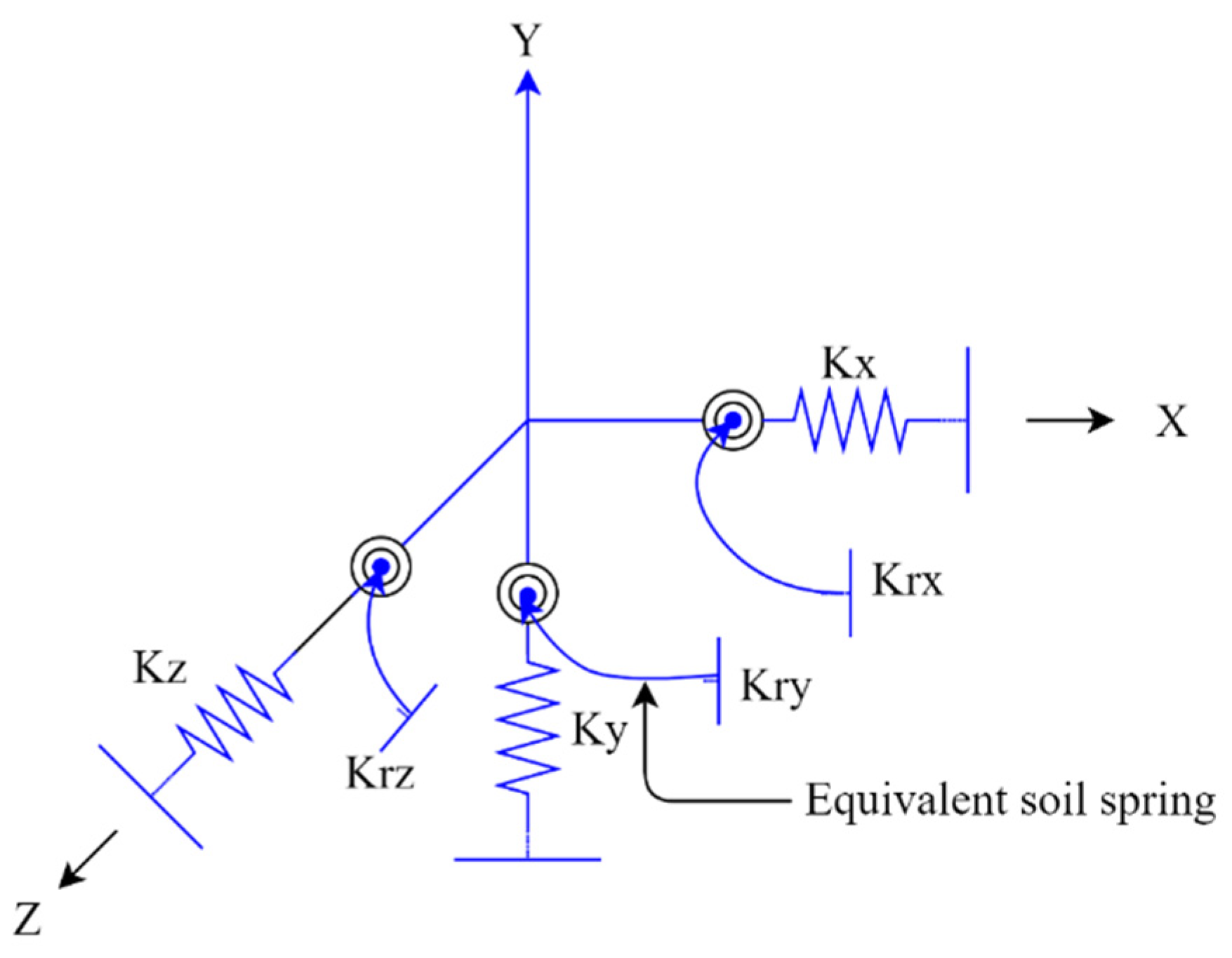
2.2. Soil–Structure Interaction Modeling

Since the case study building is situated on soft soil deposit at the northwestern fringe of Kathmandu Valley, soil parameters were collected from a nearby site. The uncorrected SPT-N value was converted to shear wave velocity using the empirical correlation proposed by Gautam [36]. Soil flexibility is modeled with equivalent springs with six degrees of freedom as shown in Figure 5 at each footing. Mechanical properties of the springs are based on formulations presented by Gazetas [37]. The shear wave velocity for the site was estimated to be 100 m/s and mass density of the soil was adopted as 13,500 Kg/m3. Meanwhile, Poisson’s ratio and modulus of rigidity of the underlying soil were respectively adopted as 0.4 and 13,500 KN/m2.
In Figure 5, Kx, Ky, and Kz are the equivalent spring stiffnesses along the translational DOF (along x, y, and z axes) and Krx, Kry, and Krz are the equivalent spring stiffnesses along the rotational DOF (along x, y, and z axes). Kx, and Kz were estimated to be 136,419 KN/m, while Ky is calculated to be 154,410 KN/m. Similarly, Krx and Krz were calculated to be 226,321 KN-m/rad, while Kry was estimated as 3,243,045 KN-m/rad.

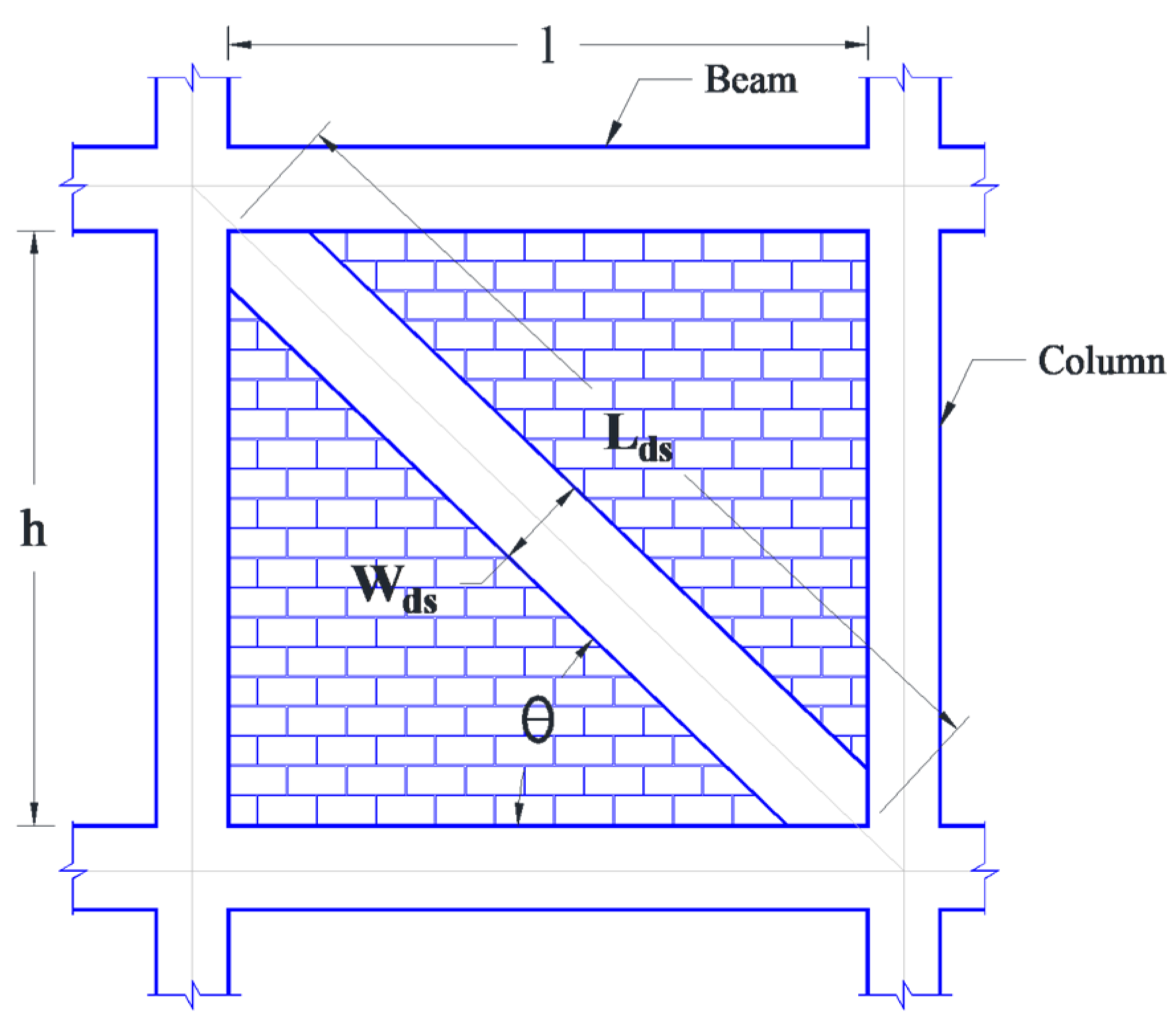
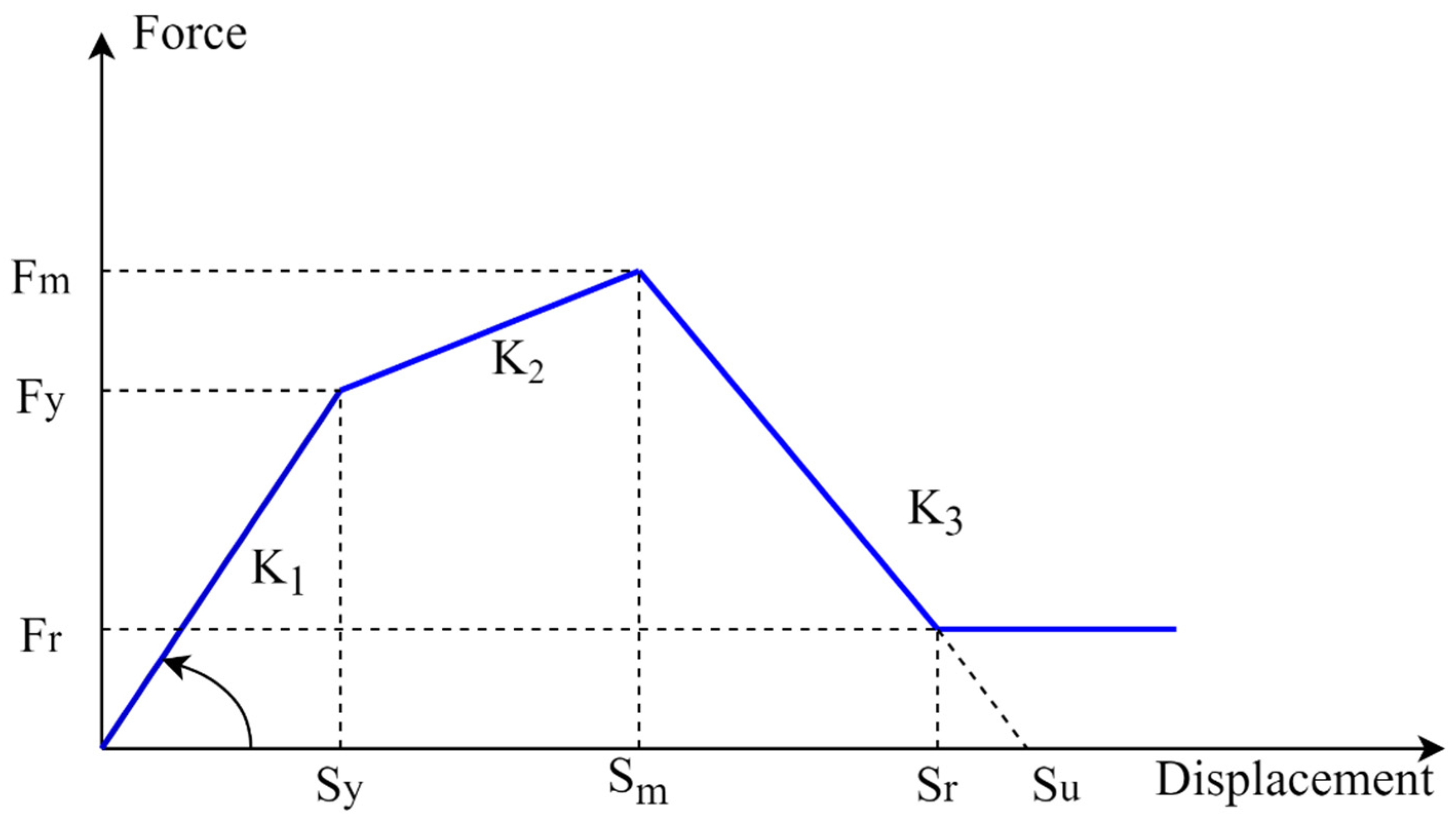
2.3. Infill Panel Modeling

Masonry infill wall is a composite material made up of brick, and mortar joints. The material and geometric properties of the infill walls vary to a large extent in practical applications. Nowadays, two finite element modeling techniques: (a) micro-models (plane finite element) and (b) macro model (equivalent strut model) are widely adopted for numerical analysis of infill walls. The first method is based on continuum theory, which provides accurate results of both material and geometric aspects of masonry infill panels. On the other hand, macro models use equivalent diagonal struts. Thus, due to simplicity in modeling, the macro-model is used in this study. The main disadvantage of the macro model method lies in modeling the openings, but some approaches that consider the effect of openings exist in the literature (e.g., [38,39]). To model the brick infills, we considered brick units with 18 KN/m3 unit weight, 7.5 MPa compressive strength, and 1:6 cement-sand mortar. The FEMA 306 [40] and IS 1893-2016 [33] recommend Equation (1) to model the masonry infill panel using the equivalent diagonal compression strut of width Wds (Figure 6). Unreinforced masonry infill walls without any opening width of equivalent diagonal strut is given by:
W d s = 0.175 α h 0.4 L d s
where, α h = h × ( E m   t   s i n 2 θ 4   E t   I c   h 4 ) , E m is the modulus of elasticity of the material of the infill wall, E t is the elastic modulus of the RC moment resisting frame, I c is the moment of inertia of the adjoining column, t is the thickness of the infill wall, and θ is the angle of the diagonal strut with the horizontal. The length of the equivalent diagonal strut (Lds) is given as
L d s = ( ( l e n g t h   o f   i n f i l l   w a l l ) 2 + ( c l e a r   h e i g h t   o f   t h e   c o l u m n ) 2 .
The modulus of the elasticity of the masonry infill wall was taken as:
E m = 550   f m
where, the compressive strength of masonry prism ( f m ) is given as:
f m = 0.433   f b 0.64 f m o 0.36
where, f b is the compressive strength of brick and f m o is the compressive strength of mortar.
Diagonal struts were assigned only for 230 mm wide walls and partitioning walls (single wythed brick walls) were considered only for their inertial effects. The strength and stiffness of the masonry infill beyond the elastic range were determined following the constitutive relation proposed by Panagiotakos and Fardis [41] to address their nonlinear behavior. The nonlinear curve for masonry infill wall is characterized by a multilinear curve as shown in Figure 7. The curve consists of four segments. The first part shows the initial shear behavior of the panel when the panel is un-cracked. The second part depends upon the diagonal strut itself when it starts to separate from the panel. The third part defines the infill wall’s softening behavior after the critical displacement Sm characterized by the slope K3. The fourth part shows the final behavior of the panel that represents zero residual strength Su. Using the approach proposed by Panagiotakos and Fardis [41], length, shear modulus, initial stiffness, yield force, displacement at yield, ultimate force, ultimate displacement, residual strength, and residual displacement properties were estimated to assign in the diagonal strut. For example, infill wall on grid 1-1 between grid C and grid D is calculated to have Sy, Fy, Sm, Fm, Sr, Fr equal to 0.67 m, 254.15 KN, 4.26 mm, 216.344 KN, 21.32 mm, and 17.307 KN, respectively.

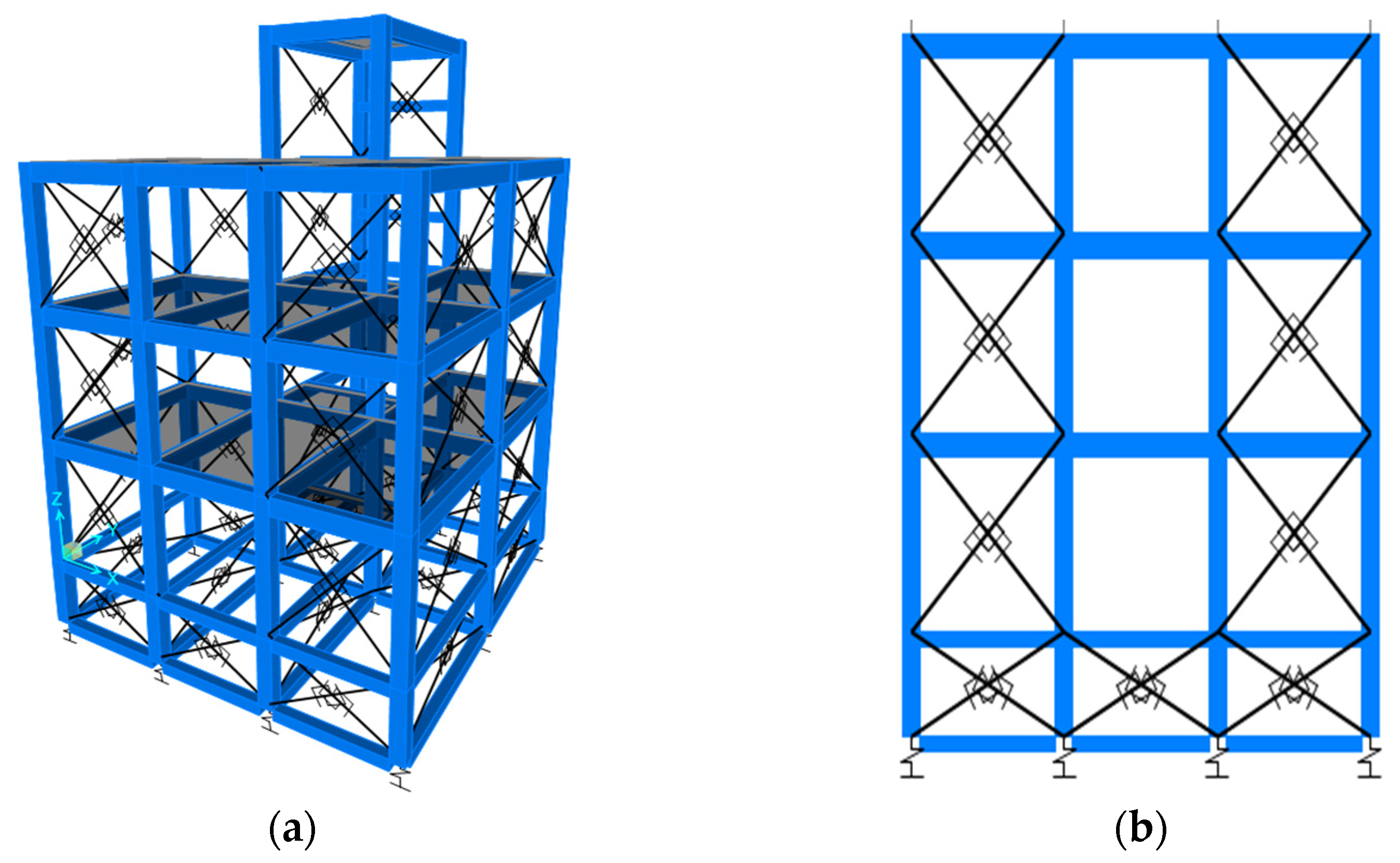
2.4. Finite Element Modeling

The building was numerically modeled using a three-dimensional finite element model in SAP 2000 v.23 [42]. Beams and columns are modeled using 1D (line) element with appropriate sections including reinforcements. The bending stiffness of slab is neglected in the analysis as a common practice, while in plane stiffness of slab is considered using rigid floor diaphragm and loads from slabs are distributed to beams using ‘none’ slab section. The structure is modeled up to foundation top level, which is 1.5 m below the plinth level that includes both plinth beam and foundation tie beams. The effect of solid 230 mm thick brickwork below plinth is modeled with diagonal struts, using a non-linear compression-only link element. A 3D rendered model and an elevation with links used to model diagonal struts and foundation spring are presented in Figure 8. We considered four analysis cases: bare frame model without soil–structure interaction, infill wall model without soil–structure interaction, bare frame model with soil–structure interaction, and infill model with soil–structure interaction. The major features of the four analytical models considered in the analysis are presented in Table 2.
Non-linear hinges were assigned at each end of beam and column elements at a distance of 10% of member length from the joint. The non-linear hinges are defined as per ASCE 41-17 [40]. Nonlinearity of frame is captured only at frame-hinge locations. Further, in infill model, the non-linear compression only links are used modeling inelastic behavior. Springs with six degrees of freedom are placed at each column footing to model SSI.
The capacity curve is obtained by performing pushover analysis in which static non-linear analysis was carried out under displacement controlled incremental acceleration loading, including P-Δ effect. Nonlinear time history analysis is carried out using direct-integration approach, including P-Δ effect to estimate the displacement demands under seven real earthquake ground motions as presented in Table 3. Dynamic analyses were carried out after preloading the structure with deadload plus 30% of the live loads. A summary of modal period for first four modes for the considered analysis scenarios is presented in Table 4. As shown in Table 4, the fundamental vibration period of building increases if soil–structure interaction effect is considered. When infill walls are modeled, the fundamental vibration period is significantly reduced. The yield force, yield displacement, ultimate force, and ultimate displacement for bare frame model were obtained as 750 KN, 40 mm, 2550 KN, and 370 mm, respectively. For infill model, the yield force, yield displacement, ultimate force, and ultimate displacement were estimated as 2000 KN, 35 mm, 2900 KN, and 310 mm, respectively.

2.5. Fragility Analysis

One of the effective tools for seismic vulnerability assessment of structures is the fragility function. Fragility functions can be derived from empirical, analytical, judgmental, and hybrid approaches. Fragility functions fundamentally outline the exceedance probability of particular damage states/performance level under particular value of ground motion intensity measure. Analytical fragility functions can be created from capacity and demand analyses. Seismic demand in terms of spectral displacement was estimated from time history analysis using the seven ground motions listed in Table 3. Capacity estimates are obtained from pushover analysis following the approach suggested by Lagomarsino and Giovinazzi [43]. Table 5 depicts the damage states and capacity functions for the four adopted damage states. In Table 5, dy indicates the yield displacement and du indicates ultimate displacement. The yield displacement and ultimate displacement parameters were estimated using the approach suggested by Elnashai and Di Sarno [44].
Due to limited availability of empirical data and possibility of biases, analytical fragility functions are constructed for various types of structures. Jalayer et al. [45] proposed a method to create analytical fragility functions using unscaled ground motion records. We used the same approach to construct analytical fragility functions. The regression-based fragility model uses the damage to capacity ratio for a particular damage level (DCRLS) for the defined intensity measure (IM). The fragility model proposed by Jalayer et al. [45], which depicts the probability of exceedance of particular DCRLS can be represented by Equation (4) as follows:
P ( D C R L S > 1 | S a ,   χ ) = P ( l n D C R L S > 0 | S a ,   χ ) = 1 ϕ ( l n η D C R L S S a σ l n β D C R L S | S a )   = ϕ ( l n η D C R L S S a σ l n β D C R L S | S a )
where, ϕ ( · ) indicates standard Gaussian cumulative distribution function, χ = [ l n a , b , D C R L S ] is the model parameter and D C R L S S a σ l n D C R L S | S a . Furthermore, σ l n β D C R L S | S a can be estimated as:
E [ l n D C R L S | S a ] = l n η D C R L S S a = l n a + b l n S a
σ l n β D C R L S S a = i = 1 N ( l n D C R L S ,       i ln η D C R L S ,       i | S a ) 2 N 1
where, DCRLS = {DCRLS, i, i = 1: N} is the set of critical demand to capacity ratios for the limit state (LS) obtained from nonlinear time history analysis performed for a suite of N unscaled ground motions, and Sa = {Sa, i, i = 1: N} is the set of respective spectral acceleration values. DCRLS, i and Sa, i are estimated for the ith ground motion record. Similarly, E [ l n D C R L S S a ] is the expected value for the natural logarithm of DCRLS given Sa, η D C R L S S a is the median for DCRLS given Sa, and σ l n β D C R L S S a is the logarithmic standard deviation for DCRLS given Sa.

3. Results and Discussions

For the case study of low-rise RC building located in Kathmandu, Nepal, we performed modal analysis for each analysis scenario, i.e., bare frame without soil–structure interaction, infill model without soil–structure interaction, bare frame with soil–structure interaction, and infill model with soil–structure interaction. The fundamental natural period of bare frame without soil–structure interaction model was obtained as 0.405 s; meanwhile the same for bare frame with soil–structure interaction, infill model without soil–structure interaction, and infill model with soil–structure interaction was respectively 0.445, 0.161, and 0.258 s. Thus, it is found that inclusion of soil–structure interaction slightly increases the vibration period of the structure. Due to additional stiffness provided by the infill walls, the vibration period of the models with infill walls is much lower than those without infill walls. The infill model with soil–structure interaction is the most realistic representation of the actual structure. Fragility functions for four damages states considering the four building models were constructed. Figure 9 shows the fragility functions for bare frame model without considering the effects of soil–structure interaction. As shown in Figure 9, the exceedance probabilities of slight, moderate, extensive, and collapse damage states at 1 g spectral acceleration are respectively 100, 95, 50, and 20%.
Figure 10 depicts the fragility functions for low-rise RC buildings for infill frame model without considering soil–structure interaction. As shown in Figure 10, the exceedance probabilities for slight, moderate, extensive, and collapse damage states at 1 g, spectral accelerations are 88, 78, 55, and 45%, respectively. This highlights that the infill walls have a greater role in more severe damage states (extensive and collapse).
Fragility functions for low-rise RC building for bare frame model considering soil–structure interaction are presented in Figure 11. As shown in Figure 11, exceedance probabilities for slight, moderate, extensive, and collapse damage states at 1 g, spectral acceleration are 100, 97, 55, and 25%, respectively. It is observed that the effect of soil–structure interaction is not significantly large for low-rise RC buildings. The higher damage states are almost unaffected.
The most realistic scenario for soft soil deposits is reflected by infill model including the effects of soil–structure interaction. Fragility functions for low-rise RC building for infill model considering soil–structure interaction are presented in Figure 12. Together with the analytical fragility functions, existing empirical fragility functions [46] for low-rise substandard RC building class are also plotted in Figure 12 for comparison. The empirical fragility functions were derived using the damage data collected after major earthquakes in Nepal. The authors used a ground motion prediction equation-based intensity measure to create fragility functions. Furthermore, the damage statistics were reinterpreted to create a homogenized damage state, thus the authors considered three broad damage states. As shown in Figure 12, the exceedance probabilities for slight, moderate, extensive, and collapse damage states at 1 g are 92, 80, 48, and 31%, respectively. Figure 12 highlights that the analytical fragilities are much higher than the empirical ones. Also, it should be noted that the exceedance probabilities are quite high even at low spectral acceleration values for the analytical models. Although empirical models are significantly more representative, as such models do not suffer modeling uncertainties, empirical models are also likely to get affected by the uncertainties arising from intensity measure value allocation and exacting definition of damage state for individual building. To this end, both empirical and analytical models are to be carefully judged before using. The results nevertheless highlight the effect of SSI and brick infill walls in overall seismic fragility of the building types studied here.

4. Conclusions

Realistic dissemination of seismic vulnerability is pivotal not only for pre-earthquake strengthening initiatives, but also for post-earthquake loss assessment, recovery planning, etc. A large proportion of residential buildings in the Kathmandu Valley are low-rise residential buildings resting on soft soils. In order to understand the effects of modelling uncertainties in seismic performance assessment of such structures, different models with/without infill walls, and SSI effects of representative buildings are studied by numerical simulation using the finite element method. Analytical fragility functions of the models are created using non-linear time history analysis using a set of real earthquake ground motions. Using the demand to capacity ratio approach, we derived fragility functions for four damage states: slight, moderate, extensive, collapse for four analysis scenarios: bare frame model without considering soil–structure interaction, infill model without considering soil–structure interaction, bare frame model considering soil–structure interaction, and infill model considering soil–structure interaction. As expected, the fundamental vibration period is significantly reduced when infills are modeled; however, soil–structure interaction slightly increases the fundamental vibration period. Fragility functions developed for the four cases highlight that soil–structure interaction has more effects on the lower damage states, while infills particularly affect the higher damage states increasing their exceedance probabilities at designated spectral acceleration values. Comparison with the existing empirical fragility models suggests that the analytical fragilities are significantly higher than those inferred from empirical loss data. The results highlight the importance of modelling infill walls and SSI effects. The large difference in empirical and analytical fragility functions warrant for future research. These differences could arise from a number of different factors including definitions of damage states, modelling uncertainties, etc. Another important aspect that is not considered in this study is the damping provided by the soil and its potential inelastic deformation. These factors along with many other uncertainties mentioned above leave room for extensive future research to better understand and model seismic fragility of low-rise residential buildings in the Kathmandu Valley.

Author Contributions

Conceptualization, D.G. and R.A.; Methodology, R.A., D.G. and R.R.; Software, R.A., D.G. and P.G.; Validation, R.R., D.G. and R.A.; Formal analysis, R.A. and D.G; Investigation, R.A., P.G., R.B., R.S. and R.G.; Resources, R.B., R.S. and R.G.; Data curation, R.A., D.G. and R.R.; Writing—original draft preparation, R.A., D.G. and R.R.; Writing—review and editing, R.A., D.G., R.R., P.G., R.B., R.S. and R.G; Visualization, R.A. and D.G.; Supervision, R.R.; Project administration, R.A.; Funding acquisition, R.A. All authors have read and agreed to the published version of the manuscript.

Funding

This research received no external funding.

Data Availability Statement

Data used in this paper can be obtained from the corresponding author upon reasonable request.

Conflicts of Interest

The authors declare no conflict of interest.

References

  1. Gautam, D.; Rodrigues, H.; Bhetwal, K.K.; Neupane, P.; Sanada, Y. Common structural and construction deficiencies of Nepalese buildings. Innov. Infrastruct. Solut. 2016, 1, 1. [Google Scholar] [CrossRef] [Green Version]
  2. Gautam, D.; Chaulagain, H. Structural performance and associated lessons to be learned from world earthquakes in Nepal after 25 April 2015 (MW 7.8) Gorkha earthquake. Eng. Fail. Anal. 2016, 68, 222–243. [Google Scholar] [CrossRef]
  3. Sezen, H.; Whittaker, A.; Elwood, K.; Mosalam, K. Performance of reinforced concrete buildings during the August 17, 1999 Kocaeli, Turkey earthquake, and seismic design and construction practise in Turkey. Eng. Struct. 2003, 25, 103–114. [Google Scholar] [CrossRef]
  4. Romão, X.; Costa, A.; Paupério, E.; Rodrigues, H.; Vicente, R.; Varum, H. Field observations and interpretation of the structural performance of constructions after the 11 May 2011 Lorca earthquake. Eng. Fail. Anal. 2013, 34, 670–692. [Google Scholar] [CrossRef]
  5. Verderame, G.M.; Ricci, P.; De Luca, F.; Del Gaudio, C.; de Risi, M.T. Damage scenarios for RC buildings during the 2012 Emilia (Italy) earthquake. Soil Dyn. Earthq. Eng. 2014, 66, 385–400. [Google Scholar] [CrossRef] [Green Version]
  6. Del Gaudio, C.; De Risi, M.T.; Ricci, P.; Verderame, G.M. Empirical drift-fragility functions and loss estimation for infills in reinforced concrete frames under seismic loading. Bull. Earthq. Eng. 2019, 17, 1285–1330. [Google Scholar] [CrossRef]
  7. Malla, S.; Karanjit, S.; Dangol, P.; Gautam, D. Seismic performance of high-rise condominium building during the 2015 Gorkha earthquake sequence. Buildings 2019, 9, 36. [Google Scholar] [CrossRef] [Green Version]
  8. Barbosa, A.; Fahnestock, L.A.; Fick, D.R.; Gautam, D.; Soti, R.; Wood, R.; Moaveni, B.; Stavridis, A.; Olsen, M.; Rodrigues, H. Performance of Medium-to-High Rise Reinforced Concrete Frame Buildings with Masonry Infill in the 2015 Gorkha, Nepal, Earthquake. Earthq. Spectra 2017, 33, 197–218. [Google Scholar] [CrossRef]
  9. Gautam, D.; Forte, G.; Rodrigues, H. Site effects and associated structural damage analysis in Kathmandu Valley, Nepal. Earthq. Struct. 2016, 10, 1013–1032. [Google Scholar] [CrossRef]
  10. Varum, H.; Furtado, A.; Rodrigues, H.; Dias-Oliveira, J.; Vila-Pouca, N.; Arede, A. Seismic performance of the infill masonry walls and ambient vibration tests after the Ghorka 2015, Nepal earthquake. Bull. Earthq. Eng. 2016, 15, 1185–1212. [Google Scholar] [CrossRef]
  11. Perrone, D.; Leone, M.; Aiello, M.A. Non-linear behaviour of masonry infilled RC frames: Influence of masonry mechanical properties. Eng. Struct. 2017, 150, 875–891. [Google Scholar] [CrossRef]
  12. Blasi, G.; Perrone, D.; Aiello, M.A. Fragility functions and floor spectra of RC masonry infilled frames: Influence of mechanical properties of masonry infills. Bull. Earthq. Eng. 2018, 16, 6105–6130. [Google Scholar] [CrossRef]
  13. Gallipoli, M.R.; Mucciarelli, M.; Vona, M. Empirical estimate of fundamental frequencies and damping for Italian buildings. Earthq. Eng. Struct. Dyn. 2009, 38, 973–988. [Google Scholar] [CrossRef]
  14. Ricci, P.; Verderame, G.M.; Manfredi, G. Analytical investigation of elastic period of infilled RC MRF buildings. Eng. Struct. 2010, 33, 308–319. [Google Scholar] [CrossRef]
  15. Furtado, A.; Vila-Pouca, N.; Varum, H.; Arêde, A. Study of the seismic response on the infill masonry walls of a 15-storey reinforced concrete structure in Nepal. Buildings 2019, 9, 39. [Google Scholar] [CrossRef] [Green Version]
  16. Di Domenico, M.; De Risi, M.T.; Ricci, P.; Verderame, G.M.; Manfredi, G. Empirical prediction of the in-plane/out-of-plane interaction effects in clay brick unreinforced masonry infill walls. Eng. Struct. 2021, 227, 111438. [Google Scholar] [CrossRef]
  17. Mazza, F.; Donnici, A. In-plane and out-of-plane seismic damage of masonry infills in existing r.c. structures: The case study of De Gasperi-Battaglia school in Norcia. Bull. Earthq. Eng. 2021, 19, 345–376. [Google Scholar] [CrossRef]
  18. Furtado, A.; Rodrigues, H.; Arede, A.; Varum, H. Mechanical properties characterization of different types of masonry infill walls. Front. Struct. Civ. Eng. 2020, 14, 411–434. [Google Scholar] [CrossRef]
  19. De Risi, M.T.; Furtado, A.; Rodrigues, H.; Melo, J.; Verderame, G.M.; António, A.; Varum, H.; Manfredi, G. Experimental analysis of strengthening solutions for the out-of-plane collapse of masonry infills in RC structures through textile reinforced mortars. Eng. Struct. 2020, 207, 110203. [Google Scholar] [CrossRef]
  20. Verderame, G.M.; Ricci, P.; De Risi, M.T.; Del Gaudio, C. Experimental Assessment and Numerical Modelling of Conforming and Non-Conforming RC Frames with and without Infills. J. Earthq. Eng. 2019, 1–42. [Google Scholar] [CrossRef]
  21. Pujol, S.; Fick, D. The test of a full-scale three-story RC structure with masonry infill walls. Eng. Struct. 2010, 32, 3112–3121. [Google Scholar] [CrossRef]
  22. Ricci, P.; De Luca, F.; Verderame, G.M. 6th April 2009 L’Aquila earthquake, Italy: Reinforced concrete building performance. Bull. Earthq. Eng. 2011, 9, 285–305. [Google Scholar] [CrossRef] [Green Version]
  23. Gautam, D.; Adhikari, R.; Rupakhety, R. Seismic fragility of structural and non-structural elements of Nepali RC buildings. Eng. Struct. 2021, 232, 111879. [Google Scholar] [CrossRef]
  24. Pokhrel, A.; Gautam, D.; Chaulagain, H. Effect of variation on infill masonry walls in the seismic performance of soft story RC building. Aust. J. Struct. Eng. 2018, 20, 1–9. [Google Scholar] [CrossRef]
  25. Stewart, J.P.; Fenves, G.L.; Seed, R.B. Seismic Soil-Structure Interaction in Buildings. I: Analytical Methods. J. Geotech. Geoenvironmental Eng. 1999, 125, 26–37. [Google Scholar] [CrossRef]
  26. Hosseinzadeh, N.; Davoodi, M.; Roknabadi, E.R. Shake Table Study of Soil Structure Interaction Effects in Surface and Embedded Foundations. In Proceedings of the 15th World Conference in Earthquake Engineering, Lisbon, Portugal, 24–28 September 2012; pp. 24–28. [Google Scholar]
  27. Mylonakis, G.; Gazetas, G. Seismic soil-structure interaction: Beneficial or detrimental? J. Earthq. Eng. 2000, 4, 277–301. [Google Scholar] [CrossRef]
  28. Kraus, I.; Džakić, D. Soil-Structure Interaction Effects on Seismic Behavior of Reinforced Concrete Frames. In Proceedings of the SE-50EEE International Conference on Earthquake Engineering, Skopje, Macedonia, 29–31 May 2013. [Google Scholar]
  29. Karatzetzou, A.; Pitilakis, D.; Abbas, N.; Cattari, S. Effects of soil-structure interaction on performance based assessment of masonry buildings. In Proceedings of the 15th World Conference in Earthquake Engineering, Lisbon, Portugal, 24–28 September 2012; pp. 24–28. [Google Scholar]
  30. Jie, G.; Preisig, M.; Jeremić, B. Benefits and Detriments of Soil Foundation Structure Interaction. In Proceedings of the Geo-Denver, ASCE, Denver, CO, USA, 18–21 February 2007. [Google Scholar] [CrossRef]
  31. Eurocode 8, Design of Structures for Earthquake Resistance, Part 1: General Rules, Seismic Actions and Rules for Buildings. Belgium, 2004. Available online: http://www.confinedmasonry.org/wp-content/uploads/2009/09/Eurocode-8-1-Earthquakes-general.pdf (accessed on 1 January 2022).
  32. ASCE/SEI 7-10, Minimum Design Loads for Buildings and Other Structures. United States, 2010. Available online: https://ascelibrary.org/doi/book/10.1061/9780784412916 (accessed on 1 January 2022).
  33. Bureau of Indian Standards, IS 1893 (Part1):2016 Indian Standard Criteria for Earthquake Resistant Design of Structures. India, 2016. Available online: https://nitsri.ac.in/Department/Civil%20Engineering/CSE_202_Chapter_4-1893-part-1-2016-1pdf.pdf (accessed on 1 January 2022).
  34. Department of Urban Development and Building Construction, NBC-105:2020 Nepal National Building Code for Seismic Design of Buildings in Nepal. Nepal, 2020. Available online: https://www.lsmcebps.gov.np/UploadFiles/NBC105_2020.pdf (accessed on 1 January 2022).
  35. Adhikari, A.; Rao, K.R.M.; Gautam, D.; Chaulagain, H. Seismic vulnerability and retrofitting scheme for low-to-medium rise reinforced concrete buildings in Nepal. J. Build. Eng. 2019, 21, 186–199. [Google Scholar] [CrossRef]
  36. Gautam, D. Unearthed lessons of 25 April 2015 Gorkha earthquake (MW 7.8): Geotechnical earthquake engineering perspectives. Geomat. Nat. Hazards Risk 2017, 8, 1358–1382. [Google Scholar] [CrossRef] [Green Version]
  37. Gazetas, G. Formulas and charts for impedances of surface and embedded foundations. J. Geotech. Eng. 1991, 117, 1363–1381. [Google Scholar] [CrossRef]
  38. Asteris, P. Lateral Stiffness of Brick Masonry Infilled Plane Frames. J. Struct. Eng. 2003, 129, 1071–1079. [Google Scholar] [CrossRef] [Green Version]
  39. Al-Chaar, G.; Issa, M.; Sweeney, S. Behavior of Masonry-Infilled Nonductile Reinforced Concrete Frames. J. Struct. Eng. 2002, 128, 1055–1063. [Google Scholar] [CrossRef]
  40. Applied Technolgy Council. Evaluation of Earthquake Damaged Concrete and Masonry Wall Buildings; ATC: Redwood City, CA, USA, 1998. [Google Scholar]
  41. Panagiotakos, T.B.; Fardis, M.N. Seismic response of infilled RC frame structures. In Proceedings of the 11th World Conference on Earthquake Engineering, Acapulco, Mexico, 23–28 June 1996. [Google Scholar]
  42. ETABS, version 18.1.1, Computers and Structures Inc.: Walnut Creek, CA, USA, 2020.
  43. Lagomarsino, S.; Giovinazzi, S. Macroseismic and mechanical models for the vulnerability and damage assessment of current buildings. Bull. Earthq. Eng. 2006, 4, 415–443. [Google Scholar] [CrossRef]
  44. Elnashai, A.S.; di Sarno, L. Fundamentals of Earthquake Engineering; Wiley: New York, NY, USA, 2008. [Google Scholar] [CrossRef]
  45. Jalayer, F.; Ebrahimian, H.; Miano, A.; Manfredi, G.; Sezen, H. Analytical fragility assessment using unscaled ground motion records. Earthq. Eng. Struct. Dyn. 2017, 46, 2639–2663. [Google Scholar] [CrossRef]
  46. Gautam, D.; Fabbrocino, G.; de Magistris, F.S. Derive empirical fragility functions for Nepali residential buildings. Eng. Struct. 2018, 171, 617–628. [Google Scholar] [CrossRef]
Figure 1. Typical floor plan of the case study building.
Buildings 12 00072 g001
Figure 2. Geometrical and reinforcement details of RC beam section.
Buildings 12 00072 g002
Figure 3. Geometrical and reinforcement details of column section.
Buildings 12 00072 g003
Figure 4. Typical arrangement of isolated footing.
Buildings 12 00072 g004
Figure 5. Equivalent soil spring model with six degrees of freedom [37].
Buildings 12 00072 g005
Figure 6. Equivalent strut model for masonry infills.
Buildings 12 00072 g006
Figure 7. Force–displacement relation proposed by Panagiotakos and Fardis for the equivalent diagonal strut [41].
Buildings 12 00072 g007
Figure 8. (a) 3D model for infill considering soil–structure interaction scenario, (b) 2D elevation of infill considering soil–structure interaction along Grid-1.
Buildings 12 00072 g008
Figure 9. Fragility functions for low-rise RC building for bare frame without considering soil–structure interaction.
Buildings 12 00072 g009
Figure 10. Fragility functions for low-rise RC building for infill frame model without considering soil–structure interaction.
Buildings 12 00072 g010
Figure 11. Fragility functions for low-rise RC building for bare frame model considering soil–structure interaction.
Buildings 12 00072 g011
Figure 12. Fragility functions for low-rise RC building for infill model considering soil–structure interaction.
Buildings 12 00072 g012
Table 1. Geometric and material properties used for finite element modeling.
ComponentDescriptionDetails
FrameTypeSpecial moment resisting frame (SMRF)
No. of stories3
No. of bays in X-direction3
No. of bays in Y-direction2
Story height2.87 m
Total width along X-axis8.54 m
Total width along Y-axis9.14 m
Size of beam230 × 355 mm
Size of column305 × 305 mm
Thickness of slab125 mm
LoadLive load at floor slab2.5 KN/m2
Live load at roof1.5 KN/m2
Staircase load3 KN/m2
External wall load8.98 to 12.83 KN/m
Internal wall load4.86 to 6.94 KN/m
Isolated square footing1.52 × 1.52 m, 1.5 m below the plinth level
MaterialGrade of concrete20 MPa for all concrete members
Grade of steel rebarFe-500 for all RCC members
Brickwork7.5 MPa bricks in 1:6 cement-sand mortar for 230 mm thick walls
Table 2. Features of finite element models.
ModelFeatures
Bare frame model without soil–structure interaction
  • Stiffness due to infill wall in superstructure not being modeled.
  • Structure is fixed at foundation top-level.
Infill model without soil–structure interaction
  • Stiffness due to infill wall in superstructure is modeled as diagonal strut with 2-joint non-linear link-element.
  • Structure is fixed at foundation top-level.
Bare frame model considering soil–structure interaction
  • Stiffness due to infill wall in superstructure is not modeled.
  • Structure is supported at foundation top-level on grounded spring with appropriate stiffness in six degrees of freedom
Infill model with soil–structure interaction
  • Stiffness due to infill wall in superstructure is modeled as diagonal strut with 2-joint non-linear link-element.
  • Structure is supported at foundation top-level on grounded spring with appropriate stiffness in six degrees of freedom
Table 3. Acceleration time histories used for analysis.
EarthquakePGA (g)StationMagnitude (Mw)
Gorkha (2015)0.1771Kathmandu7.8
Imperial Valley-06 (1979)0.2354EC County Center FF6.53
Kocaeli Turkey (1999)0.3642Duzce7.51
Northridge-01 (1994)0.4434Beverly Hills-14145 Muhol6.69
Loma Prieta (1989)0.5699LGPC6.93
Kobe Japan (1995)0.6711Takatori6.9
Chi-Chi Taiwan (1999)0.7604CHY0287.62
Table 4. Modal periods for various modeling scenarios.
Mode No.Modal Period (Sec)
Bare Frame (fixed)Bare Frame (SSI)Infill (Fixed)Infill (SSI)
Mode 10.4050.4450.1610.258
Mode 20.3970.4310.1290.200
Mode 30.3420.3630.0950.116
Mode 40.1560.1580.0750.096
Table 5. Capacity functions of various damage states for fragility analysis [43].
Capacity FunctionDamage States
D1 = 0.7 dySlight damage
D2 = 1.5 dyModerate damage
D3 = 0.5(dy + du)Extensive damage
D4 = duComplete damage
Publisher’s Note: MDPI stays neutral with regard to jurisdictional claims in published maps and institutional affiliations.

