1. Introduction
Industrialised house building (IHB) companies currently face challenges in balancing the degree of standardisation and customisation in their offerings [
1,
2]. This is particularly true for house building companies that design and manufacture highly customised building components [
3]. Typically, they design and develop solutions by involving the customers resulting in unique buildings. Thus, they are continuously faced with fluctuating requirements and small changes, such as added or removed building components or the placement of new components resulting in significant variation in both structural and technical perspectives.
In addition, they often find it difficult to provide distinctive products to meet varying customer needs and at the same time to fulfil legal regulations, market demands, and production constraints [
4]. This may result in the high involvement of designers to validate and adjust individualised solutions. Today, ETO-based components are characterised by a growing degree of customised and unique nature where a design starts from scratch, and the level of variation creates a bottleneck in the design process commonly resulting in a high lead time and incurred costs [
2,
5].
Here, designers are entitled to identify the most adequate solutions to fulfil specific design requirements [
6]. To satisfy customer demands, companies can use different production strategies [
7] based on the point at which the customer enters the supply chain, which is referred to as the customer order decoupling point (CODP). According to Hansen [
8], four strategies used by companies are engineer-to-order (ETO), modify-to-order (MTO), configure-to-order (CTO) and select variant. House building has been considered as the biggest ETO sector where a project is engineered and produced after an order has been received [
9].
IHB companies can use different engineering and production strategies [
10]. Many companies have developed building systems based on different strategies to meet market needs [
11]. However, to gain competitive advantages in the market, companies adopt ETO-based operation strategies and offer more customisation choices to attract customers. Thus, to manage customisation, the demands for new methods and tools to support the design and allow the designers to be flexible at the development stage for rapid creation are greatly amplified [
12].
Looking at the cost-effective methods and tools established in other industries, such as manufacturing and software, we can realize how companies successfully address the challenges of customisation. Product platform strategies and standardisation efforts have had a significant impact on the development time and cost reduction [
13]. Product platforms are well-acknowledged as a means to efficiently manage ETO-based products [
14]. In the IHB industry, flexibility in design and customisation can be achieved with the support of platform-based product development and can be managed through industrialised building systems [
2,
11].
However, a broad definition of a product platform cannot be applied directly to ETO-based building components in IHB. Due to the high level of customisation, IHB companies are forced to develop unique solutions for each new building to satisfy the specific requirements, which are often beyond the defined boundary [
3]. Every project is unique, and the reuse of assets is limited. In this scenario, utilising a traditional component or modular-based platform by taking advantage of clearly predefined components does not suffice [
15].
One way to support the design process of ETO building components is to use a coherent platform model [
16] that focuses on the reuse of engineering assets, which is more of the skills and knowledge to accomplish higher efficiency during development [
11]. The design platform approach (DPA) proposed by Andre et al. [
17] has been acknowledged as such an approach that facilitates the structuring and reuse of a company′s engineering assets in circumstances where customer needs are unique and tend to change over time. For ETO companies to be successful in the process of developing customised products, design reuse has been considered an enabler [
16].
The DPA was originally developed based on the findings from four cases, where two cases are from system suppliers in the automotive industry, one customised production system supplier and one system supplier in the aircraft industry [
17]. The DPA has also been applied in IHB for business premises and single-family houses using volumetric and element building systems [
3,
5]. The first study proposes a product lifecycle management (PLM) system solution by applying DPA to manage the assets and support the customisation ability for IHB companies [
3].
Another study was performed to expand the application of DPA and demonstrate how to formalise the knowledge with an information modelling method in the design process of single-family IHB [
5]. In this study, DPA was applied to a system supplier of post and beam building systems. Thus, the applicability of DPA was further explored to show how it can be used in IHB by a new different case focusing on a system supplier and resulting in significant benefits for ETO-based components.
In general, the ability to handle the complexities occurring due to geometry is enabled by knowledge-based engineering (KBE) systems and product configurators [
18]. The study conducted by Jensen et al. [
1] showed that computer-aided design (CAD) tools used in the manufacturing industry can offer new opportunities for the design automation of building components in the IHB [
12]. Parametric modelling is a promising technique to automate workflows based on building information modelling (BIM) in the design process, which enables a rapid generation of designs alternatives by embedding domain expertise in models [
19].
The information and communications technology (ICT) support system should have parametric choices and preferably object-oriented capabilities [
20] and the use of fully parametric 3D CAD modelling in buildings offers numerous benefits [
21,
22]. To successfully design and develop ETO-based products, efficient tools and methods for integrated and automated design are needed throughout the development process [
23]. Thus, the purpose of this research is to test and evaluate how the reuse of design assets can be achieved by using a parametric modelling approach to support the design process of ETO-based components in a post and beam building system.
This paper introduces research aimed at improving the design phase of IHB through a pilot-case study as part of the platform development. The reuse of design assets was investigated in the modelling process of an ETO component to facilitate design automation. Moreover, the study builds upon the work of Andre et al. [
17], and this research further expands the body of knowledge on the DPA by introducing a method using parametric modelling.
In this context, a closer analysis of the building system shows that the building components have mixed production strategies when compared with the strategies defined by Hansen [
8]. Some components of the building system can be standardised and have an MTO approach, some parts come under the CTO approach, whereas the remainder of the components has the ETO nature that should be engineered and customised according to customer requirements. A steel bracket was selected as the experimental object for this study as it has an ETO nature in its design.
3. Research Methodology
The design research methodology (DRM), proposed by Blessing and Chakrabarti [
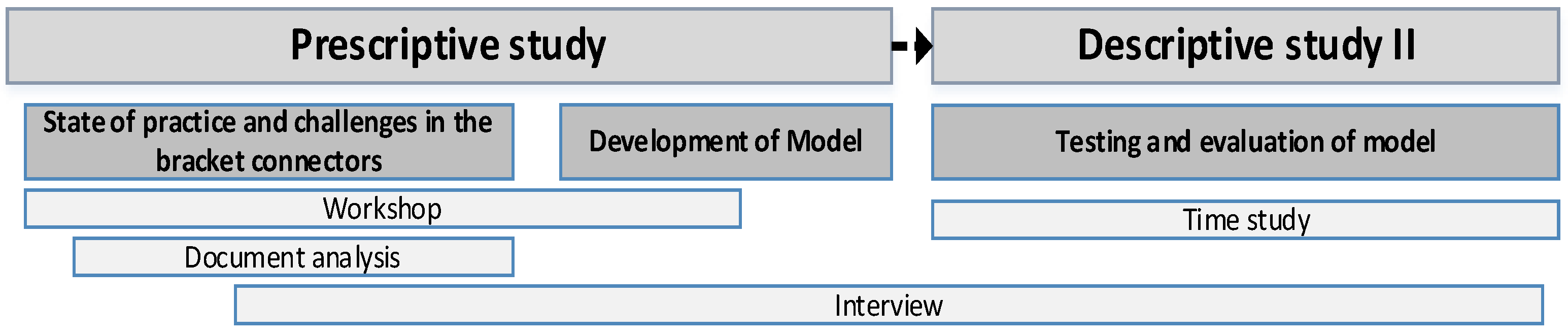
39] was adopted as the overall framework for this research project. DRM is a four-stage iterative process consisting of four stages, named research clarification (RC), descriptive study I (DS I), prescriptive study (PS), and finally descriptive study II (DS II). RC is the initial stage, which concerns the identification of a research gap to formulate the goal with the support of literature studies. DS I focuses on gaining deeper knowledge and describing the ‘as-is’ situations by conducting empirical data collection and analysis.
PS is concerned with the systematic development of new support for the improvement of an existing problem to demonstrate the ‘to-be condition. DS II focuses on evaluation for all the criteria considered to develop the support method in the PS stage. The DRM framework is developed to support research within engineering design by developing innovative solutions to practical problems, which makes it suitable for this study. This study is positioned in the PS and DS II, where a method was synthesized and developed in the PS stage to support the design phase followed by an evaluation of the developed method as part of the DS II stage. The workflow process adopted for this study is illustrated in
Figure 1.
A qualitative study was conducted with a combination of a literature review and a case study at one of the Swedish multi-storey house builders using the glulam post and beam system. An inductive approach was employed for this study where a support method was developed based on the findings from a detailed study of a building component [
40].
The study reported an ongoing platform development at the case company. The unit of analysis was the design process of bracket connectors as the study targeted to gain a holistic understanding of challenges and solutions to improve the current state. The findings from the detailed study including testing and evaluation supported formalising the method. The empirical data were collected through a workshop, semi-structured interviews, and document analysis.
A workshop was conducted initially to brainstorm the needs and current challenges and to understand the company’s vision by including four design engineers and two from management. The main agenda for this workshop was to improve the current design process of steel connectors.
In this session, the current state and challenges involved in the bracket design process were discussed and finally, solutions to structure and improve the process were brainstormed and formalised. As an outcome of the workshop, a project team was formed aiming at different improvement activities as part of platform development. The project team consisted of three engineers—a senior CAD designer, structural engineer, research & development manager—and the researcher.
Workshop: A workshop was conducted initially to brainstorm the needs, current challenges and understand the company’s vision by including six participants. Four from the design team; two structural engineers, the design engineer and senior CAD designer, and two from the management—the managing director and design manager. The selection of participants was based on their experience and knowledge in the overall building design. The main agenda for this workshop was to improve the current design process of steel connectors in the BS.
In this session, the current state and challenges involved in the bracket design process were discussed, and finally the solutions to structure and improve the process were brainstormed and formalised. As an outcome of the workshop, a project team was formed aiming at different improvement activities as a part of the platform development. The project team consisted of three engineers—a senior CAD designer, two structural engineers where one was also the research & development manager—and the researcher.
Interviews: Four semi-structured interviews were conducted with key persons from the design department: the design manager, senior structural engineer, senior CAD designer, and structural engineer. These participants closely work together in Trä 8 building projects and are knowledgeable in handling ETO-based requirements from the customer. To generate qualitative data, the interview guide was designed by including open-ended questions on the bracket design for the respondents to provide in-depth facts on the process [
40].
The potential design elements and assets in the conceptual, system-level and detailed design phase of bracket connectors were extracted, which are tangible and intangible knowledge. Additionally, unstructured interviews were frequently organized with the senior CAD designer to understand the current knowledge, challenges, and opportunities during the design of connectors. These interviews provided an opportunity to dig deeper into questions that emerged during the workshop. The current state of the bracket design process and assets were mapped based on the data collected during the interviews and workshop.
Document analysis: The analysis of documents from previously finished projects was initiated in parallel with the interviews to obtain in-depth knowledge about the brackets used in those projects. The documents related to the design of the connectors from the projects were reviewed, including the structural calculations, 3D models of buildings, design templates, excel spreadsheets, 2D component drawings, bill of materials, activity plans for different projects, component library, etc. [
41].
Documents can provide background information and broad coverage of data and are, therefore, helpful in contextualizing a subject by refining ideas, identifying conceptual boundaries, and pinpointing the fit and relevance (ibid). The details of parameters used for load calculations—the different bracket variants used in the previous projects along with their detailed drawing—were extracted from this analysis.
The analysis followed these steps, (1) gather documents, such as the BOM list and drawings linked to selected projects; (2) extract the detailed drawings of brackets based on the beamwidth for each project from the component library; (3) classify variants according to reuse in these projects; (4) verify these with the BOM list and BIM model; and (5) map variants to the frame of standard beamwidth. Thus, the analysis supported initiating a standard frame for the proposed approach.
As a foundation for data analysis, the interviews were audio-recorded and later transcribed into text. The transcribed materials were examined and analysed individually and coded using the procedures recommended by Miles et al. [
42]. From a qualitative research perspective, the method triangulation supports the internal validity of this study by adopting multiple data collection methods as the empirical data were gathered from workshops, interviews and document analysis. Triangulation is often utilized to check the consistency of findings [
43].
The project team meetings that were conducted frequently helped to lay the foundation for the development of a computer-based support method for bracket modelling with the support of DPA. The empirical data collected were analysed with the theoretical construct to synthesis and develop the method. First, the standard parameters and dimensions for the bracket connection were formulated as part of asset identification [
17]. Then, the design knowledge and rules were captured in Visual Basic application (VBA) software and were integrated with the CAD tool. In other words, the algorithm was developed using VBA connected to the BIM tool (Tekla Structures) through the application programming interface (API) in Tekla Structures.
Finally, during the DS II stage of DRM, an evaluation was conducted to investigate the impact of the support method and its ability to realise the desired situation [
39]. For this, a time study was conducted to review the design lead time, cost, and quality-related aspects for both the manual and parametric approaches of modelling the brackets. Moreover, evaluation was also conducted with design engineers as the focus were to support the design process. It was performed by using the findings on critical success factors on the design phase of IHB from Thajudeen et al. [
44] to evaluate the impact of this approach on selected success factors.
4. Case Study
This section details how the detailed study was conducted at the case company. A bracket connector was chosen to test how the design assets related to the components were identified and formalised to develop the design solution space by using a parametric modelling approach.
4.1. Case Company Description
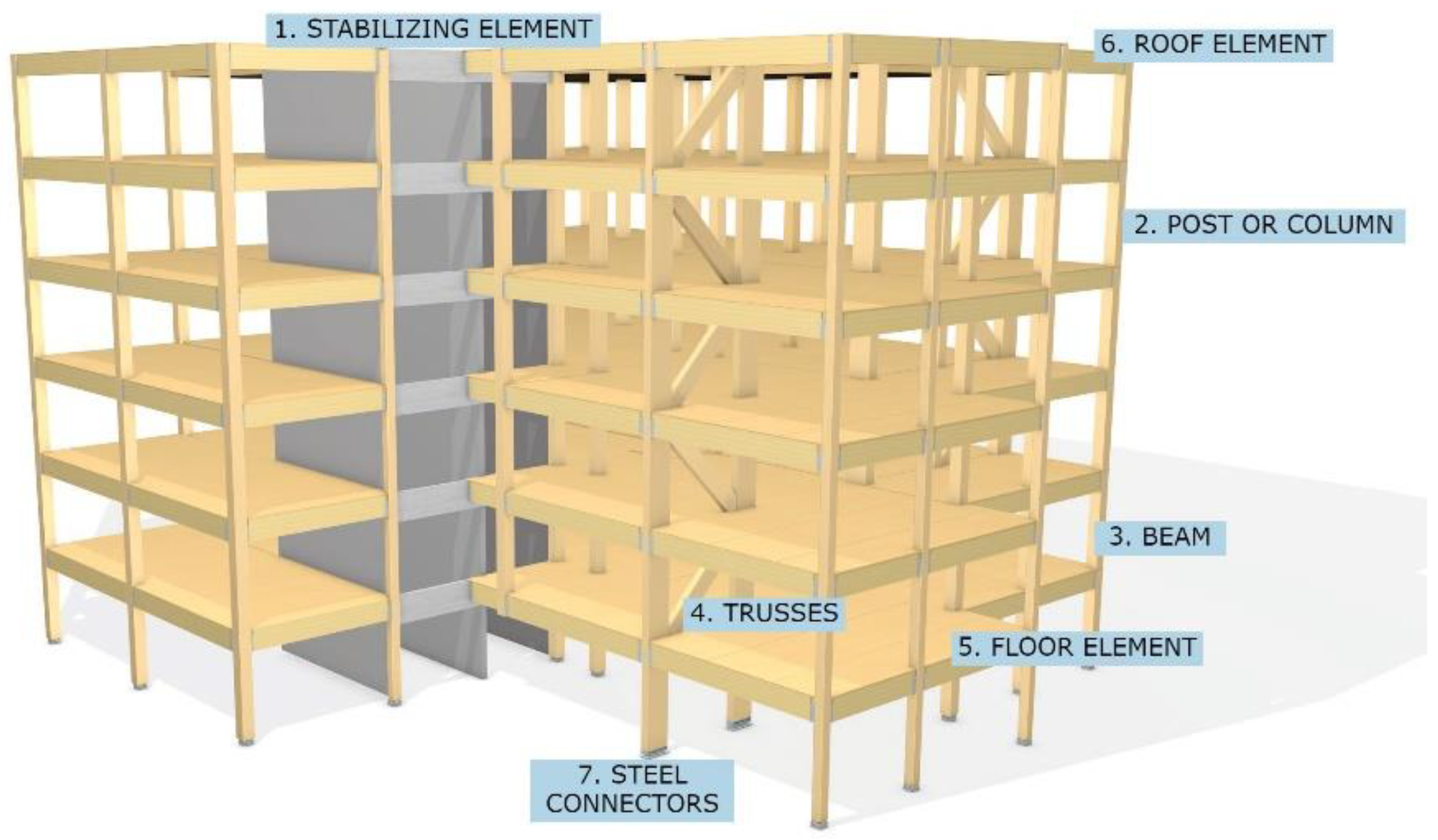
The case company is one of the leading manufacturers of glulam (glued laminated wood) in Europe with a turnover of €27 M and an annual production capacity of 55,000 m³. In 2007, the company launched a unique post and beam building system in the multi-storey house building market named the Trä 8 building system. The system was developed based on the prefabricated technique, and the materials used are glulam and laminated veneer lumber (LVL).
As implied by the name, the system can be used for up to 8-m of a free span that enables flexibility for architectural designs. The main components of the building system include pillar/post, beams, trusses for stabilization made of glued wood, floor elements, roof elements made of Kerto material, and steel connectors. The components of the Trä 8 building system are presented in
Figure 2.
4.2. The Detailed Study on Bracket Connectors Used in the Building System
The brackets are engineered building components used to transfer load from one component to another. The vertical structural post and horizontal beams are connected to form a structural frame where steel connections play a critical role in the structural stability when subjected to lateral loadings.
From a structural perspective, the post and beam are the main load-bearing structures, and the loads from the floor element are transferred through different connectors to this structure. Thus, the main purpose is to have the loads transferred from the floors to the vertical columns. At the same time, they function as a stabilising element for the building in transferring both vertical and horizontal loads to the wooden trusses. The height and width of the connectors depend on the dimensions of the beam and the load transmitting from one component to another.
In a post and beam building system, brackets are extensively used components to connect the column and beam. The number of bracket connectors used in the projects is high when compared to other types of connectors used in the BS. Thus, approximately 60% of the design time is dedicated to designing the connectors as it is challenging to reuse the variants within or across projects. This results in a high number of variants after the completion of each project.
The variants are generated based on several parameters of interconnecting parts, for instance, variations in the number of screws in primary and secondary objects, the width, the height, and the span of the beam. Thus, none of the connectors can be reused completely and exactly the same; however, to some extent, the concept of designing the connector can be reused. The main challenges with the bracket connectors identified include a high number of variants due to the fluctuation requirements, a longer design lead time, less standard solutions, and poor documentation of knowledge.
Due to these reasons, brackets have been considered as the most critical component of the building system as they have an ETO nature. This can be also justified as the reason for the selection of the case company. Thus, any improvement steps taken for the bracket component to optimise the design process makes a significant impact in term of design productivity. Here, support is essential for the designers to improve the existing design process and execute the modelling of brackets quicker. Therefore, a method utilising reuse of design knowledge and automation of processes are necessary to effectively manage bracket variants having geometric complexity. The following steps describe the detailed study in the bracket design.
4.2.1. Identification of Design Elements and Formalise the Design Assets
The study was initiated by identification and management of the design assets in an ETO component with the support of DPA followed by testing and evaluation. The design process of ETO products is closely related to the requirements of customers where designers should be able to fulfil the functional and technical requirements while providing solutions.
The case company does not have a structured documentation practice or an explicit process map for their design workflow. However, a folder is created for every project to store all the design-related documents, such as the scope, the proposal of projects, structural detailing, 2D and 3D drawings, BOM list, etc. Thus, the process commences by identifying the component variants that are developed and reused in formerly finished projects.
The bracket connectors designed for these projects were classified based on the width of the secondary object. Put differently, the assumption for this approach is that the selection criteria for variants were based on the beam width, where the beam is considered as the secondary object. Apart from that, several in-depth interview sessions were conducted with a design engineer who has excellent product knowledge and process experience.
This helped to gain a better understanding of the step-by-step design process of the bracket connectors and their generic structure. Every part of the generic structure can have generic design assets that can be applied for the development of variants from the parent part [
17]. Furthermore, document analysis was conducted to identify, classify, and select the variants that were qualified.
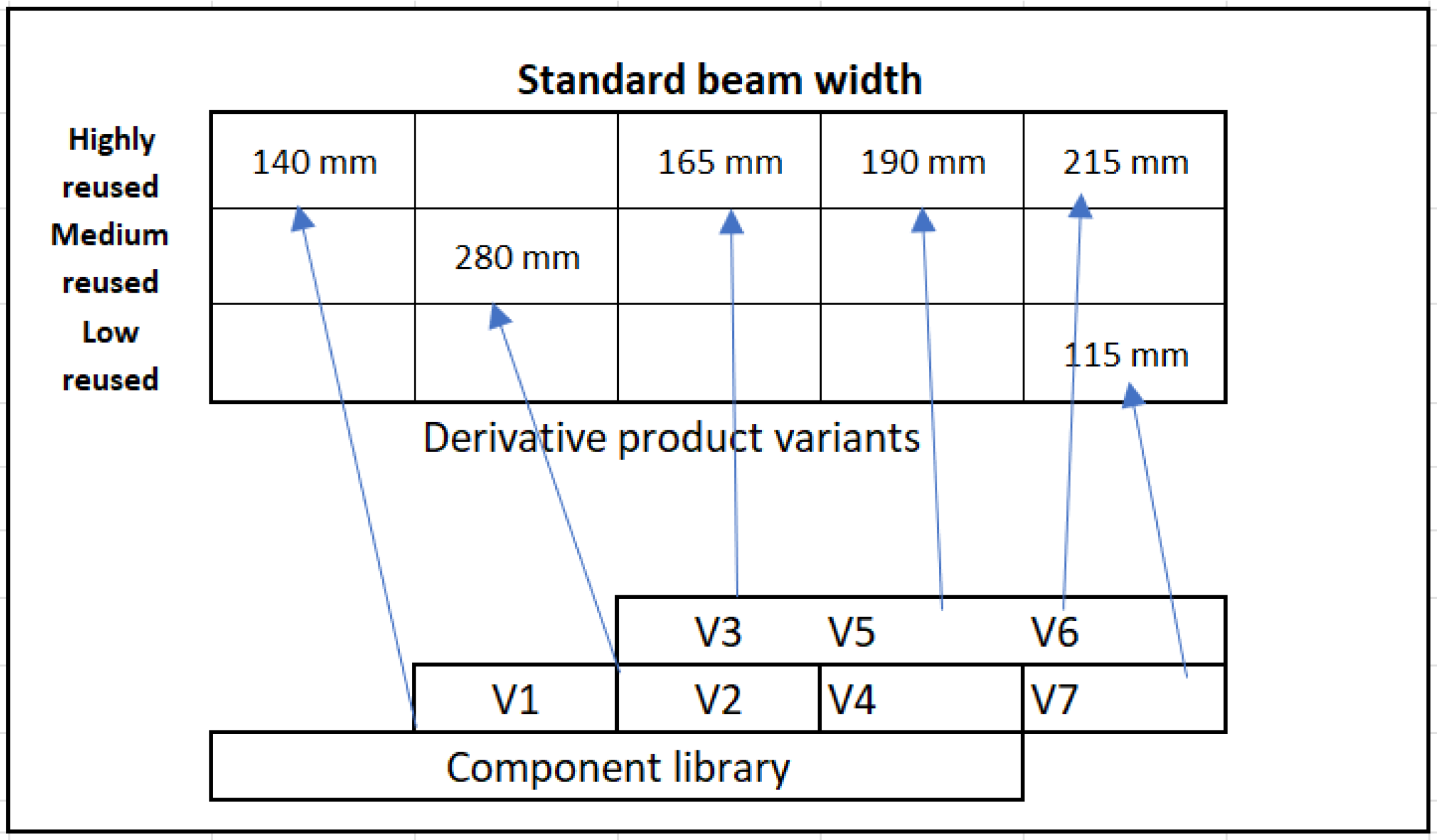
In this study, three previously completed projects were selected and analysed to identify the components variants that were suitable to include in the analysis. Then, the brackets were classified according to the degree of reuse in these three projects by creating a frame of product variants; see
Figure 3. The frame was divided into three segments, and the variants were classified into highly reused, medium reused, and low reused from the component library. This frame provides a clear idea about the standard beam width that has been commonly used in different projects and variants designed from that segment.
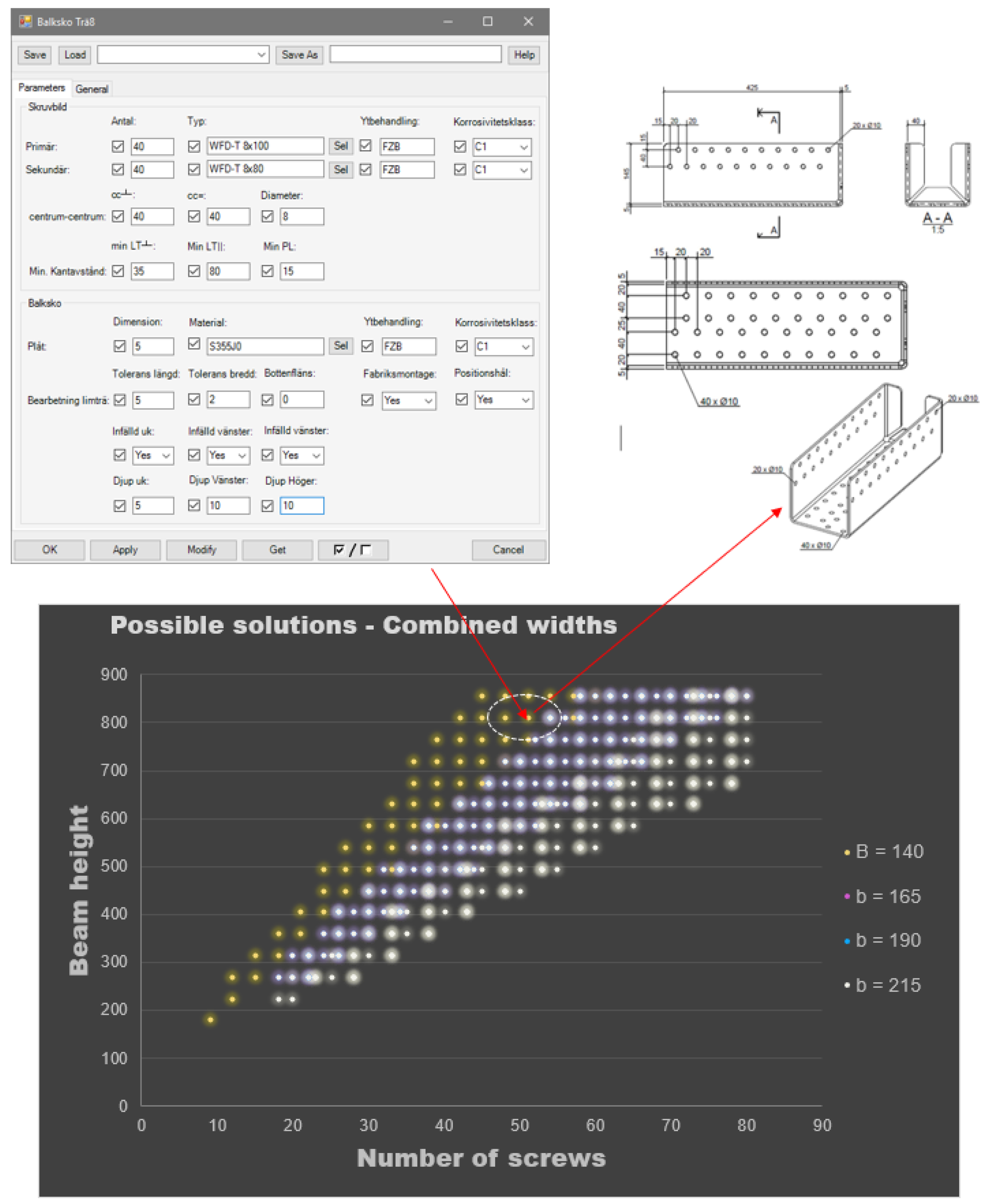
For this study, four standard beamwidths were selected; 140, 165, 190, and 215 mm, commonly used in the selected projects. From the previous design experiences, the designer also confirmed the occurrence of these variants in bracket design. The manual design of connectors is a time-intensive and complex process where geometry plays a significant role.
Therefore, a library must be created and effectively reused as the building design process requires considerable time. The senior design engineer from the case company created a component library in Tekla structures so that other designers can easily reuse it for different projects. This library comprises a set of bracket components that were used in different projects by modifying further manually to meet different project requirements. This was beneficial for performing this study.
After identifying the qualified component variants, the subsequent step was to compile the design elements and formalise the design assets of selected variants. Several project meetings and individual unstructured interviews were conducted to identify the tangible and intangible knowledge about the design of connectors, which was more focused on the know-how. This helped to identify the potential design elements and assets in the conceptual, system-level, and detailed design phase of bracket connectors. The project meetings served to create a common understanding for all key designers about the challenges and critical parameters both from a structural and modelling perspective.
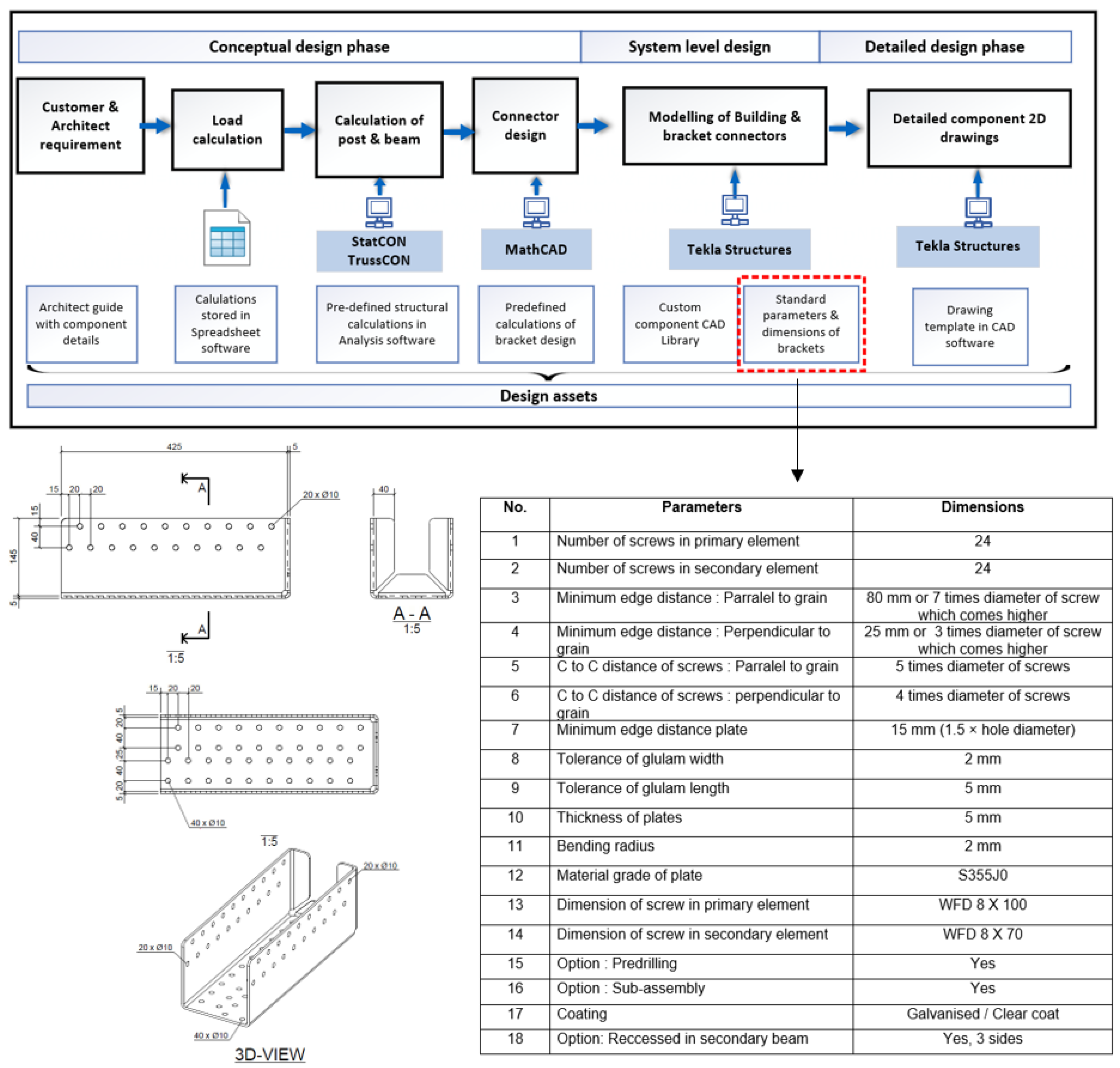
The design process for bracket connectors was mapped, and discussions were undertaken for individual steps as part of the process standardisation and asset identification.
Figure 4 shows the process involved in the bracket design and potential assets used in the three phases of the design process. The conceptual phase is mainly the structural design of the building, which includes load calculations, finding the dimension of post and beam, and finally the design of brackets based on previous estimates. The figure also shows different design assets that support this calculation process.
These implicit sources of knowledge about different design elements and assets were discovered from an in-depth discussion with structural engineers. For instance, a spreadsheet document was created to perform the load calculations and predefined in different applications to speed up the design process. These were developed by engineers from their tacit knowledge gained from the experience and explain the know-how of the bracket design. According to DPA, they are the potential design assets qualifying for the platform development [
3].
The system-level design includes the modelling of brackets where the focus of support development was placed. An example is shown in the figure where all the parameters essential for designers to perform bracket modelling are listed as well as the attributes used to describe and differentiate the bracket components. The table consists of both dynamic and constant value that governs the geometry of brackets under different design conditions and constitute the generic product structure of the bracket. The building blocks of the structures are then related to the different kinds of assets supporting their realisation, and these assets are used to develop product variant models based on individual customer requirements.
4.2.2. Creating Parametric Design Solution Space
In the previous steps, we identified the variants, design elements, and assets linked to those variants. Subsequently, this step refers to the predefinition of component and process knowledge to a platform and make it reusable. In other words, how the parameterisation of components was implemented and connected to the CAD software (Tekla 2020 SP5, Trimble Solutions Corporation, Espoo, Finland) to be able to systematise the design process.
The development of parametric geometry models has included explicit representation of all the design variables and standard parameters to the respective dimensions of the bracket connectors. Thus, parameterisation is made on geometric objects following a design logic to create the rules for the parametric features of the brackets. To accomplish this, different parameters were defined with rules, constraints, dependencies, and boundary conditions of which the values can change and generate different variants on each beam width while executing modelling.
The geometrical model of brackets is usually controlled through a set of input variables, such as the value of the horizontal and vertical load, the dimension of primary and secondary members and the number of screws on the members. The geometry of variants governs the change propagation for sub-variants where each input variable may directly or indirectly control several other parameters.
Thus, the acquired knowledge was formalised into a rule-based method that guides the design automation of system-level design or modelling of brackets [
25]. In this approach, alterations to any of the parameters defining grids or spacing can be automatically propagated to all the parts. These brackets are automatically sized to fit the beam width with predefined conditions. The changes made to any of the dependent parameters will result in the propagation of the change in the bracket height and number of screws.
Development of Design Solution Space for the Brackets
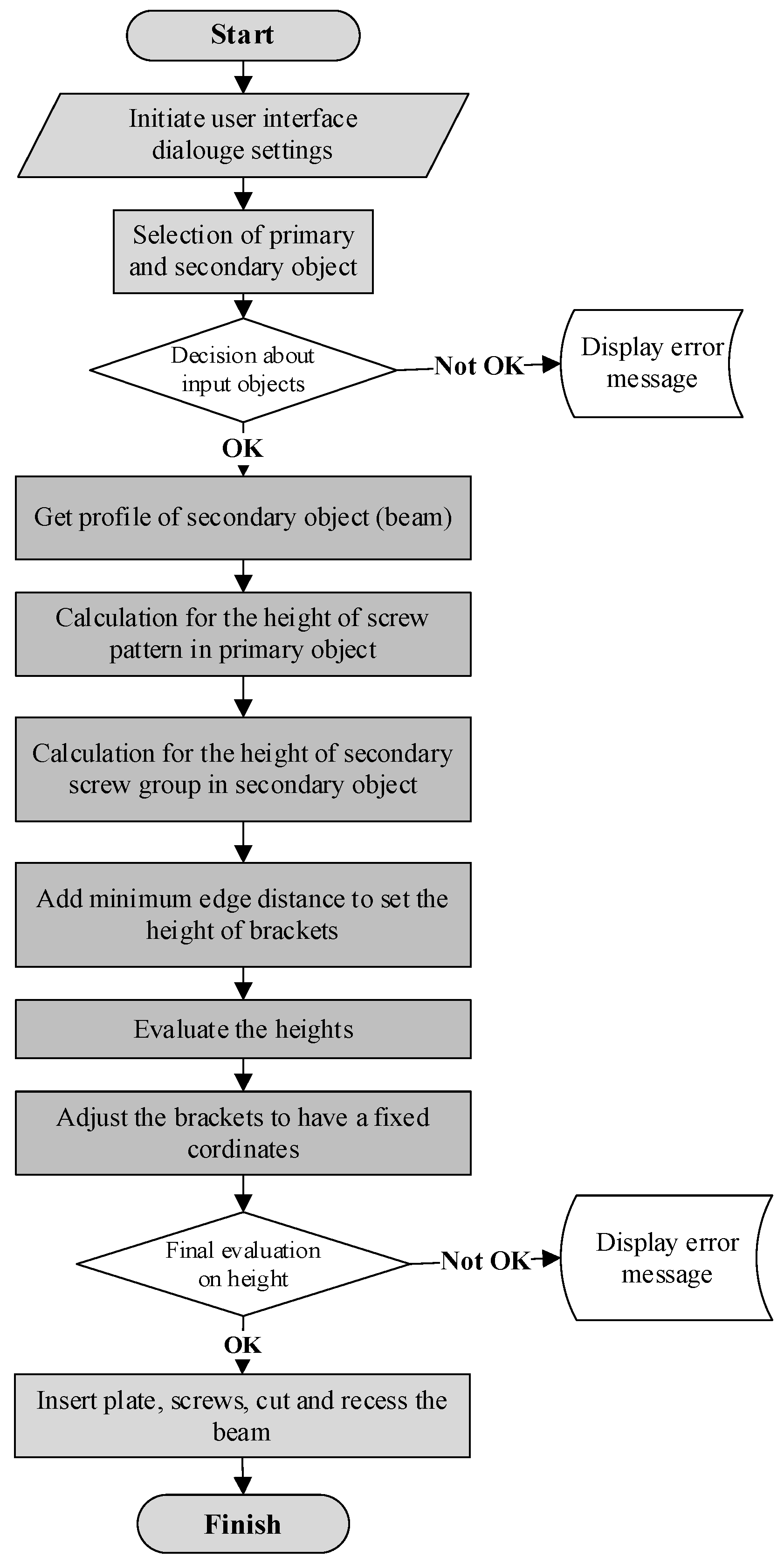
The following step was to develop a design solution space for the brackets, which is based on the formalisation of the geometrical knowledge essential to design the parametric model. The CAD software Tekla structures offer the automation of component modelling with the help of VBA and API. The logic flowchart for the development of design solution space and how parameterisation functions are shown in
Figure 5. This logic was developed by the researcher together with the support of a senior design engineer that explained how the algorithm follows the modelling of the bracket.
The first step of the coding starts by initiating the user interface (UI) dialogue for designers to interact with CAD software (Tekla) while designing different bracket solutions. The UI provides the window for configuring various sets of bracket solutions based on different requirements in projects.
Designers should define the input parameters that include both a constant, material, coating, class type, etc., and varying parameters: the number of screws in primary and secondary objects and information about the type of screws in primary and secondary used for the bracket connection. The plate thickness and diameter of screws are critical values for the bracket design. Here, the primary object refers to the post, and the secondary object is the beam profile.
The selection of a primary and secondary object in the model by the user is the following step. Here, the material type must be verified for both primary and secondary objects by which the algorithm validates that the objects are made of timber. It was coded to show an error message if the objects are not made of timber.
If the material is verified as timber, the following process is to see how many secondary objects were selected by the users i.e., only one or several. The subsequent step is to check if the primary and secondary objects are perpendicular to each other. The decision about the geometry is an important step, and the connection will not be accurate if there is an inclination between the objects. The code is predefined to show errors if the objects are not perpendicular to each other as shown in the flow chart.
The following step is to find the profile of the secondary object (beam) where the algorithm requires the width of the beam for successive actions. Once the profile is known, the system calculates the heights depending on the number of possible row configurations for the primary screw group. First, a decision has to be made on how many vertical rows can be fit in the primary beam depending on the width of the beam. Then, the calculations can be performed for different heights by dividing the number of screws inserted into the UI. The screw group is variable and used to evaluate the secondary beam width to height. This provides a set of heights, which are then evaluated.
The condition is as follows.
The calculation of the number of possible vertical rows of screws in the secondary object is the subsequent step depending on the width of the beam profile selected. Here, the number of possible configurations is examined. For example, how many rows of screws can be possibly fit with that beamwidth. Changes can be made automatically if the structural engineer executes any late changes even after the modelling was completed.
This is an advantage of using this approach in the modelling phase over the manual modelling of brackets. The next step is to add a minimum plate edge distance to the set of heights configured above. For this purpose, a set of heights for the entire bracket can be calculated. Then, an evaluation has to be conducted to compare the suitable height of the primary and secondary object that fulfil the following conditions:
Here, the tolerance is very important, and the height of brackets should not exceed the height of the beam. If the algorithm is not defined to create a valid height, an error message will appear to notify the designers. If more than one solution exists, the system uses the one with the lowest utilisation of material. Moreover, an error message appears if no solution arises. When the calculated height is ready, the next step is to adjust the bracket to have a fixed location of the topmost screw in the column. This is an important step to avoid the collision that could happen between screws from other directions in the primary objects.
A final evaluation should be conducted again to decide the new height according to the criteria above. The final step is to insert the plate, screws and cut the beam to length, and create recesses. This results in the configuration of the bracket connector based on the input provided by the users. The designers can perform the process iteratively as the algorithm wait for the next input parameters to create another bracket. This is how the knowledge assets define every feature of geometry of sub-variants and their relationships and form the design solution space. Thus, the design space defines the degree of freedom within which the range of component variants are located and the boundary up to where the designers can pick required solutions.
4.2.3. Testing and Evaluation of Solution
To ensure reliable automated modelling of bracket connectors, testing and evaluation of different variants predefined in the solution space were conducted. The bracket variants chosen in the first stage are evaluated in this step concerning the expected flexibility they offered to individual beamwidth. The designer followed four main steps while testing the parametric modelling approach in CAD modelling software:
Select the primary member.
Select the secondary member.
Add the number of screws in the primary and secondary members.
Select the type of screws.
These parameters are the input values provided to the UI dialogue box.
Figure 6 shows the combined view of the UI window where designers provide input parameters, potential solutions picked from defined solution space, and finally the variant generated. The flexibility in the variants can be achieved with the help of a predefined algorithm by carrying out module division on the design parameters of all variants under the same beamwidth.
Based on this, similar configuration structures of beam widths are integrated into the solution space. Here, the variants family adapts to different inputs on primary and secondary objects and can be quickly designed by utilising existing module configuration or adjusting the variant parameters or adding and modifying the customisation parameters; therefore, a quick configuration can be derived.
4.2.4. Comparison between Manual and Parametric Modelling
A time study was conducted to perform a comparison between manual modelling and parametric modelling based on the proposed approach. Tekla structures were used as CAD-software for modelling the brackets. The process steps involved in both manual and parametric modelling can be seen in
Table 1.
The testing commenced with the manual modelling first and the time taken for completing the whole bracket design was recorded. The modelling of a specific bracket variant from 140 mm beam size was selected for the testing, and it took 20:50 min to complete the manual modelling as shown in the table. This task helped to gain an enhanced understanding of the design process and verify the formalised design elements and assets for method development.
After completing the manual modelling, designers demonstrated the parametric modelling of the same variant where it took only 56 s to add the bracket component to establish a connection. The parameters were then modified—for instance, the number of screws in the primary and secondary dimensions of bolts, materials, etc.—to show how the automation in design was accomplished. The beam profile can also be altered if needed, and the brackets automatically adapt to the required geometry. The results show that parametric modelling is approximately 20-times faster than manual design starting from scratch.
Thus, implementing the proposed modelling approach positively impacts the design lead time as the company builds five to eight projects every year and designs on an average of 200 brackets from seven to eight variants for each project. The experiment proves that the method is beneficial for the company even though designers use support from a custom component library and make a practical contribution. The time for both manual and parametric modelling was recorded and discussed in the project meeting to show the benefits of implementing the method. Moreover, the findings on critical success factors of IHB design from Thajudeen et al. [
44] were used as a baseline for evaluating the application and use of the method as shown in
Table 2.
5. Discussion of Findings and Development of the Method
The purpose of this study was to devise a means to support the design process of ETO-based components in IHB. The findings from the detailed study on bracket have shown the opportunity for developing a method to support the reuse of design assets drives to platform development in the ETO context.
5.1. Parametric Design Platform to Support ETO Building Components
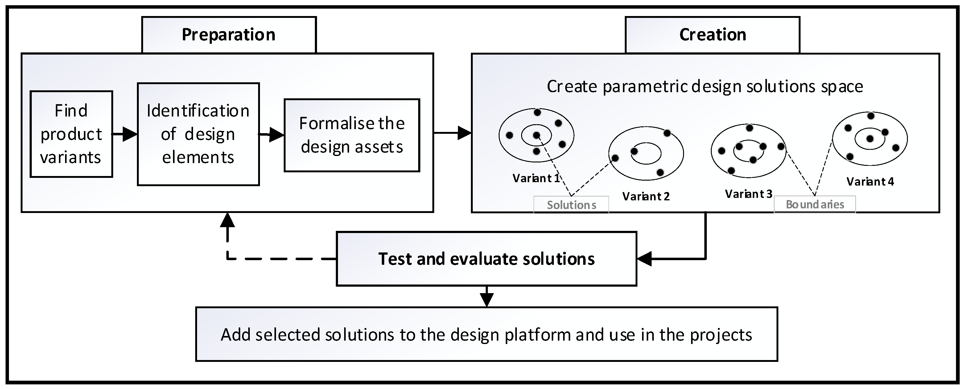
A parametric design platform method is proposed to support the reuse of design assets associated with ETO-based building components in IHB, thereby, fulfilling the purpose of this study. An overview of the proposed approach is shown in
Figure 7, consisting of three stages: preparation, creation, and evaluation. The design processes of IHB can be divided into three phases: the conceptual phase, the system-level phase, and the detailed design phase.
The proposed approach is suited to serve the system-level design phase where designers are modelling the building with the help of a CAD program. This approach is developed based on the motivation gained from the literature study, more specifically the design platform model developed by André et al. [
17] as well as the observations and experiences shared by the designers during the empirical data collection.
This study adopts a distinct approach by concerning the reuse of assets as a naturally occurred process while developing a building component and can be improved by adopting a practice of documenting design knowledge. Thus, the concern was to identify and formalise the design assets that can be reused during the system-level design process and to support the designers to improve the design process.
Preparation: As shown in the figure, the first step consists of three parts. Companies offering customised products often identify and predefine the knowledge and experiences gained from the product development process. Thus, the first part begins by identifying the existing design of desired product variants that can fit into the boundary of the intended platform.
The repetitive design activities are routine and consume more time, which is suitable for automation, and the formalisation of knowledge about product variants are simpler since they usually handle explicit information and knowledge [
45]. This is because the designers can begin from an existing solution, which they already created, and carry out further customisation. The variants are generated from a generic product structure and designers stored the geometry of variants in a library to a great extent to reuse [
37].
The following process is to identify the design elements (DE) and formalise the design assets (DAs) connected to the selected product variant family. This part of the method is coined with the definition of DPA introduced by André et al. [
17], which supports the generic modelling of a product platform using the design assets and product structure. According to the authors, DEs refer to a piece of knowledge about the product and design process, including all activities during development.
Design assets can be defined as a collection of assessments, guideline, constraints, processes, and geometric features [
16]. The main focus of the PDP approach is to further explore the geometry resource part of the DP model, namely the parametric CAD models that can span a design solution space. From a platform perspective, it is possible to reuse all these design assets predefined concerning a product while executing design activities [
3].
Creation: The following step is to create a parametric-based design solution space with the selected component variants and formalised design assets [
36]. A parametric modelling method shows which attributes of a geometric pattern are parameterised and how the values of the parameters can be changed by the designer. Here, the acquired design knowledge of different qualified product variants can be formalised and predefined with a rule-based approach that leads to the automation of the process. To succeed in design automation, KBE methods can be utilised to efficiently capture knowledge by storing rules, relations, and facts [
20].
The design variables and functional attributes include standard parameters, dependencies, and constraints that govern different design conditions can be represented in the form of an if-then-else statement. This step catalyses the establishment of the relationship between different attributes. The parametric approach, implemented with attributes and topological relations, characterises how parts will interact with one another in support of their function [
22,
34].
This supports the capability of evaluating a model against different component parameters against customer requirements or design rules to ensure that the building meets the relevant functional and geometric requirements while designing. Coding the design knowledge within a template model gives the ability to standardise and automate the routine process in design and, therefore, control the flexibility within fixed, well-defined boundaries [
34].
This can be viewed as the parametrically driven design platform for a particular building component flexible to various design settings. Here, the degree of design freedom and solution space can be expanded based on the additional requirements during the realisation of a specific product solution. This is because the developed platforms evolve to keep the customer′s happiness in terms of technical, functional, and structural aspects.
Evaluation: Finally, testing and evaluation of the created parametric solutions should be performed by designing different product variants under several conditions. The evaluations are a crucial part of providing input to the exploration approach in the form of metrics and potential sources of visualisation of each solution [
37]. Moreover, this information serves as a foundation for decision-making and a guide to the solutions generator. The selected solutions can be added to the design platform as geometry resources and used in different projects or modified by following the steps again. Lastly, the developed solution space should be maintained and iterate the same process to add more variants.
5.2. Discussion of Method
This research expands the knowledge of DPA presented by André et al. (2017) through integrating the parametric functionality and reuse of design assets resulting in a parametric design platform. It helps to identify and describe engineering assets residing in a company as a formalised method that can be supported by IT applications. According to this study’s findings, by integrating the parametric modelling approach, it is possible to shift the engineering strategy gradually from ETO to CTO strategy, which claims the novelty of the study.
This supports companies to be more efficient in the design process and manage the challenges caused by customisation. Thus, by reusing the engineering assets, the ETO-based components can push the boundary towards the adoption of the configuration of variants from those components [
25]. This initiates the incremental development of platform-based design in a firm. However, understanding the complexities drivers involved in the design process of the ETO-based component is crucial when moving towards a CTO or MTO approach.
The formalisation of design assets is considered to be an important medium for transferring knowledge [
15]. However, it is important to maintain the developed knowledge platform to serve solutions for fluctuating needs and facilitate automation of component modelling. The developed platform may evolve as the solution space and defined boundary conditions could be expanded owing to the addition of component knowledge to serve future needs from customers.
Therefore, it is essential to ensure a satisfactory level of documentation of design knowledge and management of CAD models [
36]. The findings also support the study conducted by Banihashemi et al. [
22] in terms of waste reduction in the design workflow and Salvador et al. [
38] as a tool to facilitate mass customisation with robust design and solution space development.
The method proposed in this study utilises the potential of parametric modelling and enables the reuse of design assets in the system-level design phase. The established approach can store the generated knowledge when a new variant is developed and then reuse it to help the designer improve the value-creation in the design process, which is congruent with the KBE method [
20]. This was designed to identify key design elements, formalise the connected assets (the ones that are highly responsive to component variant attributes), and enhance flexibility to those elements [
26].
Here, the term ‘flexibility’ refers to the ability of the developed solution space represented as a platform to support a wider range of customised designs and variants of building components [
23,
26]. To deal with later changes made by structural engineers due to the addition or removal of structural deviations, flexibility needs to be retained so that designers who modelled the component can be easily changed until the requirements can be considered finished [
27].
The identification of appropriate design solutions is based on a proper exploration of the solution space of the design task [
37]. To define the best-suited design spaces for component functions, the platforms were developed based on the logic of constraint-based development [
36]. While solving a design dilemma, designers are using various kinds of tacit knowledge. Knowledge embedded with an experienced designer is an asset to a company.
Formulating design intentions with parameters and explicit functions requires a different way of thinking that most designers are not familiar with in their daily activities. However, in construction, it is important to make it explicitly available for all designers to follow and use in designing complex components. Rule-based systems provide a means to capture the knowledge of human experts.
The case study demonstrated that the proposed method offers a potential means for automating the design process when dealing with highly customised solutions. The method was demonstrated through a time study, and outcomes were discussed with the designers at the case company and accepted as a support for strengthening the knowledge asset and reducing design lead time. This benefits the designer in their routine activities and encourages them in developing parametric-based solutions as a tool, which is essential for IHB companies to deal with emerging needs from the market.
The key to improving the design efficiency for customised building components is to understand the critical parameters and the behaviour of variant geometry. In the case of bracket connectors, a change in the beam dimension or floor height results in generating variants. Thus, controlling the number of variants of building components can be considered an element of business success. The analysis shows that the complexity can be reduced if the beam size can be controlled as the variants are generated mainly based on the beamwidth.
The PDP approach supports the exploration and generation of design solutions to systematically maintain product quality and standardisation while enabling continuous improvement. Although the parametric modelling approach has been introduced to the construction sector for decades, it is anticipated to achieve its full potential subject to readiness in the industry. In light of these benefits, IHB companies can encourage their designers to adopt this method when dealing with ETO-based components.
The proposed method developed based on the findings from the case company supports the overall knowledge contributions. The approach is a synthesis between parametric modelling and DPA to create a flexible platform for ETO building components in IHB. Thus, the academic contribution consists of adding and expanding to the body of knowledge regarding the use of product platforms in IHB and how flexibility can be achieved by introducing the PDP approach. The industrial contribution consists of supporting the companies with a novel practical approach for designing ETO-based components by identifying, formalising, and reusing design knowledge to initiate incremental steps towards platform-based development.
The generalisability of this study is limited as the results are based on a single case. However, this research builds upon the existing DPA approach, and the applicability of DPA has already been tested in element and volumetric type IHB companies [
3,
5] that offer complete solutions to the customer as turnkey projects. This study has extended it with a practical method to improve the modelling of ETO-based components.
The novelty of this study is that the approach was tested in a different kind of IHB system, which is a system supplier of building components, and the results show a path forward for platform development in IHB. By following the steps presented in
Figure 7, the proposed approach can be used to design ETO-based components in any building system that offers customised solutions with further evaluation.
The selected case can be considered as the best example where this approach can be applied, as the project’s requirements are unique and vary constantly where the proposed PDP method support designers to become efficient in the design process. The interviews make it obvious that the key strategy to achieve a design configuration is connected to the reuse of knowledge assets, which also ensures that most of the bracket variants can be managed by the PDP approach.


