Article

Effect of Needle Type, Number of Layers on FPAFC Composite against Low-Velocity Projectile Impact

1
School of Civil Engineering, SASTRA Deemed to Be University, Thanjavur 613401, India
2
Civil Engineering Department, Wasit University, Kut 52003, Iraq
3
Peter the Great St. Petersburg Polytechnic University, 195251 St. Petersburg, Russia
4
Polytechnic Institute, Far Eastern Federal University, 690922 Vladivostok, Russia
5
Department of Civil Engineering, College of Engineering, Prince Sattam Bin Abdulaziz University, Alkharj 11942, Saudi Arabia
6
Department of Civil Engineering, Faculty of Engineering and IT, Amran University, Amran 9677, Yemen
*
Author to whom correspondence should be addressed.
Buildings 2021, 11(12), 668; https://doi.org/10.3390/buildings11120668
Submission received: 23 November 2021 / Revised: 14 December 2021 / Accepted: 14 December 2021 / Published: 20 December 2021

Abstract

:
Protective structures subjected to intensive loads that may benefit from the use of multilayer composite structures with excellent hardness and impact resistance represent an emerging research field in recent times. In this study, low-velocity projectile impact tests were performed on Functionally-graded Preplaced Aggregate Fibrous Concrete (FPAFC) mixtures to evaluate their performance. The effects of projectile needle type, fibre type and hybridization in addition to the number of layers in the composites on projectile impact were investigated. The bioinspiration of the excellent impact strength of turtle shells was used to design an FPAFC comprising a higher amount of steel and polypropylene fibres at the outer layers. In parallel, one and two-layered concretes were also cast to assess the effectiveness of three-layered FPAFC. The tests were performed on disc specimens using non-deformable compound bevel, convex edge and hollow edge projectiles. The damage severity was quantified by the top damage area, bottom damage area and depth of penetration. In addition, a simple analytical model for predicting the composite mass expulsion was developed and implemented. Findings indicated that regardless of fiber type and distribution, the compound bevel projectile needle produced the lowest impact numbers for all single, double and triple-layer specimens compared to the convex edge and hollow edge projectiles. Repeated projectile impacts increased the penetration depth and damaged area at the top and bottom surfaces of all targets. Targets were more resistant to convex edge and hollow edge projectile penetration than the compound bevel. The experimental and analytical model results for mass expelled from the top surface are reasonably acceptable. This research gives an idea of developing advanced fibrous composite with superior impact resistance for the promising protective structures.

1. Introduction

Structural composite materials inspired by biology have attracted significant interest in recent times due to their impressive mechanical properties and innovative hierarchical structures [1]. An exceptional amalgamation of biological composite structures (e.g., the turtle shell) with improved mechanical properties can be attained and used for penetration resistance. These impressive mechanical properties are the consequence of their structural composition and organization. Differing from artificial physical copied materials, such complex structures comprising woven components of organics and inorganics that have hierarchical organization at different scale levels (nano-, micro- and meso-) [2]. Exploring the performance of biological systems and materials allows scientific experts from materials science to develop designs inspired by biology. This research area falls under the name of biomimetics, which is classified among the emerging concepts in materials science. In Nature composite structures with a different hierarchy (natural armour) that can withstand a diverse range of penetration events exist in several animals. Abundant literature has reported on the mechanical performance of biological composite materials such as bones [3], crustacean exoskeletons [4], bird beaks [5] and seashells [6]. The turtle shell vigorously protects the animal from environmental penetration events and impact loading, while also ensuring flexible mobility due to its multiscale hierarchy. Figure 1 illustrates the sandwich-type carapace shell of a turtle [7]. The turtle shell comprises three layers; the first layer is very dense, covered with a horny keratinized scutes layer, delivers armour defense and is called endocortical; the second layer is trabecular, which is porous and serves as an impact absorber. The third layer is very dense and is called exocortical, and imparts shielding protection [7]. The fibrous structure within the cell is indicated clearly in the SEM micrographs (Figure 1). This turtle shell offers excellent armor defense and inspiration to use the endocortical layer to prevent penetration and the trabecular layer to absorb impact energy. The excellent resistance to impact and penetration events of biomaterials is due to the divergences in their systems and structural composition.

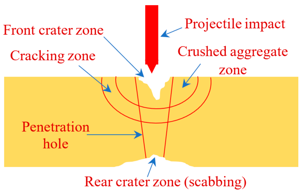
Projectile Impact on Concrete

Concrete is a traditional construction material that is applied widely for defense and civil applications such as protective structures, infrastructures, bridges and buildings [8,9,10]. These structures can experience impact loads periodically in the form of gunshots or blast loading. A bullet-type impact force that strikes a concrete structure results in two tactical damages anticipated in the event of a gunshot. The bullet impact force directly causes the first damage. Since bullets are smaller pieces than the concrete targets and tend to pierce the target at the point of contact, localized damage generally occurs in the form of perforation or penetration damage [11]. The indirect second damage occurs due to flying broken concrete pieces or debris in various directions. Due to impact loading, cracks are induced that can proliferate rapidly and result in catastrophic failure. To develop a concrete with a high impact resistance, the energy absorption and ductility must be enhanced. The utilization of fibres is likely to increase concrete ductility and reduce its brittleness [12]. The presence of fibres helps interrupt cracks and slow down their spread [13]. The resistance of fibrous concrete to impact relies on several factors: concrete strength, fibre dosage, fibre geometry and fibre type. In recent years, fibres with various kinds and geometries are commercially available [14,15]. When it comes to concrete reinforcement, a wide range of fibres may be employed. These include natural, polypropylene, polyvinyl alcohol, basalt, glass and steel fibres. Diverse kinds of reinforcing fibres would have varying effects on increasing the effectiveness of the concrete, and they might also impart varying characteristics to concrete. As an instance, the addition of high tensile strength fibres such as basalt and steel fibre would not only enhance the concrete’s tensile strength but would also augment its energy absorption capacity and toughness [16]; steel fibre exhibits excellent impact resistance [17]; carbon fibre can improve magnetic sensitivity, pressure sensitivity and electrical conductivity concrete [18,19,20]. Wu et al. [21] reported that employing larger aspect-ratio steel fibres would result in improved interaction between steel fibres and concrete matrix in contrast to smaller ones. This phenomenon is due to steel fibres with a smaller aspect ratio having a lower efficiency in bridging macrocracks. This may be explained by the fact that when microcracks transform into macrocracks, more steel fibres are pulled out of the matrix, which results in less efficiency in bridging macrocracks. The steel fibre dosage is usually limited in traditional fibre reinforced concrete to 2% due to workability issues and to ensure uniform fibre dispersion. Higher fibres dosages in concrete (i.e., exceeding 2%) tend to create fibre clustering. Balling creates faults, weaknesses, and voids, leading to additional microcrack formation, reducing the compressive strength [22]. Steel fibres were found to more effective that other synthetic fibre types [23]. The anchorage effect is increased by using end deformed or fully deformed steel fibres and this significantly enhances concrete toughness [24]. For a particular kind of bullet impact on concrete that should meet the no-perforation need, fibrous concrete was displayed to be adequate in withstanding this type of load. The available literature indicates that concrete mixtures with high dosages of steel fibres can help enhance the energy absorption capacity, where the steel fibre pull-out and concrete damage can absorb the enormous energy released during impact [25]. In a highly evolved concrete technology, a series of novel materials with superior properties exists in the construction sector. These novel materials provide a creative concept that has higher impact resistance performance than conventional concrete. Depending on the needs of strong composites, the developed concept of functionally graded fibrous concrete intended to deliver a superior impact resistance by changing the properties along the depth of concrete and it can be a suitable candidate to be usefully applied in protective structures.
Several studies have been performed on the projectile impact performance of functionally graded fibrous concrete. For instance, Quek et al. [26] revealed that functionally graded panels displayed much better resistance to impact than plain mortar targets. Furthermore, the disintegration of all functionally graded panels occurred when the velocity of the projectile surpassed 300 m/s. The functionally graded panels experienced minor damage at the front face with considerably less crater diameter and evidenced its high potential in lessening penetration with increased thickness of layer. Moghadam et al. [27] investigated functionally graded self-compacting fibrous cementitious composites slabs against drop weight and projectile impacts. The slabs were reinforced with steel and nylon fibre amalgamations of 1% fixed dosage. The results indicated that functionally graded slabs containing steel fibres showed very effective resistance to projectile impact compared to traditional fibrous concrete slabs, where the destroyed volume and penetration depth were significantly reduced in functionally graded slabs. Mastali et al. [28] indicated that a significant reduction in back destroyed area, front destroyed area and penetration depth was observed in five-layered functionally graded fibrous concrete slabs compared to traditional fibrous slabs even though both slabs comprised equal amounts of fibres. Lai et al. [29] reported that the hybrid fibres restrained the crater diameters and cracks at the front surface layer. At the same time, multiple penetrations were restrained by the middle layer comprised of ceramic aggregate and steel fibres. No spalling or cracks appeared on the rear side of composites due to the existence of steel fibres.
The most reliable way to evaluate penetration damage parameters is through the experimental observation. Several studies have been performed to examine the penetration mechanism. Canfield [30] investigated the penetration resistance of concrete with different dimension projectiles. The findings indicated that the penetration depth exhibited a linear trend of rising with the increasing of impact velocity. Forrestal [31] studied the penetration process of concrete targets against different projectiles. The strength of targets differed from 13.5 to 62.8 MPa and the projectile impact velocities varied from 100 to 1300 m/s. Experimental results showed an unsteady penetration regime in concrete target with a corresponding impact velocity of 1200 m/s. Wu et al. [32], Mu et al. [33] and Guo et al. [34] examined the impact performance of concrete targets subjected to steel projectiles and the results showed the projectile failure with a deformed state. Nia et al. [35] and Gold et al. [36] investigated the penetration behaviour of concrete targets using copper and tantalum projectiles. The compressive strength targets ranged from 37.4 to 65.6 MPa and the velocity of impacts varied from 1400 to 1900 m/s. Results showed an eroded residual projectile at the time of penetration.
The reviewed research results were about the impact properties of fibrous concrete targets against single hits of high-velocity projectiles. The behaviour of fibrous concrete against multiple hits is an area lacking complete investigation. In this research, a three layered FPAFC with a higher impact resistance based on the bionic inspiration of turtle shells was introduced. Preplaced aggregate fibrous concrete (PAFC) casting technique was used to produce all FPAFC. PAFC concrete is an innovative, fibrous concrete with diverse fabrication method. Initially, the premixing of fibres and coarse aggregates is done and the mixture is filled into an empty mould. This fabrication method allows more fibres and coarse aggregates to be packed in the mould and facilitates interlocking, thereby forming a natural skeleton followed by grout injection. The recent researches state that PAFC shows exceptional mechanical properties [37], lower drying shrinkage and creep [38], elevated temperature resistance [38] and high impact resistance [39,40]. The developed FPAFC specimens were subjected to the three different shapes of projectile impact. Moreover, a simulation model was used to predict the ejected mass during the penetration and compared with the experimental results.

2. Significance of Study

Recently, a large number of scientific investigations have been performed to enhance the projectile impact resistance of functionally graded and other fibrous composites subjected to high-velocity impacts. Thus far, a limited number of investigations to evaluate the impact resistance of this composite against the different shapes of projectiles and repeated low-velocity projectile impacts has been completed. It is of an immense significance to develop a bioinspired functionally graded fibrous concrete using the concept of preplaced aggregate concrete casting technique. The FGPAC specimens were constructed with three layers comprising a higher dosage of fibres in the top and bottom layers. At the same time, one and two-layered composites were also constructed for comparing the effectiveness of the three-layered FGPAC. A new type of steel and macro polypropylene fibres was used with different fibre schemes (mono and hybrid combinations) and dosages. The effect of projectile type on the concrete composites was studied extensively by considering three projectiles: compound bevel, convex edge and hollow edge. All concrete composite specimens were tested against low-velocity repeated projectile impact. Their damage severity was quantified by the front damage area, rear damage area and penetration depth for every four impacts. Besides, the effects of fibre type, fibre hybridization and number of layers were also studied extensively. The research-based on this theme is still unexplored and requires a considerable attention. To fill this research gap, a new FGPAC is proposed and its low-velocity repeated projectile impact resistance was investigated in this study.

3. Materials and Methods
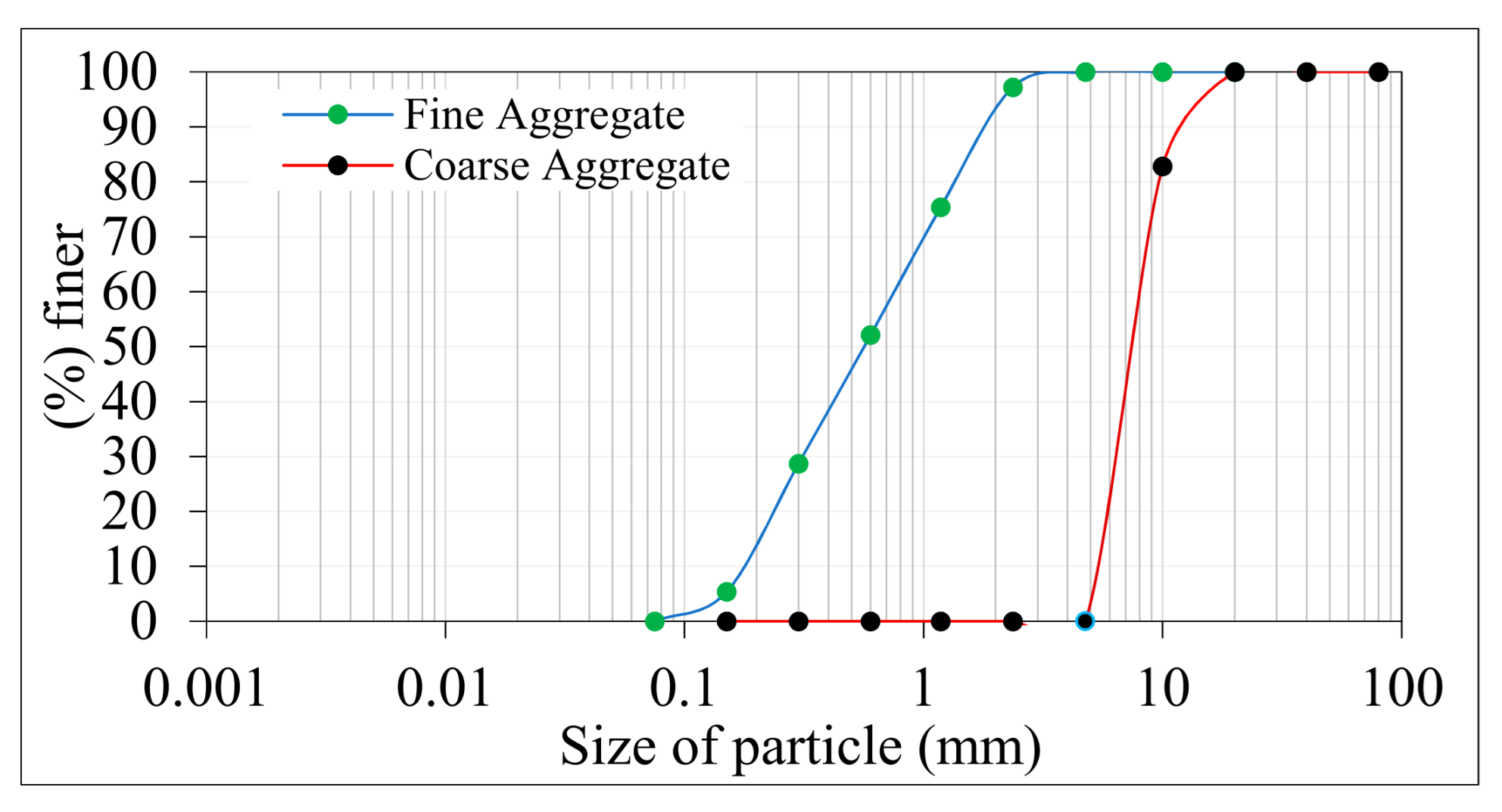
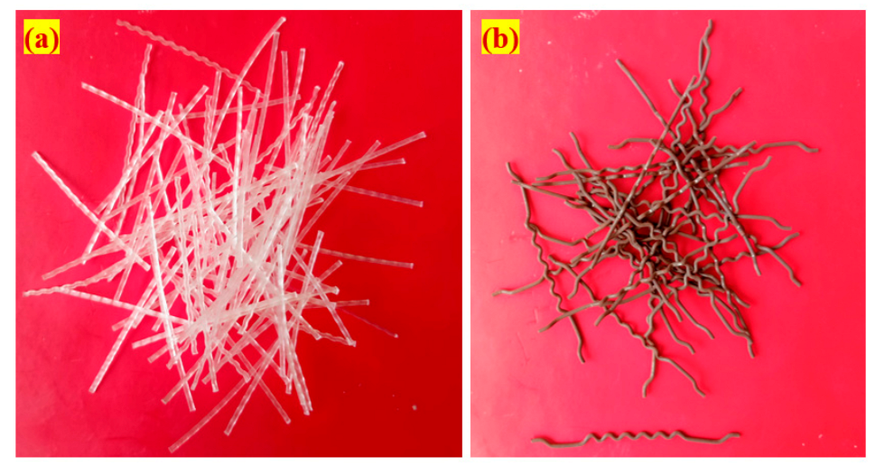
3.1. Raw Materials

In this research, the cement utilized in was Pozzolana Portland Cement produced in accordance with IS:1489-2015 [41]. The blain fineness, standard consistency, specific gravity, initial and final setting time of cement were 375 m2/kg, 30.8%, 3.14, 32 and 550 min, respectively. The fine aggregate utilized was natural river sand sourced locally with a fineness modulus and specific gravity of 2.41 and 2.65, respectively, in conformity with IS:383-2016 [42]. The size of fine aggregate was not exceeding 2.36 mm, confirming obtaining better flowable grout according to ASTM C939/C939M-16a [43]. Henceforth, a splendid flowable grout under gravity infiltrated into the voids existing in the fibre aggregate skeleton. Natural gravel with a particle size of 12.5 mm was utilized as coarse aggregate. The water absorption, specific gravity, and apparent bulk density of the coarse aggregate were 0.56%, 2.6 and 1700 kg/m3, respectively. Figure 2 illustrates the granulometric curve for the used fine and coarse aggregates.
A commercialized fluidifier admixture known as Tech mix 640 was utilized to reduce the amount of mixing water required and extend the grout fluidity as per IS 9103:1999 [44]. A grout fluidifier contains a water-reducing additive in most cases, with a recommended dose of 1% by weight of cement [45]. The water-reducing admixture dose was kept at 0.4% in this research to provide excellent flowability, fulfill efflux time requirements and avoid honeycombing. Two new different types of fibres were used to improve the tensile strength of concrete. The first was a hybrid hooked end-crimped steel fibre (SF) with a diameter of 1 mm, length of 50 mm and tensile strength of 1150 MPa. The second was macro polypropylene fibre (PF) with a diameter of 0.8 mm, length of 45 mm and tensile strength of 500 MPa. Figure 3 depicts the appearance of two different fibres that were utilized in this research.

3.2. Mixing Composition

In this research, the ratio of cement to sand was 1.0 and the ratio of water to cement was 0.45 which were optimal for the casting of the twelve different composite mixtures. In order to fill the existing voids in the natural skeleton comprised fibres and aggregate, a high-quality admixture (water reducer) and fine sand were combined to produce a free-flowing cementitious grout. Several pilot experiments were carried out to optimize these ratios and produce FPAFC mixtures that would satisfy the efflux time of 35–40 ± 2 s [45], which was the goal of the research. The tensile properties of the two fibres were taken into consideration throughout the selection process. The SF was chosen for its high tensile strength as well as its high density. The low density and low tensile strength of the PF led to its selection as the second fibre. Specifically, the effects of mono fibre (SF, PF) and hybridization of fibres (SF + PF) have been investigated in this study for detailed technical investigation. Low-density fibre use resulted in a 2.4% average dose of fibre given in three layers. The PF content was optimized to fulfil the mixture requirement, where the required quantity of aggregates could not accommodate into the formwork when a greater dosage of PF with low density was used, which led to produce a slurry-infiltrated fibrous concrete rather than the required prepacked aggregate fibrous concrete. In order to prevent the production of slurry-infiltrated fibrous concrete, the average fibre dose in this research was restricted to 2.4%. The first of the twelve mixtures was made using preplaced aggregate concrete and was designated as the reference sample (PAC). Single-layer PAFC was used to produce the second and third mixtures, which included 2.4% dosage of PF and SF, respectively and designated as S-SF and S-PF, respectively. The fourth mixture was produced using the idea of a two-layer FPAFC with SF and PF at the top and bottom layers, respectively, while PF and SF were used at the top and bottom layers for mixture five, which was also a two-layer one. Hence, for mixtures four and five, the same quantity of fibre was used, but the direction of the fibre was reversed. D-SF-PF and D-PF-SF were the designations given to mixtures four and five, respectively. The remaining mixtures were produced using a three-layer FPAFC approach, which included various fibre dosages in each of the top, middle and bottom layers, in order to determine the optimum fibre amalgamation for good resistance to impact. Table 1 shows the mixing components of the twelve mixes that were utilized in this investigation. The fibre reinforcing method utilized to construct the FPAFC specimens is shown in Figure 4 and the casting technique was applied layer-by-layer.

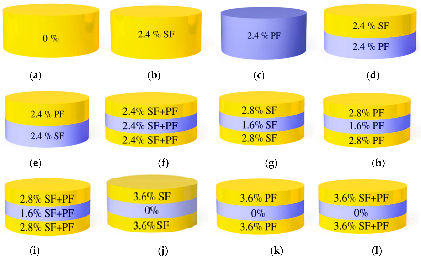
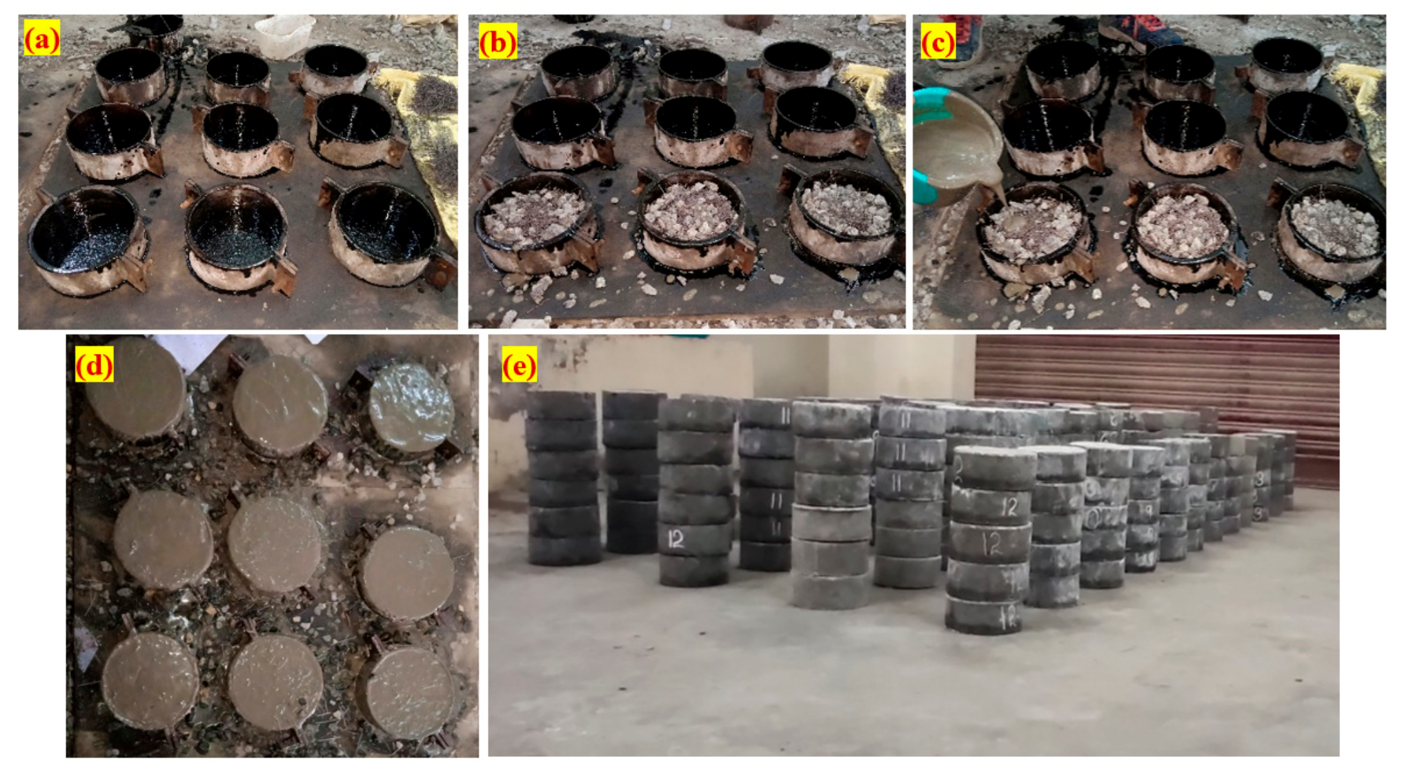
3.3. Specimen Preparation

The projectile impact performance of FPAFC was assessed by using 150 mm diameter and 64 mm thick cylindrical specimens, as indicated in Figure 4. The dimensions of the cylindrical specimens were taken from previously published literature [46] to ensure comparability and consistency. Additionally, cubical specimens of 100 mm were produced to determine the compressive strength. The manufacturing process for FPAFC comprised of the following step: an empty casting was first prepared and oil was applied to both sides before it was filled with gross aggregate and fibres, as illustrated in Figure 5a. Secondly, as illustrated in Figure 5b, the ground aggregate and fibres were pre-packed in the framework to produce the first layer of the natural skeleton. Third, cement grout was poured over the top surface layer of the specimen, as indicated in Figure 5c, and light compaction was applied to fill interstitial spaces in the skeletons so that honeycombing could not take place and the first layer was completed. The second and third layers were completed using the same method as described in Figure 5d for the first layer. Following casting, the specimens were allowed to undisturbed in the formwork 24 h before the demoulding procedure began, which took 28 days of immersion in water curing to complete. After demoulding, the appearance of the specimens became as shown in Figure 5e. The advancement of FPAFC via the idea of preplaced aggregate concrete allows for prepacking of coarse aggregates and fibres into the formwork and interlinking with each other. A strong skeleton formed due to the proper supervision given to the coarse aggregate and fibres during the packing process. The use of FPAFC in its fresh condition prevented the formation of variable thicknesses and the appearance of rippling layers.

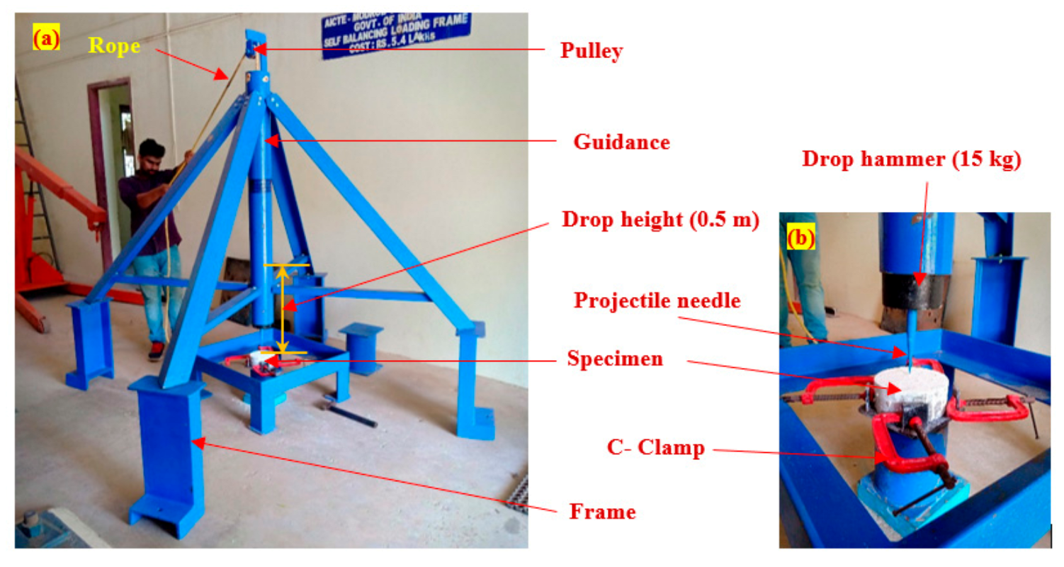
3.4. Projectile Impact Testing Device

The low-velocity projectile impact test was performed on concrete targets utilizing three different projectiles; compound bevel (CB), convex edge (CE) and hollow edge (HE) manufactured of non-deformable steel. The CB projectile had a 150 mm height and 20 mm diameter. The remaining two projectiles (CE and HE) had the same diameter of 20 mm and a height of 100 mm. From a height of 500 mm, a 15 kg hammer was dropped repeatedly at the middle of the top of the target surface and the velocity of the impact was 3.13 m/s. The self-constructed multiple projectile impact device utilized in this research is shown in Figure 6 was made in conformity with ASTM C803/C803M 18 [47]. The damage severity was quantified by the damaged area at top and bottom faces in addition to the depth of penetration. The depth of penetration was recorded manually for every two projectile impacts using a small needle and the average of four results was used for discussion. The damaged area was measured through image processing. The FPAFC cylindrical specimen was attached to a four-legged steel stool to demonstrate that the penetration is continuously occurring at the specimen center and prevents the target from laterally moving, as illustrated in Figure 6b. The appearance of three different projectiles used in this research is shown in Figure 7.

4. Results and Discussion

4.1. Compressive Strength

Three cubic specimens were cast from each combination and compressive strength measured in accordance with IS 516 [48]. Figure 8a shows the compressive strength of PAFC with single layer SF and PF. The compressive strength of the S-SF specimen was 59.6% improved compared to the PAC specimen. This improvement was attributable to the presence of SF, which created efficient bridges in the cracking zone, caused crack initiation and subsequent development to be delayed [49]. Conversely, the compressive strength enhancement of the S-PF specimen was just 18.6% compared to the PAC. This was because of the lower tensile strength and density of PF compared to SF [50]. The double-layer D-SF-PF and D-PF-SF specimens exhibited an increase in compressive strength of 26.1 and 23.0% compared to the PAC, as shown in Figure 8b. Findings indicated that the use of SF in single and double-layer concrete increased the compressive strength considerably. Single-layer concrete performance was also better than double-layer concrete. This may be explained by the uniform distribution in the composite of 3D-oriented fibres, which increased the load capacity under compression.
Three-layer FPAFCs with various fibre dosages showed a favourable improvement in compressive strength of 5.2 to 54.4%, as compared to PAC. This is shown in Figure 8c where the lowest compressive strength observed in this group was in the T-FG6 mix, which was 5.2% higher than PAC. This is because of the lower tensile strength of the 3.6% PF in the top and the bottom layers, while the intermediate layer was made of non-fibrous concrete. T-FG2, which composed of 2.8% SF in the top and lower layers and 1.6% in the intermediate layer, exhibited an improvement in compression strength of approximately 54.4% in comparison with PAC. All other FPAFC three-layer specimens exhibited an anticipated improvement in compressive strength. The greater dosage of mono and hybrid fibres added to the various schemes resulted in significant increases in compressive strength. The addition of fibres to concrete offered excellent bridging capacity. The fracture route was complex, requiring enormous force to extract the fibre action [1,50]. In general, the dosage of fibre used in fibrous conventional concrete has been limited to 2% because of workability-related problems, uniform fibre distribution and fibre clustering which create greater vacuum, leading to internal concrete defects, and reducing the compressive strength [22,51]. On the other hand, the PAC casting technique eliminated such problems by premixing and placing of coarse aggregates and fibres into the formwork prior to grout injection [52,53]. In a nutshell, for different concrete layers, the impact of SF on the improvement of compressive strength was considerably higher than in PF.

4.2. Failure Impact Number

The results of repeated impact tests are usually reported in terms of the number of impacts required to cause the specimen failure in addition to the distortion results represented by the deteriorated area and penetration depth. Figure 9, Figure 10, Figure 11 and Figure 12 visualize the influence of the investigated parameters, namely the projectile needle type, fibre type and fibre hybridization, on the obtained failure impact numbers. For better discussion, the concrete mix groups were collected in three main groups depending on the number of layers; single, double and triple layers.

4.2.1. Effect of Needle Type on the Failure Impact Number

The needle diameter, needle material, drop weight and drop height were kept constant, while the configuration of the needle tip was the investigated variable in Figure 9a–c. As defined in Section 3, three projectile needle types were used namely, compound bevel (CB), convex edge (CE) and hollow edge (HE) as visualized in Figure 7. It is obvious in Figure 9a that excluding the reference plain mixture (PAC), the CB needle type retained the lowest impact numbers among the three needle types for both the SF and PF single-layer mixtures (S-SF and S-PF). The retained impact numbers for CB, CE and HE needle types were 35, 48 and 50, respectively for S-SF specimens, while they were 16, 18 and 21, respectively for S-PF specimens. Lower failure impact number refers to lower impact resistance of the tested specimens. However, since identical specimens were tested under different needle configurations, the lower failure number reflects a faster deterioration regardless of the impact resistance, which is directly related to the ability of the projectile needle to cause a harder damage resulting in an accelerated failure. As a result, it can be concluded that the tapered end with longer sharpened tip of the CB needle, compared to CE and HE configurations, could cause more effective damage under repeated impacts resulting in an accelerated failure.
A similar trend of results was also recorded for the double-layer group, where for the D-SF-PF specimens, the retained failure numbers were 22, 32 and 36 for CB, CE and HE specimens, respectively as shown in Figure 9b, which reinforces the above obtained conclusion that using CB needle can accelerate the failure of the target specimens. The results of the seven triple-layer mixtures also support the results of the single and double-layer groups, where it is obvious in Figure 9c that regardless of the used fibre type and fibre distribution, the specimens tested under repeated impacts of CB projectile exhibited lower failure impact numbers compared to the other two projectile configurations. For instance, the retained failure impact numbers of the CB, CE and HE projectiles were 27, 36 and 38, respectively, for the T-FG1 mixture and 31, 36 and 34, respectively, for the T-FG7 mixture.
The comparison among the two rest types of needles is somewhat confusing. Considering the single-layer mixtures, it is shown that specimens tested with HE projectiles exhibited slightly lower failure impacts than those tested with CE projectiles, as shown in Figure 9a, where for S-SF and S-PF mixtures, the differences in the retained failure impact numbers between HE and CE were only two and three impacts, respectively. On the other hand, the retained numbers were equal (24 blows) for one of the double-layer mixtures (D-PF-SF) as shown in Figure 9b, while the triple-layer mixtures showed different behaviours. As shown in Figure 9c, the failure number of HE needle was higher that of CE for the mixtures T-FG2, T-FG3, T-FG5 and T-FG7, while they were approximately equal for both needle types for mixtures T-FG4 and T-FG6. On the other hand, the specimens of T-FG1 tested under HE needle retained lower impact number at failure than those tested under CE needle. Consequently, it can be concluded that both the CE and HE needle configurations resulted in comparable failure numbers, which reflects an equivalent impact effect of both configurations.

4.2.2. Effect of Fibre Type and Fibre Hybridization on the Failure Impact Number

Fibres, as short discrete reinforcing elements, have the potential to dramatically improve the mechanical properties of concrete that are controlled by any sort of tension failure. Fibres can control the widening and propagation of cracks by absorbing significant tensile stresses across the crack’s faces, connecting these faces and prevent or postpone the failure, which magnifies the strength and alters the structural behaviour from brittle to a more ductile one [54,55,56,57]. Previous studies showed that the use of steel fibres could increase the tensile strength, flexural strength, shear strength and impact resistance of plain elements and reinforced concrete members [58,59,60,61]. On the other hand, several types of synthetic fibres were introduced as successful matrix reinforcing elements to improve the materials and structural properties of concrete under different exposure conditions [62,63,64]. Polypropylene fibre (PF) was one of most used synthetic fibres due to its low cost and high performance in enhancing the ductility, toughness and impact capacity. Therefore, the sole and dual influences of SF and PF on concrete resistance to low-velocity repeated projectile impacts were investigated in this research.
Figure 10 shows the impact number results of specimens comprising 2.4% of only SF or only PF, thus, it explores the sole effect of each type of fibre on the impact resistance. It is obvious in the figure that specimens with polypropylene fibre (S-PF) retained noticeably higher impact numbers compared to the plain reference specimens (PAC). The resistance to projectile impacts in terms of impact number was increased by 33.3 to 162.2% under the three projectile needles compared to PAC plain specimens. On the other hand, the effect of SF in increasing the impact resistance was astonishing where the impact numbers increased by 191.7%, 500% and 525% for CB, HE and CE projectile needles, respectively. Hence, the use of 2.4% steel fibres magnified the absorbed impact energy by approximately three to six times that of PAC plain specimens. Comparing the results of the two fibrous mixtures (S-SF and S-PF) for each needle configuration, it is obvious that the retained impact numbers by S-SF specimens were 2.2 to 2.7 times those of S-PF ones, which shows the explicit superior impact performance of SF over PF. The better performance of SF is attributed to its superior physical properties (tensile strength and elastic modulus) compared to PF and its deformed configuration and hooked ends (Figure 3). The higher tensile strength of SF (1150 MPa) compared to PF (500 MPa) increased the ability of the fibre to withstand higher range of tensile stresses across the two ends of cracks, resulting in better bridging activity by postponing the breakage of fibres. On the other hand, the deformed shape of SF assured the case of perfect bond with the surrounding concrete media and prevented the brittle fibre pullout failure [65,66]. Consequently, SF could better magnify the crack bridging and helped the specimens to sustain higher number of impacts before failure.
Figure 11a shows the effect of fibre type on double-layer specimens, where in the first group (D-SF-PF), SF was incorporated in the top layer and PF was incorporated in the bottom layer, while the opposite was adopted for the second group of specimens (D-PF-SF). It was disclosed by the comparison of single layer specimens, that the contribution of SF was superior to that of PF by not less than two times. The setup of the repeated impact test requires that the specimen rests on a stiff steel plate, while the drop weight is released repeatedly on the top surface. Hence, the impact load is transferred initially as concentrated short-term compression stresses on the top surface. Hence, the top surface forms the first shield against the impact loads. Due to the surface hardness of concrete, the projectile needle rebounds after each blow, while partial damaging appears with the increase of number of impacts accompanied by the gradual dispersal of small concrete fragments and the fracture of the surface concrete. This action continuous with the repeated impacts and the depth of penetration increases, where the top concrete layer below the surface becomes the effective shield against the progressing of penetration and fragmenting [67]. Finally, the fragmented volume increases forming a semi-conical shape after the failure of the top layer and penetrates the bottom layer, which represent the last and weakest shield against the total failure. This sequence of fracture reveals that the greatest contribution to the overall resistance of layered specimens against projectile impacts comes from the resistance of the top layer.
This phenomenon explains the impact performance superiority of the D-SF-PF over the D-PF-SF, where the existence of SF fibre in the top layer resulted in impact numbers that are 1.1 to 1.5 times those of D-PF-SF with SF in the bottom layer. The impact results of the triple-layer groups (T-FG1 to T-FG-7) shown in Figure 11b support this conclusion, where the specimens with higher SF content in the top layer exhibited higher impact numbers than those with lower SF contents in the top layer, while the groups with PF in the top layer exhibited the lowest impact numbers among the seven groups. It is obvious Figure 11b that T-FG5 specimens with 3.6% SF at the top layer exhibited the ever-highest impact numbers among the seven triple-layer groups with impact numbers of 42 to 46 for the three projectile needles. On the other hand, the specimens with pure PF fibres at the top layer and the other layers (T-FG3 and T-FG6) exhibited the lowest impact numbers that ranged from 15 to 24 blows.

4.2.3. Effect of Number of Layers on the Failure Impact Number

Figure 12 compares specimens having 2.4% of SF and PF but in single, double and triple layers. For the triple-layer specimens, T-FG1 group which includes 2.4% of SF and PF (1.2% each) in all layers was adopted. On the other hand, to calculate the impact number of similar single-layer specimens, the average impact number of S-SF (with 2.4% SF) and S-PF (with 2.4% of PF) was used. Similarly, for the double-layer specimens, the average of D-SF-PF and D-PF-SF was used. Hence, the comparison between the three groups with the same fibre content and different numbers of layers (Figure 12) is symbolic to evaluate the number of concrete layers. Based on this methodology, it is obvious that adopting three layers increased the impact capacity compared to single and double-layer specimens. However, this result does not necessarily reflect the accurate behaviour, where the comparison between S-SF and the pure SF triple-layer specimens T-FG2 and T-FG5 reveals that the single layer specimens retained 48 and 50 blows for the HE and CE projectile cases, while T-FG2 and T-FG5 retained maximums of 46 and 44 blows. On the other hand, T-FG5 retained an impact number of 42 under CB projectile, which is higher than that of the single-layer specimens S-SF (35 blows). Hence, it can be said that a future work is required to explore this point by considering similar fibre quantities but in single, double and triple-layer forms.

4.3. Damage of Targets under Different Projectile

It is well recognized that many actions are driven by projectile impacts with low-velocity on composite targets [68]. In most cases, the high compression at the top surface and the tensile at the bottom surface results in cratering and scabbing produced on the top and bottom surfaces. With a continuous low-velocity impact, the needle hits the composite targets repeatedly. If the projectile’s velocity is lower, the projectile hits and ricochets off the composite target rather than causing significant local harm. The composite fragments are expelled from the top surface of the affected area under repeated blows with a low velocity and moderate mass. As the projectile impact is repeated, the projectile pierces the composite target further. It forms a cylindrical penetration hole with a diameter slightly more than the projectile diameter accompanied by a composite matrix ejected from the top surface, and the penetration depth increases at every impact. The bottom area of the composite target is breaking or damaging in line with scabbing under repeated impacts by the projectile needle on the target. The scabbing zone is usually considerably larger but not much deeper than the top of the crater. The penetration depth rises rapidly at the beginning of scabbing and the projectile emerges out of the bottom surface. The damage areas are created at the composite target’s top and bottom surfaces by the expulsion of fragments during the penetration of the composite target owing to its 15-kg projectile with a 3.13-m/s impact velocity. The images of the damaged areas at the top and bottom surfaces were taken using a high-resolution camera. All images were processed through image processing (Fiji image J software) to measure their damaged area. Table 2 demonstrates the results of measured damage areas under the three different projectiles.

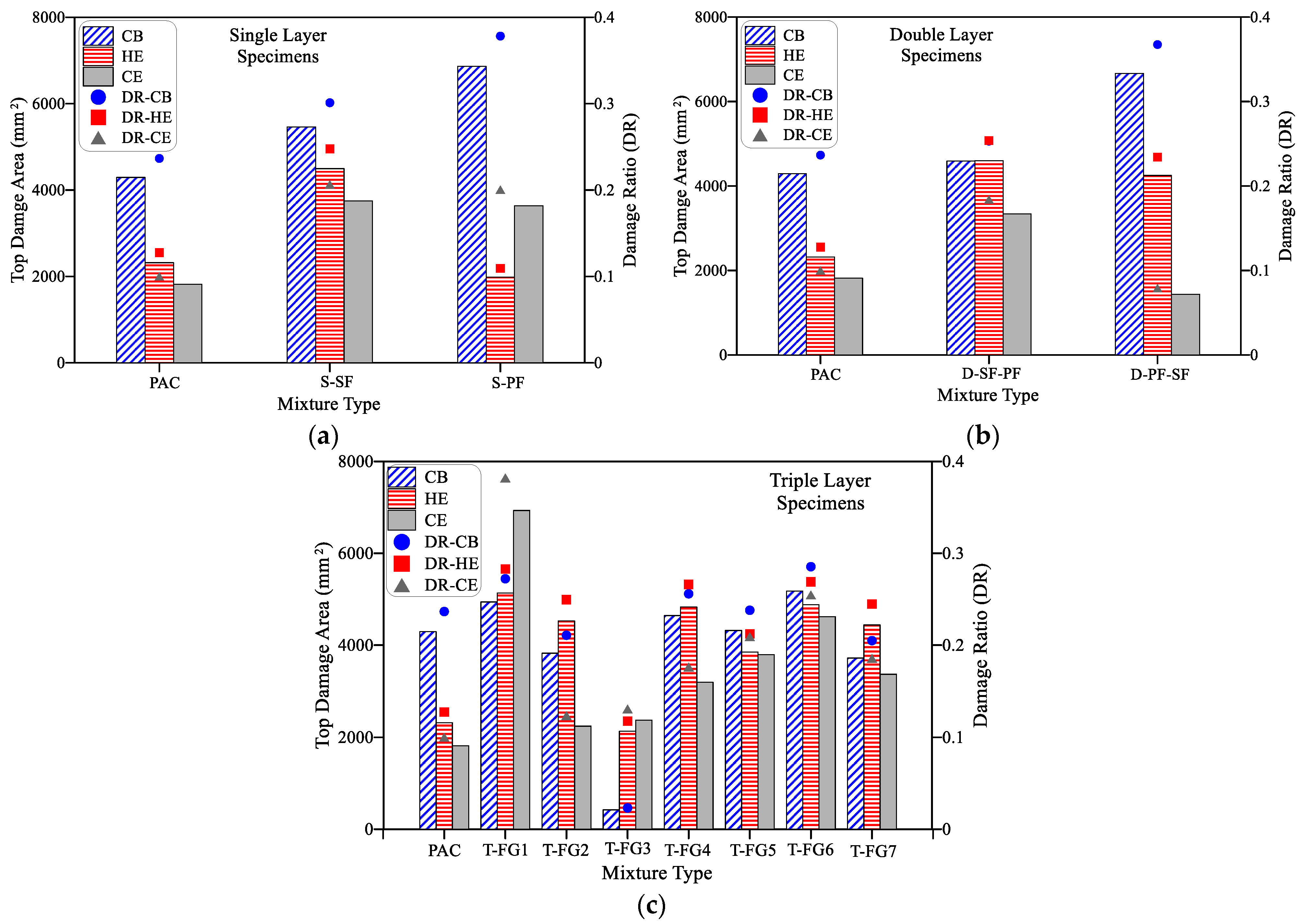
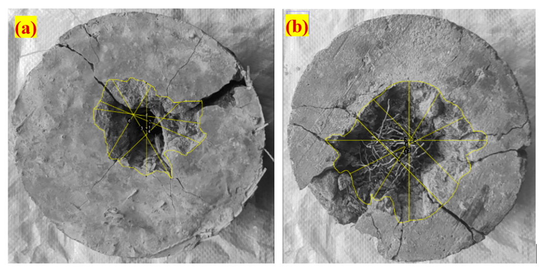
4.3.1. Top Damage Area

Repeated projectile impacts make the damaged region on the top surface of the target as the opening of the impingement area. The damaged area of the single, double and triple-layer composite targets against different projectile strikes is shown in Figure 13. The results showed that with the initial repeated projectile impacts, more damage area was recorded and reduced with the successive projectiles. The phenomenon is attributed to the exceptional resistance to crack and penetration of the FGPAC composite. This pattern is anticipated since the tiny crater was formed during the initial few repeated impacts on the front surface. In this occurrence, the pieces were expelled from the damaged region and after successive projectiles, a cylindrical penetration hole was created. Compared with other targets, significant damage occurred at the front surface with fewer impacts was found in PAC targets against CB, CE and HE projectile types, as shown in Figure 13. The recorded damage areas for the PAC target were 4293, 1816 and 2317 mm2, corresponding to CB, CE and HE projectile type impacts.
It can be prudently seen from Figure 13a that the highest damage areas (5463 and 6862 mm2) of S-SF and S-PF targets were recorded against the CB projectile with the corresponding failure impacts were 35 and 16, respectively. The damaged area was reduced with increased impact applied using the CE projectile. For example, the recorded damaged area for the S-SF and S-PF targets were 3749 and 3638 mm2, respectively, with the corresponding failure impacts were 48 and 18. Compared to the CE projectile, the damaged area was increased (4496 mm2) for the S-SF target and decreased (1984 mm2) for the S-PF targets with the corresponding impacts were 50 and 21, respectively. Comparing the damaging effect of the three projectiles, the CB exhibited a higher damage area with lesser impacts that can pierce the targets quickly than CE and HE projectiles. The damage trend for the targets subjected to CE and HE projectiles was nonuniform for the two targets. Compared to CE, the targets subjected to HE projectile exhibited an increasing trend for S-SF and decreasing trend for S-PF. The contribution of SF is way better than PF regarding the failure impact. This phenomenon is attributed to the presence of well-distributed SF reinforcing components that intersect the formed fractures and share substantial stresses that attempt to open the cracks because of the high tensile strength of the fibre [1]. This phenomenon delays the opening of the initial cracks leading to more excellent impact energy absorption [28].
The damage patterns of double-layer targets against the CB, CE, and HE projectile type impacts were similar to the single-layer targets. For example, for the D-SF-PF target, the recorded damaged areas were 4592, 3340 and 4602 mm2, with the corresponding failure impacts were 22, 32 and 36, respectively. Likewise, the recorded damage areas for the D-PF-SF target were 6667, 1437 and 4249 mm2, with the corresponding failure impacts of 20, 24 and 24, respectively. From Figure 13b, the damage effect of CB projectile is significantly more with lesser failure impacts than the CE and HE projectiles. The D-PF-SF targets comprised PF at the top layer exhibited higher damage area under CB projectile and lower under CE and HE projectiles. Compared to the D-SF-PF targets, the recorded damaged area for the D-PF-SF target was inconsistent due to the weak matrix finished at the top surface. Similar to single-layer concrete, the best contribution came from the SF compared to PF.
Triple-layer FPAFC targets exhibited top damaged area ranged from 422 to 5178 mm2 for CB projectile, 2244 to 6931 mm2 for CE projectile and 2135 to 5133 mm2 for HE projectile, as shown in Figure 13c. The best performance was recorded from this group was the T-FG5 target which displayed 42, 46 and 44 failure impacts corresponding to the projectile type of CB, CE and HE, respectively. This phenomenon is attributed to the top and middle composite targets contained a 3.6% dosage of SF, resulting in substantial resistance to impact. Besides, all FPAFC targets subjected to CB projectile displayed a higher damage area with lower failure impact blows. This phenomenon is due to the sharpness of a CB projectile tip with a diameter of 2.3 mm and gradually increased to 20 mm diameter at 98 mm height. The CB projectile pierced into the targets quickly, leading to the failure to happen faster than the targets subjected to CE and HE projectiles. The HE projectiles with 4.56 mm diameter at tip and gradually increased to 21 mm at 13.1 mm exhibited the second-highest impact failure for all FPAFC targets in this group. A slight delay in failure was recorded for the targets subjected to the CE type projectile due to its 1.7 mm tip diameter, where the projectile did not penetrate the targets rapidly. In a nutshell, the highest damage area was recorded for all targets subjected to CB projectile. Besides, the second-highest damage area was recorded for most of the FPAFC targets subjected to HE projectile followed by CE projectile. However, no clear damage area trend was noticed for the targets subjected to CE and HE projectile impacts.

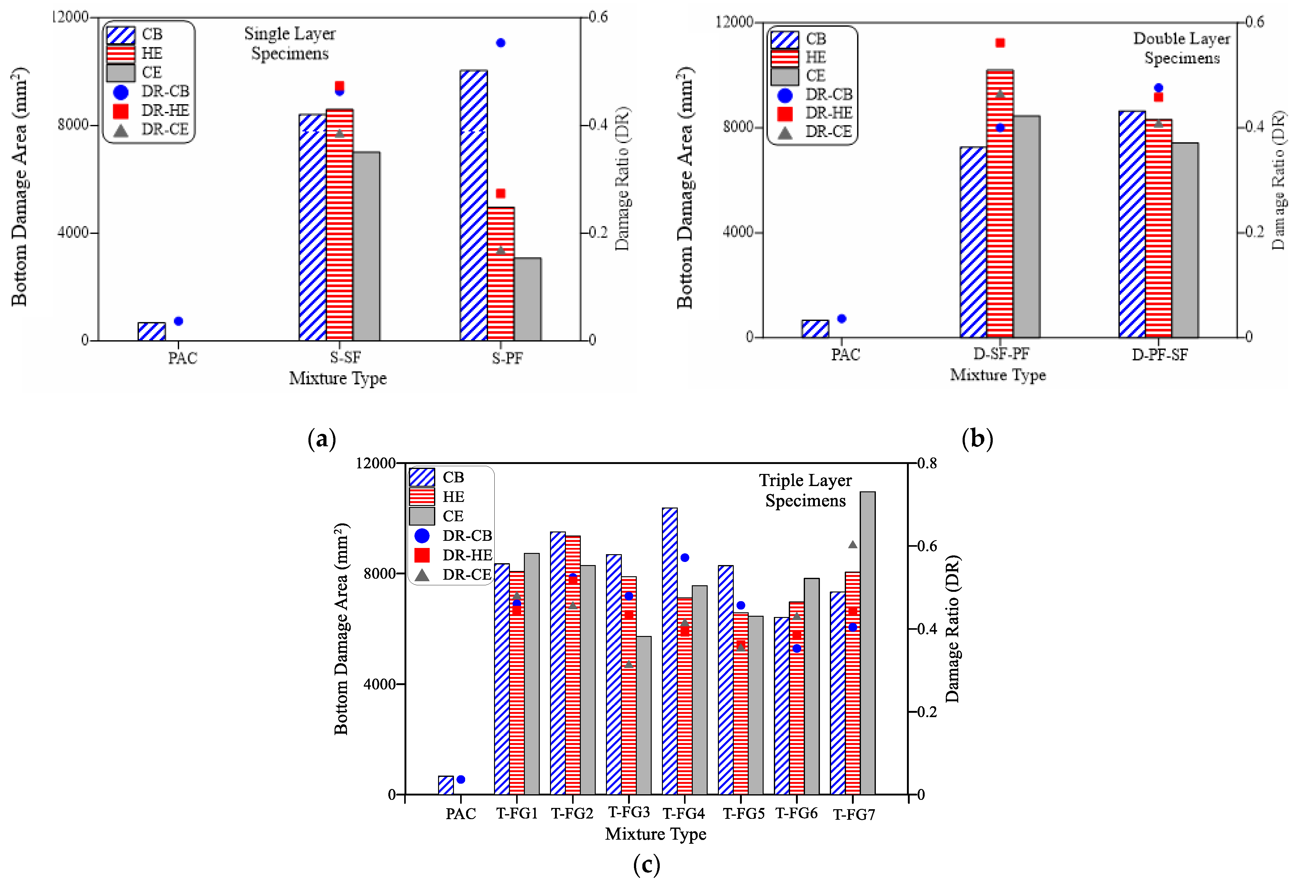
4.3.2. Bottom Damage Area

The damage area at the bottom surface is an essential criterion for defining the behaviour against penetration. The damaged area in the bottom surface is often much bigger than in the top since it is caused by a compressive wave produced by the projectile while a tensile wave develops on the bottom surface [62]. Cracking zone development may be mainly attributed to the growth of the elastic stress wave. It is generally considered that the produced longitudinal compression waves induce a sphere-shaped penetration into the FPAFC target owing to the projected impact load. When the wave hits the back surface, the tensile wave happened as a normal reflectivity [69]. A rapid reduction in compression and a rise in tensile waves could be achieved due to the superposition of the reflected tensile wave and compressive wave. The amplitude of the tensile wave exceeds the dynamic stress of the target, which results in the composite crushing and scabbing [46].
This parameter was evaluated using the diameter measured through image processing and the results were compared. The comparison revealed that PAC targets exhibited a damaged area of 668 mm2 when subjected to CB projectile, as shown in Figure 14a. In contrast, CE and HE projectiles pierced into the targets which were broken into two pieces showing no damaged area at the bottom surface. The absence of fibre bridging elements led the PAC targets to break into two pieces under few impacts irrespective of the projectile type. Single-layer S-SF targets containing SF subjected to CB, CE and HE projectiles exhibited a bottom damage area of 8409, 7005, 8591 mm2, with failure impacts were 35, 48 and 50, respectively. On the other hand, the S-PF targets with PF exhibited damaged areas of 10,041, 3072, 4964 mm2 for the projectile types CB, CE and HE, while their corresponding failure impact numbers were 16, 18 and 21, respectively. It is clear from the above results that targets subjected to CB projectile experienced more damage area followed by HE and CE projectiles. The projectile needle configuration played a vital role in changing the damaged area and failure impact numbers. By comparing the SF and PF-based targets, a significant enhancement in impact resistance was shown by the SF than PF fibres. The failure impact number and destroyed area were varied due to the fibre properties, where SF with high tensile strength and crimped shape at mid-portion and hooked ends provides a better anchorage effect. In contrast, PF had a low tensile strength with straight fibre configuration leading to less efficient resisting impacts compared to SF.
Double-layer targets D-SF-PF comprised SF at the top and PF at the bottom layers exhibited damaged areas of 7264, 8457 and 10,198 mm2 when subjected to CB, CE and HE projectiles, as shown in Figure 14b. The corresponding failure impact numbers for this target were 22, 32 and 36. Likewise, D-PF-SF comprised PF at the top and SF at the bottom layer exhibited damaged area of 8643, 7427 and 8319 mm2 with the corresponding failure impact numbers were 20, 24 and 24, respectively. It can be seen from the results that the more damaged area was observed in the D-SF-PF targets due to the presence of PF with a low tensile strength at scabbing region. At the same time, a lesser damaged area was noticed in D-PF-SF targets due to the presence of SF in the scabbing region. Fibre presence across the fracture leads to an adequate enhancement in stress transmission, absorbing greater energies of impact and limiting crack enlargement [1]. Higher failure impact numbers are required to break the connection between the surrounding concrete medium and fibres. The breakdown of a bond produces the fibre pull-out with a target failure [67].
Triple-layer targets showed a favorable implication in reducing the damaged area at the bottom surface of the targets, as shown in Figure 14c. FPAFC targets subjected to CB projectile exhibited damaged areas ranged from 6408 to 10,373 mm2 with lesser failure impact numbers than CE and HE projectile impacts. This phenomenon is due to the projectile needle configuration and fibre scheme provided at the top and bottom layers. The damaged areas of targets ranged from 6452 to 10,963 mm2, 6574 to 9360 mm2 for the projectiles CE and HE, respectively. The failure impact numbers for the targets against CB, CE and HE projectiles ranged from 16 to 42, 20 to 46 and 19 to 44, respectively. It is clear from the above results that the shape of the projectile needle influences the damaged area and impact failure number. The best performance from this group was exhibited by T-FG5 targets irrespective of the projectile type. The presence of a high dosage of fibres at the bottom layer resulted in improved bonding with the adjacent cement matrix and increased efficiency of fibre bridging action, allowing the material to absorb more impact energies and inhibiting fibre pull-out from the cement matrix. This action delayed fracture starting while simultaneously increased the cracking resistance, resulting in higher failure impact numbers [1].

4.3.3. Damage Ratio

Damage ratio is defined by the ratio of the damaged area measured after impact from the top/bottom surfaces to the actual area before the impact [67]. Figure 13 and Figure 14 show that the recorded damage ratio of the bottom surface was higher in all targets than that of the top surface. The recorded damage ratios of the PAC targets for the top surface ranged from 0.10 to 0.24, while the bottom damage ratio was 0.04 against CB projectile impact. Since no damaged area was observed in PAC targets under CE and HE projectiles, the damage ratio for the targets against these projectiles is none. On the other hand, fibrous composite targets exhibited a top damage ratio ranged from 0.11 to 0.38 and a bottom damage ratio ranged from 0.17 to 0.60. However, more failure impact numbers were recorded for these targets compared to PAC targets, as discussed in the previous sections.

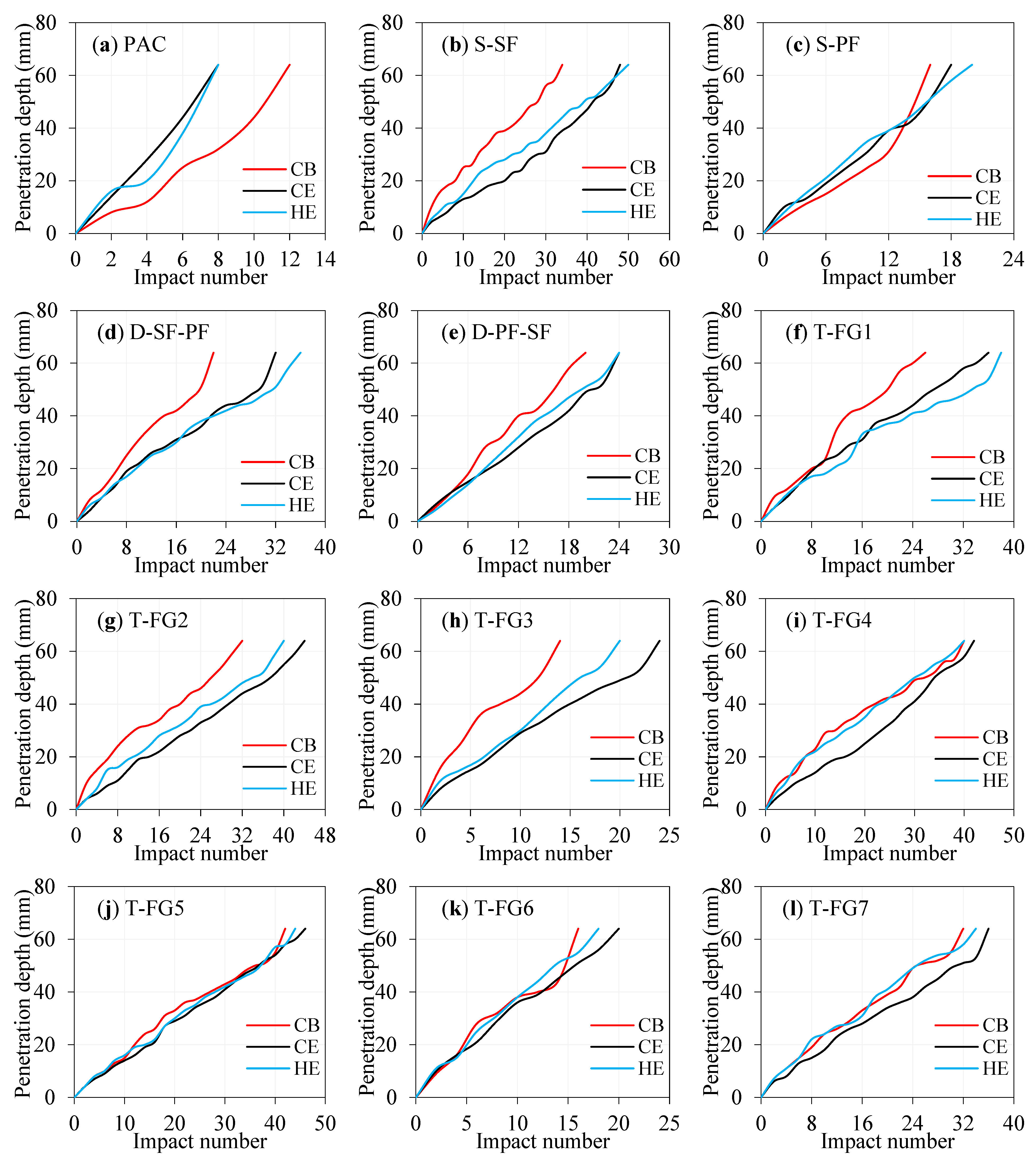
4.3.4. Penetration Depth

The penetration depth is described as the distance travelled by the projectile within the composite target normal to the contact surface [67]. During the failure impact, the projectile is considered to pierce the targets completely. Figure 15a–l illustrates the tendency to an increasing penetration depth as the repeated projectiles strike the target. All the curves in the figures showed a linear trend which indicates that the penetration happens gradually under the effect of the projectile impact loading. The penetration depths of PAC targets subjected to CB, CE and HE projectiles have a slight difference in failure impact numbers, as shown in Figure 15a. The single, double and triple-layer targets showed higher resistance to penetration compared to PAC targets. There was no evidence of damage to the bottom face in the fibrous targets during the initial impacts, including scabbing. The penetration depth of the target increased by the repetitive low-velocity projectile impact was limited to specific regions and that the specimen stayed intact as a single piece following the hits. Therefore, it is essential to add sufficient amounts of fibres into the composite targets to avoid catastrophic property losses and life casualties caused by the ejection of fragments from targets during the impacts. It can be observed from Figure 15 that the penetration occurred rapidly with repeated CB projectiles than CE and HE, regarding the failure impact numbers. This phenomenon is due to the sharpness of the CB needle contact point with targets leading to piercing the targets without deforming the projectile needle rapidly. Excellent resistance to penetration of targets was achieved when subjected to CE and HE projectiles compared to CB. The resistance to penetration of targets against CE and HE was more or less the same, with a slight difference in impact failure number. This phenomenon is due to the less sharpness of the projectile tip and needle shape, affecting the penetration depth and failure impacts, as discussed in the earlier sections. All projectiles were not deformed during the repeated impacts. However, the scratches on the body’s surface became deeper with greater body mass wear due to the projectile penetration into targets. The findings indicated that the excellent resistance to penetration was observed in the single and double-layer targets comprised SF. Fibre addition into composite targets has been shown in previous studies as the most effective method for increasing hardness, energy absorption, tensile strength and shear strength [67].

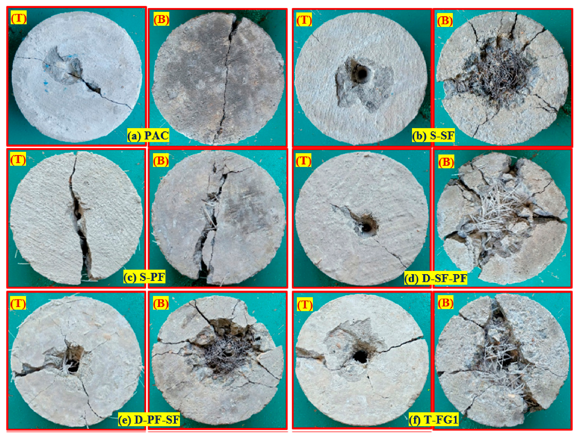
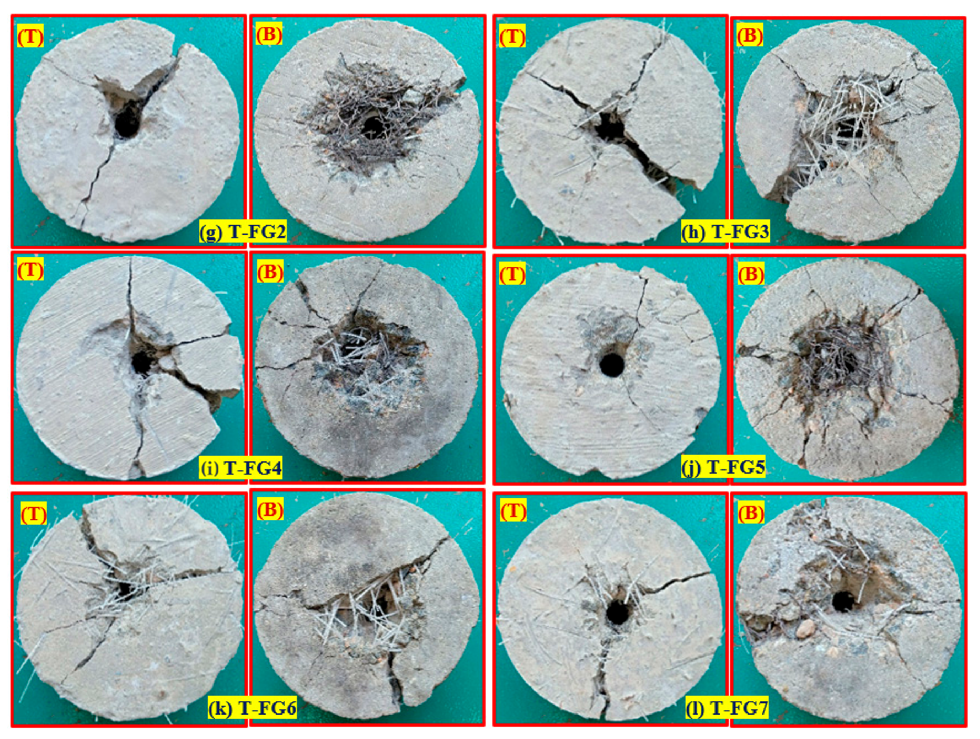
4.3.5. Failure Pattern

Figure 16a–l depicts the observed failure patterns of the composite targets at the top and bottom surfaces when subjected to impacts from the HE projectile. Similar failure patterns were observed in the targets subjected to CB and CE projectiles. Three different types of failure patterns were observed in the targets and were categorized. Firstly and foremost, a penetration in the top surface, followed by a reduction in the damaged area, happened at an early stage of impacts [46]. At this moment, the projectile penetrated the target and became stuck within it, rather than ricocheting back. Observations of the pierced hole combined with scabbing (top damaged region) were frequent on the top surface of the targets. It was noticed that cracks at the microscopic level propagated from the pierced hole, as shown in Figure 16. Secondly, with the increase of the number of repeated projectiles, a rise in penetration depth was noted, followed by an increase in the damaged area at the top surface. At this stage, the penetration failure mode was seen on the top surface, but there was no real damage on the rear surface. In the third instance, the failure pattern on the bottom surface manifested itself in a specific manner, puncturing holes and spalling with a larger diameter. Even though the broad back spalling with flying debris was seen as depicted in Figure 16, the fibrous targets had not yet been fully fragmented into numerous pieces at this time. In this case, fibre bridging activity maintained the fragmented parts connected to the target specimen [67].
The evolution of fracture resistance is the most important technical element of resisting the impact load caused by a projectile. The observed cracking zone may be mainly attributed to the development of elastic waves. It is established that longitudinal waves are produced due to the impact stresses induced by the projectile proliferate in spherical form into the FPAFC target. Upon reaching the bottom surface of the wave, the normal incidence reflectivity of the tensile wave occurs. The compressive wave from the top surface and tensile wave reflected from the rear surface cause a rapid reduction in the compressive wave and a rapid increase in the tensile wave. As a result, the amplitude of the tensile wave increases to a more remarkable level than the dynamic tensile strength at any location of the target. As a result, scabbing and cracking were observed. Figure 17 shows the measurement of the damaged area at the top and bottom surfaces using image processing. All images were processed using the Fiji Image J software to measure their damage area at the top and bottom surfaces. As illustrated in Figure 18, the projectile impacts caused four major damage zones to develop in each FPAFC target: crater, penetration, crushed aggregate and broad cracking. These damages were occurred in each FPAFC target due to projectile impacts. Scabbing has also been observed wherein multiple projectiles separated a composite mass from the FPAFC bottom surface due to the impact stresses. The shape and size of the damaged area varied based on the nose of the projectiles and the FPAFC strength. In practical terms, the suggested FPAFC may be regarded as a suitable option for constructing a defence structure with extraordinary impact resistance capabilities.

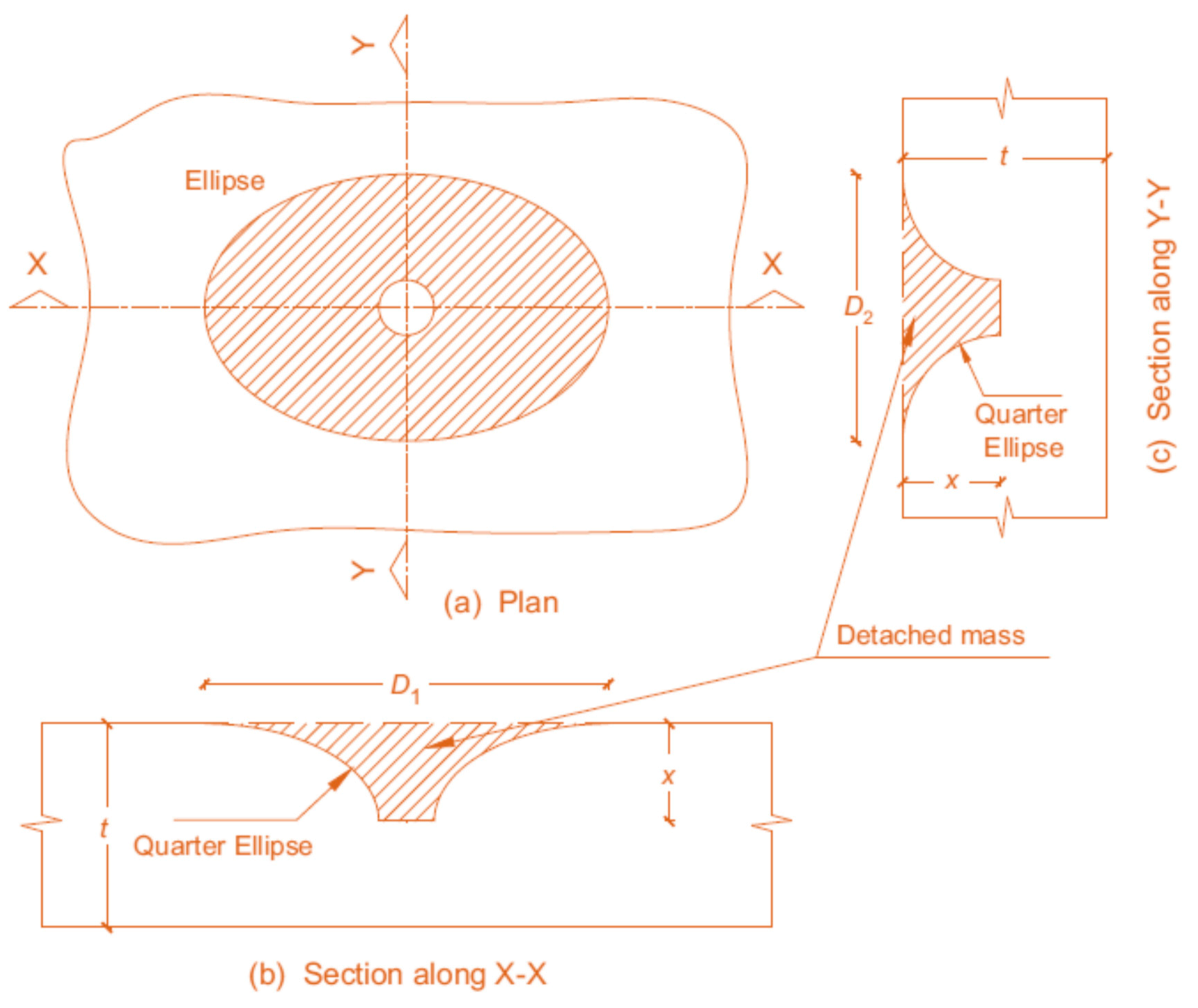
5. Assessment of Mass Expulsion from Top Surface

The research also predicted the expulsion of composite mass from the top surface of the targets. The expelled mass was measured experimentally using the sand filling method. The penetration hole was sealed at a particular depth (end of quarter circle ellipse shown in Figure 19) and the sand was filled up to the specimen’s top surface and leveled. After that, the weight of filled sand was measured to find the volume of ejected mass using the sand’s density. The mass expelled from the specimen was calculated using specimen’s density and volume of ejected mass. As illustrated in Figure 19 and Figure 20, the mass expulsion from the top surface was calculated using crater and tunnel by idealizing the damage. The crater’s shape at the top surface was presumed to be elliptical and the crater shape was deemed circular at the penetration depth. The latter dimension was assumed to be equal to the body diameter of the projectile. The change in the shape of the crater section from the top to the penetration depth was considered an ellipse (Figure 19 and Figure 20). The elliptic shape of the top face crater was substituted with an equal circle for simplicity. The expelled weight of composite was then calculated by:
M = γ v = 0 x u = r u 2 π   u   d u d y + π 4 d 2 x
The first term integration and rearranging give the equation as follows:
M = π 4 γ   x d 2 v = 0 x 4 u 2 d 2 d v
The variable u may be calculated by assuming an elliptical quadrant of the crater line (around the tunnel). Therefore, the crater line may be represented as in Equation (3):
u R 2 R r 2 + v x 2 x 2 = 1
The above Equation (3) yields,
u = D e 2 + D e d 2 x 2 x v v 2
Substituting the equation of ‘u’ into Equation (2) and integrating the result gives the following expression:
M = γ π x 24 4 λ d 2 + D e 2 5 D e 4 d 3 π D e d
As shown in Figure 20, R, De/2 = equivalent crater radius and diameter; u and v = variables. r, D = tunnel radius and diameter (assumed equal to the projectile body radius and diameter); x = penetration depth, and γ = composite target density. An additional parameter, λ has been added into the above equation, whose value is zero when the target is perforated; otherwise, its value is unity. When the parameter λ is set to zero, the tunnel mass is added to the mass expelled from the top surface, resulting in the final mass. In addition, it is essential to note that the expelled mass calculation from the top surface described above is valid even when there are no rebar on the top surface.
Figure 21 illustrates a comparison of the experimental and predicted mass expelled from the top surface since fewer data points fall outside of the line. Targets subjected to CB projectiles with the minimum and maximum error range of 2.08% and 9.24%, respectively. Minimum and maximum errors of 1.99% and 10.79% were observed in the targets subjected to CE projectile. These errors were 2.9% and 9.6% in the case of targets subjected to HE projectile. The regression coefficient (R2) value from the comparison of experimental and predicted values was hitting 0.950 in all cases and the percentage error between them was less than 11%. This may be ascribed to ambiguities in the idealization, minor mass participation, and measurement mistakes introduced by humans during the measurement of expelled masses. This model may be regarded as very satisfactory since the predicted expelled masses from the top surface are in excellent agreement with the experimental expelled masses, which indicates that the model is quite precise.

6. Conclusions

The following points summarize the most important concluding remarks obtained from this research,
(1)
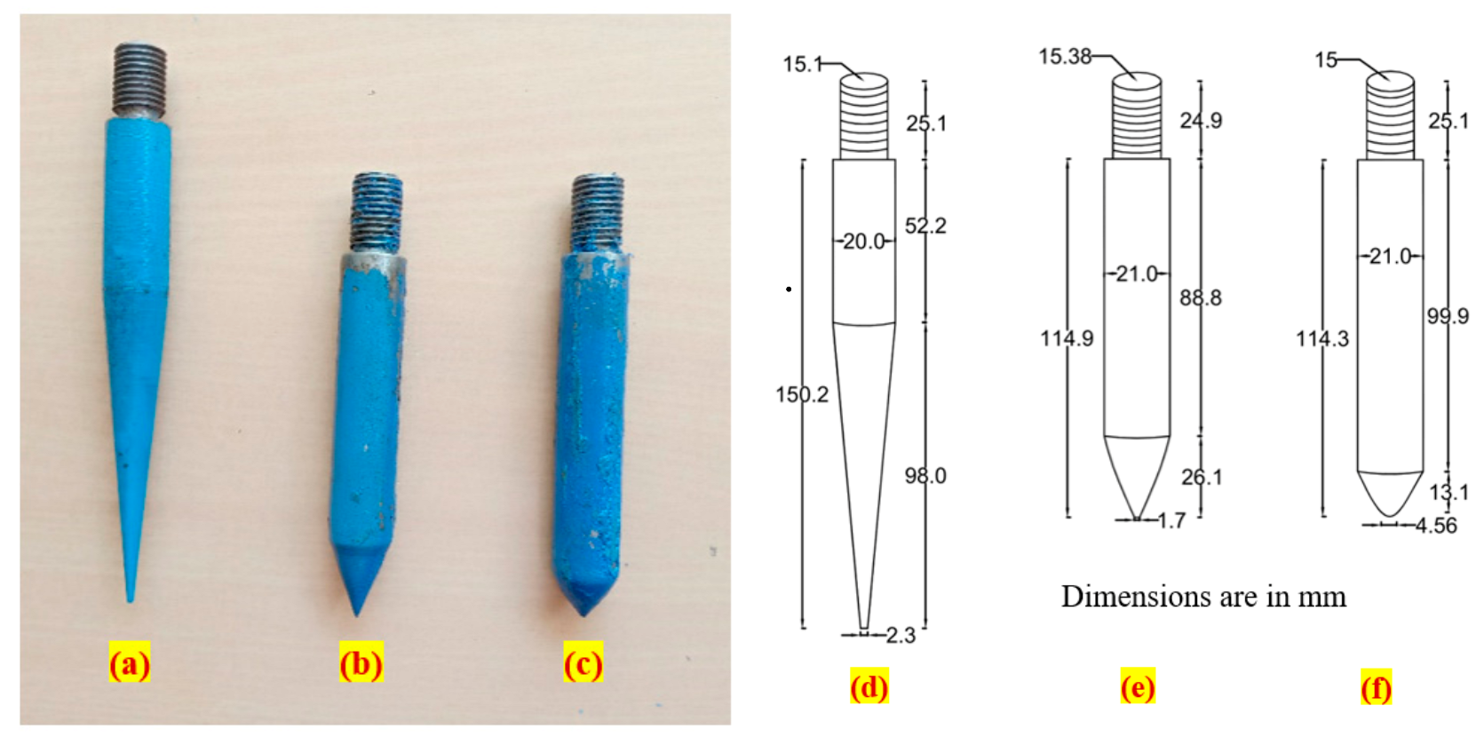
For fibrous specimens, using the compound bevel (CB) projectile needle resulted in the lowest impact numbers for all single, double and triple-layer specimens compared to convex edge (CE) and hollow edge (HE) projectiles regardless of the fibre type, content and distribution. For instance, for the single-layer specimens with 2.4% SF, the recorded impact numbers were 35, 48 and 50 under CB, CE and HE projectile needles, respectively. Thus, the use of CB projectile needle having tapered end with longer sharpened tip resulted in a quicker deterioration and hence accelerated the impact failure compared to CE and HE ones.
(2)
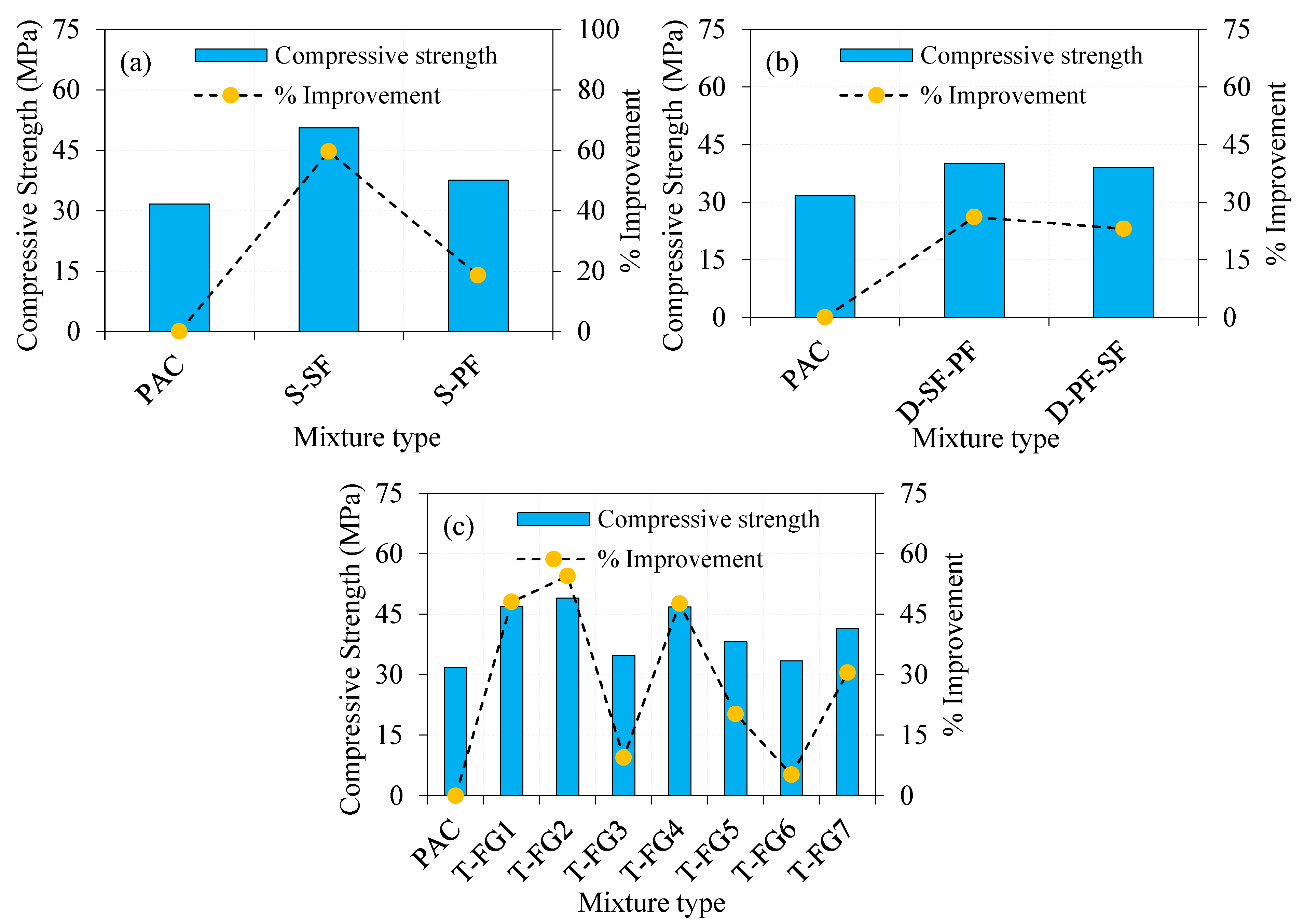
For the single-layer specimens, the steel fibre (SF) reinforced specimens exhibited higher percentage improvements in the retained impact number by 2.2 to 2.7 times compared to the polypropylene fibre (PF) ones, while their recorded impact numbers were approximately three to six times those of reference plain specimens. This behaviour is attributed to the higher tensile strength of SF compared to PF and its deformed shape that allowed the fibres to absorb higher tensile stresses across the cracks and prevented the brittle anchorage bond failure. For the same reason, the double and triple-layer specimens with higher content of SF in the top layer exhibited higher resistance under the repeated projectile impacts compared to the other fibre distributions. This leads to the conclusion that the top layer is the first shield against the concentrated surface impacts; hence, the better reinforcement of this layer using SF would result in an optimum impact performance.
(3)
The projectile needle shape influences the damaged area at the top and bottom surfaces. All CB projectile targets had the greatest damage area. Moreover, most FPAFC objects tested under HE projectiles had the second-highest damaged area, followed by CE projectiles. Targets tested under CE and HE projectiles showed no apparent pattern in the damaged area. Triple-layer targets showed a favourable implication in reducing the damaged area with increased failure impact than double-layer targets. A small damage area was observed in PAC targets irrespective of needle type, which tended to break the targets into two pieces. However, fibrous composite targets experienced punctured holes rather than breaking into two pieces.
(4)
Repeated projectile impacts increased the penetration depth in all targets. Targets were more resistant to CE and HE projectile penetrations than CB. Target resistance to the penetration of CE and HE projectiles was similar, with a slight variation in impact failure number. Repeated hits did not bend any projectiles; instead, more significant scratches on the body surface indicated higher body mass degradation. SF targets with single, double, and triple layers showed outstanding resistance to penetration.
(5)
Three different types of failure patterns were noticed in the fibrous targets irrespective of projectile needle; penetration in the top surface, followed by a reduction in the damaged area during the initial impacts, an increase in penetration depth caused by repeated projectiles, a specific manifestation of the failure pattern on the bottom surface which punctured holes and spread with a wider diameter. At the same time, this failure pattern was not noticed in the reference targets (PAC).
(6)
For predicting the mass expelled from the top surface of the targets, a single formulation has been used. The maximum percentage difference between the experimental and predicted values was 9.24 for CB, 10.79 for CE, and 9.6 for HE projectiles, hitting the coefficient of determination greater than 0.950. Thus, the findings of the experiments and analytical model are reasonably satisfactory.

Author Contributions

Conceptualization, N.P. and G.M.; methodology, N.P. and G.M.; software, N.P. and G.M.; validation, N.P. and G.M.; formal analysis, N.P. and G.M.; investigation, N.P. and G.M.; resources, N.P. and G.M.; data curation, N.P. and G.M.; writing—original draft preparation, N.P., G.M. and N.V. writing—review and editing, S.R.A., N.V., R.F., M.A. visualization, G.M.; supervision, G.M.; project administration, G.M.; funding acquisition, N.V. All authors have read and agreed to the published version of the manuscript.

Funding

The research is partially funded by the Ministry of Science and Higher Education of the Russian Federation under the strategic academic leadership program ‘Priority 2030’ (Agreement 075-15-2021-1333 dated 30 September 2021).

Institutional Review Board Statement

Not applicable.

Informed Consent Statement

Not applicable.

Data Availability Statement

Not applicable.

Acknowledgments

The authors gratefully acknowledge the School of Civil Engineering, SASTRA Deemed University for the support.

Conflicts of Interest

The authors declare no conflict of interest.

References

  1. Prasad, N.; Murali, G. Research on flexure and impact performance of functionally-graded two-stage fibrous concrete beams of different sizes. Constr. Build. Mater. 2021, 288, 123138. [Google Scholar] [CrossRef]
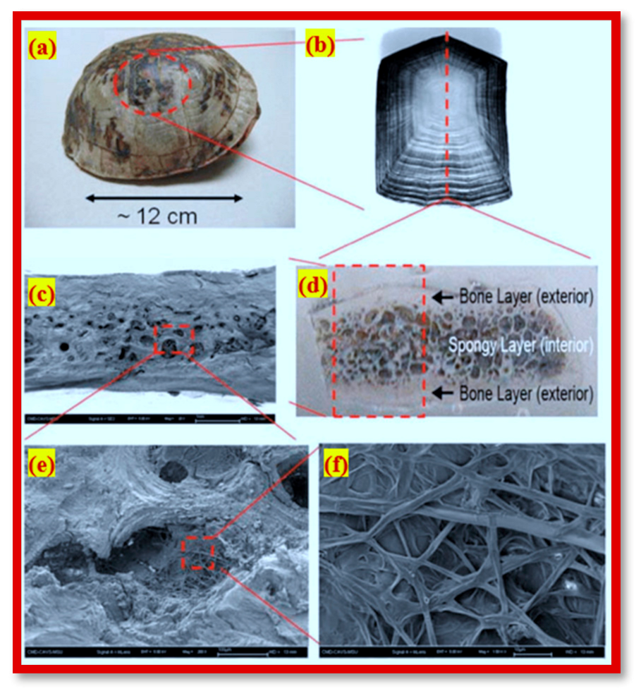
  2. Rhee, H.; Horstemeyer, M.F.; Hwang, Y.; Lim, H.; El Kadiri, H.; Trima, W. A study on the structure and mechanical behavior of the Terrapene carolina carapace: A pathway to design bio-inspired synthetic composites. Mater. Sci. Eng. 2009, 29, 2333–2339. [Google Scholar] [CrossRef]
  3. Meyers, M.A.; Chen, P.-Y.; Lin, A.Y.-M.; Seki, Y. Biological materials: Structure and mechanical properties. Prog. Mater. Sci. 2008, 53, 1–206. [Google Scholar] [CrossRef] [Green Version]
  4. Sachs, C.; Fabritius, H.-O.; Raabe, D. Experimental investigation of the elastic–plastic deformation of mineralized lobster cuticle by digital image correlation. J. Struct. Biol. 2006, 155, 409–425. [Google Scholar] [CrossRef]
  5. Seki, Y.; Kad, B.; Benson, D.; Meyers, M.A. The toucan beak: Structure and mechanical response. Mater. Sci. Eng. C 2006, 26, 1412–1420. [Google Scholar] [CrossRef]
  6. Zhang, X.; Cai, Z.-B.; Li, W.; Zhu, M.-H. Understanding hydration effects on mechanical and impacting properties of turtle shell. J. Mech. Behav. Biomed. Mater. 2018, 78, 116–123. [Google Scholar] [CrossRef]
  7. Ong, C.W.R.; Zhang, M.-H.; Du, H.; Pang, S.D. Functionally layered cement composites against projectile impact. Int. J. Impact Eng. 2019, 133, 103338. [Google Scholar] [CrossRef]
  8. Wang, L.; Zeng, X.; Yang, H.; Lv, X.; Guo, F.; Shi, Y.; Hanif, A. Investigation and Application of Fractal Theory in Cement-Based Materials: A Review. Fractal Fract. 2021, 5, 247. [Google Scholar] [CrossRef]
  9. Wang, L.; Li, G.; Li, X.; Guo, F.; Tang, S.; Lu, X.; Hanif, A. Influence of reactivity and dosage of MgO expansive agent on shrinkage and crack resistance of face slab concrete. Cem. Concr. Compos. 2021, 104333. [Google Scholar] [CrossRef]
  10. Wang, L.; Guo, F.X.; Yang, H.M.; Wang, Y.; Tang, S.W. Comparison of FLY ASH, PVA Fiber, MgO and Shrinkage-reducing Admixture on the Frost Resistance of Face Slab Concrete via Pore Structural and Fractal Analysis. Fractals 2021, 29, 2140002. [Google Scholar] [CrossRef]
  11. Maho, B.; Sukontasukkul, P.; Jamnam, S.; Yamaguchi, E.; Fujikake, K.; Banthia, N. Effect of rubber insertion on impact behavior of multilayer steel fiber reinforced concrete bulletproof panel. Constr. Build. Mater. 2019, 216, 476–484. [Google Scholar] [CrossRef]
  12. Nemkumar, B.; Mindess, S. Impact Resistance of Steel Fiber Reinforced Concrete. ACI Mater. J. 1996, 93, 472–479. [Google Scholar] [CrossRef]
  13. Banthia, N.; Nandakumar, N. Crack growth resistance of hybrid fiber reinforced cement composites. Cem. Concr. Compos. 2003, 25, 3–9. [Google Scholar] [CrossRef]
  14. Amran, M.; Fediuk, R.; Abdelgader, H.S.; Murali, G.; Ozbakkaloglu, T.; Lee, Y.H. Fiber-reinforced alkali-activated concrete: A review. J. Build. Eng. 2021, 45, 103638. [Google Scholar] [CrossRef]
  15. Lesovik, V.; Fediuk, R.; Amran, M.; Alaskhanov, A.; Volodchenko, A.; Murali, G.; Uvarov, V.; Elistratkin, M. 3D-Printed Mortars with Combined Steel and Polypropylene Fibers. Fibers 2021, 9, 79. [Google Scholar] [CrossRef]
  16. Rios, J.D.; Leiva, C.; Ariza, M.P.; Seitl, S.; Cifuentes, H. Analysis of the tensile fracture properties of ultra-high-strength fiber-reinforced concrete with different types of steel fibers by X-ray tomography. Mater. Des. 2019, 165, 107582. [Google Scholar] [CrossRef]
  17. Lin, X. Numerical simulation of blast responses of ultra-high performance fibre reinforced concrete panels with strain-rate effect. Constr. Build. Mater. 2018, 176, 371–382. [Google Scholar] [CrossRef]
  18. Schneider, K.; Michel, A.; Liebscher, M.; Terreri, L.; Hempel, S.; Mechtcherine, V. Mineral-impregnated carbon fibre reinforcement for high temperature resistance of thin-walled concrete structures. Cem. Concr. Compos. 2019, 97, 68–77. [Google Scholar] [CrossRef]
  19. Goldfeld, Y.; Rabinovitch, O.; Fishbain, B.; Quadflieg, T.; Gries, T. Sensory carbon fiber based textile-reinforced concrete for smart structures. J. Intell. Mater. Syst. Struct. 2015, 27, 469–489. [Google Scholar] [CrossRef]
  20. Chen, M.; Gao, P.; Geng, F.; Zhang, L.; Liu, H. Mechanical and smart properties of carbon fiber and graphite conductive concrete for internal damage monitoring of structure. Constr. Build. Mater. 2017, 142, 320–327. [Google Scholar] [CrossRef]
  21. Wu, Z.; Shi, C.; He, W.; Wang, D. Uniaxial Compression Behavior of Ultra-High Performance Concrete with Hybrid Steel Fiber. J. Mater. Civ. Eng. 2016, 28, 6016017. [Google Scholar] [CrossRef]
  22. Nehdi, M.L.; Najjar, M.F.; Soliman, A.M.; Azabi, T.M. Novel steel fibre-reinforced preplaced aggregate concrete with superior mechanical performance. Cem. Concr. Compos. 2017, 82, 242–251. [Google Scholar] [CrossRef]
  23. Wang, N.; Mindess, S.; Ko, K. Fibre reinforced concrete beams under impact loading. Cem. Concr. Res. 1996, 26, 363–376. [Google Scholar] [CrossRef]
  24. Isla, F.; Ruano, G.; Luccioni, B. Analysis of steel fibers pull-out. Experimental study. Constr. Build. Mater. 2015, 100, 183–193. [Google Scholar] [CrossRef]
  25. Yu, R.; Spiesz, P.; Brouwers, H. Energy absorption capacity of a sustainable Ultra-High Performance Fibre Reinforced Concrete (UHPFRC) in quasi-static mode and under high velocity projectile impact. Cem. Concr. Compos. 2016, 68, 109–122. [Google Scholar] [CrossRef]
  26. Quek, S.; Lin, V.; Maalej, M. Development of functionally-graded cementitious panel against high-velocity small projectile impact. Int. J. Impact Eng. 2010, 37, 928–941. [Google Scholar] [CrossRef]
  27. Moghadam, A.S.; Omidinasab, F.; Dalvand, A. Experimental investigation of (FRSC) cementitious composite functionally graded slabs under projectile and drop weight impacts. Constr. Build. Mater. 2020, 237, 117522. [Google Scholar] [CrossRef]
  28. Mastali, M.; Naghibdehi, M.G.; Naghipour, M.; Rabiee, S. Experimental assessment of functionally graded reinforced concrete (FGRC) slabs under drop weight and projectile impacts. Constr. Build. Mater. 2015, 95, 296–311. [Google Scholar] [CrossRef]
  29. Lai, J.; Yang, H.; Wang, H.; Zheng, X.; Wang, Q. Penetration experiments and simulation of three-layer functionally graded cementitious composite subjected to multiple projectile impacts. Constr. Build. Mater. 2019, 196, 499–511. [Google Scholar] [CrossRef]
  30. Canfield, J.A.; Clator, I.G. Development of a Scaling Law and Techniques to Investigate Penetration in Concrete; United States Naval Weapons Laboratory: Washington, DC, USA, 1966. [Google Scholar]
  31. Frew, D.; Hanchak, S.; Green, M.; Forrestal, M. Penetration of concrete targets with ogive-nose steel rods. Int. J. Impact Eng. 1998, 21, 489–497. [Google Scholar] [CrossRef]
  32. Wu, H.; Qian, F.; Huang, F.; Wang, Y. Projectile Nose Mass Abrasion of High-Speed Penetration into Concrete. Adv. Mech. Eng. 2012, 4, 296503. [Google Scholar] [CrossRef] [Green Version]
  33. Mu, Z.; Zhang, W. An investigation on mass loss of ogival projectiles penetrating concrete targets. Int. J. Impact Eng. 2011, 38, 770–778. [Google Scholar] [CrossRef]
  34. Guo, L.; He, Y.; Zhang, X.; Pang, C.; Qiao, L.; Guan, Z. Study mass loss at microscopic scale for a projectile penetration into concrete. Int. J. Impact Eng. 2014, 72, 17–25. [Google Scholar] [CrossRef]
  35. Nia, A.A.; Zolfaghari, M.; Khodarahmi, H.; Nili, M.; Gorbankhani, A.H. High Velocity Penetration of Concrete Targets with Eroding Long- Rod Projectiles; An Experiment and Analysis. Int. J. Prot. Struct. 2014, 5, 47–63. [Google Scholar] [CrossRef]
  36. Gold, V.M.; Vradis, G.C.; Pearson, J.C. Concrete Penetration by Eroding Projectiles: Experiments and Analysis. J. Eng. Mech. 1996, 122, 145–152. [Google Scholar] [CrossRef]
  37. Alrshoudi, F.; Mohammadhosseini, H.; Tahir, M.M.; Alyousef, R.; Alghamdi, H.; Alharbi, Y.; Alsaif, A. Drying shrinkage and creep properties of prepacked aggregate concrete reinforced with waste polypropylene fibers. J. Build. Eng. 2020, 32, 101522. [Google Scholar] [CrossRef]
  38. Mohammadhosseini, H.; Alrshoudi, F.; Tahir, M.M.; Alyousef, R.; Alghamdi, H.; Alharbi, Y.R.; Alsaif, A. Performance evaluation of novel prepacked aggregate concrete reinforced with waste polypropylene fibers at elevated temperatures. Constr. Build. Mater. 2020, 259, 120418. [Google Scholar] [CrossRef]
  39. Ramkumar, V.; Murali, G.; Asrani, N.P.; Karthikeyan, K. Development of a novel low carbon cementitious two stage layered fibrous concrete with superior impact strength. J. Build. Eng. 2019, 25, 100841. [Google Scholar] [CrossRef]
  40. Murali, G.; Ramprasad, K. A feasibility of enhancing the impact strength of novel layered two stage fibrous concrete slabs. Eng. Struct. 2018, 175, 41–49. [Google Scholar] [CrossRef]
  41. IS 1489(Part 1): 2015 Portland Pozzolana Cement-Specification; Bureau of Indian Standards: New Delhi, India, 2015.
  42. IS 383: Coarse and Fine Aggregate for Concrete Specification; Bureau of Indian Standards: New Delhi, India, 2016.
  43. ASTM. C939-10 Standard Test Method for Flow of Grout for Preplaced-Aggregate Concrete (Flow Cone Method). ASTM Int. 2010, 4, 9–11. [Google Scholar] [CrossRef]
  44. IS 9103 Specification for Concrete Admixtures; Bureau of Indian Standards: New Delhi, India, 1999; pp. 1–22.
  45. Stodola, P.R.; Akers, D.; Bennet, J., Jr.; Cheff, A.; Clapp, T.; Cope, J.; Green, D. Guide for the Use of Preplaced Aggregate Concrete for Structural and Mass Concrete Applications. ACI Mater. J. 1992, 88, 650–668. [Google Scholar] [CrossRef]
  46. Abirami, T.; Murali, G.; Mohan, K.S.R.; Salaimanimagudam, M.; Nagaveni, P.; Bhargavi, P. Multi-layered two stage fibrous composites against low-velocity falling mass and projectile impact. Constr. Build. Mater. 2020, 248, 118631. [Google Scholar] [CrossRef]
  47. Standard Test Method for Rebound Number of Hardened Concrete; ASTM C805/C805M-13; ASTM License Agreement: West Conshohocken, PA, USA, 2014. [CrossRef]
  48. IS 516: 2014 Method of Tests for Strength of Concrete. IS 516-1959 (Reaffirmed 2004); IS Code Book-Indian Standard: New Delhi, India, 2004.
  49. Afroughsabet, V.; Ozbakkaloglu, T. Mechanical and durability properties of high-strength concrete containing steel and polypropylene fibers. Constr. Build. Mater. 2015, 94, 73–82. [Google Scholar] [CrossRef]
  50. Prasad, N.; Murali, G.; Vatin, N. Modified Falling Mass Impact Test Performance on Functionally Graded Two Stage Aggregate Fibrous Concrete. Materials 2021, 14, 5833. [Google Scholar] [CrossRef]
  51. Najjar, M.; Soliman, A.; Nehdi, M. Critical overview of two-stage concrete: Properties and applications. Constr. Build. Mater. 2014, 62, 47–58. [Google Scholar] [CrossRef]
  52. Manohar, T.; Suribabu, C.; Murali, G.; Salaimanimagudam, M. A novel steel-PAFRC composite fender for bridge pier protection under low velocity vessel impacts. Structures 2020, 26, 765–777. [Google Scholar] [CrossRef]
  53. Salaimanimagudam, M.P.; Suribabu, C.R.; Murali, G.; Abid, S.R. Impact Response of Hammerhead Pier Fibrous Concrete Beams Designed with Topology Optimization. Period. Polytech. Civ. Eng. 2020, 64, 1244–1258. [Google Scholar] [CrossRef]
  54. Abid, S.R.; Abdul-Hussein, M.L.; Ayoob, N.S.; Ali, S.H.; Kadhum, A.L. Repeated drop-weight impact tests on self-compacting concrete reinforced with micro-steel fiber. Heliyon 2020, 6, e03198. [Google Scholar] [CrossRef] [Green Version]
  55. Abid, S.R.; Hussein, M.L.A.; Ali, S.H.; Kazem, A.F. Suggested modified testing techniques to the ACI 544-R repeated drop-weight impact test. Constr. Build. Mater. 2020, 244, 118321. [Google Scholar] [CrossRef]
  56. Abbass, A.A.; Abid, S.R.; Arna’Ot, F.H.; Al-Ameri, R.A.; Özakça, M. Flexural response of hollow high strength concrete beams considering different size reductions. Structures 2020, 23, 69–86. [Google Scholar] [CrossRef]
  57. Murali, G.; Abid, S.R.; Karthikeyan, K.; Haridharan, M.; Amran, M.; Siva, A. Low-velocity impact response of novel prepacked expanded clay aggregate fibrous concrete produced with carbon nano tube, glass fiber mesh and steel fiber. Constr. Build. Mater. 2021, 284, 122749. [Google Scholar] [CrossRef]
  58. Ramakrishnan, K.; Depak, S.; Hariharan, K.; Abid, S.R.; Murali, G.; Cecchin, D.; Fediuk, R.; Amran, Y.M.; Abdelgader, H.S.; Khatib, J.M. Standard and modified falling mass impact tests on preplaced aggregate fibrous concrete and slurry infiltrated fibrous concrete. Constr. Build. Mater. 2021, 298, 123857. [Google Scholar] [CrossRef]
  59. Abid, S.R.; Gunasekaran, M.; Ali, S.H.; Kadhum, A.L.; Al-Gasham, T.S.; Fediuk, R.; Vatin, N.; Karelina, M. Impact Performance of Steel Fiber-Reinforced Self-Compacting Concrete against Repeated Drop Weight Impact. Crystals 2021, 11, 91. [Google Scholar] [CrossRef]
  60. Abbass, A.; Abid, S.; Özakça, M. Experimental Investigation on the Effect of Steel Fibers on the Flexural Behavior and Ductility of High-Strength Concrete Hollow Beams. Adv. Civ. Eng. 2019, 2019, 1–13. [Google Scholar] [CrossRef]
  61. Arna’Ot, F.H.; Abbass, A.A.; Abualtemen, A.A.; Abid, S.R.; Özakça, M. Residual strength of high strength concentric column-SFRC flat plate exposed to high temperatures. Constr. Build. Mater. 2017, 154, 204–218. [Google Scholar] [CrossRef]
  62. Jabir, H.A.; Abid, S.R.; Murali, G.; Ali, S.H.; Klyuev, S.; Fediuk, R.; Vatin, N.; Promakhov, V.; Vasilev, Y. Experimental Tests and Reliability Analysis of the Cracking Impact Resistance of UHPFRC. Fibers 2020, 8, 74. [Google Scholar] [CrossRef]
  63. Abid, S.R.; Murali, G.; Amran, M.; Vatin, N.; Fediuk, R.; Karelina, M. Evaluation of Mode II Fracture Toughness of Hybrid Fibrous Geopolymer Composites. Materials 2021, 14, 349. [Google Scholar] [CrossRef]
  64. Abbas, A.A.; ’Ot, F.H.A.; Abid, S.R.; Özakça, M. Flexural behavior of ECC hollow beams incorporating different synthetic fibers. Front. Struct. Civ. Eng. 2021, 15, 399–411. [Google Scholar] [CrossRef]
  65. Haridharan, M.; Matheswaran, S.; Murali, G.; Abid, S.R.; Fediuk, R.; Amran, Y.M.; Abdelgader, H.S. Impact response of two-layered grouted aggregate fibrous concrete composite under falling mass impact. Constr. Build. Mater. 2020, 263, 120628. [Google Scholar] [CrossRef]
  66. Murali, G.; Abid, S.R.; Amran, Y.M.; Abdelgader, H.S.; Fediuk, R.; Susrutha, A.; Poonguzhali, K. Impact performance of novel multi-layered prepacked aggregate fibrous composites under compression and bending. Structures 2020, 28, 1502–1515. [Google Scholar] [CrossRef]
  67. Murali, G.; Abid, S.R.; Abdelgader, H.S.; Amran, Y.H.M.; Shekarchi, M.; Wilde, K. Repeated Projectile Impact Tests on Multi-Layered Fibrous Cementitious Composites. Int. J. Civ. Eng. 2021, 19, 635–651. [Google Scholar] [CrossRef]
  68. Lai, J.; Wang, H.; Yang, H.; Zheng, X.; Wang, Q. Dynamic properties and SPH simulation of functionally graded cementitious composite subjected to repeated penetration. Constr. Build. Mater. 2017, 146, 54–65. [Google Scholar] [CrossRef]
  69. Almusallam, T.; Siddiqui, N.; Iqbal, R.A.; Abbas, H. Response of hybrid-fiber reinforced concrete slabs to hard projectile impact. Int. J. Impact Eng. 2013, 58, 17–30. [Google Scholar] [CrossRef]
Figure 1. Multiscale hierarchy and the shell of turtle; (a) a morphology of the shell structure of turtle, (b) a costal scute indicating the sequent pattern of growth pattern, (c) scanning electron microscope of the surface fractured, (d) a cross-section of carapace displaying a composite layer (e) scanning electron microscope of the cell structure and (f) scanning electron microscope image of fibrous structure interior of the cell.
Buildings 11 00668 g001
Figure 2. Gradiometric curve for the used aggregates.
Buildings 11 00668 g002
Figure 3. Fibre appearance (a) Macro polypropylene fibre (b) hybrid shape of crimped-hooked end.
Buildings 11 00668 g003
Figure 4. Details of fibre content used in the layers. (a) PAC, (b) S-SF, (c) S-PF, (d) D-SF-PF, (e) D-PF-SF, (f) T-FG1, (g) T-FG2, (h) T-FG3, (i) T-FG4, (j) T-FG5, (k) T-FG6, (l) T-FG7.
Buildings 11 00668 g004
Figure 5. Casting procedure (a) empty cylindrical mould (b) premixed fibres and coarse aggregate filled into the mould, (c) pouring of grout, (d) casted specimens after finishing and (e) appearance of specimens after demoulding.
Buildings 11 00668 g005
Figure 6. Low-velocity drop weight and projectile impact testing device (a) Test setup and (b) Details of accessories.
Buildings 11 00668 g006
Figure 7. Details of the three types of projectile needle used in this research (a,d) compound bevel, (b,e) convex edge, (c,f) hollow edge.
Buildings 11 00668 g007
Figure 8. Observed compressive strength of FPAFC (a) Single layer, (b) Double layer and (c) Triple layer.
Buildings 11 00668 g008
Figure 9. Effect of needle type on the failure impact number (N) of the projectile impact test. (a) Single layer specimens, (b) Double layer specimens, (c) Triple layer specimens.
Buildings 11 00668 g009
Figure 10. Effect of fibre type on the failure impact number (N) of the projectile impact test.
Buildings 11 00668 g010
Figure 11. Effect of fibre hybridization on the failure impact number (N) of the projectile impact test. (a) Double layer specimens, (b) Triple layer specimens.
Buildings 11 00668 g011
Figure 12. Effect of number of layers on the failure impact number (N) of the projectile impact test.
Buildings 11 00668 g012
Figure 13. Top damaged area of the three groups of specimens FPAFC (a) Single layer, (b) Double layer and (c) Triple layer.
Buildings 11 00668 g013
Figure 14. Bottom area of the three groups of specimens FPAFC (a) Single layer, (b) Double layer and (c) Triple layer.
Buildings 11 00668 g014
Figure 15. Results of measured depth of penetration under repeated projectile.
Buildings 11 00668 g015
Figure 16. Appearance of specimen failure under HE projectile.
Buildings 11 00668 g016aBuildings 11 00668 g016b
Figure 17. Image processing for measured damage area (a) Top and (b) Bottom.
Buildings 11 00668 g017
Figure 18. Failure mechanism of specimen under repeated projectile.
Buildings 11 00668 g018
Figure 19. Schematic of top surface of the composite mass has been separated from its idealized state. (t = target depth; D1 and D2 are the crater’s major and minor diameters (measured on the top surface) and x = penetration depth).
Buildings 11 00668 g019
Figure 20. Idealized diagram for estimating the amount of composite mass expelled from the top surface.
Buildings 11 00668 g020
Figure 21. Comparison of mass expelled from the top surface of targets subjected to CB projectile; experimental versus predicted value.
Buildings 11 00668 g021
Table 1. Mixing details of developed FPAFC.
Mix IdC/S
Ratio
W/C
Ratio
Dosage of Fibre in Layer I (%)Dosage of Fibre in Layer II (%)Dosage of Fibre in Layer III (%)SP
(%)
SFPFSFPFSFPF
PAC1.00.4500.3
S-SF2.4 SF0.4
S-PF2.4 PF
D-SF-PF2.4 SF2.4 PF
D-PF-SF2.4 PF2.4 SF
T-FG11.21.21.21.21.21.2
T-FG22.801.602.80
T-FG302.801.602.8
T-FG41.41.40.80.81.41.4
T-FG53.60003.60
T-FG603.60003.6
T-FG71.81.8001.81.8
SF; Steel fibre, PF; Polypropylene fibre, PAC; Preplaced aggregate concrete, S-SF; Single layer-SF, S-PF; Single layer-PF, D-SF-PF; Double layer-SF-PF, D-PF-SF; Double layer-PF-SF, T-FG1; Triple layer functionally graded concrete.
Table 2. Damage area and damage ratio of specimens.
Mixture IdCompound Bevel (CB)Convex Edge (CE)Hollow Edge (HE)Compound Bevel (CB)Convex Edge (CE)Hollow Edge (HE)
Damage AreaDamage AreaDamage AreaDamage RatioDamage RatioDamage Ratio
TopBotTopBotTopBotTopBotTopBotTopBot
PAC42936681816-2317-0.240.040.10-0.13-
S-SF5463840937497005449685910.300.460.210.390.250.47
S-PF686210,04136383072198449640.380.550.200.170.110.27
D-SF-PF4592726433408457460210,1980.250.400.180.470.250.56
D-PF-SF6667864314377427424983190.370.480.080.410.230.46
T-FG14940835269318731513380760.270.460.380.480.280.45
T-FG23824950322448291452793600.210.520.120.460.250.52
T-FG3422868723755729213578810.020.480.130.320.120.43
T-FG4464310,37331987554482971160.260.570.180.420.270.39
T-FG54318828337956452385065740.240.460.210.360.210.36
T-FG65178640846207822488069680.290.350.250.430.270.38
T-FG737197331336710,963443980520.210.400.190.600.240.44
Publisher’s Note: MDPI stays neutral with regard to jurisdictional claims in published maps and institutional affiliations.

