1. Introduction
Existing unreinforced masonry (URM) constructions featuring timber diaphragms as floors and roofs often constitute a large part of the building stock and architectural heritage for several seismic-prone countries. The vulnerability of such buildings to earthquakes has been highlighted by numerous seismic events, mainly due to poor-quality masonry, excessive in-plane flexibility of timber floors, and the absence of effective connections among structural elements.
In this framework, several retrofitting methods for timber diaphragms [
1,
2,
3,
4,
5,
6,
7,
8,
9,
10,
11,
12] and timber–masonry connections [
13,
14,
15,
16] have been developed in the recent years, progressively focusing on more reversible techniques [
17]. With regard to the floors, the main proposed and tested retrofitting methods consisted of the traditional cast of a concrete slab on the existing floor, a widely adopted retrofitting in the last decades [
1,
2,
3,
4]; the superposition of a second layer of planks arranged at 45° [
1,
2,
5,
6] or 90° [
4,
7] with respect to the existing sheathing; the bracing of the floors with steel plates [
1,
2,
5,
6,
9] or fiber-reinforced polymer (FRP) laminae [
1,
2,
4]; and the superposition of cross-laminated timber (CLT) [
7,
8], oriented strand board (OSB) [
8], or plywood panels [
9,
10,
11,
12]. The aim of all the techniques was to improve the in-plane stiffness of the floors, so that they could act as diaphragms and, along with timber–masonry joints retrofitted for properly transferring seismic loads, enhance the box behavior of the whole building.
Yet, experimental [
18,
19,
20] and numerical studies [
21,
22,
23,
24], as well as evidence from recent seismic events in Italy [
25,
26,
27,
28], Greece [
29], Croatia [
30], and Albania [
31], besides highlighting the essential role of timber–masonry joints, have proven that excessively stiff floors can also be detrimental for masonry buildings, and they may not necessarily increase their seismic performance, because the in-plane strength of the walls is immediately brought into play. Yet, it is also well-known that floors too flexible in their plane may lead to out-of-plane collapses of masonry walls during an earthquake. Therefore, in between the existing flexible floors and their transformation into rigid diaphragms (often by means of concrete slabs), a reversible, wood-based retrofitting intervention designed for optimizing the seismic performance of a whole URM building could be realized.
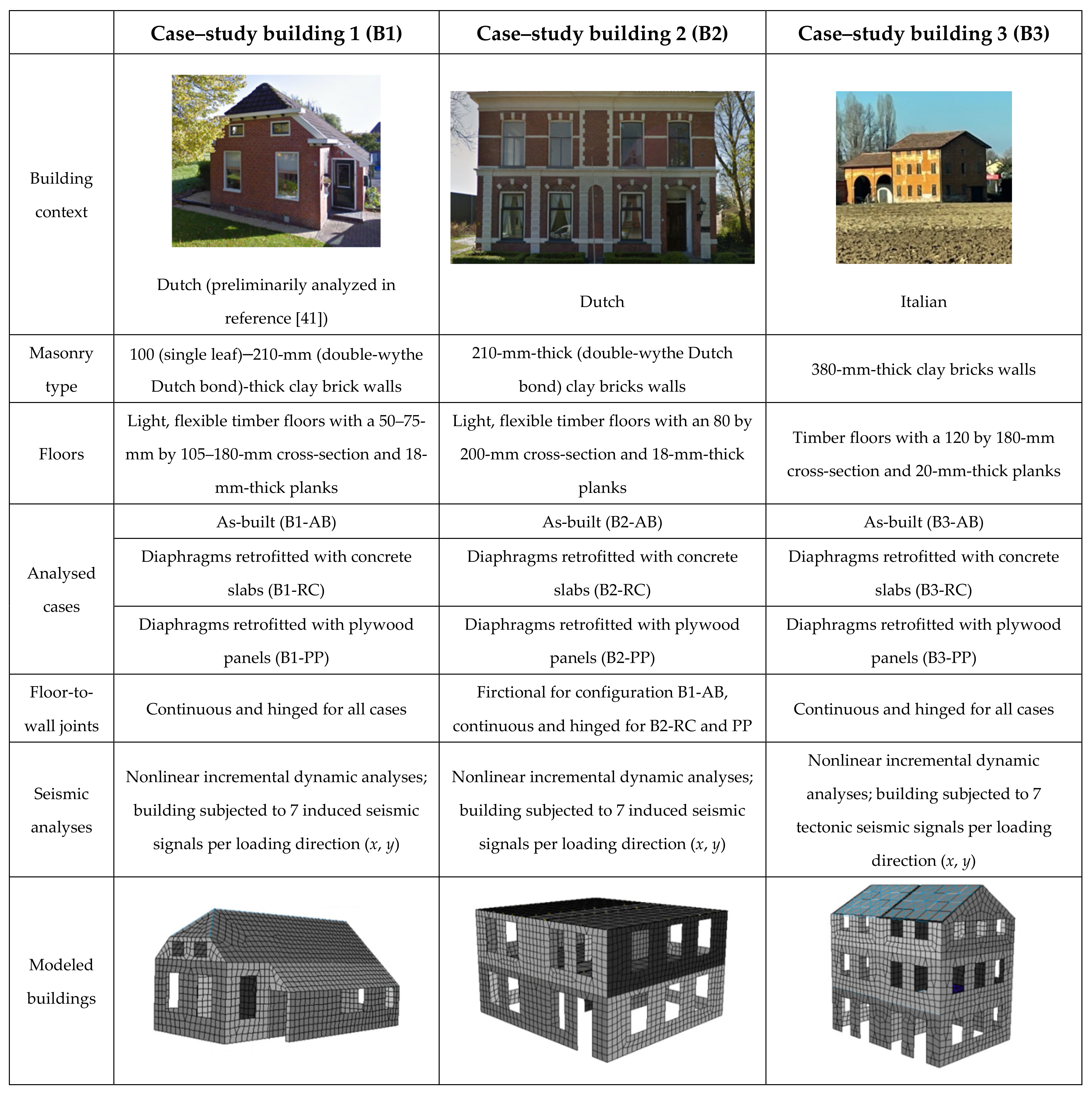
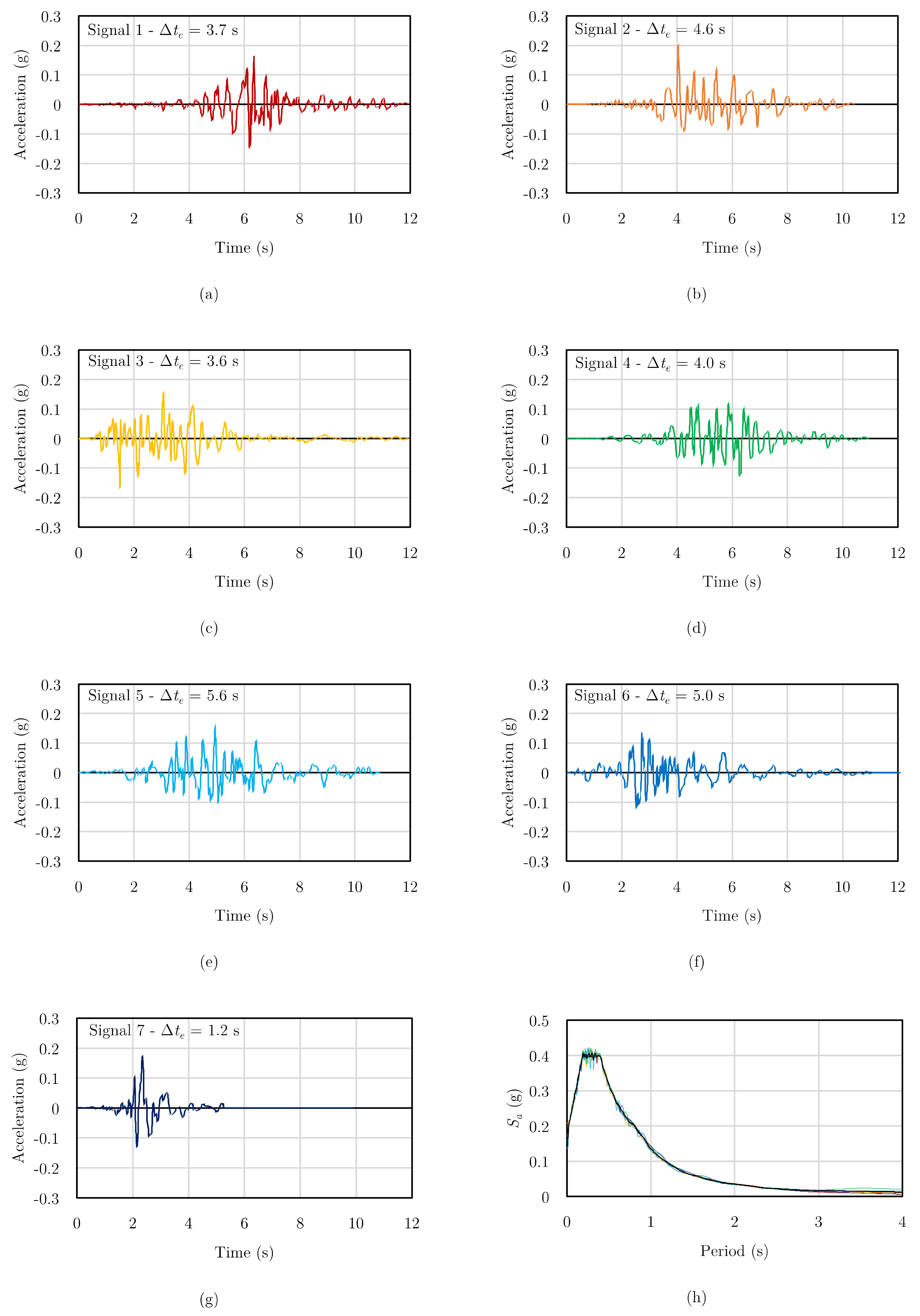
This work examines the aforementioned opportunity, starting from the specific context of the Groningen region in the northern part of the Netherlands. In that area, very frequent, human-induced earthquakes caused by gas extractions have taken place in recent years [
32]. The local building stock, composed for more than 50% of masonry buildings with timber diaphragms [
33], was not designed or realized by accounting for seismic events, since the Province of Groningen has never been a (tectonic) seismic area before. Therefore, extensive seismic characterizations have taken place since 2015 [
34] for both masonry [
35,
36] and timber [
37,
38,
39,
40,
41] structural components.
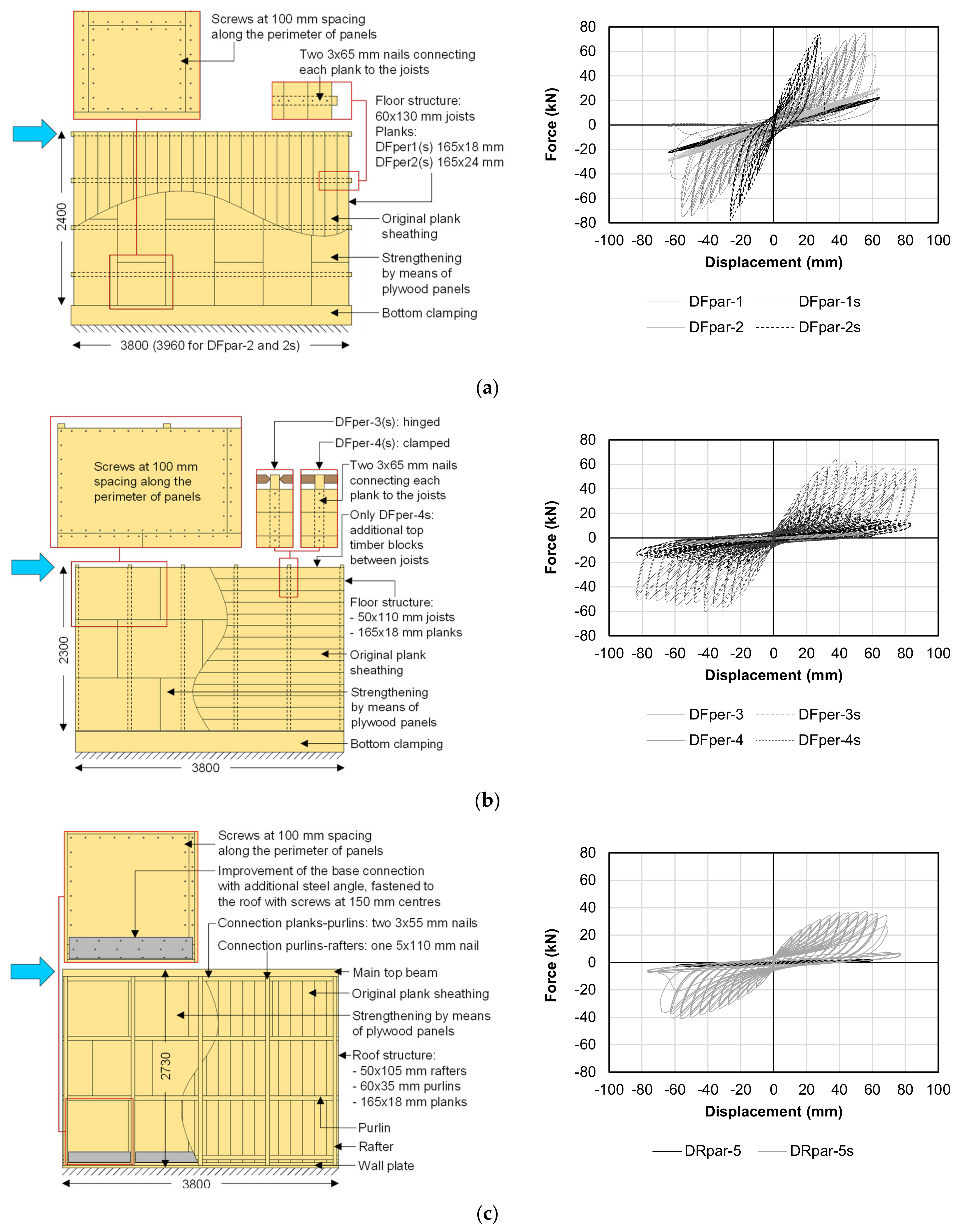
With reference to timber diaphragms, given the poor seismic performance of the as-built floors, a retrofitting method enhancing the in-plane strength, stiffness, and energy dissipation was developed [
37]. The strengthening technique consisted of an overlay of plywood panels screwed along their perimeter to the existing floor sheathing (
Figure 1). The experimental results confirmed the great potential of this retrofitting method, whose efficient design was enabled by formulating a detailed analytical model [
38]. With the developed procedure, the whole in-plane cyclic response of the strengthened floors can be predicted, including peak strength, energy dissipation, and pinching phenomena [
38]. Considering the tested floors of
Figure 1, the designed strengthening option with plywood panels is able to activate an equivalent hysteretic damping ratio of 15% [
40], a value that was also confirmed by the analytical model [
38].
This dissipative role of timber diaphragms could, therefore, be introduced in URM buildings to optimize their seismic performance. Yet, for assessing the beneficial effects of retrofitted floors, a detailed modeling of their in-plane response was necessary. Since, in numerical models, timber diaphragms are often considered as linear elastic orthotropic slabs [
42] or as rigid elements after retrofitting [
43], a macro-element modeling strategy was developed [
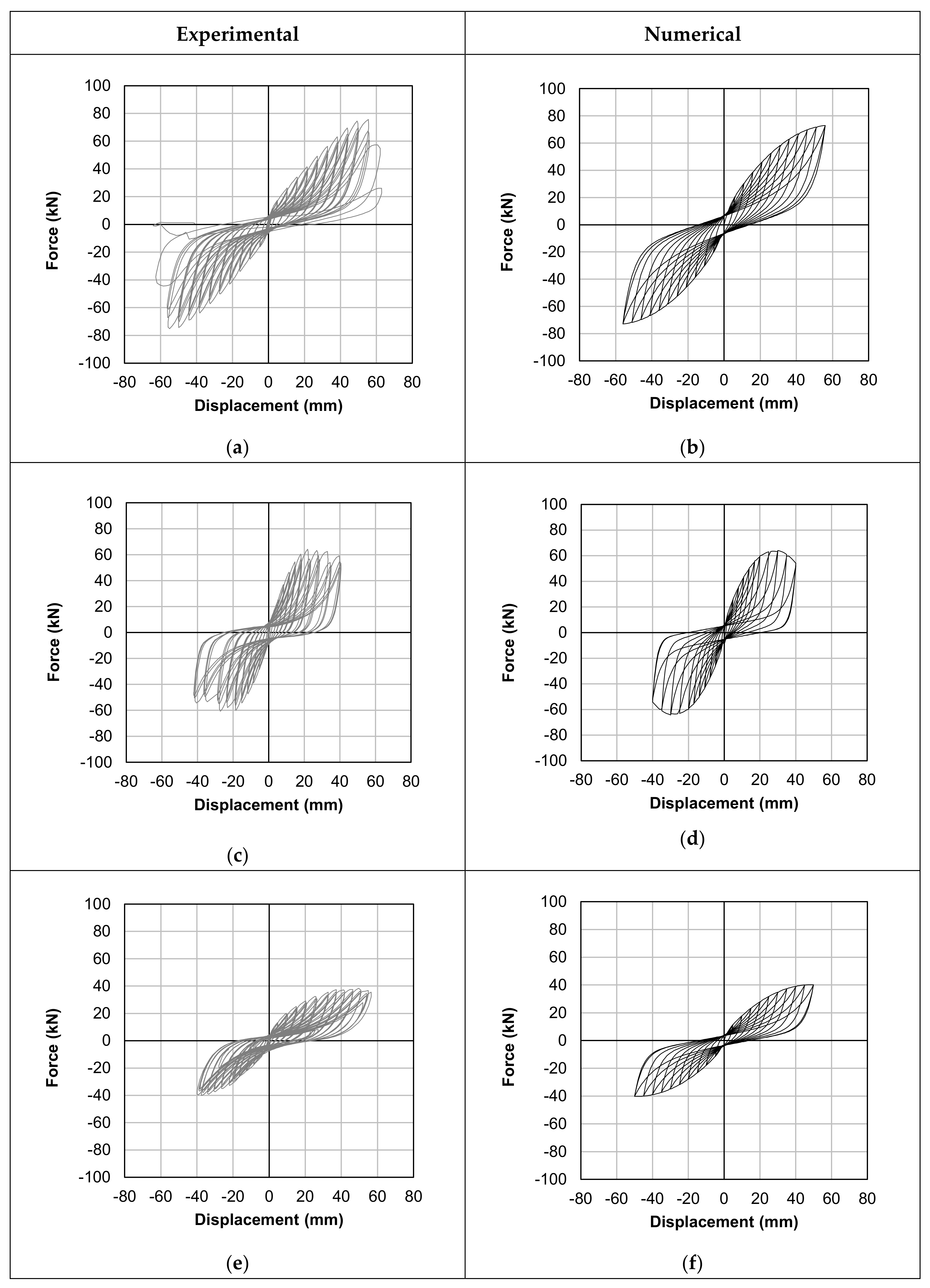
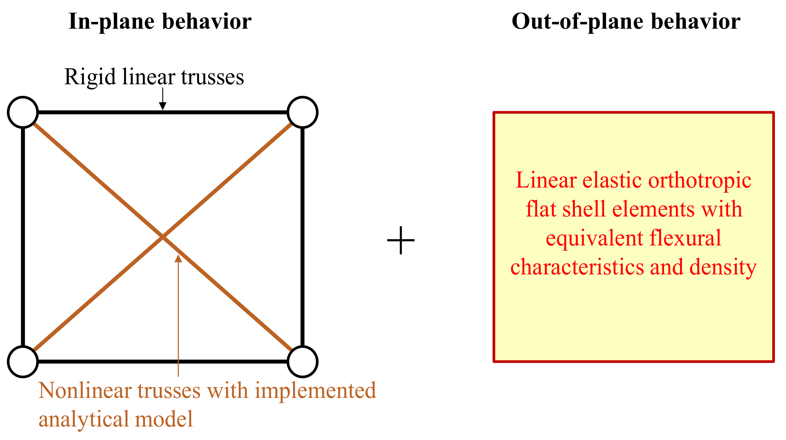
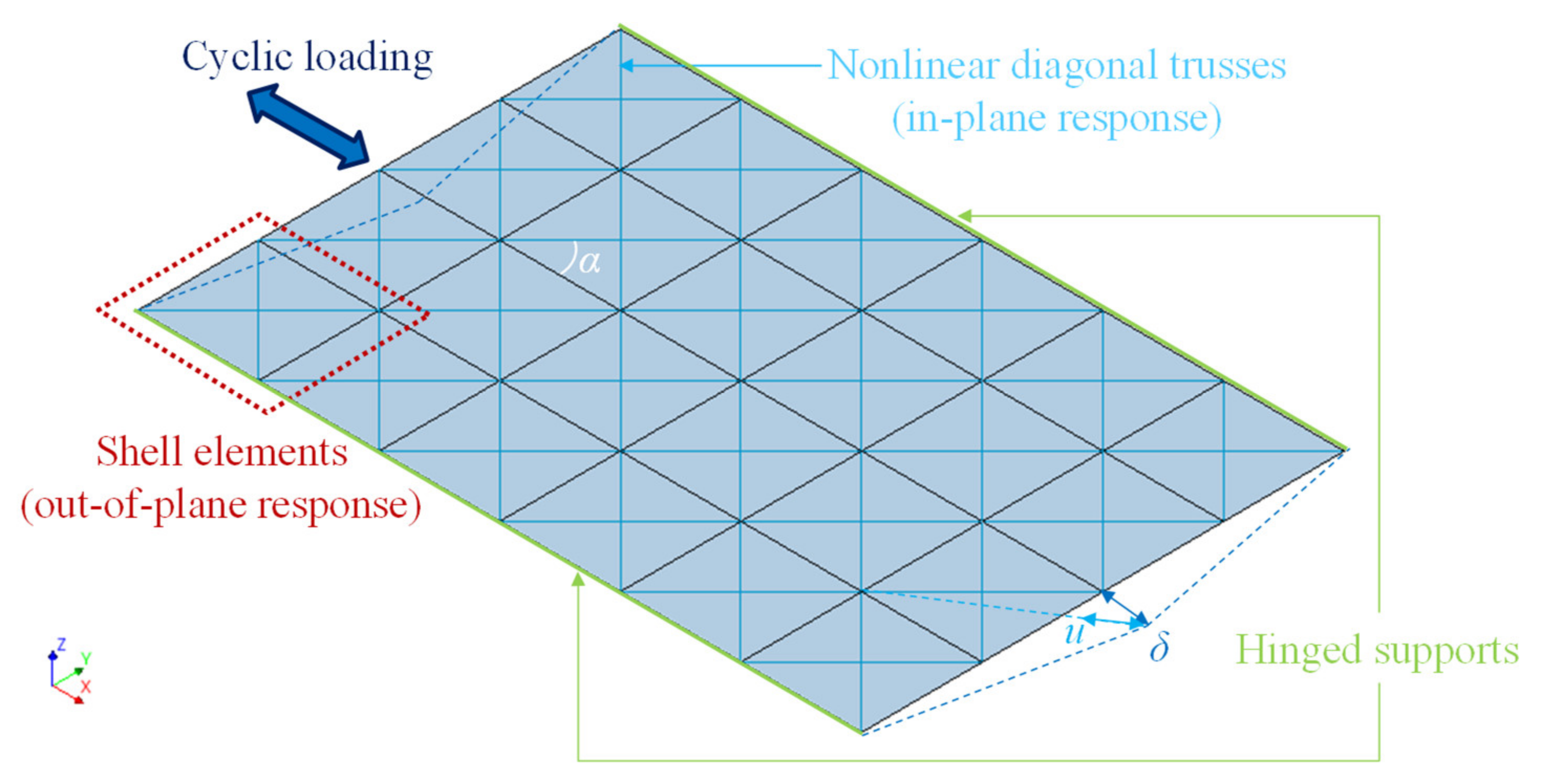
41] featuring the implementation of a user-supplied subroutine in finite element software DIANA FEA version 10.4 (DIANA FEA BV, Delft, The Netherlands) [
44] and enabling the accurate, global modeling of the nonlinear, dissipative in-plane response of the retrofitted floors [
41] (
Figure 2).
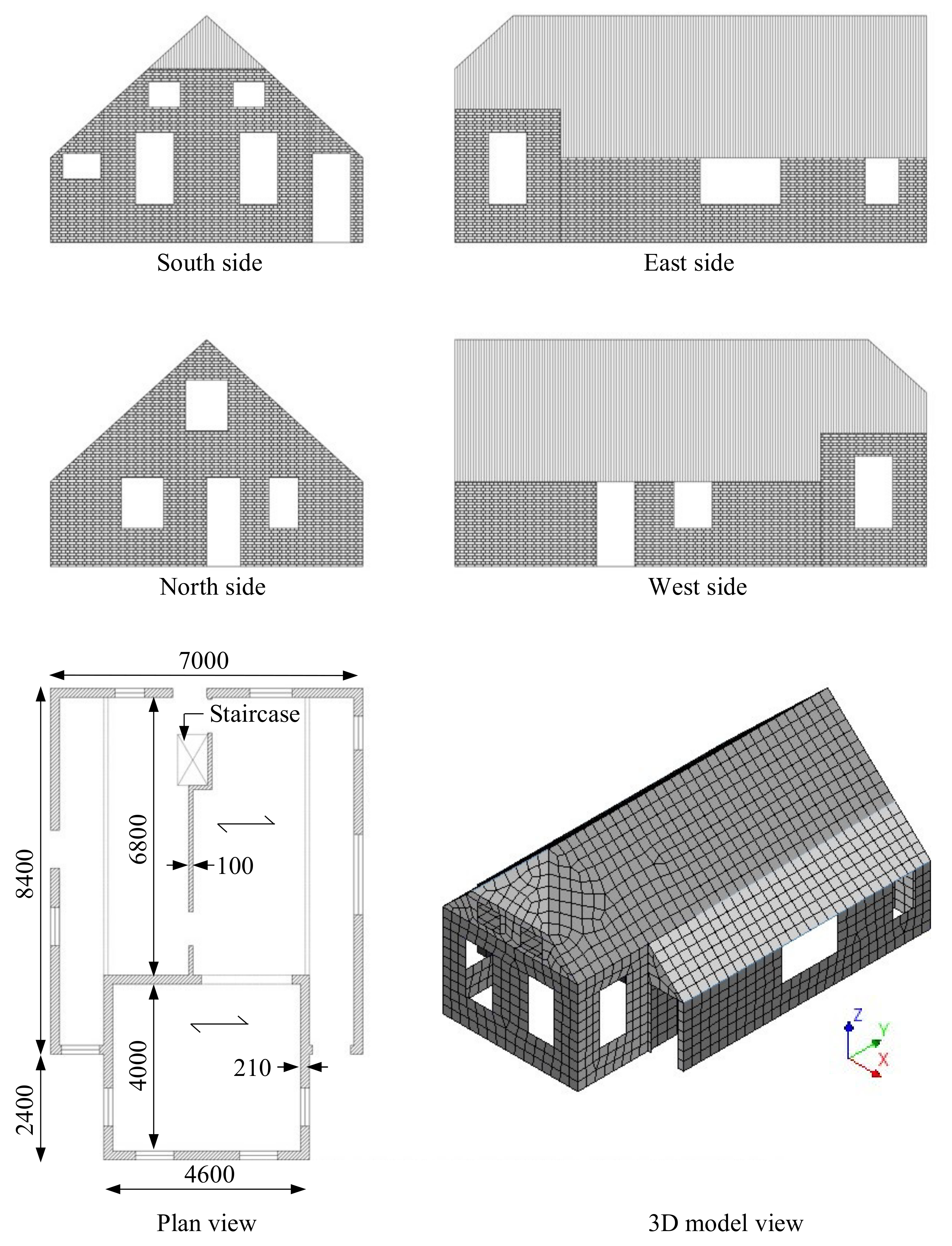
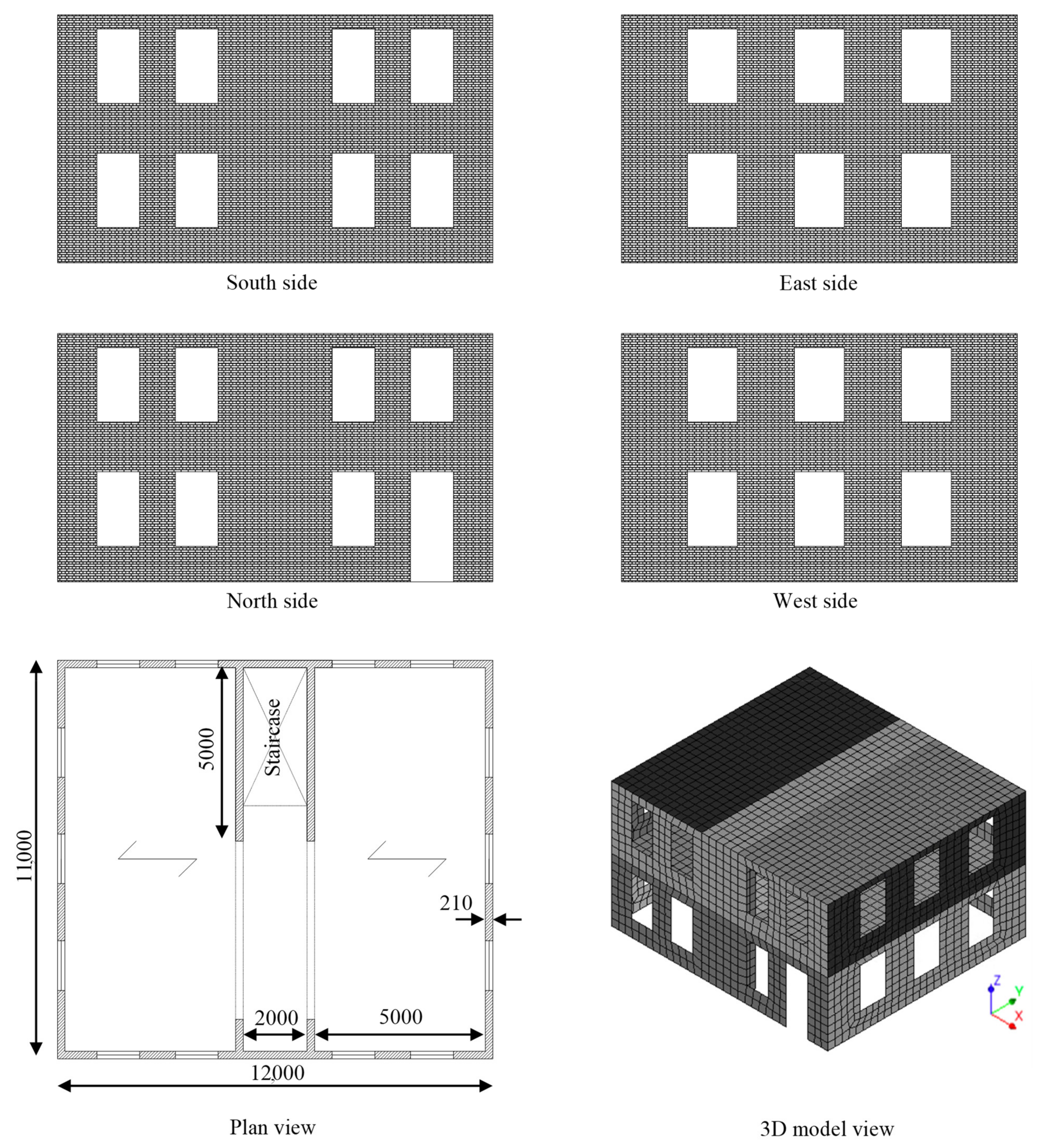
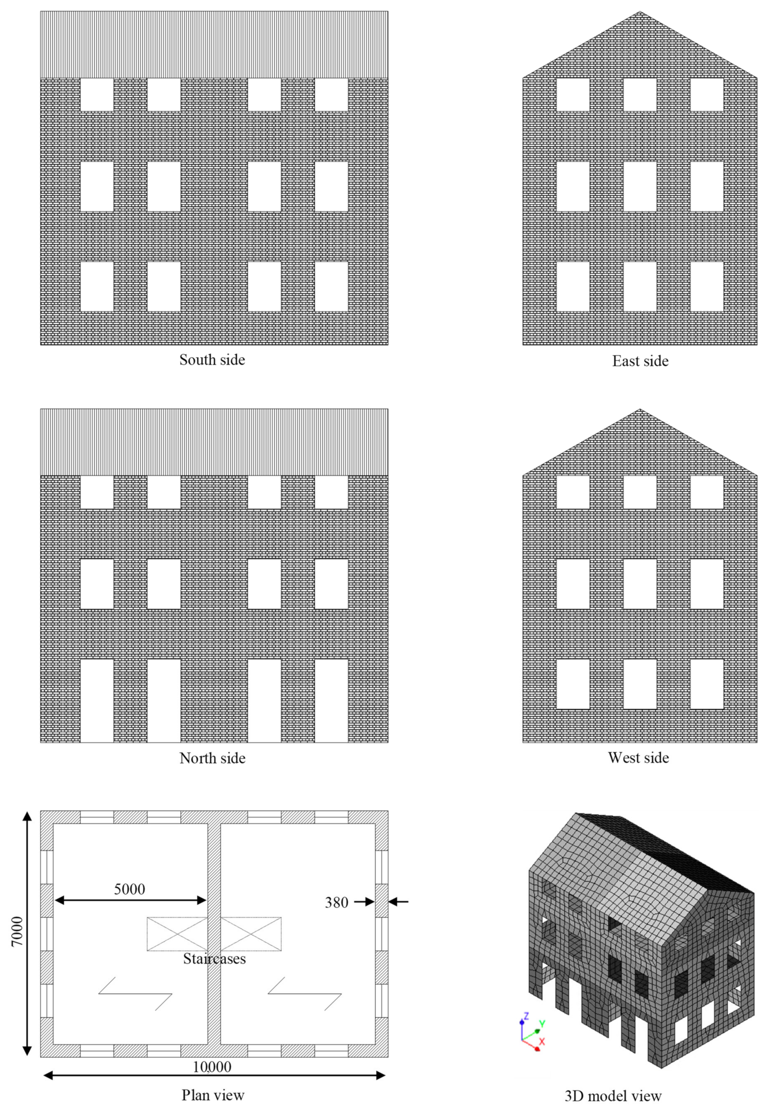
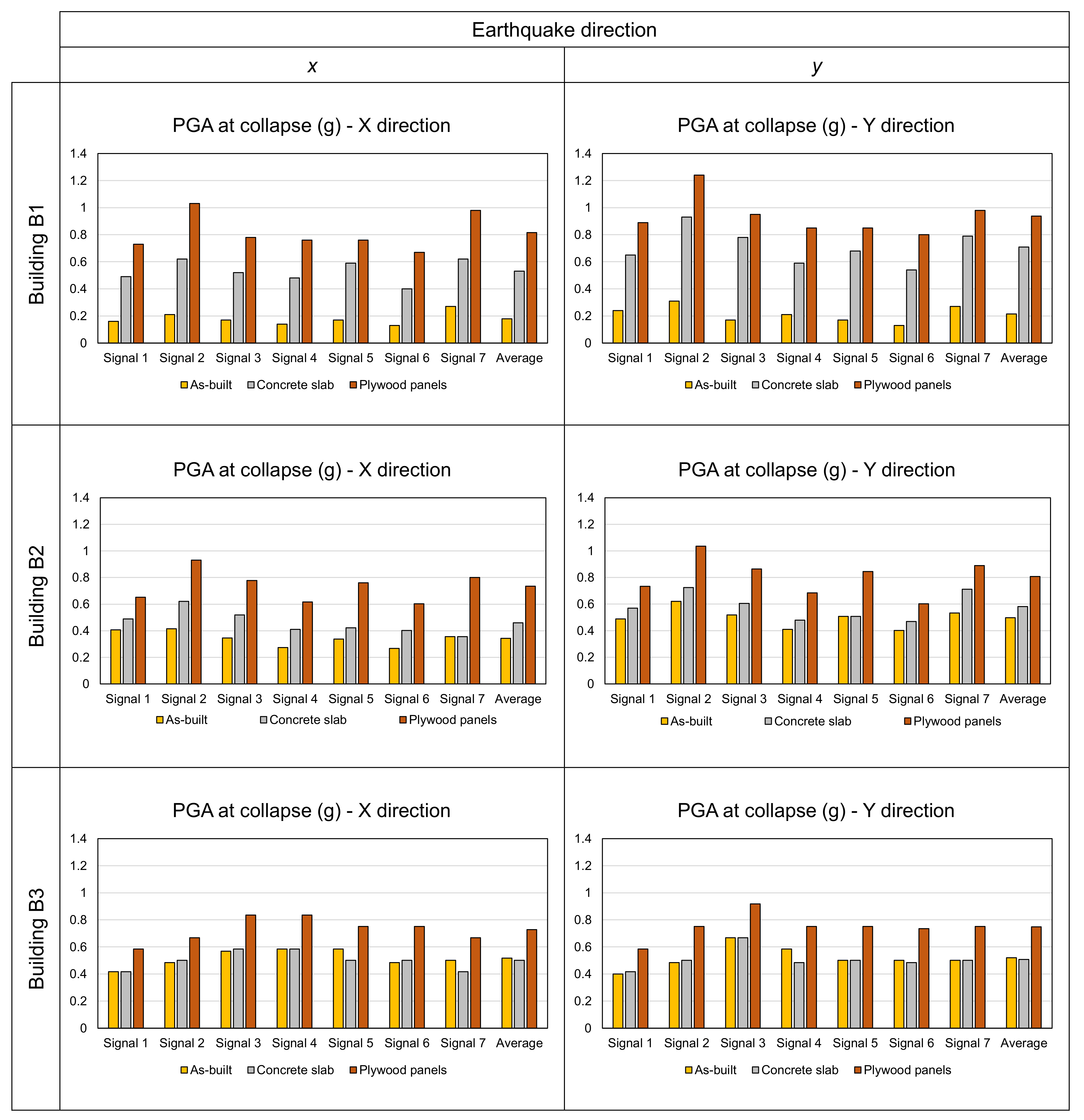
In this work, all former experimental and analytical results are combined in the analysis of three case–study URM buildings with timber diaphragms. The objective of the research study is to show how it is possible to optimize the seismic response of URM constructions with a dissipative, wood-based retrofitting technique applied to the floors in comparison to the traditional use of concrete slabs. To this end, nonlinear incremental dynamic analyses were conducted on each case–study building, considering the as-built condition, a configuration having floors strengthened with concrete slabs, and a configuration featuring plywood panel retrofitting. The performance of the buildings was quantified in terms of the peak ground acceleration (PGA) at collapse, base shear-top roof displacement curves, and hysteretic energy dissipation. In connection to this latter aspect, the impact of the strengthened diaphragms on the seismic capacity of the buildings was evaluated in terms of an equivalent damping ratio and, for the purpose of comparisons between retrofitted configurations, in terms of a behavior factor range. It should be noticed that the energy dissipation that can be activated by the diaphragms retrofitted with plywood panels depends on the design of their strengthened configurations, and namely, by the size of the panels and the number of fasteners [
38,
41]; in this case, the strengthening solutions activating the maximum energy dissipation within masonry drift limits were designed and modeled.
Figure 1.
Main characteristics and cyclic in-plane response of the timber diaphragms; floors tested parallel (
a) and perpendicular to the joists (
b) and roof pitch (
c). More details on the retrofitting technique can be found in References [
37,
38].
Figure 1.
Main characteristics and cyclic in-plane response of the timber diaphragms; floors tested parallel (
a) and perpendicular to the joists (
b) and roof pitch (
c). More details on the retrofitting technique can be found in References [
37,
38].
Figure 2.
Validation of the macro-element modeling strategy for timber diaphragms with the user-supplied subroutine based on the formulated analytical model [
38,
41]: (
a) experimental and (
b) numerical responses of a sample tested parallel to the joists; (
c) experimental and (
d) numerical responses of a sample tested perpendicular to the joists; (
e) experimental and (
f) numerical responses of a sample representing a roof pitch.
Section 2 provides an overview of the examined configurations of the case–study buildings, as well as the methodology followed for analyzing their seismic response and quantifying the dissipative role of the timber diaphragms. In
Section 3, the results of the time–history analyses are reported in detail, and the performance of the case–study buildings is examined. Subsequently,
Section 4 discusses these outcomes, with a specific focus on the role of the (retrofitted) floors. Finally, the conclusions of this study are reported in
Section 5.
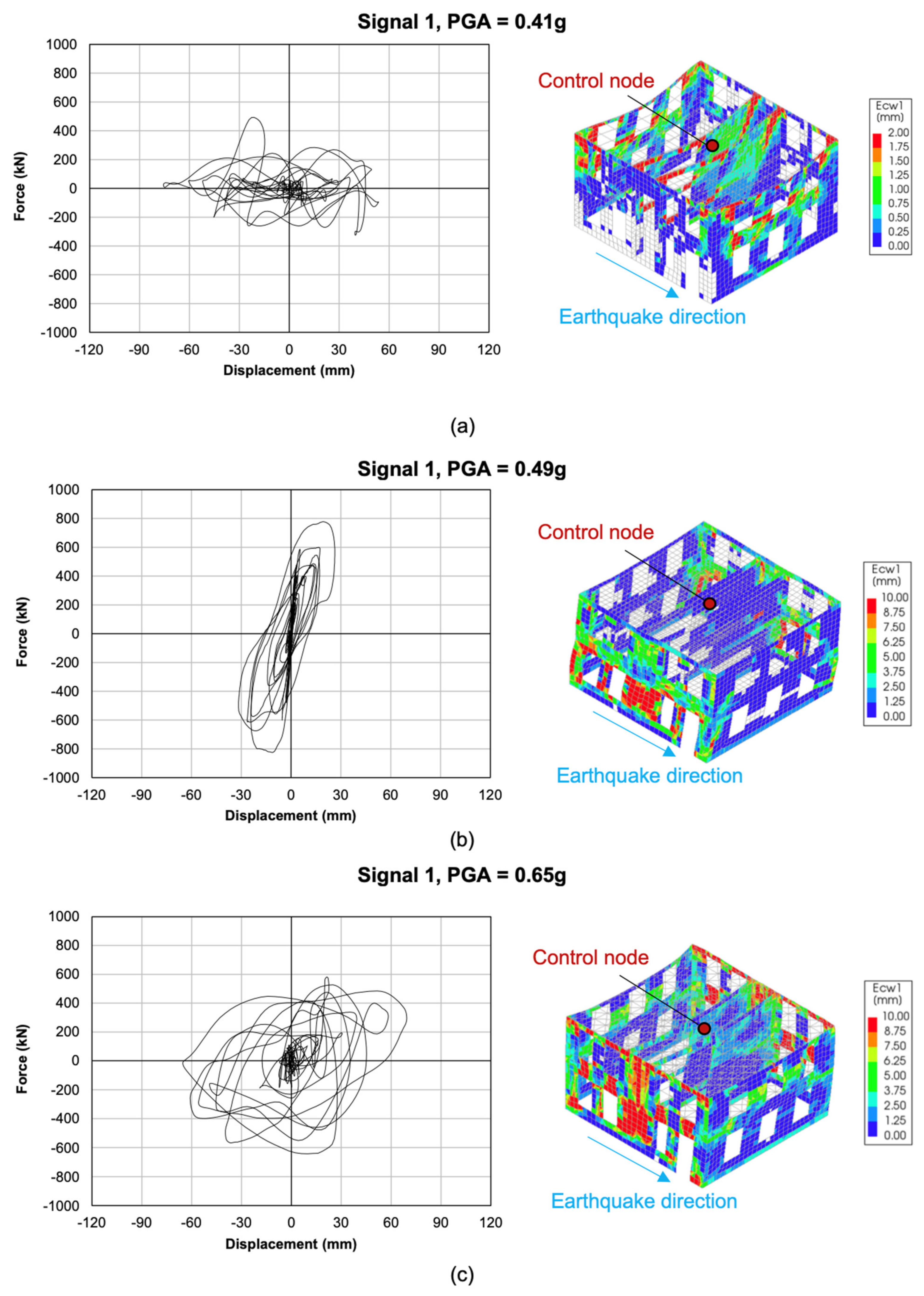
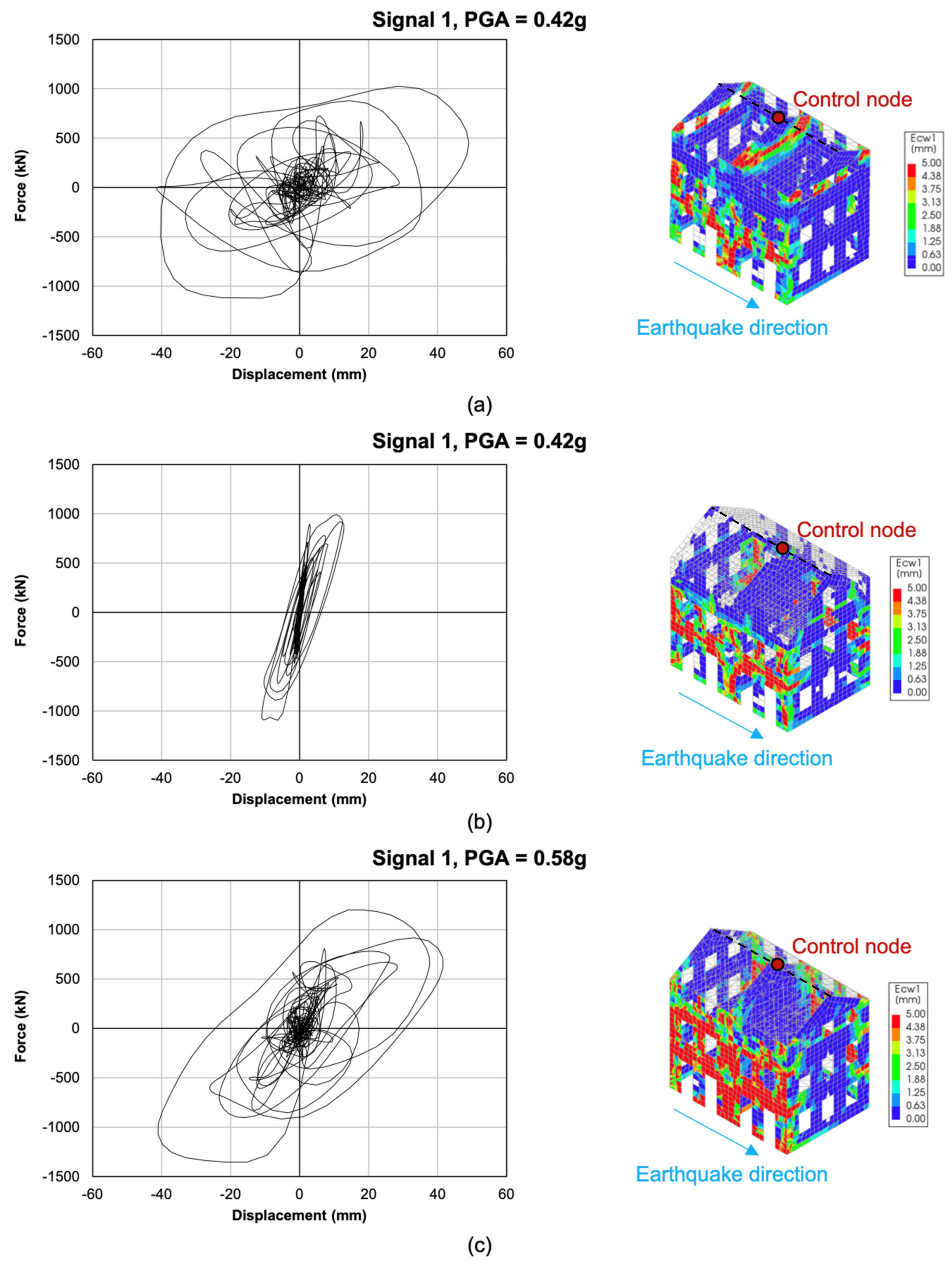
4. Discussion
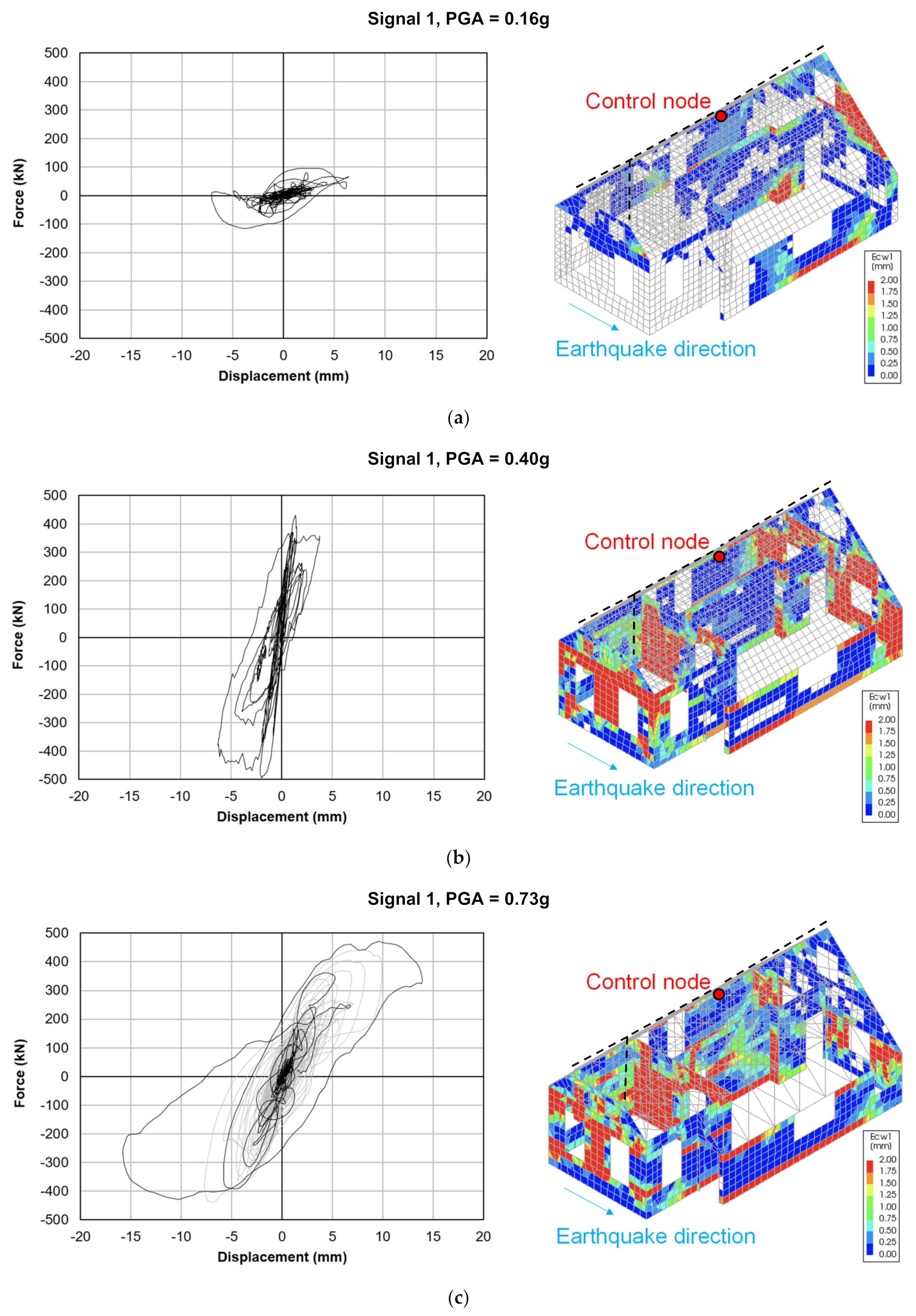
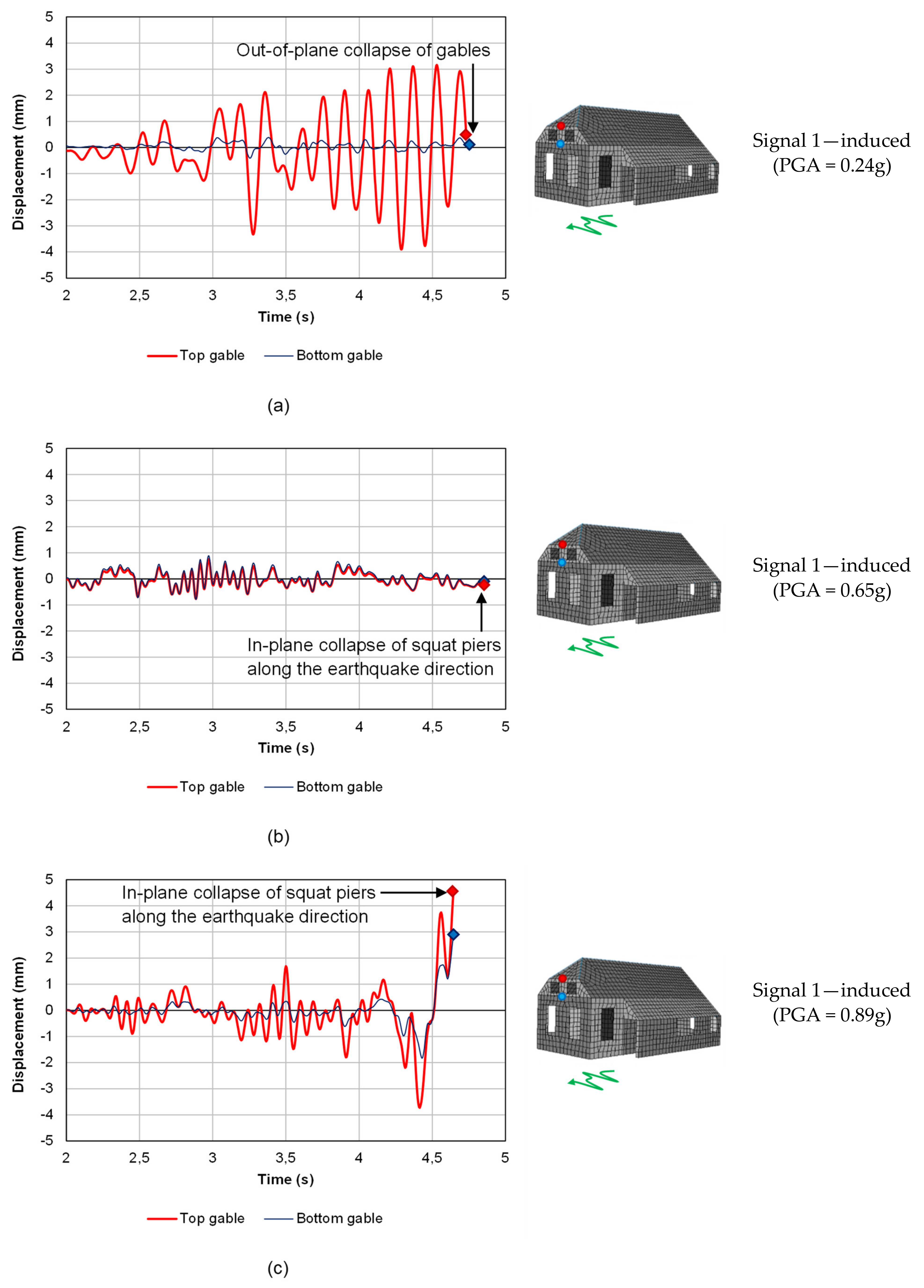
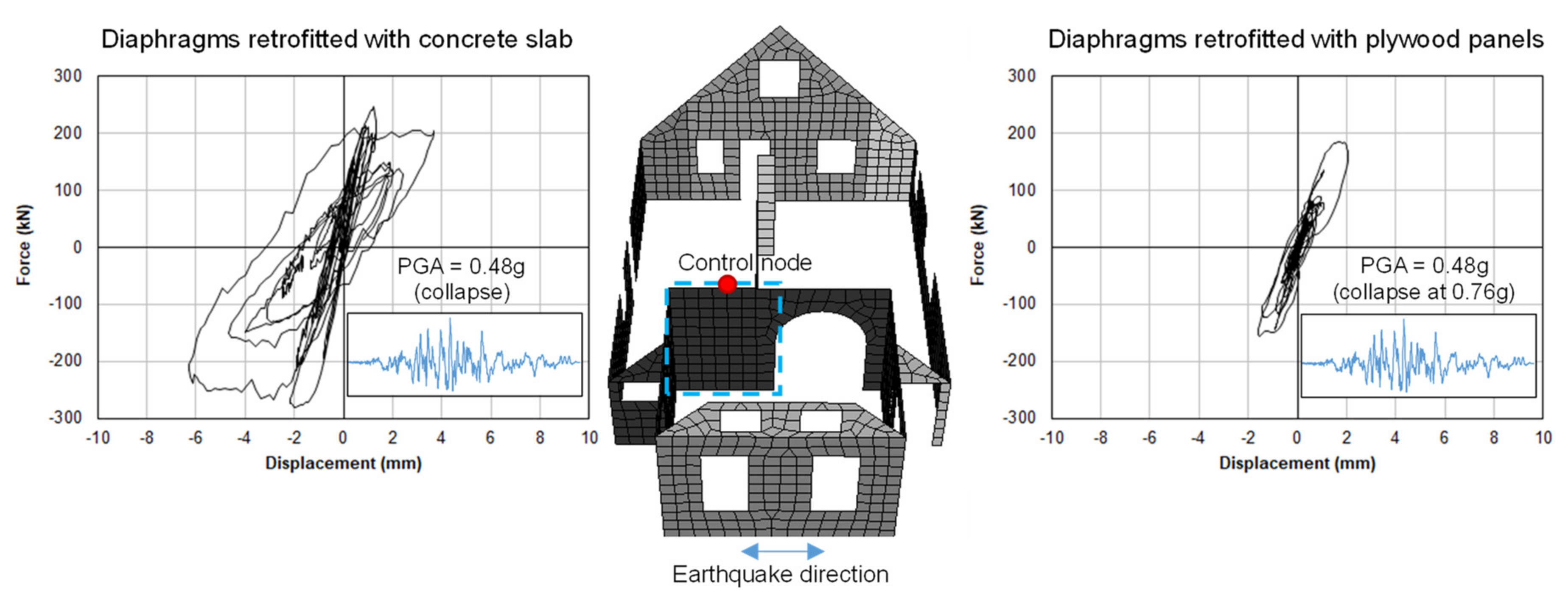
The results of the three analyzed case–study buildings highlighted once more how the role of timber diaphragms in the seismic response of URM buildings can be crucial. The effect of the in-plane stiffness of the floors is firstly discussed, taking into account additional control nodes with respect to those selected in
Figure 12,
Figure 13 and
Figure 14. Considering the out-of-plane seismic response of the front gable in building B1 (
Figure 18), this can be regarded as one of its most vulnerable portions due to its reduced thickness (only 100 mm). The insufficient in-plane stiffness of the existing roof (
Figure 18a) leads to a premature out-of-plane collapse of the gable, highlighted by the large, out-of-phase relative displacement between the two control nodes. This local collapse, if compared to the cases featuring stiffened diaphragms, occurs for a relatively low seismic acceleration, justifying the need of a retrofitting intervention. When the concrete slab retrofitting is applied (
Figure 18b), the two control nodes display an identical displacement time–history, as expected with a rigid diaphragm system. The collapse of the building is, in this case, not related to the gable, as in the as-built situation, but to the in-plane failure of the squat walls along the earthquake direction. This same failure type was observed for configuration B3-PP (
Figure 18c), which displayed a hybrid response: the floors retrofitted with plywood panels proved to be sufficiently stiff to activate the in-plane failure of the walls but also allowed for a limited out-of-plane displacement in the gable, activating energy dissipation in the strengthened roof.
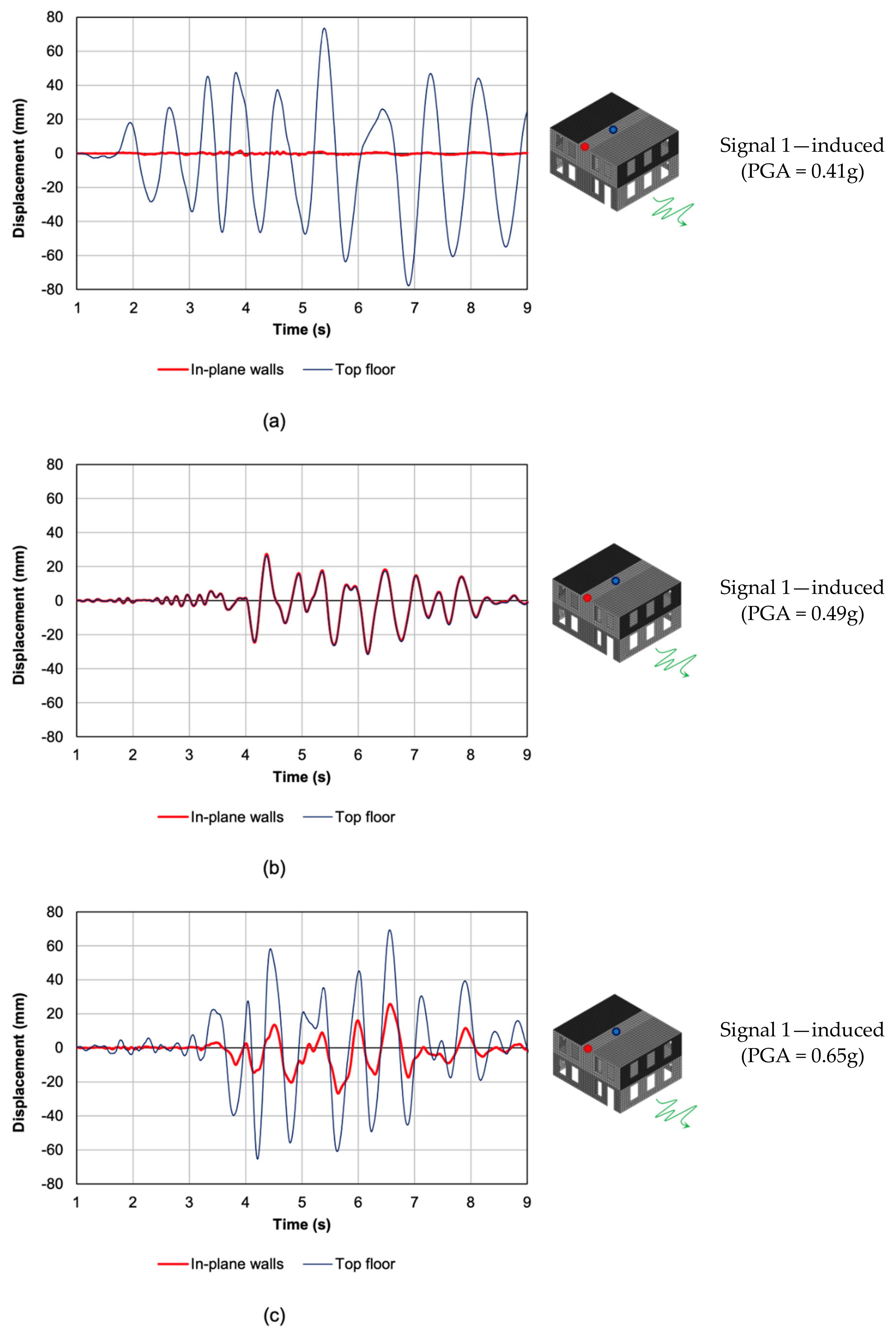
The performed analyses also showed that the in-plane stiffness of the floors is responsible for how quickly the masonry piers are brought into play; this is exemplified in
Figure 19 for building B2, taking into account the displacements of a control node on the roof and of one on the lateral walls. When considering the existing floors (
Figure 19a), on the one hand, their low stiffness and deflection capacities could positively prevent the in-plane walls from being excessively solicited; on the other hand, their flexibility led to out-of-plane collapses and to an independent movement of each floor without retrieving the desired box behavior. With rigid concrete diaphragms (
Figure 19b), the deflection of the floors is absent, and the diaphragms and walls undergo the same displacement. This solution guarantees the maximum redistribution of seismic shear forces and an excellent box behavior but directly brings the walls’ strength into play. When an optimized, dissipative retrofitting is chosen (
Figure 19c), it is possible to link the displacement capacity of the diaphragms, enabling their energy dissipation potential, with an in-plane stiffness sufficient to redistribute seismic loads among the walls. Thus, similar to building B1-PP, the in-plane capacity of the piers is retrieved, but the damping effect of the floors can prevent this from occurring right at the beginning of the seismic signal, with an increase of the seismic capacity of the building.
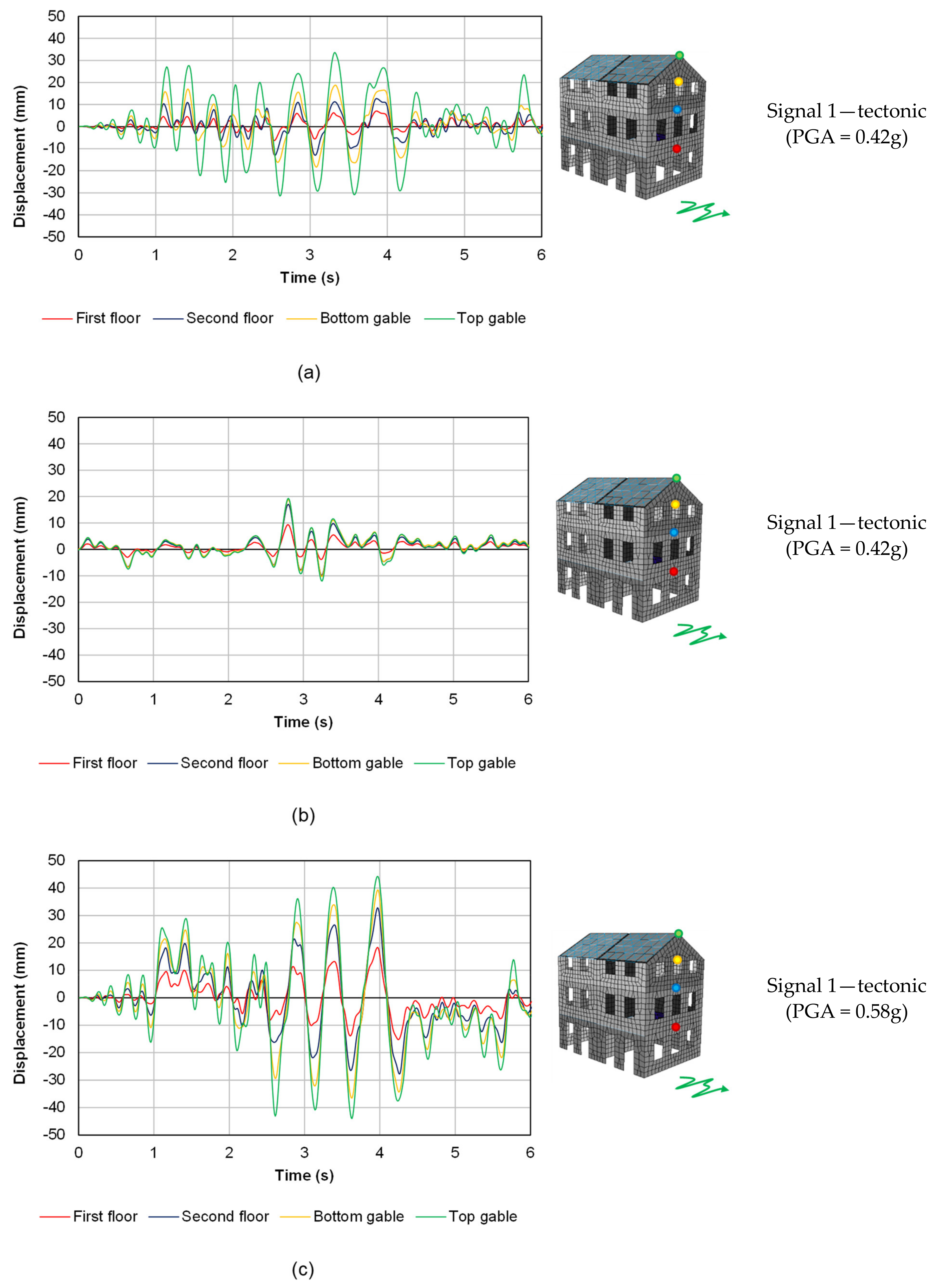
The previously discussed results were again obtained in case–study B3 (
Figure 20), subjected to tectonic earthquakes. Considering the control nodes at each floor level and at the top and bottom of the gable, configuration B3-AB (
Figure 20a) showed that the existing flexible floors are sufficient to retrieve the in-plane strength of the walls because of the massive structure of the piers. However, the as-built floors cause extensive damage to the gables, where the largest relative displacements are recorded, and a dangerous out-of-phase movement of each floor level. In configuration B3-RC (
Figure 20b), the observed displacements are all linked to the in-plane capacity of the walls because of the presence of rigid diaphragms. The response also shows an improved box behavior, but the PGA at collapse is interestingly the same as configuration B3-AB, as pointed out and discussed in
Section 3.1. Finally, configuration B3-PP (
Figure 20c) shows a combination of the two previous cases; as can be noticed, the presence of optimally designed retrofitted diaphragms induces an in-phase movement of the floor levels while reducing the dangerous relative displacement between the top and bottom of the gable and retrieves, at the same time, the in-plane capacity of the piers. This combination maximizes once more the hysteretic energy that can be activated and dissipated by the building, with a beneficial effect in its seismic response.
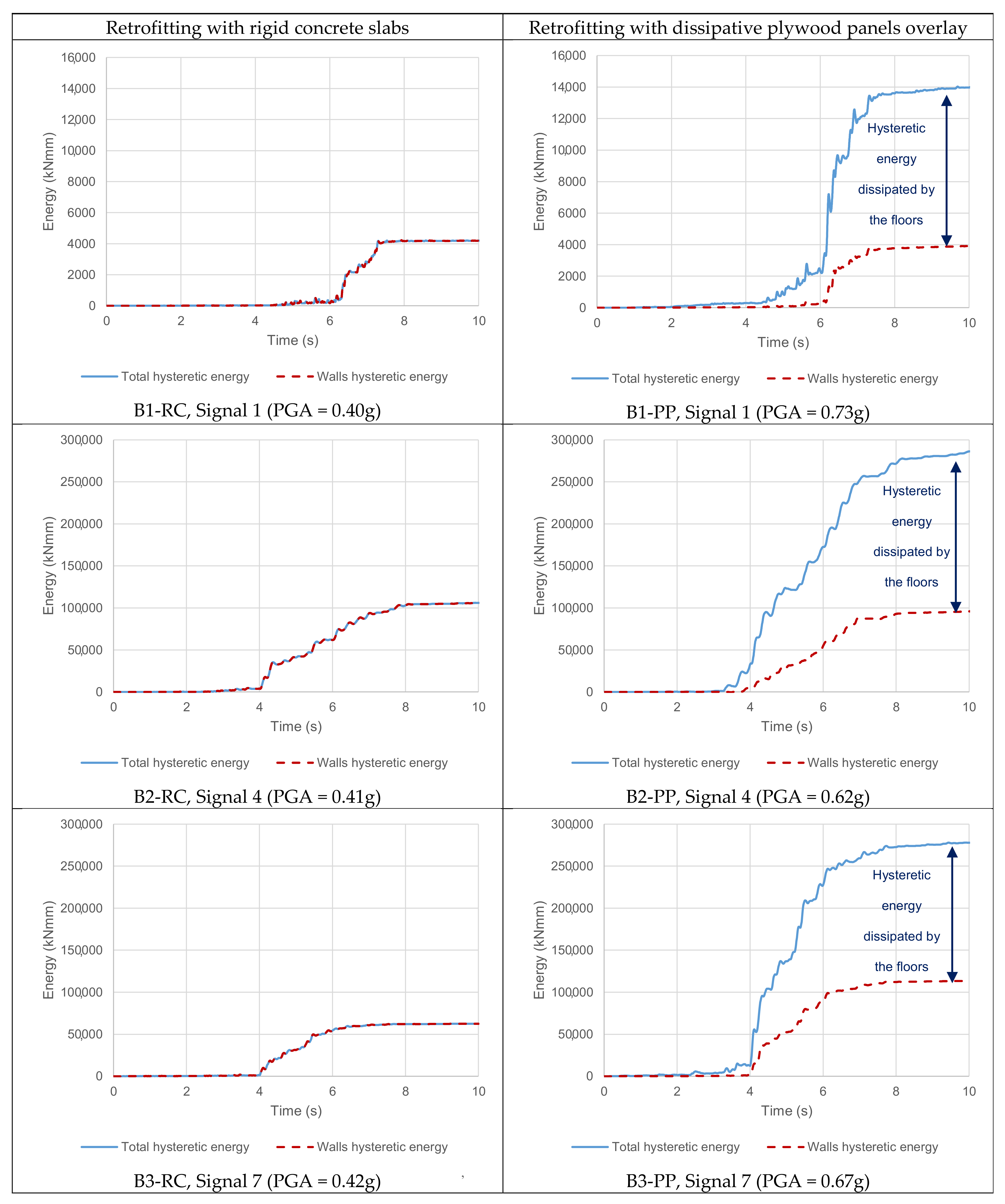
The damping effect induced by the plywood panels retrofitting is also evident in
Figure 21, comparing the response of the most solicited wall in building B1 when the diaphragms are retrofitted with concrete slabs or plywood panels; as can be noticed, under the same signal, when concrete slabs are present, the pier reaches its capacity after a shear diagonal failure; with plywood panels retrofitting, a damping effect on the wall is noticeable, and the maximum in-plane load for the pier is reached by further amplifying the signal to more than 35% compared to that applied to the B1-RC configuration. Yet, it is important to underline that, in order to be able to activate the dissipative potential of the floors, a dry screed made of loose materials (so that the diaphragms are not further stiffened by this component), as well as a continuous and resistant connection between the diaphragms and walls, has to be realized so that local collapses can be prevented and the box behavior can still be enabled [
41].
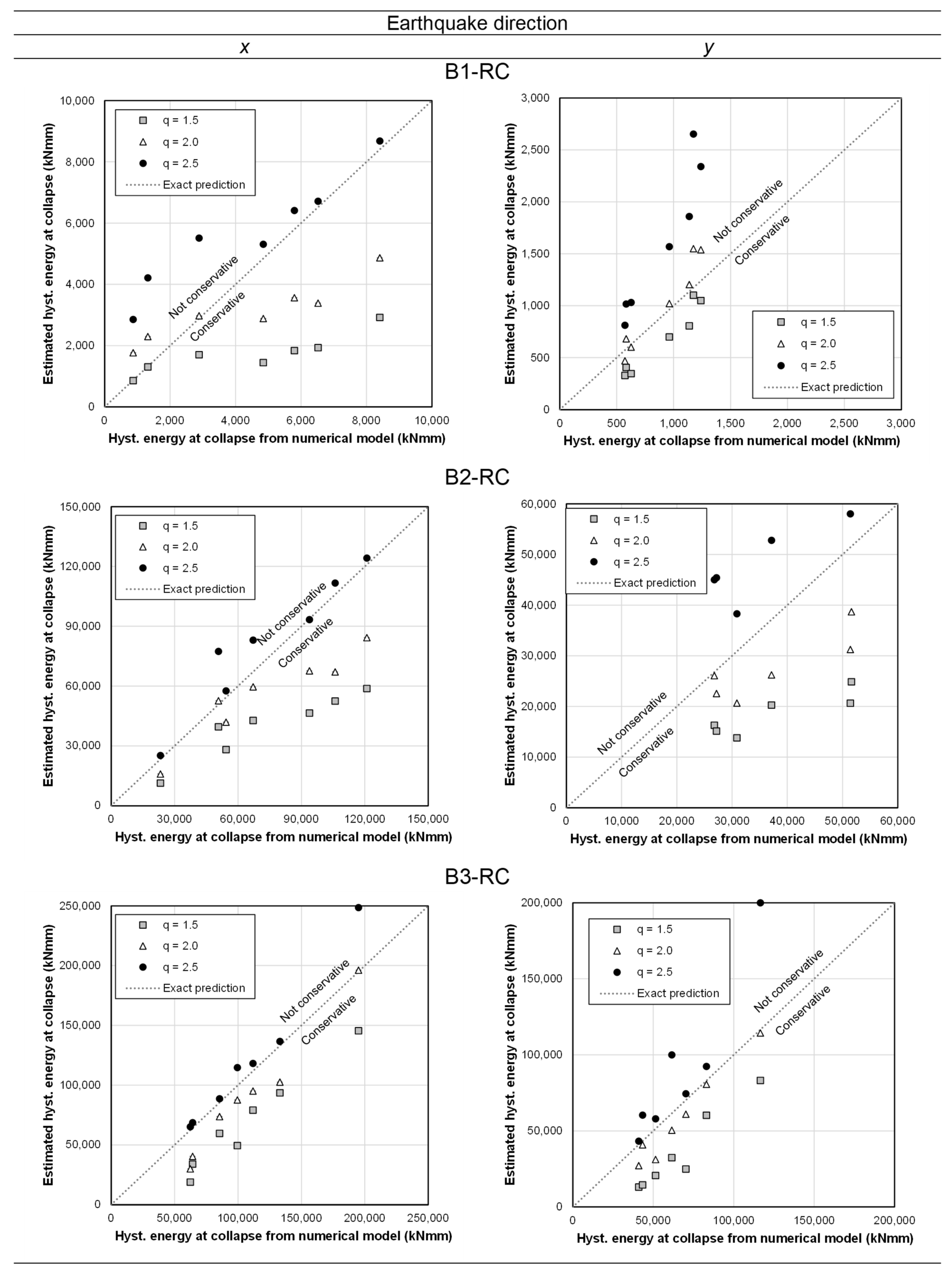
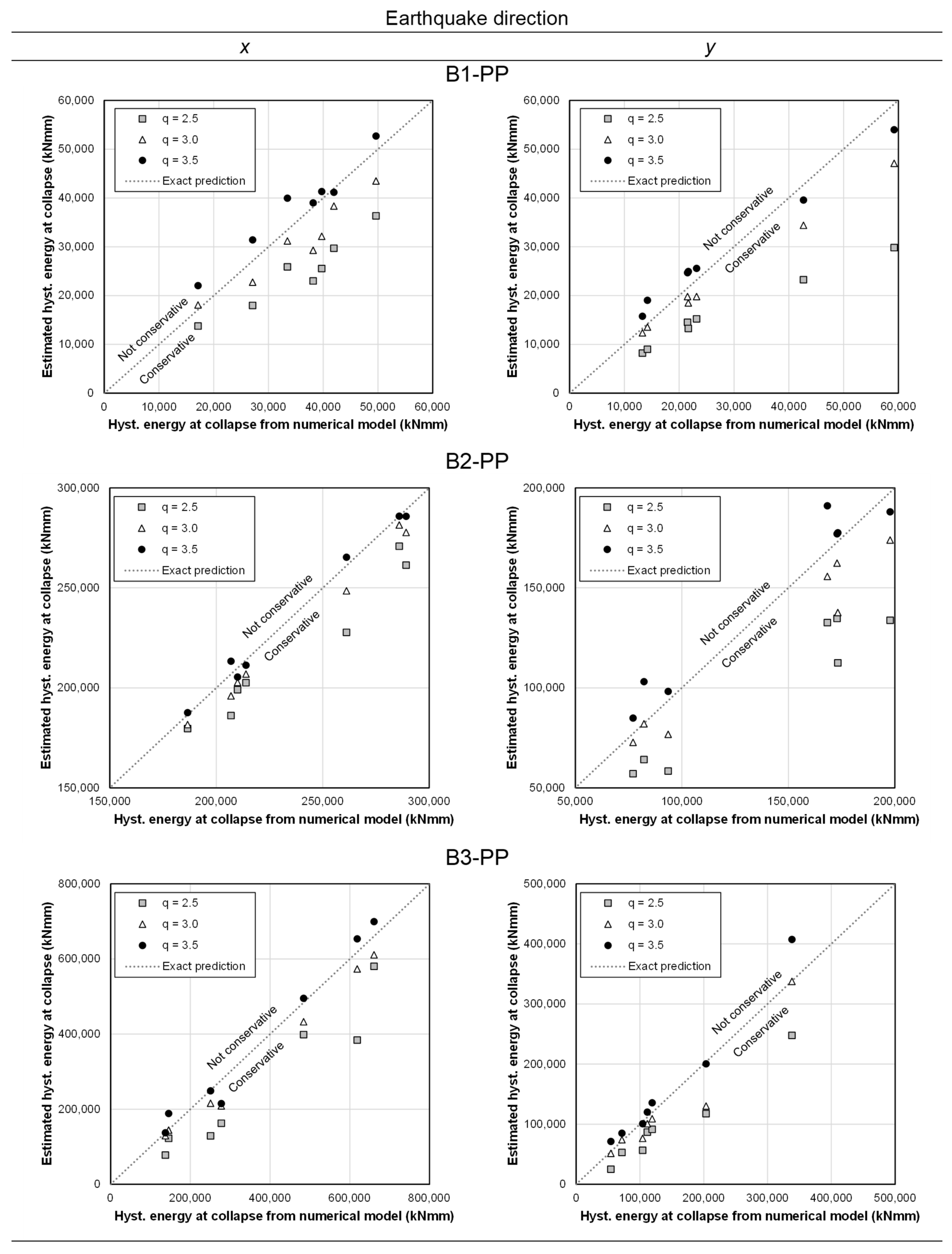
With reference to the increase in seismic capacity, in Reference [
40], a value of equivalent hysteretic damping ratio
ξ = 15% was determined for the diaphragms retrofitted with plywood panels. From the performed analyses, it appears that the difference in PGA at collapse between the configurations with stiff floors and those having dissipative diaphragms was, on average, approximately 30% (see
Figure 11). This result thus confirms the obtained 15% equivalent damping ratio value; if the floors were retrofitted with plywood panels, and for a simplified modeling (e.g., a pushover analysis), they were assumed as stiff; their dissipative contribution could be taken into account by considering an overdamped spectrum reduced by the factor
η = [10/(5 +
ξ)]
1/2 [
54]. It is interesting to notice that
η = 0.707 for
ξ = 15%, a value suggesting that, when a dissipative retrofitting of the floors is designed, the demand response spectrum could indeed be reduced by approximately 30% in addition to the further nonlinear contributions of the in-plane masonry walls.
Furthermore, the largely increased hysteretic energy that can be activated in the URM buildings because of the presence of retrofitted, dissipative timber diaphragms was also linked to a higher behavior factor range of
q = 2.5–3.5. It should be noticed that these values could be obtained considering very regular, low-rise buildings with homogeneous and well-connected masonry—thus, in almost ideal conditions when dealing with the seismic assessment and retrofitting of existing buildings; this was also confirmed by the large values of PGA obtained at collapse. Nevertheless, these same conditions of regularity and homogeneity of the masonry were applied for the configurations with concrete slabs. Therefore, by adopting the obtained behavior factor ranges as indicators for comparison, the increase in energy dissipation activated by the plywood panels retrofitting was tangible and could be predicted and validated. As a recommendation for further studies, since past shake table tests [
61] highlighted that the use of the lower limit value of
q = 1.5 should be preferred for buildings with rigid diaphragms, similar (full-scale) experiments could be performed to assess the potential increase in the behavior factor provided by an optimized, dissipative, wood-based strengthening of the timber floors in URM buildings.
5. Summary and Conclusions
In this work, the possibility of optimizing the seismic performance of URM buildings through the retrofitting of timber diaphragms was investigated, transforming them into dissipative structural components. Numerical time–history analyses were conducted on three case–study buildings, considering the as-built state with flexible floors, a retrofitting option with concrete slabs (and, thus, rigid floors), and a dissipative strengthening method consisting of plywood panels screwed on the existing diaphragms.
It was shown that, in order to optimize the seismic response of URM buildings, the retrofitting of timber diaphragms can be designed based on the pertaining floor seismic shear and masonry out-of-plane drift limits. In this way, the diaphragms can undergo the maximum deflection without causing out-of-plane collapse, activating at the same time the maximum base shear of the building: thus, the maximum energy dissipation can also be retrieved from the diaphragms. Yet, in order for the floors to efficiently transfer the seismic shear loads and deflect without causing local masonry collapses, the timber–masonry joints have to be effectively strengthened accordingly, as their role is paramount to efficiently redistribute the actions on the URM structure. Instead, if the diaphragms are too flexible, severe out-of-plane damage or collapses are observed, while, with rigid floors, the box behavior of the building is improved, but the dissipative contribution of the diaphragms cannot be activated.
The relevant, dissipative effect of well-retrofitted, optimized timber floors was quantified in terms of an equivalent hysteretic damping ratio of 15% additional to the dissipation already provided by the masonry walls. Besides, in the presence of optimally designed dissipative diaphragms, an increased behavior factor range of q = 2.5–3.5 was observed in comparison to the range of q = 1.5–2.5 for rigid floors. Throughout the analysis, this parameter was used to quantify the energy dissipation for the purpose of comparisons among the retrofitted configurations and refers to regular buildings featuring homogenous and well-connected clay brick masonry, as well as continuous floor-to-wall connections. Thus, it is expected that these values reflect almost ideal conditions when dealing with the seismic assessment and retrofitting of existing buildings; however, the obtained values still prove the beneficial effect of an optimized strengthening of timber diaphragms with respect to rigid floors. Hence, further (experimental) studies for validating the dissipative role of wood-based retrofitting techniques for timber floors in URM constructions are highly encouraged and recommended, so that a possible increase in the behavior factor can be assessed for real building prototypes as well.
The obtained results can further support a more aware seismic retrofitting of existing URM constructions, with specific references to the use of wood-based (dissipative) strengthening techniques as a more beneficial alternative to rigid concrete diaphragms, and can contribute to the research framework supporting the conservation of the architectural heritage of seismic-prone countries.


